Embed Size (px)
Citation preview
Surface & Coatings Technology 203 (2008) 730–735
Contents lists available at ScienceDirect
Surface & Coatings Technology
j ourna l homepage: www.e lsev ie r.com/ locate /sur fcoat
Cohesive zone effects on coating failure evaluations of diamond-coated tools
J. Hu a, Y.K. Chou a,⁎, R.G. Thompson b
a Mechanical Engineering Department, The University of Alabama, Tuscaloosa, Alabama, United Statesb Vista Engineering, Inc., Birmingham, Alabama, United States
⁎ Corresponding author.E-mail address: [email protected] (Y.K. Chou).
0257-8972/$ – see front matter © 2008 Elsevier B.V. Aldoi:10.1016/j.surfcoat.2008.08.029
a b s t r a c t
a r t i c l e i n f oAvailable online 20 August 2008
Diamond-coated cutting tooKeywords:Coating failureDiamond coatingFinite elementInterface delamination
ls are economically attractive alternatives to polycrystalline diamond tools formachining applications. Despite the superior tribological and mechanical properties, the advantages ofdiamond-coated tools, however, have been largely compromised by the insufficient coating–substrateadhesion. Interface characteristics are important in the failure and performance of diamond-coated tools. Inthis study, a cohesive zone model was incorporated to investigate diamond-coating tungsten carbide (WC)systems. The cohesive zone model is based on the traction–separation law, represented by four parameters:the maximum normal and shear strength and the normal and shear characteristic lengths, whose valueswere determined from WC fracture properties. The cohesive zone model was implemented in finite elementcodes to simulate indentation on a coating–substrate system.The model was applied to examine the interface behavior during the indentation, the role of the cohesivezone in the failure mechanism of coating systems, and the coating Young's modulus and thickness effects ondifferent failure modes. The simulation results are summarized as follows. (1) The cohesive zone interfacedoes not affect the critical load for coating surface tensile cracking, but affects the plastic strain duringloading. (2) If the coating Young's modulus increases, the coating surface cracking will decrease, however, theinterface delamination resistance will increase. (3) Increasing the coating thickness will generally increasethe critical load for surface cracking, but will have an opposite effect when the coating exceeds a certainthickness. Moreover, thicker coatings typically reduce the interface delamination.
© 2008 Elsevier B.V. All rights reserved.
1. Introduction
Diamond coatings using advanced surface engineering technolo-gies have been increasingly explored for tooling applications inmachining. Diamond-coated tools are economically attractive alter-natives to their polycrystalline diamond counterparts, offering anadvantage in the fabrications of cutting tools with complex geometrysuch as drills. Despite the superior tribological and mechanicalproperties, the benefits of diamond-coated tools have been impactedby inadequate coating–substrate adhesion, which can hardly with-stand severe abrasive and adhesive wear during machining. The pooradhesion at the interface combined with interface stresses developedduring machining leads to premature catastrophic tool failures.
Though various techniques have been employed to evaluate theinterface adhesion [1–4], indentation appears to be the mostly usedtechnique and is widely employed in both research and industrialsettings, however, the result is mostly interpreted in a qualitativefashion. Finite element (FE) methods have also been employed tostudy the failure of coated solids [5–9]. It is well known thatconcentrated tensile stresses are produced over the compliantsubstrate at the coating surface, which initiates coating surface
l rights reserved.
cracking, if the tensile stress exceeds the fracture strength of thecoating material [10]. However, the critical load to initiate coatingsurface cracks seems to have little connection with the interfacestrength. Moreover, most studies were only concerned with thecoating fracture and the substrate plastic deformation, while interfacedelamination was seldom discussed. The primary difficulty has beenin modeling of interface behaviors. In most cases, researchers eitherassumed that the interface has infinite strengths [5,6] or some pre-specified maximum interface stress as the failure criterion [11,12].
The concept of the cohesive zone model (CZM) was proposeddecades ago [13,14]. In a pioneer work, Dugdale described the plasticdeformation near the crack tip analytically and reported that the normalstress was limited by the yield strength of the elastic-perfectly-plasticmaterials [13]. Barenblatt formulated the fundamental idea of CZM as atraction–separation law for decohesion of atomic lattices [14], accordingto which the traction across the interface first increases with theseparation until it reaches a maximum value, then decreases andeventually vanishes. In recent years, a few researchers began to studythe interface failure of coated solids under contact loading, although thematerial constants in their cohesive constitutive relations were oftenchosen on a broad basis, instead of a specific application [15–18].
In a previous study [19], an FE scheme of the indentation cycle on acoating–substrate system, including a cohesive zone interface, wasdeveloped. The objective of this work is to examine the role of the
731J. Hu et al. / Surface & Coatings Technology 203 (2008) 730–735
cohesive zone interface (vs. perfect interface) in coating–substratefailure mechanisms, and to quantify coating Young's modulus andthickness effects on different coating failure modes.
2. Indentation simulations of diamond-coated tools with acohesive zone interface
Finite element codes were developed using ANSYS to incorporate acohesive zone interface and applied to simulate the indentation ofdiamond coating on a WC–Co substrate using a spherical diamond tipof 50-µm radius, details in [19]. The constitutive law of the cohesivezone model adopted is based on Xu and Needleman's approach [20].The mechanical relations between the traction and displacementjump across the interface describe the interface behavior.
The cohesive zone model is characterized by four parameters:σmax, τmax, δn and δt, which are the normal and shear strengths of the
Fig. 1. Maximum principal stress contours in a coating system with two cases: (a) perfect
interface, and characteristic lengths for both the normal and shearmodes, respectively. Currently, no effective experimental techniqueexists to directly measure such parameters. In this study, the cohesivezone parameters were idealized as material constants determined bythe weaker component of the system — the substrate. Such anapproximation of cohesive properties on the weaker material of theadherent pair has been experimentally and theoretically proved [3,21–22]. In diamond coating on aWC–Co substrate, the cobalt phase atthe surface must be etched off prior to depositions to preventgraphitization. Therefore, it is reasonable that the cohesive zoneparameters were approximated solely by WC. From the relationshipbetween the normal work of separation and Mode-I critical stressintensity (KIC), σmax and τmax were determined to be 543 MPa and314 MPa, and δn and δt were 0.26 µm and 1.05 µm, respectively [23]. Itneeds to be pointed out that the interface properties are affectedby the deposition process and substrate conditions, which may
interface and (b) cohesive zone interface (10-µm coating, 700-GPa Young's modulus).
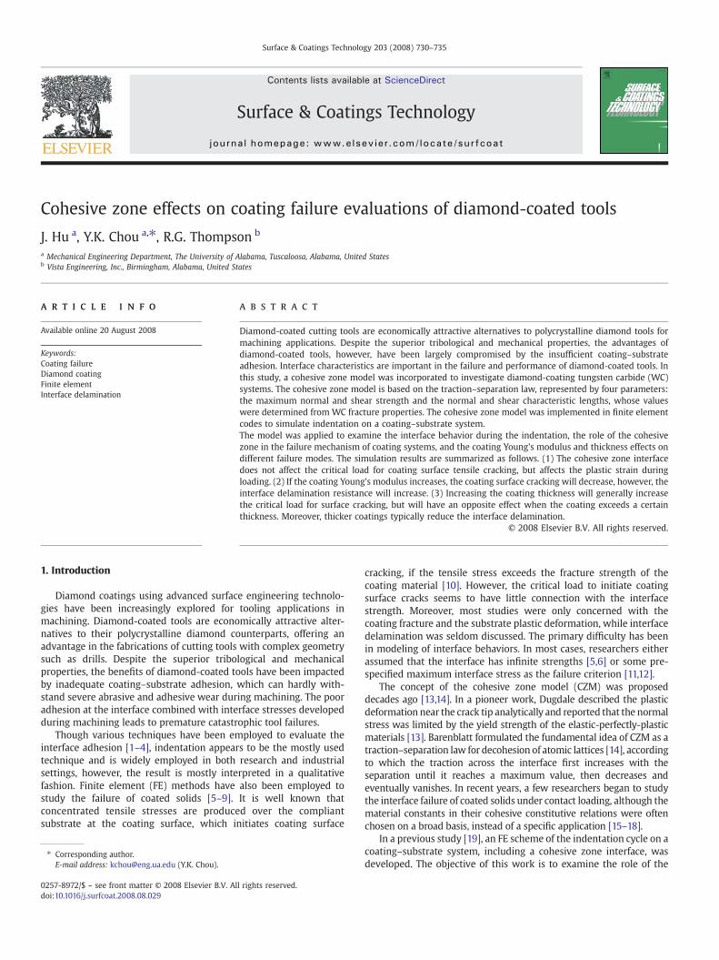
Fig. 2. Shear stress evolution at increasing load: contours of shear stress (30 µm thick, 1200-GPa Young's modulus).
732 J. Hu et al. / Surface & Coatings Technology 203 (2008) 730–735
noticeably vary themodel parameters. In the simulations, thematerialbehaviors were perfect elastic for the diamond coating and elastic–plastic with a hardening rule for the substrate, respectively. Quasi-static structural analysis was performed to simulate the loading–unloading cycle during indentation.
Though diamond–WC indentation has been frequently reported,all data reported are crack and surface damage sizes at discrete loads(limits of Rockwell indentation testing), instead of continuous load-controlled (or displacement-controlled) indentation to monitor thefailure. There is no data from diamond–WC indentation available todirectly validate the model. Since the model was developed withoutspecific material requirements, it should be generic enough to betested by other material systems. Thus, a study of ZnO films depositedon Si substrates with load-controlled indentation tests (Vickersindenter) was used to test the model [24]. The experiments from
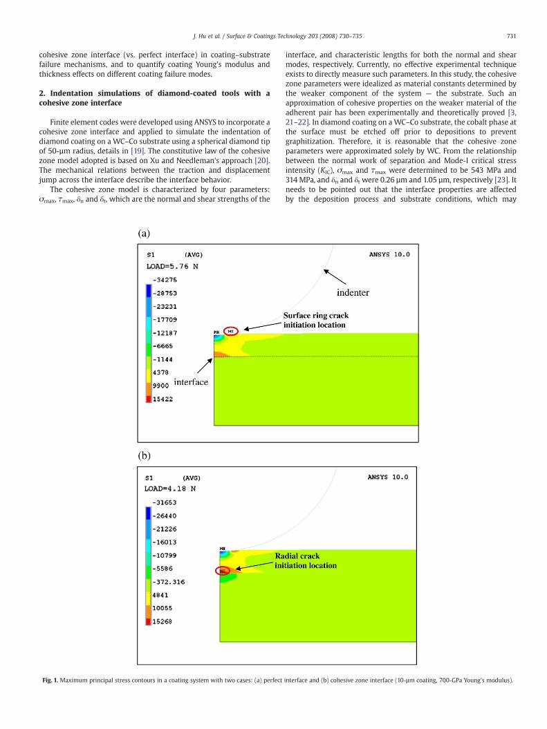
Fig. 3. Response of interface during unloading: normal traction at co
that study reported the critical load for the onset of coatingdelamination at various film thicknesses. The developed FE modelwas thus modified: the indenter shape and size, and the coating andsubstrate materials, to predict the critical load for interface delamina-tion at different thicknesses, which were then compared with theexperiments from [24]. The comparison shows that the relativedifference is 170% in average [19]. Considering the complexity of thecoating failure phenomena and uncertainty in material properties, thetrend and order of magnitude comparisons indicate reasonableagreement.
Once tested, the model was applied to examine the influences ofthe cohesive zone (vs. perfect interface) to critical loads for surfacecracking, and interface delamination at a fixed load. In addition,coating Young's modulus and thickness effects on coating failuremodes were evaluated.
mplete unloading (30-µm coating, 1200-GPa Young's modulus).
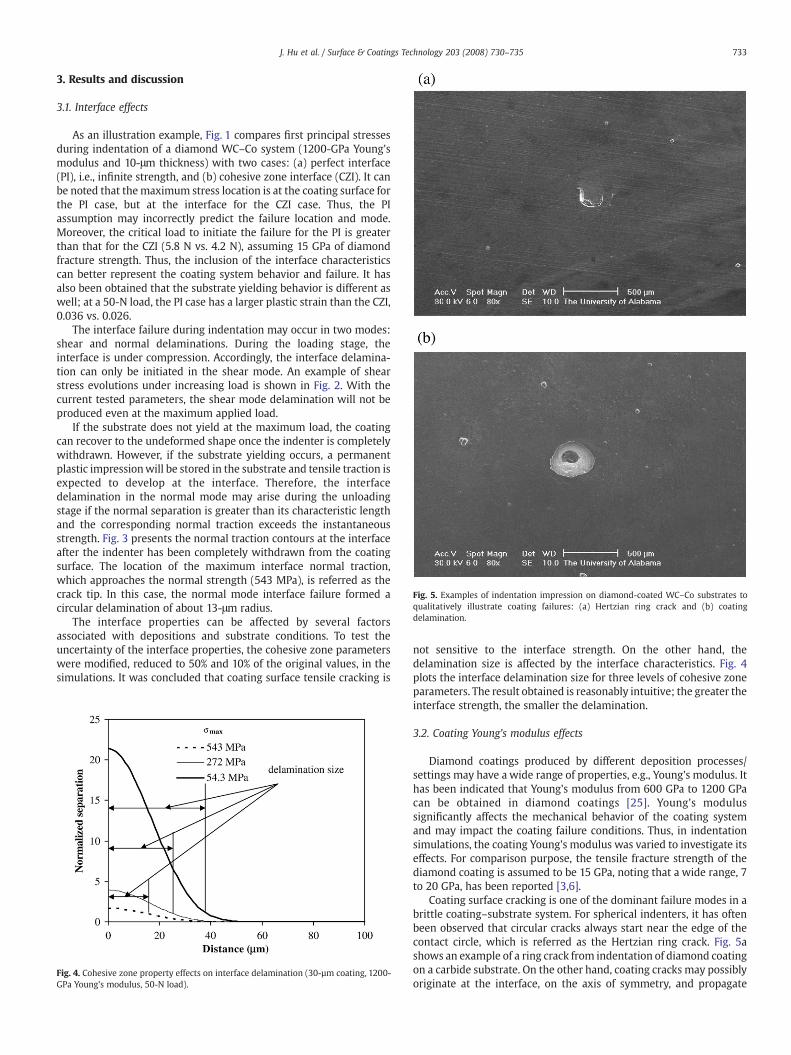
Fig. 5. Examples of indentation impression on diamond-coated WC–Co substrates toqualitatively illustrate coating failures: (a) Hertzian ring crack and (b) coatingdelamination.
733J. Hu et al. / Surface & Coatings Technology 203 (2008) 730–735
3. Results and discussion
3.1. Interface effects
As an illustration example, Fig. 1 compares first principal stressesduring indentation of a diamond WC–Co system (1200-GPa Young'smodulus and 10-μm thickness) with two cases: (a) perfect interface(PI), i.e., infinite strength, and (b) cohesive zone interface (CZI). It canbe noted that themaximum stress location is at the coating surface forthe PI case, but at the interface for the CZI case. Thus, the PIassumption may incorrectly predict the failure location and mode.Moreover, the critical load to initiate the failure for the PI is greaterthan that for the CZI (5.8 N vs. 4.2 N), assuming 15 GPa of diamondfracture strength. Thus, the inclusion of the interface characteristicscan better represent the coating system behavior and failure. It hasalso been obtained that the substrate yielding behavior is different aswell; at a 50-N load, the PI case has a larger plastic strain than the CZI,0.036 vs. 0.026.
The interface failure during indentation may occur in two modes:shear and normal delaminations. During the loading stage, theinterface is under compression. Accordingly, the interface delamina-tion can only be initiated in the shear mode. An example of shearstress evolutions under increasing load is shown in Fig. 2. With thecurrent tested parameters, the shear mode delamination will not beproduced even at the maximum applied load.
If the substrate does not yield at the maximum load, the coatingcan recover to the undeformed shape once the indenter is completelywithdrawn. However, if the substrate yielding occurs, a permanentplastic impressionwill be stored in the substrate and tensile traction isexpected to develop at the interface. Therefore, the interfacedelamination in the normal mode may arise during the unloadingstage if the normal separation is greater than its characteristic lengthand the corresponding normal traction exceeds the instantaneousstrength. Fig. 3 presents the normal traction contours at the interfaceafter the indenter has been completely withdrawn from the coatingsurface. The location of the maximum interface normal traction,which approaches the normal strength (543 MPa), is referred as thecrack tip. In this case, the normal mode interface failure formed acircular delamination of about 13-μm radius.
The interface properties can be affected by several factorsassociated with depositions and substrate conditions. To test theuncertainty of the interface properties, the cohesive zone parameterswere modified, reduced to 50% and 10% of the original values, in thesimulations. It was concluded that coating surface tensile cracking is
Fig. 4. Cohesive zone property effects on interface delamination (30-µm coating, 1200-GPa Young's modulus, 50-N load).
not sensitive to the interface strength. On the other hand, thedelamination size is affected by the interface characteristics. Fig. 4plots the interface delamination size for three levels of cohesive zoneparameters. The result obtained is reasonably intuitive; the greater theinterface strength, the smaller the delamination.
3.2. Coating Young's modulus effects
Diamond coatings produced by different deposition processes/settings may have a wide range of properties, e.g., Young's modulus. Ithas been indicated that Young's modulus from 600 GPa to 1200 GPacan be obtained in diamond coatings [25]. Young's modulussignificantly affects the mechanical behavior of the coating systemand may impact the coating failure conditions. Thus, in indentationsimulations, the coating Young's modulus was varied to investigate itseffects. For comparison purpose, the tensile fracture strength of thediamond coating is assumed to be 15 GPa, noting that a wide range, 7to 20 GPa, has been reported [3,6].
Coating surface cracking is one of the dominant failure modes in abrittle coating–substrate system. For spherical indenters, it has oftenbeen observed that circular cracks always start near the edge of thecontact circle, which is referred as the Hertzian ring crack. Fig. 5ashows an example of a ring crack from indentation of diamond coatingon a carbide substrate. On the other hand, coating cracks may possiblyoriginate at the interface, on the axis of symmetry, and propagate
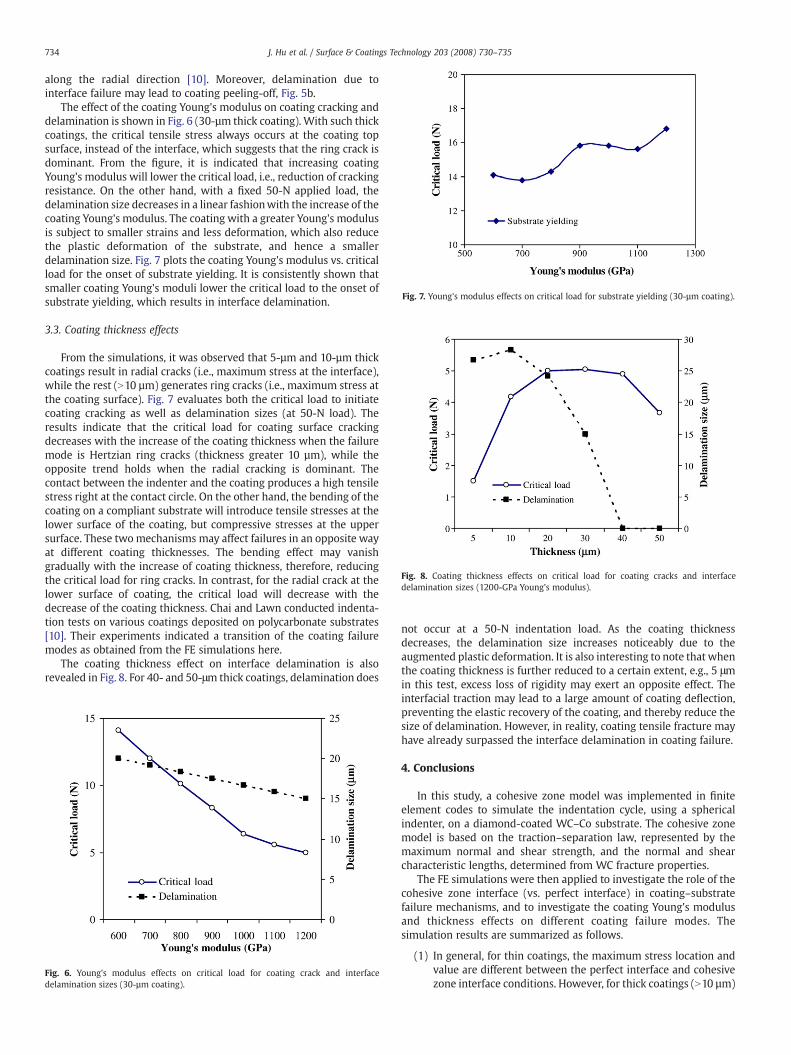
Fig. 8. Coating thickness effects on critical load for coating cracks and interfacedelamination sizes (1200-GPa Young's modulus).
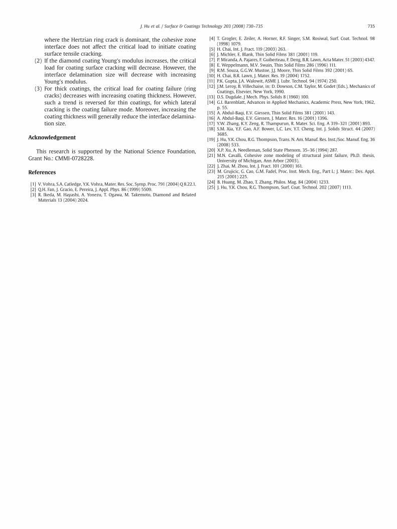
Fig. 7. Young's modulus effects on critical load for substrate yielding (30-µm coating).
734 J. Hu et al. / Surface & Coatings Technology 203 (2008) 730–735
along the radial direction [10]. Moreover, delamination due tointerface failure may lead to coating peeling-off, Fig. 5b.
The effect of the coating Young's modulus on coating cracking anddelamination is shown in Fig. 6 (30-µm thick coating). With such thickcoatings, the critical tensile stress always occurs at the coating topsurface, instead of the interface, which suggests that the ring crack isdominant. From the figure, it is indicated that increasing coatingYoung's modulus will lower the critical load, i.e., reduction of crackingresistance. On the other hand, with a fixed 50-N applied load, thedelamination size decreases in a linear fashionwith the increase of thecoating Young's modulus. The coating with a greater Young's modulusis subject to smaller strains and less deformation, which also reducethe plastic deformation of the substrate, and hence a smallerdelamination size. Fig. 7 plots the coating Young's modulus vs. criticalload for the onset of substrate yielding. It is consistently shown thatsmaller coating Young's moduli lower the critical load to the onset ofsubstrate yielding, which results in interface delamination.
3.3. Coating thickness effects
From the simulations, it was observed that 5-µm and 10-µm thickcoatings result in radial cracks (i.e., maximum stress at the interface),while the rest (N10 µm) generates ring cracks (i.e., maximum stress atthe coating surface). Fig. 7 evaluates both the critical load to initiatecoating cracking as well as delamination sizes (at 50-N load). Theresults indicate that the critical load for coating surface crackingdecreases with the increase of the coating thickness when the failuremode is Hertzian ring cracks (thickness greater 10 µm), while theopposite trend holds when the radial cracking is dominant. Thecontact between the indenter and the coating produces a high tensilestress right at the contact circle. On the other hand, the bending of thecoating on a compliant substrate will introduce tensile stresses at thelower surface of the coating, but compressive stresses at the uppersurface. These twomechanisms may affect failures in an opposite wayat different coating thicknesses. The bending effect may vanishgradually with the increase of coating thickness, therefore, reducingthe critical load for ring cracks. In contrast, for the radial crack at thelower surface of coating, the critical load will decrease with thedecrease of the coating thickness. Chai and Lawn conducted indenta-tion tests on various coatings deposited on polycarbonate substrates[10]. Their experiments indicated a transition of the coating failuremodes as obtained from the FE simulations here.
The coating thickness effect on interface delamination is alsorevealed in Fig. 8. For 40- and 50-μm thick coatings, delamination does
Fig. 6. Young's modulus effects on critical load for coating crack and interfacedelamination sizes (30-µm coating).
not occur at a 50-N indentation load. As the coating thicknessdecreases, the delamination size increases noticeably due to theaugmented plastic deformation. It is also interesting to note that whenthe coating thickness is further reduced to a certain extent, e.g., 5 μmin this test, excess loss of rigidity may exert an opposite effect. Theinterfacial traction may lead to a large amount of coating deflection,preventing the elastic recovery of the coating, and thereby reduce thesize of delamination. However, in reality, coating tensile fracture mayhave already surpassed the interface delamination in coating failure.
4. Conclusions
In this study, a cohesive zone model was implemented in finiteelement codes to simulate the indentation cycle, using a sphericalindenter, on a diamond-coated WC–Co substrate. The cohesive zonemodel is based on the traction–separation law, represented by themaximum normal and shear strength, and the normal and shearcharacteristic lengths, determined from WC fracture properties.
The FE simulations were then applied to investigate the role of thecohesive zone interface (vs. perfect interface) in coating–substratefailure mechanisms, and to investigate the coating Young's modulusand thickness effects on different coating failure modes. Thesimulation results are summarized as follows.
(1) In general, for thin coatings, the maximum stress location andvalue are different between the perfect interface and cohesivezone interface conditions. However, for thick coatings (N10 µm)
735J. Hu et al. / Surface & Coatings Technology 203 (2008) 730–735
where the Hertzian ring crack is dominant, the cohesive zoneinterface does not affect the critical load to initiate coatingsurface tensile cracking.
(2) If the diamond coating Young's modulus increases, the criticalload for coating surface cracking will decrease. However, theinterface delamination size will decrease with increasingYoung's modulus.
(3) For thick coatings, the critical load for coating failure (ringcracks) decreases with increasing coating thickness. However,such a trend is reversed for thin coatings, for which lateralcracking is the coating failure mode. Moreover, increasing thecoating thickness will generally reduce the interface delamina-tion size.
Acknowledgement
This research is supported by the National Science Foundation,Grant No.: CMMI-0728228.
References
[1] V. Vohra, S.A. Catledge, Y.K. Vohra, Mater. Res. Soc. Symp. Proc. 791 (2004) Q 8.22.1.[2] Q.H. Fan, J. Gracio, E. Pereira, J. Appl. Phys. 86 (1999) 5509.[3] R. Ikeda, M. Hayashi, A. Yonezu, T. Ogawa, M. Takemoto, Diamond and Related
Materials 13 (2004) 2024.
[4] T. Grogler, E. Zeiler, A. Horner, R.F. Singer, S.M. Rosiwal, Surf. Coat. Technol. 98(1998) 1079.
[5] H. Chai, Int. J. Fract. 119 (2003) 263.[6] J. Michler, E. Blank, Thin Solid Films 381 (2001) 119.[7] P. Miranda, A. Pajares, F. Guiberteau, F. Deng, B.R. Lawn, ActaMater. 51 (2003) 4347.[8] E. Weppelmann, M.V. Swain, Thin Solid Films 286 (1996) 111.[9] R.M. Souza, G.G.W. Mustoe, J.J. Moore, Thin Solid Films 392 (2001) 65.[10] H. Chai, B.R. Lawn, J. Mater. Res. 19 (2004) 1752.[11] P.K. Gupta, J.A. Walowit, ASME J. Lubr. Technol. 94 (1974) 250.[12] J.M. Leroy, B. Villechaise, in: D. Dowson, C.M. Taylor, M. Godet (Eds.), Mechanics of
Coatings, Elsevier, New York, 1990.[13] D.S. Dugdale, J Mech. Phys. Solids 8 (1960) 100.[14] G.I. Barenblatt, Advances in Applied Mechanics, Academic Press, New York, 1962,
p. 55.[15] A. Abdul-Baqi, E.V. Giessen, Thin Solid Films 381 (2001) 143.[16] A. Abdul-Baqi, E.V. Giessen, J. Mater. Res. 16 (2001) 1396.[17] Y.W. Zhang, K.Y. Zeng, R. Thampurun, R. Mater. Sci. Eng. A 319–321 (2001) 893.[18] S.M. Xia, Y.F. Gao, A.F. Bower, L.C. Lev, Y.T. Cheng, Int. J. Solids Struct. 44 (2007)
3685.[19] J. Hu, Y.K. Chou, R.G. Thompson, Trans. N. Am. Manuf. Res. Inst./Soc. Manuf. Eng. 36
(2008) 533.[20] X.P. Xu, A. Needleman, Solid State Phenom. 35–36 (1994) 287.[21] M.N. Cavalli, Cohesive zone modeling of structural joint failure, Ph.D. thesis,
University of Michigan, Ann Arbor (2003).[22] J. Zhai, M. Zhou, Int. J. Fract. 101 (2000) 161.[23] M. Grujicic, G. Cao, G.M. Fadel, Proc. Inst. Mech. Eng., Part L: J. Mater.: Des. Appl.
215 (2001) 225.[24] B. Huang, M. Zhao, T. Zhang, Philos. Mag. 84 (2004) 1233.[25] J. Hu, Y.K. Chou, R.G. Thompson, Surf. Coat. Technol. 202 (2007) 1113.


![Luxture Surface Coatings Pvt [Autosaved]](https://img.pdfslide.us/doc/110x75/54c0ba8e4a79598c0b8b459a/luxture-surface-coatings-pvt-autosaved.jpg)