Embed Size (px)
Citation preview
May, 1926 INDUSTRIAL AND ENGINEERING CHEMISTRY 471 -
Surface Action and Fluid Film Lubrication‘ Some Film Thickness Measurements
By A. E. Becker
STANDARD OIL Co. (NEW JERSEY), ELIZIBETH, N. J.
To obtain fluid film lubrication there must be adequate adhesive forces between the lubricant and the bearing sur- faces. This indicates four general types of bearing com- binations.
As there is no known method for measuring these ad- hesive forces, the writer has devised apparatus for measur- ing the film thickness developed. This apparatus is de- scribed and data for four oils and four bearing combi- nations are presented.
The general equation for film thickness in terms of load, speed, and viscosity is found to be
where K, A , B, and C are constants depending upon sur- face action forces.
HE part played by surface action in the lubrication problem has become increasingly manifest during T recent years, particularly as regards boundary or
partial lubrication. That these surface forces are also of vital importance in the field of perfect or fluid film lubrication seems to have been overlooked. I n the development of the hydrodynamical theory of lubrication it has been generally assumed that the adhesive forces between the lubricant and the bearing surfaces are always adequate and that fluid film lubrication depends solely upon the viscosity of the lubricant a t the working temperature of the b e a r i n g 4 e., the temper- ature of the film between the bearing surfaces.
From his mathematical analysis Reynolds2 concluded “that with a particular journal and brass the mean thickness of the film of oil would be sensibly constant, and hence, if the vis- cosity was constant, the resistance would increase directly as the speed.’’ But this conclusion was not in accordance with Tower’s3 experiments, in which the resistance increased a t a much slower rate. Accordingly, it appeared to Reynolds that “either the boundary actions became sensible or that there must have been a rise in temperature of the oil which had escaped the thermometer used to measure the tempera- ture of the journal.” Reynolds chose the latter alternative as the explanation of the discrepancy between his theory and experiment.
One of the aims of the present paper is to show that Rey- nolds’ first alternative-namely, the effect of surface or boundary actions-is of prime importance in the formation and maintenance of fluid film lubrication. In a study of this type of lubrication two fundamental principles are obvious:
In order that a fluid film may form in a bearing the lubri- cant must adhere to one or both of the bearing surfaces.
When the adhesive forces and the operating conditions are such to permit fluid film lubrication, the thickness of the film formed is a function of the viscosity of the lubricant a t the working temperature of the film.
It is too much to expect that all lubricants adhere to all bearing surfaces to the same degree or even in amounts such that the adhesive forces are always greater than the cohesive forces within the lubricants. Moreover, it is well known that
(1)
(2)
1 Meeting title, “Effect of Surface Action on Fluid Film Lubrication.” * P h i l . Trans.. 117, 157 (1886). a Proc. I n s f . Mcch. Eng. (London), 1883, 632.
some bearing combinations will stand up under severe oper- ating conditions much more satisfactorily than others. It is also a practical rule in machine design to avoid using the same metal for both elements of a bearing except in a few cases, notably cast iron. A comprehensive study of the ad- hesive forces and crystal structures involved will probably lead to a satisfactory explanation of the reason for these practical rules.
Let us assume the existence of two metals and a lubricant such that the lubricant adheres tenaciously to one of the metals, A , but not a t all to the other, B. Four types of bearings are possible-namely :
(1) The lubricant adheres tenaciously to both bearing ele- ments, A on A.
(2 ) The lubricant adheres to the moving but not to the sta- tionary member, A on B.
(3) The lubricant adheres to the stationary but not to the moving member, B on A . (4) The lubricant does not adhere to either bearing element,
B on B. Method of Measuring Film Thickness
The foregoing analysis of the problem brings out the de- sirability of having some means for determining the mag- nitude of the adhesive forces between lubricants and bearing metals. No satisfactory means for making such measure- ments has yet been devised. Moreover, it is probable that these forces are entirely different in a bearing than for the same bearing surfaces exposed to the atmosphere, since dur- ing use the rubbing action in oil will finally cause the removal of all oxide or other contaminating surface films.
After all, the things of interest are the magnitude of the film of oil which can be maintained in a bearing under given oper- ating conditions and the amount of friction which will be generated. As there are numerous machines for determining the latter quantity the writer directed his attention to de- veloping a method of measuring the former.
Since oil is a good dielectric, a bearing in which fluid film lubrication exists is an electric condenser provided the bear- ing elements are insulated from each other. Since electrical capacity varies inversely as the distance between the plates it becomes a simple matter to calculate the thickness of the oil film from the capacity of such an insulated bearing.
To make such electrical measurements readily plane sur- faces are desirable. It is also obvious that such surfaces can be prepared by polishing more easily than curved surfaces. For these reasons it was decided to use a small thrust bearing for test purposes, despite the fact that a wedge action is considered to be almost indispensable in present-day bearing practice.
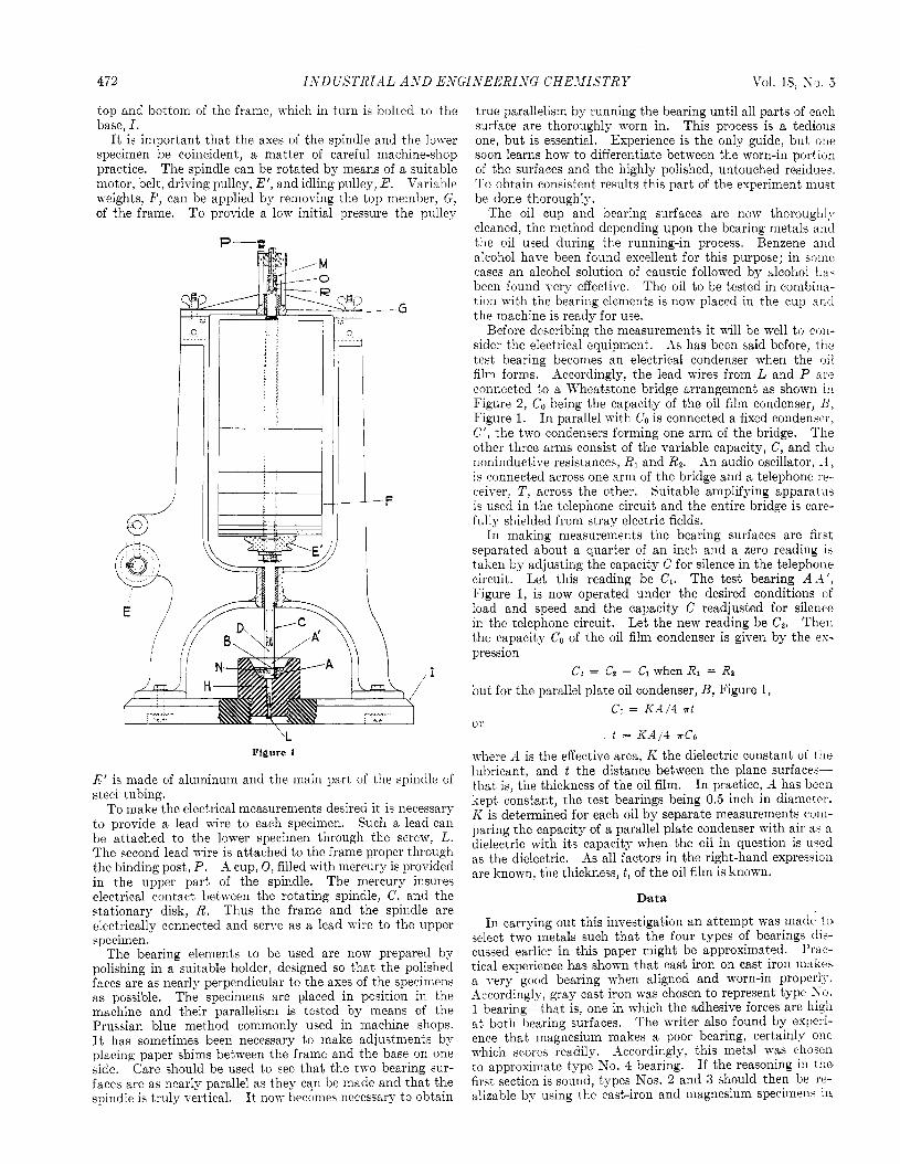
The machine used for making such film thickness measure- ments is shown in Figure l.4 The test bearing consists of two removable elements, A and A’, which can be made of any desired materials. The lower or stationary one, A , is mounted in a bakelite-micarta block, which also acts as an oil reservoir. This block is mounted on a base of the same material. The upper specimen, A‘, is attached to the spindle proper by means of suitable threads and the ground shank, D. The spindle, C, is guided by generous bearings a t the
4 Patents pending.
472 I S D GSTRIilL A N D E,VGI,VEBRISG CHEJI ISTR Y Vol. 18, S o . 3
top and bottom of the frame, which in turn is bolted to the base, I .
It is important that the axes of the spindle and the lower specimen be coincident, a matter of careful machine-shop practice. The spindle can be rotated by means of a suitable motor, belt, driving pulley, E’, and idling pulley, E. Variable weights, F , can be applied by remoring the top member. G, of the frame. To provide a low initial pressure the pulley
/ I
*\\\\\-\\\\v
-- G
-F
‘L Figure 1
E’ is made of aluminum and the main part of the spindle of steel tubing.
To make the electrical measurements desired it is necessary to provide a lead wire to each specimen. Such a lead can be attached to the lower specimen through the screw, L. The second lead wire is attached to the frame proper through the binding post, P. A cup, 0, filled with mercury is provided in the upper part of the spindle. The mercury insures electrical contact between the rotating spindle, C, and the stationary disk, R. Thus the frame and the spindle are electrically connected and serve as a lead wire to the upper specimen.
The bearing elements to be used are now prepared by polishing in a suitable holder, designed so that the polished faces are as nearly perpendicular to the axes of the specimens as possible. The specimens are placed in position in the machine and their parallelism is tested by means of the Prussian blue method commonly used in machine shops. It has sometimes been necessary to make adjustments by placing paper shims between the frame and the base on one side. Care should be used to see that the two bearing sur- faces are as nearly parallel as they can be made and that the spindle is truly vertical. I t now becomes necessary t o obtain
true parallelism by running the bearing until all parts of each surface are thoroughly worn in. This process is a tedious one, but is essential. Experience is the only guide, but one soon learns how to differentiate between the worn-in portion of the surfaces and the highly polished, untouched rez‘d -1 ue i . To obtain consistent results this part of the experiment muqt be done thoroughly.
The oil cup and bearing surfaces are now thoroughly cleaned, the method depending upon the bearing metals aiid the oil used during the running-in process. Benzene a i d alcohol have been found excellent for this purpose; in soine cases an alcohol solution of caustic followed by alcohol ha3 been found very effective. The oil to be tested in combiiia- tion with the bearing elements is now placed in the cup arid the machine is ready for use.
Before describing the measurements it will be well to C(J11-
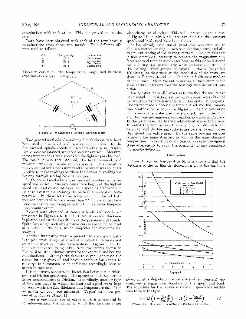
sider the electrical equipment. As has been said before, the test bearing becomes an electrical condenser when the oil film forms. Accordingly, the lead wires from L and P ale connected to a Wheatstone bridge arrangement as shown in Figure 2 , CO being the capacity of the oil film condenser, B , Figure 1. In parallel with CO is connected a fixed condenper. C’, the two condensers forming one arm of the bridge. The other three arms consist of the variable capacity, C, and tlie lioninductive resistances, R1 and R2. An audio oscillator, -4, is connected across one arm of the bridge and a telephone re- ceiver, T , across the other. Suitable amplifying apparatus is used in the telephone circuit and the entire bridge is care- fully shielded from stray electric fields.
In making measurements the bearing surfaces are fii b t separated about a quarter of an inch and a zero reading 1-
taken by adjusting the capacity C for silence in the telephone circuit. Let this reading be C1. The test bearing A l ’ , Figure 1, is now operated under the desired conditions of load and speed and the capacity C readjusted for silence in the telephone circuit. Then the capacity Co of the oil film condenser is given by the es- pression
Cu = CZ - CI when R1 = R1 but for the parallel plate oil condenser, B, Figure 1,
Let the new reading be Cp.
Co = K A / 4 r t
t = KA/4 XCO 01’
where A is the effective area, I< the dielectric constant of the lubricant, and t the distance between the plane surface>- that is, the thickness of the oil film. In practice, A has been kept Constant, the test bearings being 0.5 inch in diameter. I< is determined for each oil by separate measurements com- paring the capacity of a parallel plate condenser with air a” a dielectric with its capacity when the oil in question is uqed as the dielectric. As all factors in the right-hand expres.ioi1 are known, the thickness, t , of the oil film is known.
Data
In carrying out this investigation an attempt was made to select two metals such that the four types of bearings ch- cussed earlier in this paper might be approximated. Prac- tical experience has shown that cast iron on cast iron makey a yery good bearing when aligned and worn-in properly. Accordingly, gray cast iron was chosen to represent type S o . 1 bearing-that is, one in which the adhesive forces are 111g1l a t both bearing surfaces. The writer also found by exiieii- ence that magnesium makes a poor bearing, certain137 one Tvhich scores readily. -%ccordingly, this metal TTas chosen to approximate type S o . 4 bearing. If the reasoning in the first section is sound, types Nos. 2 and 3 should then be le- alizable by using the cast-iron and magnesium specimen. in
May, 1926 ISDCSTRILIL A4AYD E S G I S E E R I S G CHEJIISTRY 473
coinbination with each other. This has proved to be the case.
Data have been obtained with each of the four bearing coinbinations from these two metals. Four different oils were used as follom:
Oil Bi.. gravity CHAR.ACTER '1 23.5 Petroleum R 23.8 Petroleum C 28.5 Petroleum u 2 3 . 1 Prime lard
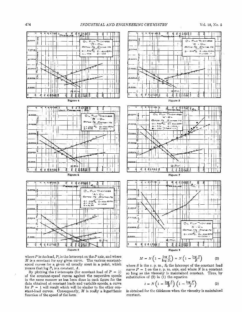
T-iscosity curves for the teniperature range wed in these experiments are given in Figure 3.
"A
Two general methods of obt,aining film t hickriess data have been used for each oil and bearing combinat,ion. In the first method, spindle speeds of 1395 and 400 r. p. m., respec- tively, were maintained, while t'he load was varied. Measure- ment- 15-ere made a t both speeds for the lightest possible load. Tlie machine was then stopped, the load increased, and inc>:isurements again macle a t both speeds. This procedure wa. continued until loads were reached where it, was no longer possible to make readings or where the danger of spoiling the bearing through scoring became too great.
In the second method the load was kept const,ant while the .spt'ed \vas varied. Measurements were begun a t the highest, speed used and continued to as low a speed as practicable in order to assist in maintaining the oil bath at a constant tern- perature. In these tests the teniperature of the oil bath i ~ - a - not permitted to vary more than 2' F., the actual tein- perature maintained being as near 70" F. as room ternpera- t urcs would permit
Typical data obtained a t coilstant loads and speeds are presented in Figures 4 to 10. In these curves film thickness iq plot,ted against the logarit'hms of the pressures and speeds. (&lite frequently such straight-line curves are found to meet
nt on the axis, which siiiiplifies the mathematical
.Inother interesting way to present the data graphically i. t o plot pressure against speed at coiistant thicknesses and conctant viscosities. This has been done in Figures 11 and 12, t h e points plotted being taken from the curves shown in Figures 5 to 10 and similar curves for the other oil and bearing coniliinations. Although the data are as yet inadequat,e the cnrve~ for any given oil and bearing combination appear to converge to a common point and have accordingly been so drawn in each case.
It is of interest to ascertain the relation between film thick- ness and friction generated. The apparatus does not permit direct measurements of friction. AccordingIy, another type of test was made in which the load and speed were kept constant while the film thickness and temperature rise of the oil in the oil cup were measured. Typical data are pre- eented in Figures 13 and 14.
There is one more type of curve which it is essential to consider--namely, the manner in which the thickness varies
Figure 2--Wheatstone Bridge Arrangement
n%h change of viscosity. This is illustrated by the curves of Figure 13. in which all data available for the constant speeds and load; uqecl have been shown.
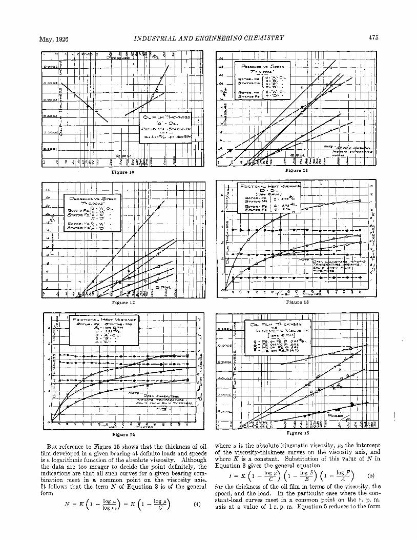
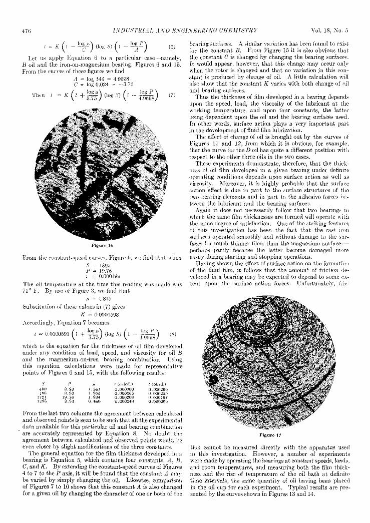
As has already been -tated, great care waq exercised t o ohtaiii a perfect hearing in each combination tezted, and also to prevent qcoring of the bearing surfaces. Deqpite this care it was sometimes necessary to prepare the magnesium sur- face. a qecond time, in some cases because this metal is scored easily during use, particularly when starting and stopping the bearing. Photographs of typical surfaces (magnified 100 times), 3' they were a t the conclusion of the tests, are qhown in Figures 16 and 17. KO etching fluids were used on either wrface. Since the entire bearing surfaces were of the same nature. it follom that the bearings were in perfect con- dition.
The question naturally arises as to whether the results can he repeated. The data presented in this paper were obtained by two of the writer's assistants. A. E. Lee and F. P. Baeyertz. Tlie writer made a check run for the A oil and the iron-on- iron combination as shown in Figure 8. At the conclusion of the work. the wi te r also made a check run for the A oil and the iron-on-magnesium combination as shown in Figure 7. In the latter case, the bearing adjustment was entirely new. It would therefore appear that any one can duplicate the data provided the bearing surfaces are parallel to each other throughout the entire area. By the same bearing surfaces is meant the same structure as well as the same chemical composition. d fairly loose belt tension was used throughout these experiments to avoid the possibility of any complicat- ing spindle deflection.
Discussion
From the curves. Figures 4 to 10, it is apparent that the thickness of the oil film developed in a giren bearing for a
given oil a t a definite oil temperature-i. e., constant vis- cosity-is a logarithmic function of the speed and load. The equations for the curJ-es a t constant speeds are readily seen to be of the type
t = M (1 - -) log P = M ( 1 - log 7) P (1) log Pa (Throughout this paper, logarithms to the base c are used.)
Vol. 18, No. 5 474 INDUSTRIAL A N D ENGINEERING CHEMISTRY
Figure 4
Figure 8
where P is the load, P1 is the intercept on the P axis, and where M is a constant for any given curve. The various constant- speed curves for a given oil usually meet in a point, which means that log P1 is a constant, A.
By plotting the t intercepts (for constant load of P = 1) of the constant-speed curves against the respective speeds in the same manner as has been done in each figure for the data obtained at constant loads and variable speeds, a curve for P = 1 will result which will be similar to the other con- stant-load curves. Consequently, M is really a logarithmic function of the speed of the form
~~
Figure 5
Figure 9
where S is the r. p. m., SO the intercept of the constant load curve P = 1 on the r. p. m. axis, and where N is a constant so long as the viscosity is maintained constant. Thus, by substitution of (2) in (1) the equation
t = N ( 1 -y) (1 - - A (3)
is obtained for the thickness when the viscosity is maintained constant.
May, 1926 INDUSTRIAL A N D ENGINEERING CHEMISTRY 475
Figure 12
Figure 14
But reference to Figure 15 shows that the thickness of oil film developed in a given bearing at definite loads and speeds is a logarithmic function of the absolute viscosity. Although the data are too meager to decide the point definitely, the indications are that all such curves for a given bearing com- bination meet in a common point on the viscosity axis. It follows that the term A' of Equation 3 is of the general form
Figure 11
Figure 13
Figure 15
where p is the absolute kinematic viscosity, the intercept of the viscosity-thickness curves on the viscosity axis, and where K is a constant. Substitution of this value of N in Equation 3 gives the general equation
for the thickness of the oil film in terms of the viscosity, the speed, and the load. In the particular case where the con- stant-load curves meet in a common point on the r. p. m. axis a t a value of 1 r. p. m. Equation 5 reduces to the form
wiiieli i i the equaiion fur the tliickn(:ss of oil filiii dcveloiicti under m y cordition of load, speed, aid viscosity for oil I f and t he tnagnesium-on-iron bearing combination. Using this eqitatioii calculations wviw inadc for repremwt:iti\.e goitits of Figures 6 and 15, witti the following results:
Frotu t he last two coluntiis tlie agreeiiient between ca1i:uI;tted atid oliscrved poiiits is seen to he st ich that all tlie experirririital data nrailable for this particular oil and bearing cotni3iii;itioii are weurately represented by Equation 8. KO doul~t tlia agrecirient hotwren calculated and obwvcd poiuts u;ouhl lie ereii doser by slight modifications of the t.hree constants.
The general equation for the film t,hickness developed iii i i
1)earing is Equation 5 , which contains four consta C, and IC. Uy extending the constant-speed curvcs 4 to 7 to the P axis, it will he found thRt the eoiistaiit it iiixg he varied hy simply changing the oil. Likewise, comparison of Figures 7 to 10 slrowvs that this consbant A is also changed for a gimn oil by changing the character of one or hoth of the
iieariug surfar:es. A ~iitiilar viiriatioii lias been found to esisi for the conslant H. From Figtire 15 it is also obvious that tile constniit C is elrangal 1)y changing the hearing surfaces. It wou11i appear, lionever, that this change may occur mi>- r\-lmi the rotor is changed and that 110 variation in this con- stant is proihiced 1)y change of oil. A little ealculatioir will also show that the eonstnnt K varies 1wsit.h both change oi nil :tiid l>eariiig surfaces.
l'hus the t.1iickness of fihn developed io a hearing depeds upon the speed, load, the viscosihy of the lubricant at the wrrkirtg ternperature, and upon four constants, the latter lieing dependent upim the oil and the bearing surfaew used. In other xvords, surfwe act,iiin plays a wry important part in tlie iieveloptnent of fliiid film lubricatioit.
l 'hc effect of change of oil is brought out by t.lie curves of 1:igures 11 and 12, from which it is obvious, for examplr, that the curre for the D oil has quite a different posibioii witli respect to tlie other tlrree oils in the two cases.
l'licse experiments demonstrate, therefore, that tlie thieh- loped in a given bearing under dctinitc
< I ierating conditions dcpcii i ls upon surface action as wel l :is )sity. Moreover, it is higltly probable that the surfaw ,ti effect is due i n piwt to the surfaa? striieturrs uf the
two be:iriiig clement,s and itt part to t l ie adhesive forces lw- t,ww tlic luhrioant ; + i d tlie hcaririg surlaces.
ApiLiii it does imt, tieccssarily follow that t,wo be:iritig: i n ivlticlt t,he siime filrri ti csses are forincd will oi~erntc i r i t l i t,lto same degrcc of sat iott. Otie OS tlie striking featiirw of t l i i i inrestigatiun lias lbeeti the fact that the , stiritices operated sirirrothly and udliout damage to tlie >iir- fnrci f i n iiiui:li thinrrer films tiran tlrc rniigiiesiwn sitrf:icrs-
11s partly because t,he latter become damaged n iw during EbLrting a i d stopgiiig operations. .ing shown blie effect of surface action oii tlic foriii:iii*m
of thc fluid film, it follows t,lr:it the amount of friation de- re loped in a bearing tmiy he expected t,o depend to m n e VI- tmt i i p ~ i i thc siirfnee artioii forces. Unfnrtuiiately, fric-
Figure 17
tion cannot be rrieasuretl directly with the apparatus i t m l i n t,liis investigation. However, a iturnher of experiments m r c made by operaTing the bearings at constant, speeds, loads, and room temperatures, and nioasuring hoth the tihn thicl;. ncss and the rise of teinperature of the oil bath at definite time intervals, thc: mine quantity of oil having been plncni in the oil cup for each experiment. Typical resuli,s are prc- sentod by the i:iimes s l ioan in Figures 13 and 14.
May, 1926 IiVDLiSTRlAL A S D ESGI,YEERlSG CHEMISTRY 477
In Figure 14 the difference in heating effect for the iron- on-iron bearing caused by increasing the load is very pro- nounced, although fluid film lubrication prevailed a t both loads. Likewise there is only a slightly lower temperature rise for the iron-on-magnesium bearing than for the iron-on- iron bearing, although there is a marked difference in the thickness of film developed, all other operating condition. having remained unchanged. Figure 14 shows how the film thickness and temperature rise may be varied for a given bearing by merely changing the oil to one of different viscoqity.
The investigation has raised many questions, has brought out the fact that fluid film lubrication is materially in- fluenced by surface action, that the friction developed in bearings may accordingly be expected to depend on these surface forces as well as upon viscosity, and that, therefore, a study of bearings according to the four general types discussed in the first section of this paper is highly desirable. I t is expected that different bearings will give different fric- tional results. A more complete mathematical analysis of the experimental data is reserved for a future paper.
Diesel Engine Lubrication By P. L. Scott
‘ 0 SCOTT ST., C l i r C A G O , I L L .
The demands of oil engines, especially those of high power output, make necessary a wide range of pressures, speeds, temperatures, and materials, and it is very im- portant that the proper oil is used. O n elaborate installa- tions several kinds of oil are often used.
Lubricating difficulties in these engines are usually due to failure of the moving parts to get oil, failure of the oil film due to improper design or improper oil, or dirty oil. Ex- plosions due to oil vapor have occurred not infrequently. The oil requirements for the different parts of the engine and the various mechanisms for feeding oil to these vari- ous parts in order to prevent the first two sources of trouble are described. The value of a clean oil is brought out by two illustrations, and several methods for accom- plishing this are suggested.
PICTURE of the practical lubrication problems en- countered by designers and operators of Diesel type oil A engines may be of assistance to the cheinists and oil
refiners on whose continuing cooperation we must rely for their solution.
The demands of the oil engine for steady running at full load are much more severe than on the automobile, and yet it is demanded that it use much less oil. Few automobiles will run 1000 horsepower hours per gallon of oil, assuming proper drainage of crank-case oil. Even the poorest oil engine must do as well as this and most concerns will guarantee 2000 horse- power hours per gallon and some as high as 4000 and 5000 horsepower hours.
The true Diesel antl all engines of high power output, with brake mean effective pressures from 60 to 90 pounds per q u a r e inch require the utmost efficiency in lubrication. Engines using brake mean effectives of 30 or 40 pounds per square inch can use simpler and cheaper systems. The large double-acting two-stroke cycle engine (Figure 1) presents the most serious problem as far as cylinder, piston, and stuffing box are concerned because of the relatively large heat flow. Four-stroke cycle engines add the complication of an elab- orate valve gear, though even when double acting they do not have such seyere heat conditions.
General Lubricating Requirements in an Oil Engine
In an oil engine the following four lubricating demands are to be met: (1) high rubbing velocity with moderate pre- sures, (2) low rubbing velocity with high pressures, (3) low pressures with intense heat, and (4) miscellaneous relatirely small parts lightly loaded as a rule, but requiring a complexity of feeds.
Also the materials moving one upon the other differ widely. This wide range of pressures, speeds, temperatures, and mate- rials would seem to require a dozen different oils, which is ob- viously out of the question. On the more elaborate installa- tions three kinds of oil are used-cylinder oil, crank-case oil, and a light oil for some of the smaller parts. As the require- ments decrease two kinds, and even one, suffice. Too much >tress cannot be laid on the selection of the proper oil.
Common Lubricating Difficulties
Three things may happen as the result of an error in engine operation, design, or selection of oil-the moving parts may fail to get oil; clean oil may break its film too readily; the oil: may be dirty.
The best correction for the first trouble is strict and ade- quate supervision. The second is due to selection of an ini- proper oil and can be corrected by careful study of condition.. The film may fail because the oil will not stand high rubbing- velocity, a high pressure, or a high temperature. The de- signer must keep within known limits in stressing the parts.
Fouling may be caused by dirt in the air, by carbon from the cylinder, by too rapid breaking down of the oil itself, by sapon- ification or emulsion from admixture of water, or by leakage of cylinder oil into the crank case. Dirty oil means rapid wear, burnt bearings, scored cylinders, and often clogging of passage3 so that no oil reaches a given part. The remedy is merely a matter of finding why the oil gets dirty, stopping the cause if possible, and in any event cleaning the oil regularly. Often in overhauling an engine inspection of the oil passages i> neglected, with the result that a piece of waste, or sludge. clogs, and a big repair bill results.
Another cause of serious trouble is explosion of oil vapor in the crank case of a two-stroke cycle crank-case scavenging engine and even in the scavenging belt of pump-scavenged engine. Such explosions have resulted fatally. The writer has had two engines run away on vapor-charged air from the scavenging belt where oil had been allowed to collect. Both cases require that lubrication be sufficient, not in excess.
Figure 2 shows a typical crank-case scavenging engine, antl the method of careful lubrication from a mechanical oiler to a “banjo-ring” in quantities just sufficient to meet the need of the crank pin, and also from this oiler through the cylinder wall into a slot in the piston in quantities just sufficient for the wrist pin. Such engines and the scavenging belt of pump- scavenged engines should be so arranged that they can be drained regularly to remove accumulations.
Figure 3 shows a modification of a piston-scavenging engine, where the problem is not so difficult as with crank-case