Embed Size (px)
Citation preview

Safety FirstIn the maintenance and operation of mechanicalequipment, safety is the basic factor which must be consid-ered at all times. Through the use of the proper clothes,tools and methods of handling, serious accidents causinginjury to you or your fellow workers can be prevented.
Throughout this manual are listed a number of safetyprecautions. Study them carefully and follow them;also insist that those working for you do the same.Remember, an accident is usually caused by someone’scarelessness, neglect or oversight.
Note: Ensure the driven device is properly positionedin its full fail position. If it is not, use theadjustable end of travel stop on the Sure 100(see figure 4) to properly adjust the fail end oftravel stop. Only the fail end of travel may beadjusted. Loosen the lock nut to free theadjusting screw, then use a wrench to turn thescrew. The total adjustment available is +/- 5°.
CAUTION
Loaded spring inside actuator. Do not attempt to repairactuator below top gear plate, unless properly trainedon repair methods.
InstallationNote: SurePowr actuators can be supplied for clockwise
or counter-clockwise spring driven rotation (viewedfrom the top of the actuator). The spring driverotation is noted on the actuator name tag andwiring diagram. Ensure that the actuator hasbeen supplied with the proper spring drive operationfor the application prior to installation on thedriven device.
1. The actuator is shipped in the power off (fail)position. Ensure that the driven device is orientatedto its fail position prior to installation of the actuator.
2. Care should be taken to maintain proper alignmentbetween the actuator and the device shaft. If theactuator is not in the correct alignment with thedevice shaft, repeat the procedure in Step 1.
3. Mount the actuator to the device. Ensure theactuator is centered properly with the device shaft,and then tighten all bolts and nuts evenly.
4. Remove the cover bolts located around theactuator motor and control cover flange.
CAUTION
To prevent ignition of hazardous atmospheres, do notremove actuator cover while circuits are live.
Figure 1
1
5. Terminate field wiring per the appropriate RCSwiring diagram, supplied with the actuator. Usea minimum of #18 AWG stranded wire.
CAUTION
Power circuits are live. Ensure proper precautionsagainst contact to live circuits. Cover the terminal stripwith electrical tape or insulating material to preventcontact with the terminals while working in the actuator.
Switch adjustments for clockwise spring failoperation (viewed from the top of the actuator)
a. Ensure actuator is de-energized and positionedin the clockwise (fail) position. Ensure the endof travel stop is properly adjusted. Rotate thescrew clockwise to move the actuator outputshaft in a counter-clockwise direction. Rotatethe screw in a counter-clockwise direction tomove the actuator output shaft in a clockwisedirection. Loosen the setscrews on Cams 1and 3. Rotate both counter-clockwise until theyclear the switch arm rollers of Switches 1 and 3.
b. Rotate Cam 1 clockwise until it comes incontact with Switch 1’s arm roller and theswitch “breaks”. A light “click” can be heard.Tighten the set-screws on Cam 1.
Surepowr™ Series 100 Installation Manual
e. Upon reaching the opposite end of travel, Cam2 should just engage the roller on Switch 2 sothat the switch just “breaks”. This action willstop the actuator. Check that the actuator hasproperly positioned the driven equipment.
f. If actuator travel is insufficient, rotate Cam 2slightly clockwise until the cam just clears theroller of Switch 2. As soon as the cam clearsthe roller, the actuator will “bump” electricallytowards the end of travel. Continue until theactuator reaches the full end of travel.
g. If the actuator has over-traveled, rotate Cam2 slightly counter-clockwise, then move theactuator towards the fail position electrically.Stop and electrically reverse the direction oftravel. Move the actuator until Cam 2 operatesSwitch 2 and the actuator stops. Repeat thisprocedure until the actuator is properly positioned.
h. Rotate Cam 4 until it comes in contact withSwitch 4’s arm roller and the switch just“breaks”. A light “click” can be heard. Rotatethe cam slightly counter-clockwise. Thisensures that Switch 4 will “break” just priorto the actuator reaching the extreme oppositeend of travel. Tighten the setscrews on Cams2 and 4.
Switch adjustments for counter-clockwise spring failoperation (viewed from the top of the actuator)
a. Ensure the actuator is de-energized andpositioned in the counter-clockwise (fail)position. Ensure the end of travel stop isproperly adjusted. Rotate the screw counter-clockwise to move the actuator output shaft ina counter-clockwise direction. Rotate the screwin a clockwise direction to move the actuatoroutput shaft in a clockwise direction. Loosenthe setscrews on Cams 2 and 4. Rotate bothclockwise until they clear the switch armrollers of switches 2 and 4.
CAUTION
Closely monitor the electrical stroke, as the travel limitswitches are not yet properly adjusted. Ensure the actua-tor does not over-travel and damage driven equipment.
d. Rotate Cam 4 slightly further in the counter-clockwise direction. This ensures that Switch 4will ”break” just prior to the actuator reachingthe full fail position. Tighten the setscrews onCam 4. Energize the actuator. This will movethe actuator to the opposite end of travel.
e. Upon reaching the opposite end of travel, Cam1 should just engage the roller on Switch 1 sothat the switch just “breaks”. This action willstop the actuator. Check that the actuator hasproperly positioned the driven equipment.
f. If actuator travel is insufficient, rotate Cam 1slightly counter-clockwise until the cam justclears the roller of Switch 1. As soon as thecam clears the roller, the actuator will “bump”electrically towards the end of travel. Continueuntil the actuator reaches the full end oftravel.If the actuator has over-traveled, rotateCam 1 slightly counter-clockwise, then movethe actuator towards the fail position electrically.Stop and electrically reverse the direction oftravel. Move the actuator until Cam 1 operatesswitch 1 and the actuator stops. Repeat thisprocedure until the actuator is properlypositioned.
g. If the actuator has over-traveled, rotate Cam 1slightly clockwise, then move the actuatortowards the fail position electrically. Stop andelectrically reverse the direction of travel. Movethe actuator until Cam 1 operates switch 1 andthe actuator stops. Repeat this procedure untilthe actuator is properly positioned.
h. Rotate Cam 3 until it comes in contact withSwitch 3’s arm roller and the switch just“breaks”. A light “click” can be heard. Rotatethe cam slightly further in the clockwisedirection. This ensures that Switch 3 will“break” just prior to the actuator reaching theextreme opposite end of travel. Tighten thesetscrews on Cams 1 and 3.
2
c. Rotate Cam 3 clockwise until it comes in contactwith Switch 3’s arm roller and the switch just“breaks”. A light “click” can be heard.
d. Rotate Cam 3 slightly further in the clockwisedirection. This ensures that Switch 3 will“break” just prior to the actuator reaching thefull fail position. Tighten the setscrews on Cam
3. Energize the actuator. This will move theactuator to the opposite end of travel.
CAUTION
Closely monitor the electrical stroke, as the travel limitswitches are not yet properly adjusted. Ensure theactuator does not over-travel and damage the drivenequipment.
b. Rotate Cam 2 counter-clockwise until it comesin contact with Switch 2’s roller arm and theswitch “breaks”. A light “click” can be heard.Tighten the setscrews on Cam 2.
c. Rotate Cam 4 counter-clockwise until it comesin contact with Switch 4’s arm roller and theswitch just “breaks”. A light “click” can be heard.
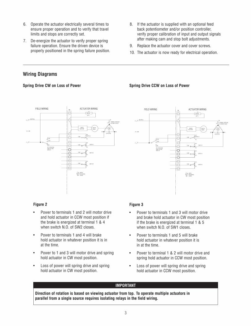
Wiring Diagrams
Spring Drive CW on Loss of Power Spring Drive CCW on Loss of Power
STOP
CCW
CW
SP-3 POSITIONSNAP ACTIONSWITCH
HEATER
11
12
9
7
8 SWITCH 3
NC
NO
3
2
5
4
NC
NC
NO
NO
NC
FIELD WIRING
10
SWITCH 4
NO
ACTUATOR WIRING
SCREW
GREENGROUNDING
M
CAPACITOR
AUTOMATIC RESETTHERMAL OVERLOAD
SWITCH 2
SWITCH 1
L1
A.C. LINE
(NEUTRAL)L2
(OPT.)
1
6
+t∞
MOTORBRAKE
BRIDGERECTIFIER
COM
COM
COM
COM
M1
M2 M3
TB
IMPORTANT
Direction of rotation is based on viewing actuator from top. To operate multiple actuators inparallel from a single source requires isolating relays in the field wiring.
Figure 2
• Power to terminals 1 and 2 will motor driveand hold actuator in CCW most position ifthe brake is energized at terminal 1 & 4when switch N.O. of SW2 closes.
• Power to terminals 1 and 4 will brakehold actuator in whatever position it is inat the time.
• Power to 1 and 3 will motor drive and springhold actuator in CW most position.
• Loss of power will spring drive and springhold actuator in CW most position.
Figure 3
• Power to terminals 1 and 3 will motor driveand brake hold actuator in CW most positionif the brake is energized at terminal 1 & 5when switch N.O. of SW1 closes.
• Power to terminals 1 and 5 will brakehold actuator in whatever position it isin at the time.
• Power to terminal 1 & 2 will motor drive andspring hold actuator in CCW most position.
• Loss of power will spring drive and springhold actuator in CCW most position.
3
SP-3 POSITIONSNAP ACTIONSWITCH
STOP
CCW
CW
HEATER
11
12
9
7
8 SWITCH 3
NC
NO
3
2
5
4
NC
NC
NO
NO
NC
FIELD WIRING
10
SWITCH 4
NO
ACTUATOR WIRING
SCREW
GREENGROUNDING
M
CAPACITOR
AUTOMATIC RESETTHERMAL OVERLOAD
SWITCH 2
SWITCH 1
L1
A.C. LINE
(NEUTRAL)L2
(OPT.)
1
6
+t∞
MOTORBRAKE
BRIDGERECTIFIER
COM
COM
COM
COM
M1
M2 M3
TB
6. Operate the actuator electrically several times toensure proper operation and to verify that travellimits and stops are correctly set.
7. De-energize the actuator to verify proper springfailure operation. Ensure the driven device isproperly positioned in the spring failure position.
8. If the actuator is supplied with an optional feedback potentiometer and/or position controller,verify proper calibration of input and output signalsafter making cam and stop bolt adjustments.
9. Replace the actuator cover and cover screws.
10. The actuator is now ready for electrical operation.
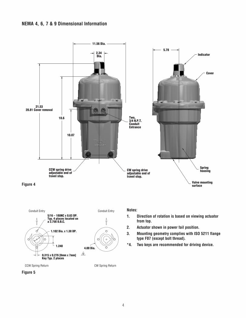
NEMA 4, 6, 7 & 9 Dimensional Information
11.56 Dia.
5.78Indicator
Cover
Springhousing
Valve mountingsurface
2.34Dia.
18.6
10.87
CCW spring driveadjustable end oftravel stop.
CW spring driveadjustable end oftravel stop.
Two,3/4 N.P.T.ConduitEntrance
21.5328.81 Cover removal
Figure 4
Conduit Entry Conduit Entry5/16 – 18UNC x 0.63 DP.Typ. 4 places located ona 2.756 D.B.C.
1.102 Dia. x 1.38 DP.
1.240
0.315 x 0.276 [8mm x 7mm]Key Typ. 2 places
CCW Spring Return CW Spring Return
4.00 Dia.
4
Notes:
1. Direction of rotation is based on viewing actuatorfrom top.
2. Actuator shown in power fail position.
3. Mounting geometry complies with ISO 5211 flangetype F07 (except bolt thread).
*4. Two keys are recommended for driving device.
Figure 5
4
CAUTION
To prevent ignition of hazardous atmospheres, do notremove actuator cover while circuits are live.
OperationPower On: The electric motor drives the gear train, which inturn winds the spring and turns the device. An internal limitswitch de-energizes the motor and the brake, which holdsthe return spring and device in position.
Power Off: When the current is interrupted by either a con-trol signal or a power failure, the return spring drives thedevice to its original position.
Note: It is recommended that the actuator be drivenelectrically in both directions for normaloperation to prolong cycle life.
Maintenance
Gear train is permanently lubricated at the factory for theaverage life of the actuator. No further attention is required.
Thermal Overload
The internal thermal overload switch de-energizes the motorand prevents overheating of the motor windings due toexcessive operation, stalling or high ambient temperatures.
Duty Cycle
The maximum duty-cycle to be expected without interruptionby thermal cut-off at an ambient temperature of 65C° is 25%(3 “OFF” times for every 1 “ON” time) for the 5 and 10 sec-ond design, and 50% (1 “OFF” time for every 1 “ON” time)for the 30 second design.
Storage
The Surepowr actuator must be stored in a clean, dry,temperature controlled building which is protected from theweather. Precautions shall be taken to prevent condensationinside or outside the actuator. If there is insufficient externaltemperature and humidity control, internal heaters must beinstalled and energized to protect the unit against condensa-tion from extreme temperature variations. The actuators shallbe stored off the floor on suitable pallets and must be cov-ered with an unsealed dust protector allowing side andbottom ventilation.
Isolation Relays
To operate multiple actuators in parallel from a single signalrequires isolating relays in the field wiring. Consult Factory.
Troubleshooting (New Unit)Note: Most actuator problems occur due to incorrect
cam/travel limit switch setting, or the use ofan external travel stop on the device that theactuator is operating.
Problem 1: Actuator is receiving electric power butthe motor does not respond.
Instructions:
1a. Check actuator nameplate to insure correctmodel, voltage type and spring return direction.
1b. Check all wiring against installationwiring diagram.
1c. Actuator with clockwise fail position:Using a volt meter, check that power isavailable between terminals 1 and 2. Thencheck the voltage between terminal 1(common) and the two legs of the motor andcapacitor. The meter should indicate a valueequal to or greater than the supply voltageindicated on the actuator nametag.Actuator with counter-clockwise fail position:Using a volt meter, check that power isavailable between terminals 1 and 3. Thencheck the voltage between terminal 1(common) and the two legs of the motor andcapacitor. The meter should indicate a valueequal to or greater than the supply voltageindicated on the actuator nametag.
If power is not present at the motor or capacitor leads:
• Cam adjustments are required
• Switch malfunction
• Improper wiring
5
Problem 2: Actuator is receiving electric power butthe motor only hums.
Instructions:
2a. Perform steps 1a through 1c listed above.
2b. Check to insure the brake is completelydisengaged when power is applied.
Problem 3: Actuator runs but operation is erratic.
Instructions:
3a. Perform steps 1a through 1c listed above.
3b. Check ambient temperature. StandardSurepowr actuators have a maximum ambientoperating temperature rating of 65°C.
3c. Check duty cycle (frequency of operation).See above for details.
3d. Ensure that actuator is not continuouslystalled.
Problem 4: Motor runs continuously in springreturn direction after actuator outputshaft has stopped.
Instructions:
4a. Adjust spring return side travel cam/switch sothat the cam trips the switch before the shaftstops motion.
Problem 5: Motor runs continuously but outputshaft does not turn.
Instructions:
5a. Check for power to the bridge rectifier andclutch solenoid.
Note: Standard Surepowr actuators are manufactured withthermal overload protectors in series with the motorcommon. Should any of the above problems causethe protector to open, it will automatically resetwhen the motor temperature is lowered to asafe level.
Locating and Ordering PartsFor ease and accuracy in identifying and ordering spare orreplacement parts, submit the following information fromunit nameplate.
1. Serial Number
2. Model Number
3. Voltage
Surepowr Series_100_im7.08
©2008 Dresser, Inc.RCS, and DRESSER are registered trademark(s) of Dresser, Inc.
Industrial Products GroupDresser, Inc.16240 Port Northwest DriveHouston, Texas 77041-2645 USAPh: 832.590.2306 Fax: 713.849.2879Toll Free Phone: 800.945.9898 Email: [email protected]
www.dresser.com