Embed Size (px)
Citation preview
Supporting mobility in an IMS-based P2P IPTV
service: a Proactive Context Transfer mechanism
Ivan Vidala,∗, Jaime Garcia-Reinosoa, Antonio de la Olivaa, Alex Bikfalvib,Ignacio Sotoa
aUniversidad Carlos III de Madrid. Avda. de la Universidad 3028911 Leganes - Madrid (Spain)
bIMDEA Networks, Avda. del Mar Mediterraneo 22, 28918, Leganes - Madrid (Spain)
Abstract
In recent years, IPTV has received an increasing amount of interest from theindustry, commercial providers and the research community, alike. In thiscontext, standardization bodies, such as ETSI and ITU-T, are specifying thearchitecture of IPTV systems based on IP multicast. An interesting alter-native to support the IPTV service delivery relies on the peer-to-peer (P2P)paradigm to distribute and push the streaming effort towards the networkedge. However, while P2P IPTV was studied in fixed access technologies,there has been little attention paid to the implications arising in mobile en-vironments. One of these involves the service handover when the user movesto a different network. By analyzing previous work from the perspective ofan IPTV service, we concluded that a proactive approach is necessary for thehandling of inter-network handovers. In this paper, we propose a new generalhandover mechanism for the IP Multimedia Subsystem (IMS), while study-ing its applicability to a P2P IPTV service. Our solution, called ProactiveContext Transfer Service, incorporates the existing IEEE 802.21 technologyin order to minimize the handover delay. The proposal is validated by com-paring it against solutions derived from previous work.
Keywords: IP Multimedia Subsystem (IMS), Peer-to-Peer (P2P), MobileIP (MIP), Television over IP (IPTV), IEEE 802.21
∗Corresponding authorEmail addresses: [email protected] (Ivan Vidal), [email protected] (Jaime
Garcia-Reinoso), [email protected] (Antonio de la Oliva), [email protected](Alex Bikfalvi), [email protected] (Ignacio Soto)
Preprint submitted to Computer Communications April 29, 2010

1. Introduction
Nowadays there are several initiatives and research studies proposinga general architecture to stream TV using the TCP/IP protocols (IPTV)([1, 2]). As the applicability of IP multicast in the current Internet presentsseveral challenges [3], such as address management, security, support of het-erogeneous receivers and charging, other proposals are gaining support forcontent distribution to multiple users. One of these alternatives is the use ofPeer-to-Peer (P2P) techniques to distribute content, by means of an overlaynetwork formed by end user equipment [4]. One of the challenges with thistechnique in the current Internet is how to distribute a real-time flow over abest-effort network: although there are very efficient ways to construct theoverlay and to exchange packets between end nodes, packets can be delayedor lost.
In order to guarantee an acceptable Quality of Service (QoS), some im-provements are necessary to the Internet. In this context, standardizationbodies like 3GPP and ETSI (TISPAN working group) are working to proposea complete architectural framework for Next Generation Networks (NGNs),capable of providing QoS to end-users. NGNs are centered around the IPMultimedia Subsystem (IMS), which provides access and session control forall-IP services. Initially developed by 3GPP for UMTS cellular networks,currently 3GPP is working together with ETSI-TISPAN to extend the spec-ification for any type of access technology.
In [5], the authors propose a way to deploy P2P IPTV streaming usingIMS as the core of the system, providing mechanisms to join, switch betweenchannels and leave the system with similar delays as in the IP multicastcounterpart. A brief introduction to the IMS and this P2P IPTV systemis included in Sect. 2. In this proposal all peers are connected to a fixedaccess network, therefore we decided to explore the impact of user mobility
in the previously proposed system. There are two problems when using mobiledevices as peers in a P2P IPTV system: (1) limited uplink bandwidth and(2) packets losses while switching between different networks (changing theIP address).
Section 3 analyses how to enable mobility for the P2P IPTV service, usingcurrent proposals for handover across IMS networks, and proposes a bufferingmechanism to avoid packet losses. In Sect. 4 we propose a mechanism to
2

minimize the handover delay by transferring in advance, before the UserEquipment (UE) moves, the IMS context between the serving and targetnetworks, hence reducing the number of operations performed during thehandover. To this end, we use the IMS infrastructure and we introduceIEEE 802.21 signalling, minimizing the changes to current specifications.Although this is a general proposal that can be used for any multimediaservice, in order to estimate the desired delays, this section particularizeshow this architecture can be used in a P2P IPTV scenario. Because thedelay imposed by a mobility solution is critical for an IPTV service, Sect. 5is focused on its analytical measurement for the solutions presented in Sect. 3and Sect. 4. Section 6 concludes with the most remarkable points discussedin the paper, and presents the future work.
2. Background on the IMS-based P2P IPTV service
This section presents a brief description of the architecture, technologiesand protocols used in the IP Multimedia Subsystem (IMS). In addition, weprovide an overview of the P2P IPTV service [5] built on top of the IMS.
2.1. The IP Multimedia Subsystem
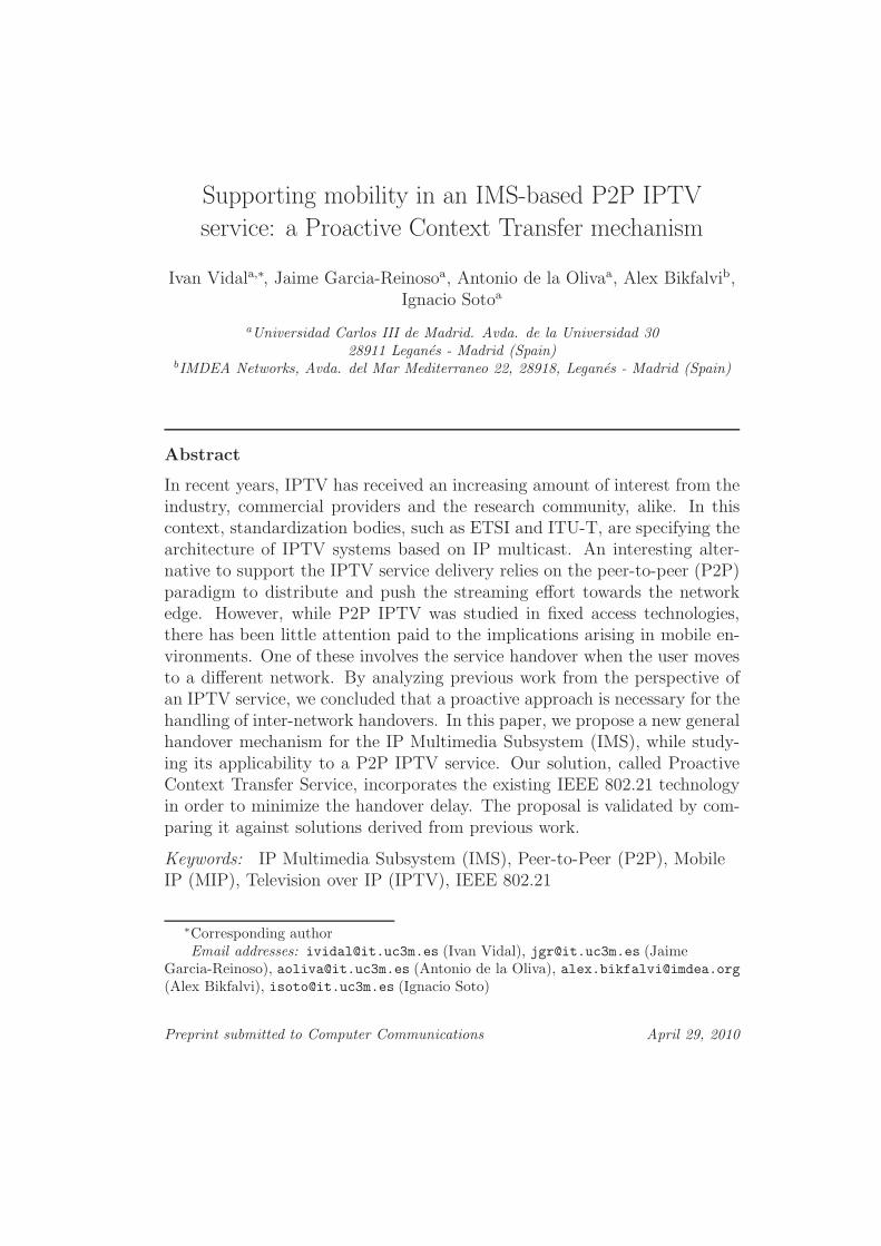
Nowadays, the Internet and the cellular networks evolve towards conver-gence, integrating a broad set of services that are delivered to the end userby means of the IP protocol. In this context, the IP Multimedia Subsys-tem (IMS) is currently being developed by the 3GPP as a key element tofacilitate the convergence. The IMS is a control architecture, based on theIP protocol, that enables the provision of value-added multimedia servicesby supporting a set of facilities related with session control, QoS, chargingand integration of services. Figure 1 shows a simplified overview of the IMSarchitecture (further details can be found in [6]), where a User Equipment(UE) gets network connectivity by means of a UMTS access1, consisting ofa UMTS terrestrial radio access network and the UMTS packet domain.
As it can be observed from the figure, the architecture follows a layeredapproach, where three planes have been defined: the control plane, the user
plane and the application plane. This organization allows to separate thetransport technologies and bearer services, utilized at the transport plane,
1Note that IMS can also be used with other access network technologies.
3
Gm
d
CSCFs
UTRAN
AS
UE
ISC
Mw
Rx
Mw
Gi
Gn Gi IP network
P-CSCF
SGSN
PCRF
Go
Control
plane
User
plane
Application
plane
Cx
S-CSCF
Dx
Dx
HSS
GGSN
Cx
I-CSCF
Sh
SLF
Figure 1: IMS architecture
from the session management functionalities that correspond to the controlplane. On top of the control plane, the application plane implements theservices that are accessed by the end user. These services are provided witha set of common functionalities from the control plane, and can be deliveredto the end user independently from the network access technology utilized inthe user plane. In this layered architecture, the Session Initiation Protocol(SIP) [7] plays a crucial role, being the protocol chosen in the IMS for ses-sion control functionalities. In addition to SIP, other protocols are speciallyrelevant in the IMS such as Diameter [8], that is utilized to provide AAA(Authentication, Authorization and Accounting) functionalities.
On the other hand, the different functions implemented at each plane areorganized in a set of functional entities, which are interconnected by stan-dardized reference points. Focusing on the control plane, the following enti-ties are specially relevant: the Call Session Control Functions (CSCFs), whichare in charge of processing all the SIP signaling messages originating or ter-minating at the UE; the user databases, namely the Home Subscriber Server(HSS) and the Subscriber Location functions (SLF); and the Policy Controland Charging Rules Function (PCRF), which provides policy control decision
4

and flow-based charging control functionalities. The IMS architecture definesthree types of CSCFs: the Proxy-CSCF (P-CSCF), the Interrogating-CSCF(I-CSCF) and the Serving-CSCF (S-CSCF). The P-CSCF is the entry/exitpoint into the IMS control plane for every SIP signalling message originat-ing/terminating at the UE. The I-CSCF is the entry point to the network ofan operator for the incoming sessions destined to the operator subscribers.The Serving-CSCF (S-CSCF) performs session control and registration func-tionalities. This functional entity checks the service profile of the user andverifies whether a given SIP signalling message should be routed to one ormore Application Servers (ASs), which provide services to the end user (e.g.IPTV) from the application plane.
In the user plane, Fig. 1 shows the UMTS Terrestrial Radio Access Net-work (UTRAN) and the UMTS packet domain. The latter includes the Serv-ing GPRS Support Node (SGSN), that links the radio access network withthe packet core network, and the Gateway GPRS Support Node (GGSN),that internetworks with external networks and provides the UE with IP-levelconnectivity by means of PDP contexts. A Packet Data Protocol (PDP)context is a QoS enabled logical connection that supports the exchange ofIP packets between the UE and the GGSN.
2.2. P2P streaming in IMS
This section presents the architecture proposed in [5]: a peer-to-peerIPTV service in a fixed IMS scenario, where the video streaming is doneusing Application Level Multicast (ALM) trees (one tree corresponds to oneTV channel). A tree is built between the video server (or IPTV head-end) andone or more UEs, which, in turn, can be used as a normal server to distributethe video stream to other UEs. The overall architecture is presented in Fig.2.
The weakness point in ALM is the disruption of the service when a parentnode (a node serving video to other peers) leaves the tree: all branches belowthe leaving node will be affected until the tree is completely reconstructed.A node leaves a tree when tuning to a different channel or when leaving thesystem. The former is a controlled action and the system can react tryingto minimize packet losses. When switching between channels there are twoparameters that have to be taken into account: packet losses for the orphanchildren and the channel switching time for the leaving node. In case of anordered or a non-ordered leaving the only thing that has to be considered isthe number of lost packets.
5

UE
Service layer
UE
UE
UE
UE
UE
UE
IMS IPTV-AS
Transport layer
SIP signaling
Media connection
Media
Server
Figure 2: P2P IPTV service architecture
MSCh1
P4
Ch1
Foster peer
P5
Ch1
P2
Ch1
P1
Ch1
P3
Ch1
PF
Ch2
P1
Ch1
P4
Ch1
P3
Ch1
P5
Ch1
PF
Ch2
P2
Ch2
MSCh2
MSCh1
MSCh2
Fast tree reconstruction
Fast channel change (from channel 1 to channel 2)
Figure 3: Fast channel change
As reconnecting to the tree through the IMS implies a long delay, [5]introduces the concept of foster peers, which are peers with pre-reservedresources that can quickly accept orphan children or peers switching to theirchannels. In case of a channel change, orphan peers will be reconnected tofoster peers in the same tree and then the leaving peer will be associatedwith a foster peer in the desired channel (see Fig. 3). In case of an orderedleaving, orphan peers will be rehoused in the same way as in the switchingchannel process and then the leaving node will be authorized to disconnect.For a non-ordered leaving, the process is the same but it will be triggered bya timer or a counter for packet losses at the orphan nodes instead of by theleaving node.
Another key entity introduced in [5] is the IPTV Application Server orIPTV AS. The IPTV AS is a SIP Application Server, used as a Back-to-Back
6
User Agent2 (B2BUA) between two UEs or between a Media Server and aUE. The SIP signalling involved in the ALM construction and maintenancepasses through the IPTV AS. The IPTV AS receives SIP messages in orderto tune to a channel, switch between channels and leave the system. With allthis information, the IPTV AS decides how to construct or modify all treesin the system, adding and removing foster peers when necessary.
Although the main ideas described in [5] can be used for fixed or mobileUEs, there are two problems that must be addressed when the UE is a mobiledevice:
• In a wireless environment, the access bandwidth is a scarce resource. Ingeneral, the uplink should not be used by the UE in order to minimizecosts and improve the resource usage.
• If a mobile UE changes its IP address while receiving a stream, packetswill be lost. The number of lost packets depends on the delay intro-duced during the handover.
The first issue can be easily addressed at the IPTV AS. As this is the func-tional entity in charge of setting up the distribution tree, it can guarantee thata mobile UE never assumes the role of a parent peer in the tree. Regardingthe second issue, it is possible to classify handovers in two groups: soft han-
dovers (make-before-break) and hard handovers (break-before-make). Whilein soft handover the same data is delivered to the mobile device through twoaccess networks simultaneously, in hard handover data is always received inone and only in one interface at any time. Although there are some studiesusing soft handover mechanisms like in [9], our goal is to propose a more gen-eral mechanism valid for any kind of mobile devices. Therefore, next sectionswill focus on minimizing the number of lost packets using a hard handover
approach.
3. Enabling seamless mobility in the P2P IPTV service
As it has been indicated in the previous section, enabling mobility inthe P2P IPTV service entails packet losses in the media plane. As long
2A Back-to-Back User Agent (B2BUA) is a concatenation of two SIP User Agentsconnected by some application-specific logic (see [7]). A B2BUA receives SIP requests,and to determine how each request should be responded it can generate further requests.
7

bursts of packet losses can negatively influence the end user experience, somemechanisms are needed to address this issue. In this respect, we propose tocombine the following two approaches:
• Introducing buffering techniques at the parent peer (if delay is stillsignificant).
• Minimizing the handover delay of the mobile UE.
In the following we cover each of these two approaches, buffering tech-niques are analyzed in section 3.1 while section 3.2 analyses the handoveralternatives that have been proposed in the literature for IMS enabled net-works.
3.1. Buffering packets when roaming in IMS
Video streaming is a real-time application, sensitive to jitter and longbursts of lost packets. The jitter problem can be mitigated using bufferingat the client side, introducing a delay in the play-back process, which canbe tolerated by the user if it is not too high. Low packet losses can also betolerated by the user. The problem arises when a high number of packets arelost due to mobility. In order to minimize packet losses, we propose to senda pause to the parent of the moving UE before it starts the handover. Afterthe UE is stable in the new access network, it sends a resume to its parentwhich, in turn, resumes sending the buffered packets at the maximum peakrate. Appropriate buffering at the mobile node side makes the proceduretransparent to the users.
Let us denote the delay introduced during the handover process by d,and the bit rate of the video (assuming a Constant Bit Rate or CBR) byR. Then, it is possible to express the total number of bits buffered at theparent while its child is in the handover process as b = d × R. When themobile node finishes the handover by sending a resume message, the parentwill restart sending all buffered packets and all incoming packets during therecovery phase. In our approach, the parent will send packets at the videobit rate (R) and an additional bandwidth (Radd) to recover the original buffersize at the mobile node (the total bandwidth during the recovery phase isthen R + Radd). The delay dr necessary to recover the stored buffer at themobile node is dr = b/Radd. With the former and the latter equalities, wecan obtain Eq. 1 that will be used in Sect. 5 in order to obtain representativerecovery delays.
8
dr =d × R
Radd
(1)
The handover delay depends on the specific scenario used for mobility inIMS. These scenarios will be described in the next subsection and the delayintroduced for each scenario will be analyzed in Sect. 5.
3.2. Alternatives for UE mobility in an IMS-based IPTV service
There has been a huge effort to improve mobility management in IPnetworks. Standardization bodies such as the Internet Engineering TaskForce (IETF) have developed solutions for mobility support in IPv4 [10] andIPv6 [11], for improved IP handover performance [12, 13], and for supportingthe movement of networks as a whole [14]. Researchers have also addressedthese topics with different points of view ([15, 16, 17, 18, 19, 20]). However,macro-mobility (changing network and IP address) in IMS-based networksis very difficult to achieve with existing standards [21], although this type ofmobility is expected to become very common. The challenges of integratingmobility, IMS, and control of the access network have been analyzed in [22](WLAN and cdma2000 access) and in [23] (GPRS access).
This section presents three existing handover mechanisms for IMS-basedservices, particularizing to the P2P IPTV service and to the use of the buffer-ing mechanism defined in Sect. 3.1. From now on we assume that the UE isconnected through a GPRS access network3, but the studied mechanisms areapplicable to any IMS based network and access technology, except that theprocedure for reserving resources in the access network would be different.
Next we introduce several general notions belonging to the IMS andGPRS technologies. In a general mobility scenario, the UE can be locatedeither in the home or in the visited network. The home network maintainsthe user subscription data and provides services. In general, we assume thatthe UE moves from an old (or current) to a new (or target) network, whereboth the old and the new network can be the home or a visited network. Inaddition, the entry-point for the IMS, the Proxy Call Session Control Func-tion (P-CSCF), can be located either in the home or in the visited network,
3We use the term GPRS access network to refer to the packet domain of UMTS net-works plus the radio access network
9
P-CSCF
IMS core
UE
Gm
P-CSCF
IMS core
Gm
IMS core
ISC
HSS
Mw
Mw
IPTV AS
Cx
Old network New network Home network Other network
P-CSCF
Correspondent
network
CN
Access
network
Access
network
Handover
Mw
Access
network
UE
P-CSCF in the
home network
P-CSCF in the
visited network
Gm Gm
IMS core
S-CSCF
HA
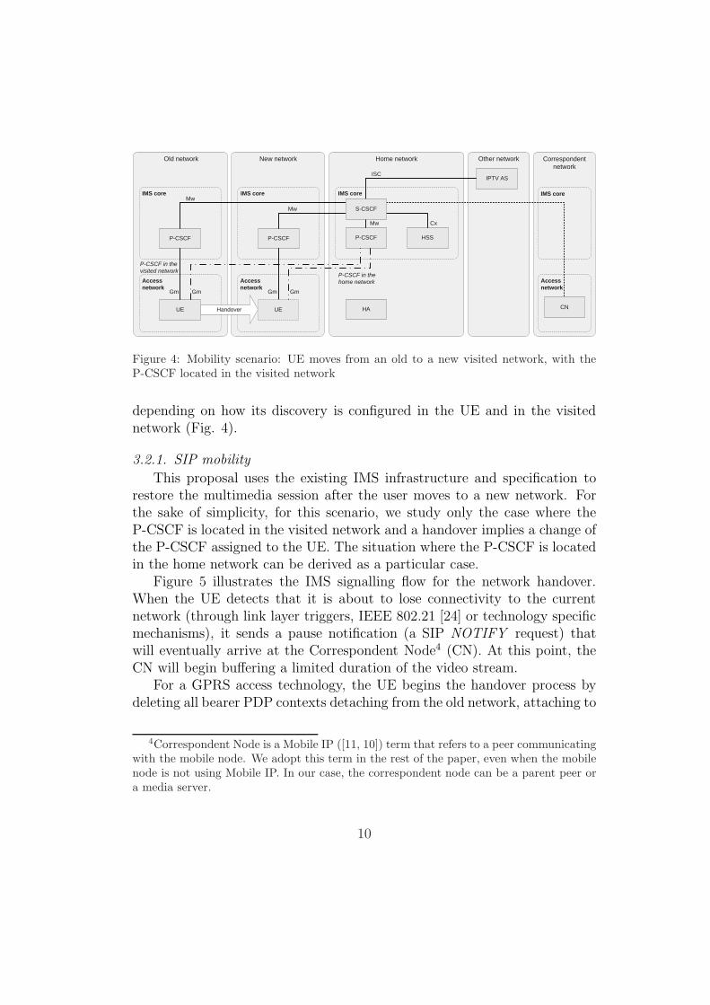
Figure 4: Mobility scenario: UE moves from an old to a new visited network, with theP-CSCF located in the visited network
depending on how its discovery is configured in the UE and in the visitednetwork (Fig. 4).
3.2.1. SIP mobility
This proposal uses the existing IMS infrastructure and specification torestore the multimedia session after the user moves to a new network. Forthe sake of simplicity, for this scenario, we study only the case where theP-CSCF is located in the visited network and a handover implies a change ofthe P-CSCF assigned to the UE. The situation where the P-CSCF is locatedin the home network can be derived as a particular case.
Figure 5 illustrates the IMS signalling flow for the network handover.When the UE detects that it is about to lose connectivity to the currentnetwork (through link layer triggers, IEEE 802.21 [24] or technology specificmechanisms), it sends a pause notification (a SIP NOTIFY request) thatwill eventually arrive at the Correspondent Node4 (CN). At this point, theCN will begin buffering a limited duration of the video stream.
For a GPRS access technology, the UE begins the handover process bydeleting all bearer PDP contexts detaching from the old network, attaching to
4Correspondent Node is a Mobile IP ([11, 10]) term that refers to a peer communicatingwith the mobile node. We adopt this term in the rest of the paper, even when the mobilenode is not using Mobile IP. In our case, the correspondent node can be a parent peer ora media server.
10

Up
da
te
pe
er
se
ssio
n
Re
-re
gis
ter
with
ne
wIP
ad
dre
ss
Re
su
me
ch
an
ne
l
Pa
use
ch
an
ne
l
Re
-in
vite
P-CSCF ANUE AN ANP-CSCF S-CSCF IPTV-AS CN
NOTIFY (pause)
OKOK
New network Old network Home network
REGISTER REGISTER
200 OK200 OK
INVITE
Media stream (to old IP address)
Pause streaming and
start media buffering
INVITE INVITE
183 Session progress183 Session progress183 Session progress
PRACK PRACK PRACK
200 OK200 OK200 OK
200 OK200 OK200 OK
ACK ACK ACK
200 OK
Media stream (to new IP address)
NOTIFY (pause) NOTIFY (pause)
OK OK
NOTIFY (pause)
Correspondent network
200 OK 200 OK 200 OK
UPDATE UPDATE UPDATE UPDATE
NOTIFY (resume)
OKOK
NOTIFY (resume) NOTIFY (resume)
OK OK
NOTIFY (resume)
Delete old PDP contexts
Activate primary PDP context
401 Unauthorized 401 Unauthorized
REGISTER REGISTER
Activate secondary PDP context
Modify secondary PDP context
Move to new network
Figure 5: SIP mobility with the P-CSCF located in the visited network
11
the new network and establishing a primary PDP context for IMS signalling.With the activation of a new PDP context, the UE obtains a new IP addressand discovers a P-CSCF in the new network. Afterwards, the UE initiatesa regular IMS re-registration procedure, to inform the S-CSCF of the newcontact address and P-CSCF address. This procedure is completed in theusual way after two round trips, each of them initiated by a REGISTERrequest. Further details on the IMS registration procedure can be found in[25].
Following a successful re-registration, the UE modifies the existing IPTVsession by issuing a re-INVITE via the new P-CSCF. During the re-INVITE,the IPTV AS updates the contact URI of the UE, the URI of the new P-CSCF
and the IP address and port where the media stream will be delivered. Inaddition, the UE performs a resource reservation by establishing a secondaryPDP context. After the secondary PDP context is activated, the UE sendsa SIP UPDATE request towards the IPTV AS that, in turn, arrives at theCN updating the destination IP address and port. Finally, the UE sends aNOTIFY that eventually arrives to the CN to resume the video streaming.
For the mobility scenario to work, the IPTV application at the UE mustexecute the signalling procedures described here and preserve the state ofthe existing SIP sessions during the handover (while network connectivity islost).
3.2.2. Optimised SIP mobility
As an improvement over the previous mobility scenarios, several paperslike [23, 26, 27] have proposed an optimization technique that transfers thecontext information between the old and new P-CSCF. The purpose of theP-CSCF context transfer is to reduce the handover latency by having all theparameters necessary to establish the signalling security associations and thebearer PDP context readily available at the new P-CSCF.
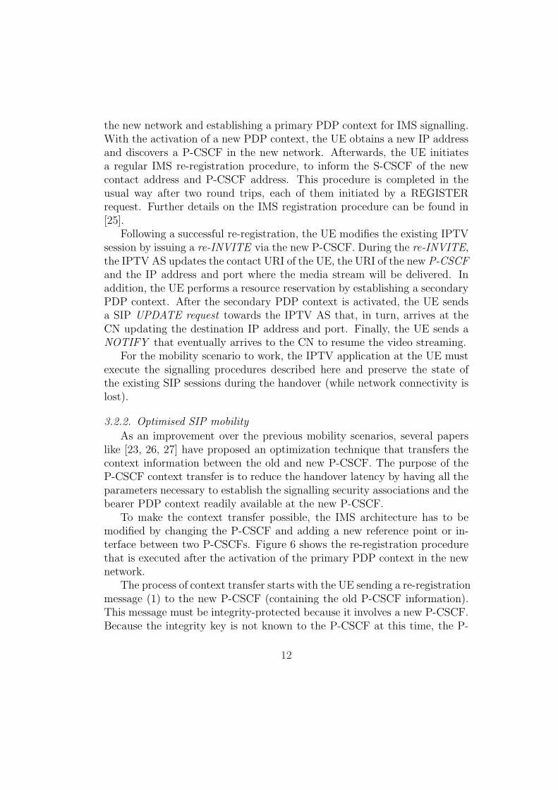
To make the context transfer possible, the IMS architecture has to bemodified by changing the P-CSCF and adding a new reference point or in-terface between two P-CSCFs. Figure 6 shows the re-registration procedurethat is executed after the activation of the primary PDP context in the newnetwork.
The process of context transfer starts with the UE sending a re-registrationmessage (1) to the new P-CSCF (containing the old P-CSCF information).This message must be integrity-protected because it involves a new P-CSCF.Because the integrity key is not known to the P-CSCF at this time, the P-
12
UE P-CSCF new P-CSCF old S-CSCF
New network Old network Home network
(1) Re-registration request
(2) Context transfer request
(3) Context transfer response
(4) Re-registration request
(5) Final response
(6) Final response
Figure 6: Re-registration with P-CSCF context transfer
CSCF must defer the verification of the message and UE authenticity untilafter the context transfer. After receiving the context transfer request, thenew P-CSCF contacts the old P-CSCF in order to retrieve the UE contextparameters including the encryption keys for the security associations, andthe media parameters and filters of the previous sessions (2-3). If the con-text transfer is successful and the integrity of the re-registration request isverified, the S-CSCF is informed of the UE location change (4-5).
Due to the P-CSCF context transfer, the modification of the IPTV sessionat the UE requires only three message exchanges, an initial re-INVITE sentto the IPTV AS containing an SDP with the new media parameters at theUE-side, a final OK response and an ACK. Following the reception of there-INVITE request, the new P-CSCF will create a new traffic filter with themedia parameters from the transferred context and new UE. At the sametime, the UE establishes a secondary PDP context within the new GPRSaccess network. In parallel, upon receiving the INVITE the IPTV AS willtrigger a session update for the media parameters at the CN side. Finally,a notification to resume the streaming informs the CN that the handoverprocess is completed. Figure 7 summarizes the signalling flow.
3.2.3. Mobile IP and IMS
Mobile IP (MIP) [10, 11] solves the mobility problem by allowing the UEto maintain network layer connectivity while moving to a visited network.With MIP, the mobile UE has two IP addresses, the Home Address (HoA)and the Care-of Address (CoA). In order to maintain communications, themobile UE uses the HoA as a permanent address, making the mobility trans-parent for applications and the correspondent node. In order to deliver theIP packets to the UE, the UE also receives a temporary address, the CoA,which is topologically correct in the visited network. A Home Agent (HA)in the home network, the network where the HoA is topologically correct,
13

Up
da
te
pe
er
se
ssio
nRe
-in
vite
P-CSCF ANUE AN ANP-CSCF S-CSCF IPTV-AS CN
New network Old network Home network
INVITE INVITE INVITE
ACK ACK ACK
Correspondent network
200 OK 200 OK 200 OK
Activate secondary PDP context
Modify secondary PDP context
UE pauses the channel, deletes the old PDP context, moves to the new network, activates a new PDP context
200 OK
UPDATE
UPDATE
200 OK
Re-register and transfer context
UE resumes the channel
Figure 7: Optimised SIP mobility with P-CSCF context transfer
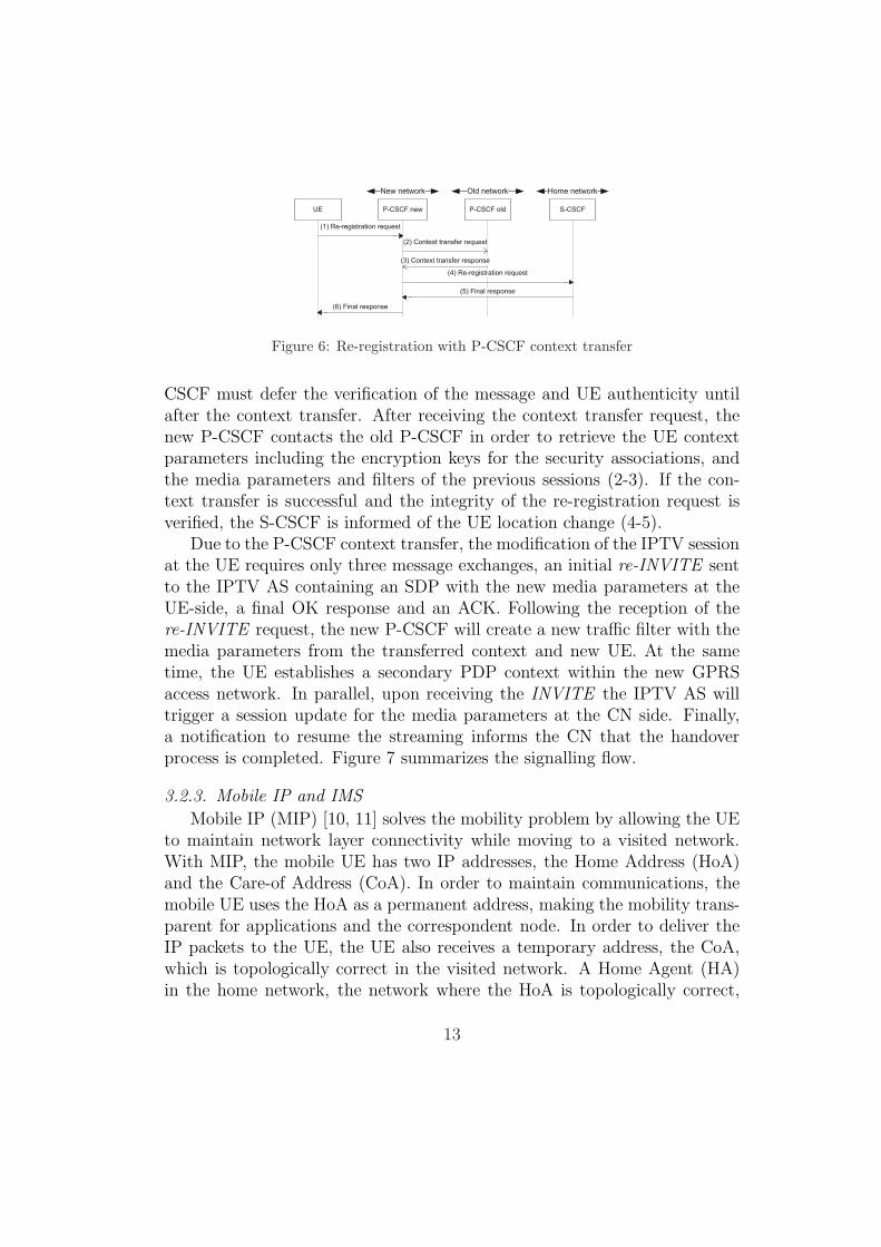
is responsible for sending and receiving the IP datagrams on behalf of themobile node, by using a bidirectional IP in IP tunnel.
Figure 8 summarizes the operation of MIP version 6 in tunnel mode5. Thefirst step is an authenticated binding procedure, through which the mobileUE informs the HA of its CoA. At the end of the binding procedure a MIPtunnel through the HA is established and a communication between the UEand a CN takes place as follows. The outbound IP datagrams (from the UE tothe CN) are tunneled to the HA with the HA Address (HAA) as destination,which in turn will use the topologically correct HoA to forward the packetsto the CN. The inbound IP datagrams, having the HoA as destination andarriving in the home network, are intercepted by the HA and sent throughan IP tunnel to the UE using the CoA.
While MIP offers an attractive solution for seamless transition to mobilescenarios, its integration with the GPRS access technology and with IMSpresents several challenges [23]. The allocation of network resources, includ-ing the provision of QoS, involves the creation of appropriate filters in thenetwork gateways (in the GGSN for GPRS). These filters include the IP ad-
5A major difference between MIPv6 and MIPv4 is that the protocol used to set up theMIP tunnel is different. In addition, in MIPv4, due to the limited number of addressesand for mobility detection purposes, an entity called Foreign Agent (FA) is present in thevisited network. The FA is usually the end of the MIP tunnel and its address can be usedas the CoA for every mobile node within the visited network. Finally, MIPv6 includesan optional route optimization procedure that allows the sending of data traffic directlybetween the CN and the mobile node without going through the HA (not shown in Fig.8).
14
UE HA CN
Visited network Home network Correspondent network
Binding Update
UE roams to a visited
network and is assigned a
CoA
Binding Acknowledge
HA maps CoA to HoA
UE sends a datagram to CN
HoA CNA payload CoA HAA payloadHoA CNA HoA CNA payload
MIP tunnel
CN sends a datagram to UE
CNA HoA payloadHAA CoA payloadCNA HoA
CNA HoA payload
MIP tunnel
Legend
HoA – Home address
CoA – Care-of address
HAA – Home agent address
CNA – Correspondent node address
Figure 8: Mobile IP version 6
dresses of the nodes for which the communication is allowed and they areinstalled during the session establishment according to the Session Descrip-tion Protocol (SDP) [28] body in the SIP messages.
Due to the tunneled communication between the UE and the HA, theuse of MIP cannot be made transparent to the UE and to the IMS network.On the one hand, in MIP the HoA is the permanent address of the mobileUE, and therefore it should be used by the CN and the IMS core. On theother hand, the access network serving the mobile UE requires that resourcereservation and filtering are done using the IP address assigned to the mobilein that access network (i.e. the CoA). As a consequence, using MIP in IMSrequires changes in IMS functional entities to make them MIP aware asproposed in [23].
Nevertheless, the use of MIP could bring major benefits, since with MIPthe mobility of the UE is transparent for CNs and applications as the UE isalways addressed by the HoA. MIP could also bring additional advantages,depending on the network where the P-CSCF is located (home or visited),simplifying the IMS procedures after mobility. The different scenarios willbe studied next, highlighting the mentioned benefits.
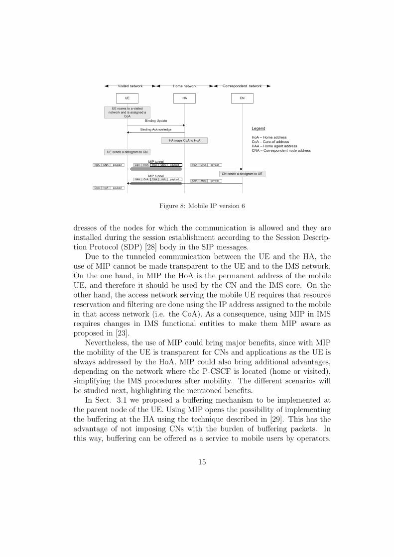
In Sect. 3.1 we proposed a buffering mechanism to be implemented atthe parent node of the UE. Using MIP opens the possibility of implementingthe buffering at the HA using the technique described in [29]. This has theadvantage of not imposing CNs with the burden of buffering packets. Inthis way, buffering can be offered as a service to mobile users by operators.
15

Resum
e
channe
l
Pa
use
channel
Sessio
nm
odific
ation
(sig
na
ling
sen
tth
rough
MIP
tunnel)
HA P-CSCFUE AN AN S-CSCF IPTV-AS CN
Ho
A
New network Home network
Co
A
Media stream (to HoA)
MIPv6: Binding Update
MIPv6: Binding Acknowledge
Ho
A
Media stream (to HoA)
Old network
Delete old PDP contexts
Activate primary PDP context
Corresp.
network
Media stream and buffered data (via MIP tunnel)
INVITE INVITE INVITE
183 Sess. prog.183 Sess. prog.183 Session progress
PRACK PRACK PRACK
200 OK200 OK200 OK
200 OK200 OK200 OK
ACK ACK ACK
200 OK 200 OK 200 OK
UPDATE UPDATE UPDATEActivate secondary PDP context
MIPv6: Binding Update Transient (pause)
MIPv6: Binding Acknowledge Transient (pause)
MIPv6: Binding Update Transient (resume)
MIPv6: Binding Acknowledge Transient (resume)
Stop buffering
Media stream (to HoA)
Start bufferingMove to new network
Figure 9: Handover procedure with MIP and P-CSCF in the home network
Buffering in the HA, as described, can be offered only if the MN does notuse the Route Optimization feature of MIPv6, if the MN is using routeoptimization, then buffering can be done in the CN as described in previoussection. In the rest of the section, we assume that route optimization is notactivated.
Figure 9 illustrates a mobility scenario involving MIP and where the P-CSCF is located in the home network. The IMS signalling is tunneled withMIP via the HA and the UE does not have to re-register to IMS when movingto a visited network. A number of modifications are necessary in the UE, theIMS core and session description information in order to support this MIPscenario. When the UE is in the visited network, all IP datagrams are sentand received using the HoA as if the UE was located in the home network.
16
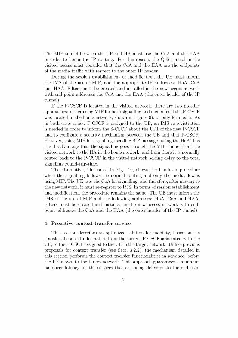
The MIP tunnel between the UE and HA must use the CoA and the HAAin order to honor the IP routing. For this reason, the QoS control in thevisited access must consider that the CoA and the HAA are the endpointsof the media traffic with respect to the outer IP header.
During the session establishment or modification, the UE must informthe IMS of the use of MIP, and the appropriate IP addresses: HoA, CoAand HAA. Filters must be created and installed in the new access networkwith end-point addresses the CoA and the HAA (the outer header of the IPtunnel).
If the P-CSCF is located in the visited network, there are two possibleapproaches: either using MIP for both signalling and media (as if the P-CSCFwas located in the home network, shown in Figure 9), or only for media. Asin both cases a new P-CSCF is assigned to the UE, an IMS re-registrationis needed in order to inform the S-CSCF about the URI of the new P-CSCFand to configure a security mechanism between the UE and that P-CSCF.However, using MIP for signalling (sending SIP messages using the HoA) hasthe disadvantage that the signalling goes through the MIP tunnel from thevisited network to the HA in the home network, and from there it is normallyrouted back to the P-CSCF in the visited network adding delay to the totalsignalling round-trip-time.
The alternative, illustrated in Fig. 10, shows the handover procedurewhen the signalling follows the normal routing and only the media flow isusing MIP. The UE uses the CoA for signalling, and therefore, after moving tothe new network, it must re-register to IMS. In terms of session establishmentand modification, the procedure remains the same. The UE must inform theIMS of the use of MIP and the following addresses: HoA, CoA and HAA.Filters must be created and installed in the new access network with end-point addresses the CoA and the HAA (the outer header of the IP tunnel).
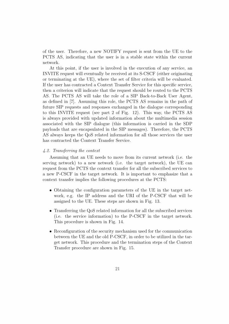
4. Proactive context transfer service
This section describes an optimized solution for mobility, based on thetransfer of context information from the current P-CSCF associated with theUE, to the P-CSCF assigned to the UE in the target network. Unlike previousproposals for context transfer (see Sect. 3.2.2), the mechanism detailed inthis section performs the context transfer functionalities in advance, beforethe UE moves to the target network. This approach guarantees a minimumhandover latency for the services that are being delivered to the end user.
17

Sessio
nm
odific
ation
(sig
nalin
gsentth
rough
MIP
tunnel)
HAP-CSCFUE AN AN S-CSCF IPTV-AS CN
New network Home network
Co
AH
oA
Old network
Activate secondary PDP context
Re-registration of IMS identity to CoA and new P-CSCF
Corresp.
network
INVITE INVITE INVITE
183 Sess. prog.183 Sess. prog.183 Session progress
PRACK PRACK PRACK
200 OK200 OK200 OK
200 OK200 OK200 OK
200 OK 200 OK 200 OK
UPDATE UPDATE UPDATE
ACK ACK ACK
UE pauses the channel using MIPv6, deletes the old PDP context, moves to the new network, activates a new PDP context and binds to the HA
The HA starts buffering the stream on the behalf of the UE
UE resumes the channel using MIPv6
The HA stops buffering the stream and sends the buffered data to the UE
Figure 10: Handover procedure with MIP and P-CSCF in a visited network
The mechanism utilizes the IMS infrastructure, as defined by 3GPP, andIEEE 802.21 methods in order to configure the security mechanism that willbe used for the communication between the UE and the new P-CSCF, and totransfer the QoS related information to the new P-CSCF for those servicesthat are being accessed by the end user. Figure 11 depicts the architectureof the proposed solution.
The proposed procedure uses the handover enabling mechanisms of IEEE802.21 [24]. IEEE 802.21 is a recent standard that aims at enhancing theuser experience, by including mechanisms to improve the performance of han-dovers between heterogeneous technologies. This is done by introducing aset of primitives, which enable the communication between different networkentities and the UE. We have chosen IEEE 802.21 to provide the communi-cation mechanisms that enables the exchange of information required for thecontext transfer.
The Proactive Context Transfer Service (PCTS) described in this sec-tion will be supported by means of a SIP Application Server (AS). Any usersubscribed to this service will be served by a PCTS AS located in its homenetwork, which will be in charge of managing the mobility of the user andinitiating the context transfer to a new P-CSCF located in the target net-work. The user subscription to the PCTS presents a per-service granularity,
18
PoSPoSPoS
CTS AS
MIHF
P-CSCF
IMS core
MIH_SAP
UE
SIP
MIHF
MIH_SAP
Gm
CTS AS
MIHF
P-CSCF
IMS core
MIH_SAP
UE
SIP
MIHF
MIH_SAP
Gm
Moving
RPa RPa
CTS AS
MIHF
S-CSCF
IMS core
MIH_SAP
ISC
HSSMw
Mw
MIISCx
New network Old network Home network Other networkRPb
802.21
802.21
802.21(MIH_NET_SAP)
802.21(MIH_NET_SAP)
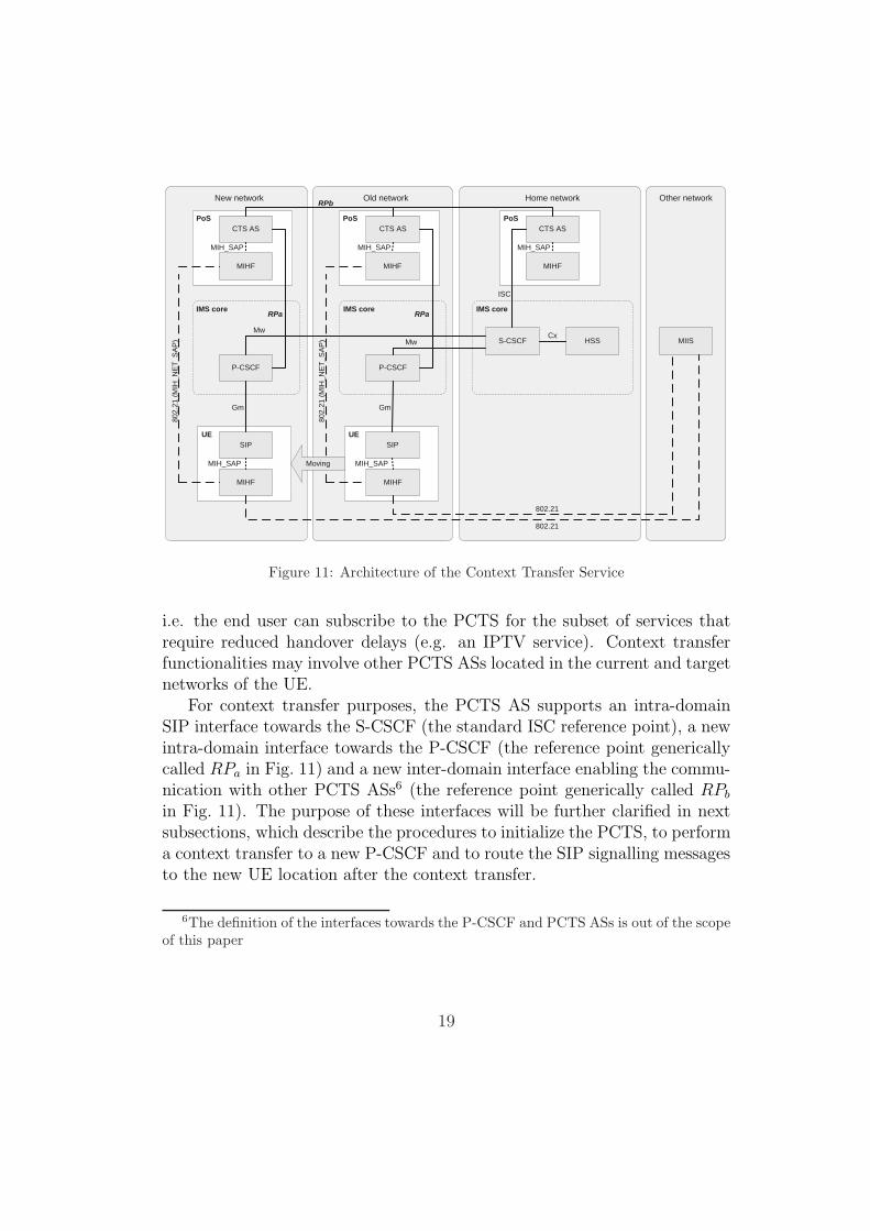
Figure 11: Architecture of the Context Transfer Service
i.e. the end user can subscribe to the PCTS for the subset of services thatrequire reduced handover delays (e.g. an IPTV service). Context transferfunctionalities may involve other PCTS ASs located in the current and targetnetworks of the UE.
For context transfer purposes, the PCTS AS supports an intra-domainSIP interface towards the S-CSCF (the standard ISC reference point), a newintra-domain interface towards the P-CSCF (the reference point genericallycalled RPa in Fig. 11) and a new inter-domain interface enabling the commu-nication with other PCTS ASs6 (the reference point generically called RPb
in Fig. 11). The purpose of these interfaces will be further clarified in nextsubsections, which describe the procedures to initialize the PCTS, to performa context transfer to a new P-CSCF and to route the SIP signalling messagesto the new UE location after the context transfer.
6The definition of the interfaces towards the P-CSCF and PCTS ASs is out of the scopeof this paper
19
UE P-CSCF S-CSCF PCTS AS
Part 1
IMS registration
SUBSCRIBE
Evaluation of initial Filter Criteria
SUBSCRIBE
200 OK200 OK
NOTIFY NOTIFY
200 OK200 OK
NOTIFYNOTIFY
200 OK200 OK
Part 2
From remote
party
INVITE
Evaluation of initial Filter Criteria
INVITE
Store session description
INVITEINVITE
183 Session in Progress 183 Session in Progress
Update session description
183 Session in Progress
183 Session in ProgressTo remote
party
Visited network Home network
Figure 12: Initializing the Context Transfer Service
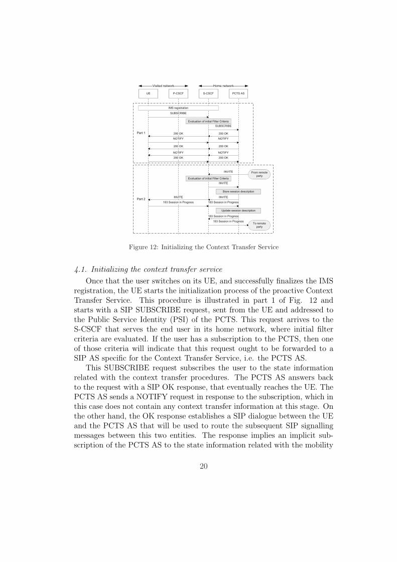
4.1. Initializing the context transfer service
Once that the user switches on its UE, and successfully finalizes the IMSregistration, the UE starts the initialization process of the proactive ContextTransfer Service. This procedure is illustrated in part 1 of Fig. 12 andstarts with a SIP SUBSCRIBE request, sent from the UE and addressed tothe Public Service Identity (PSI) of the PCTS. This request arrives to theS-CSCF that serves the end user in its home network, where initial filtercriteria are evaluated. If the user has a subscription to the PCTS, then oneof those criteria will indicate that this request ought to be forwarded to aSIP AS specific for the Context Transfer Service, i.e. the PCTS AS.
This SUBSCRIBE request subscribes the user to the state informationrelated with the context transfer procedures. The PCTS AS answers backto the request with a SIP OK response, that eventually reaches the UE. ThePCTS AS sends a NOTIFY request in response to the subscription, which inthis case does not contain any context transfer information at this stage. Onthe other hand, the OK response establishes a SIP dialogue between the UEand the PCTS AS that will be used to route the subsequent SIP signallingmessages between this two entities. The response implies an implicit sub-scription of the PCTS AS to the state information related with the mobility
20
of the user. Therefore, a new NOTIFY request is sent from the UE to thePCTS AS, indicating that the user is in a stable state within the currentnetwork.
At this point, if the user is involved in the execution of any service, anINVITE request will eventually be received at its S-CSCF (either originatingor terminating at the UE), where the set of filter criteria will be evaluated.If the user has contracted a Context Transfer Service for this specific service,then a criterion will indicate that the request should be routed to the PCTSAS. The PCTS AS will take the role of a SIP Back-to-Back User Agent,as defined in [7]. Assuming this role, the PCTS AS remains in the path offuture SIP requests and responses exchanged in the dialogue correspondingto this INVITE request (see part 2 of Fig. 12). This way, the PCTS ASis always provided with updated information about the multimedia sessionassociated with the SIP dialogue (this information is carried in the SDPpayloads that are encapsulated in the SIP messages). Therefore, the PCTSAS always keeps the QoS related information for all those services the userhas contracted the Context Transfer Service.
4.2. Transferring the context
Assuming that an UE needs to move from its current network (i.e. theserving network) to a new network (i.e. the target network), the UE canrequest from the PCTS the context transfer for all the subscribed services toa new P-CSCF in the target network. It is important to emphasize that acontext transfer implies the following procedures at the PCTS:
• Obtaining the configuration parameters of the UE in the target net-work, e.g. the IP address and the URI of the P-CSCF that will beassigned to the UE. These steps are shown in Fig. 13.
• Transferring the QoS related information for all the subscribed services(i.e. the service information) to the P-CSCF in the target network.This procedure is shown in Fig. 14.
• Reconfiguration of the security mechanism used for the communicationbetween the UE and the old P-CSCF, in order to be utilized in the tar-get network. This procedure and the termination steps of the ContextTransfer procedure are shown in Fig. 15.
21

PoSPoSUE
(2)
(1)
SIP MIHF PCTS AS MIHF
New network
P-CSCF PCTS AS MIHF
Old network
MIIS
Other
network
MIH_Get_Information.request
MIH_Get_Information.request
MIH_Get_Information.response
MIH_Get_Information.response
MIH_MN_HO_Candidate_Query.request
MIH_MN_HO_Candidate_Query.request
MIH_MN_HO_Candidate_Query.indication
MIH_N2N_HO_Query_Resources.request
MIH_N2N_HO_Query_Resources.request
MIH_N2N_HO_Query_Resources.indication
MIH_N2N_HO_Query_Resources.response
MIH_N2N_HO_Query_Resources.response
MIH_N2N_HO_Query_Resources.confirm
MIH_MN_HO_Candidate_Query.response
MIH_MN_HO_Candidate_Query.response
MIH_MN_HO_Candidate_Query.confirm
PCTS AS returns IP configuration
mechanisms and addresses
UE obtains P-CSCF URI
and network identifier
Figure 13: PCTS Phase 1 - Gathering information about the candidate networks
22
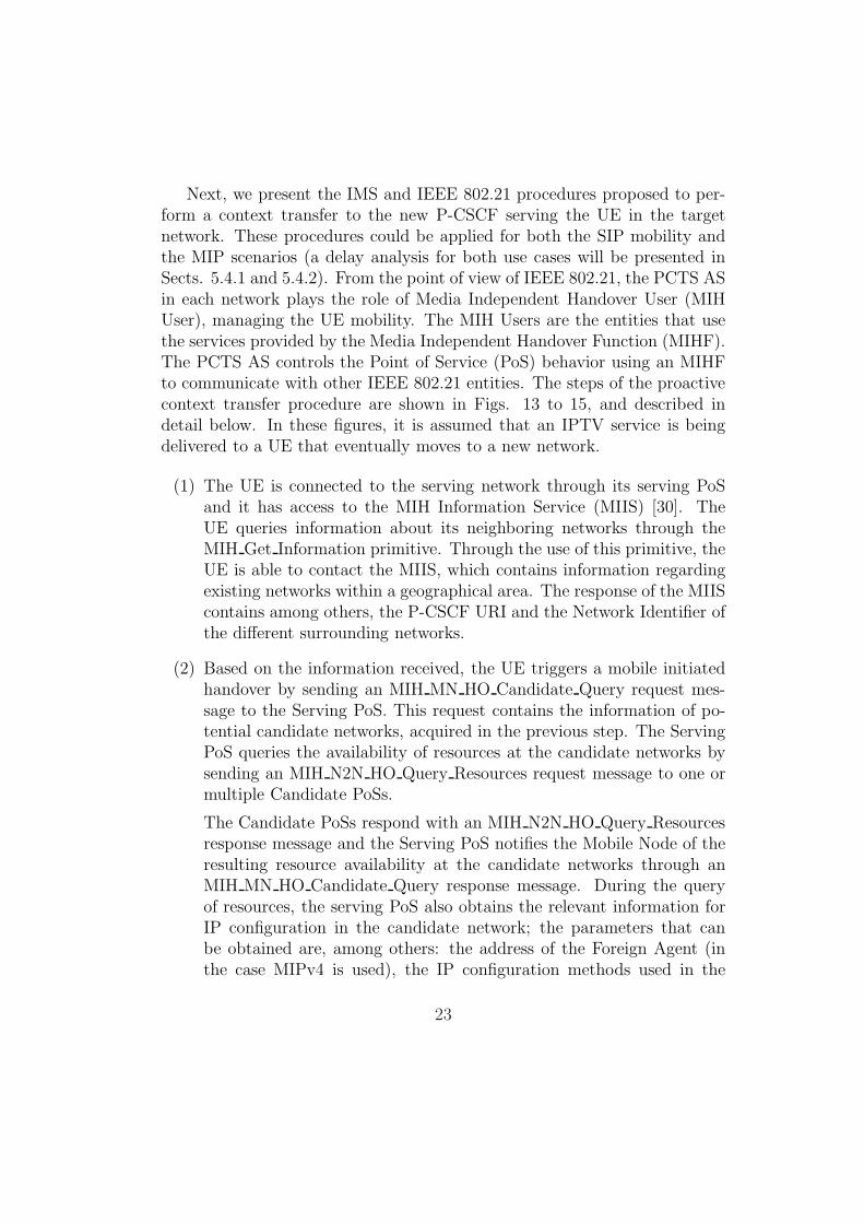
Next, we present the IMS and IEEE 802.21 procedures proposed to per-form a context transfer to the new P-CSCF serving the UE in the targetnetwork. These procedures could be applied for both the SIP mobility andthe MIP scenarios (a delay analysis for both use cases will be presented inSects. 5.4.1 and 5.4.2). From the point of view of IEEE 802.21, the PCTS ASin each network plays the role of Media Independent Handover User (MIHUser), managing the UE mobility. The MIH Users are the entities that usethe services provided by the Media Independent Handover Function (MIHF).The PCTS AS controls the Point of Service (PoS) behavior using an MIHFto communicate with other IEEE 802.21 entities. The steps of the proactivecontext transfer procedure are shown in Figs. 13 to 15, and described indetail below. In these figures, it is assumed that an IPTV service is beingdelivered to a UE that eventually moves to a new network.
(1) The UE is connected to the serving network through its serving PoSand it has access to the MIH Information Service (MIIS) [30]. TheUE queries information about its neighboring networks through theMIH Get Information primitive. Through the use of this primitive, theUE is able to contact the MIIS, which contains information regardingexisting networks within a geographical area. The response of the MIIScontains among others, the P-CSCF URI and the Network Identifier ofthe different surrounding networks.
(2) Based on the information received, the UE triggers a mobile initiatedhandover by sending an MIH MN HO Candidate Query request mes-sage to the Serving PoS. This request contains the information of po-tential candidate networks, acquired in the previous step. The ServingPoS queries the availability of resources at the candidate networks bysending an MIH N2N HO Query Resources request message to one ormultiple Candidate PoSs.
The Candidate PoSs respond with an MIH N2N HO Query Resourcesresponse message and the Serving PoS notifies the Mobile Node of theresulting resource availability at the candidate networks through anMIH MN HO Candidate Query response message. During the queryof resources, the serving PoS also obtains the relevant information forIP configuration in the candidate network; the parameters that canbe obtained are, among others: the address of the Foreign Agent (inthe case MIPv4 is used), the IP configuration methods used in the
23
candidate network, the candidate network DHCP server address (ifrequired) and the IPv6 address of the Access Router.
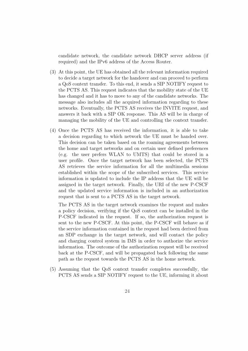
(3) At this point, the UE has obtained all the relevant information requiredto decide a target network for the handover and can proceed to performa QoS context transfer. To this end, it sends a SIP NOTIFY request tothe PCTS AS. This request indicates that the mobility state of the UEhas changed and it has to move to any of the candidate networks. Themessage also includes all the acquired information regarding to thesenetworks. Eventually, the PCTS AS receives the INVITE request, andanswers it back with a SIP OK response. This AS will be in charge ofmanaging the mobility of the UE and controlling the context transfer.
(4) Once the PCTS AS has received the information, it is able to takea decision regarding to which network the UE must be handed over.This decision can be taken based on the roaming agreements betweenthe home and target networks and on certain user defined preferences(e.g. the user prefers WLAN to UMTS) that could be stored in auser profile. Once the target network has been selected, the PCTSAS retrieves the service information for all the multimedia sessionsestablished within the scope of the subscribed services. This serviceinformation is updated to include the IP address that the UE will beassigned in the target network. Finally, the URI of the new P-CSCFand the updated service information is included in an authorizationrequest that is sent to a PCTS AS in the target network.
The PCTS AS in the target network examines the request and makesa policy decision, verifying if the QoS context can be installed in theP-CSCF indicated in the request. If so, the authorization request issent to the new P-CSCF. At this point, the P-CSCF will behave as ifthe service information contained in the request had been derived froman SDP exchange in the target network, and will contact the policyand charging control system in IMS in order to authorize the serviceinformation. The outcome of the authorization request will be receivedback at the P-CSCF, and will be propagated back following the samepath as the request towards the PCTS AS in the home network.
(5) Assuming that the QoS context transfer completes successfully, thePCTS AS sends a SIP NOTIFY request to the UE, informing it about
24

UE
(5)
(4)
(3)
SIP P-CSCF PCTS AS
New network
P-CSCF
Old network
PCTS ASS-CSCF
Home network
Definition of new service
information
Auth. request [service info]
Policy decision
Auth. request [service info]
Visited PCRF is
contacted to authorize
service information
Auth. response
Auth. response
NOTIFY [list of candidate networks and associated parameters] NOTIFY
200 OK200 OK
Selection of a target
network based on user
preferences
200 OK
NOTIFY [target network]NOTIFY
200 OK
NOTIFY
NOTIFY
200 OK 200 OK
Figure 14: PCTS Phase 2 - Network selection procedure
the changes in its connection status, i.e. the target network that hasbeen selected, the IP address and the URI of the P-CSCF that havebeen assigned to the UE in this network and an indication that theQoS transfer has been transferred successfully.
In order to improve the performance of the handover, a new parameterhas been introduced in the MIH N2N HO Commit primitive. This new pa-rameter is able to carry the IPsec parameters of a connection, being used totransfer the security context from the Serving PoS to the Target PoS in sucha way that the UE does not need to re-authenticate itself during the han-dover. The IPsec parameters transported in the primitive are the cipheringalgorithm used by IPsec, the SPIs (Security Parameter Index) defining thesecurity association, the ports used for the secure communication and theciphering and integrity keys. This extension to the IEEE 802.21 standardis required to improve the performance of the handover, but the rest of theprocedure follows the standard mechanisms.
(6) Upon receiving this indication from the PCTS AS, the UE notifies theinformation about the selected target network to the Serving PoS, by
25

PoSPoSUE
(8)
SIP MIHF P-CSCF PCTS AS MIHF
New network
P-CSCF PCTS AS MIHF
Old network
PCTS ASS-CSCF
Home Network
MIH_MN_HO_Commit.request MIH_MN_HO_Commit.request
MIH_MN_HO_Commit.indication
MIH_N2N_HO_Commit.request
MIH_N2N_HO_Commit.requestMIH_N2N_HO_Commit.indication
MIH_N2N_HO_Commit.response MIH_N2N_HO_Commit.response
MIH_N2N_HO_Commit.confirm
MIH_MN_HO_Commit.response
MIH_MN_HO_Commit.responseMIH_MN_HO_Commit.confirm
PCTS AS installs UE IPsec
parameters and retrieves P-CSCF
IPsec parameters from new P-CSCF
Move to new network
Delete old PDP contexts
Activate PDP contexts
Update configuration
Contact the source to update
the destination address and
to resume the media stream
MIH_N2N_HO_Complete.response
MIH_N2N_HO_Complete.confirm
MIH_MN_HO_Complete.response
MIH_MN_HO_Complete.responseMIH_MN_HO_Complete.confirm
PCTS AS retrieves UE IPsec
parameters from current P-CSCF
PCTS AS returns IPsec
parameters from new P-CSCF
Pause the media stream
(6)
NOTIFY NOTIFY NOTIFY
200 OK200 OK
(7)
Media stream (from CN)
MIH_MN_HO_Complete.request MIH_MN_HO_Complete.request
MIH_MN_HO_Complete.indication
MIH_N2N_HO_Complete.request
MIH_N2N_HO_Complete.request
MIH_MN_HO_Complete.indication
MIH_N2N_HO_Complete.response
200 OK
Figure 15: PCTS Phase 3 - Handover completion
26
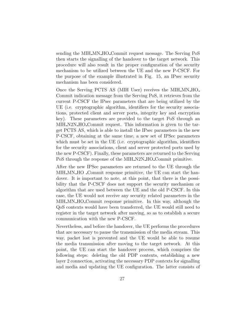
sending the MIH MN HO Commit request message. The Serving PoSthen starts the signalling of the handover to the target network. Thisprocedure will also result in the proper configuration of the securitymechanism to be utilized between the UE and the new P-CSCF. Forthe purpose of the example illustrated in Fig. 15, an IPsec securitymechanism has been considered.
Once the Serving PCTS AS (MIH User) receives the MIH MN HOCommit indication message from the Serving PoS, it retrieves from thecurrent P-CSCF the IPsec parameters that are being utilized by theUE (i.e. cryptographic algorithm, identifiers for the security associa-tions, protected client and server ports, integrity key and encryptionkey). These parameters are provided to the target PoS through anMIH N2N HO Commit request. This information is given to the tar-get PCTS AS, which is able to install the IPsec parameters in the newP-CSCF, obtaining at the same time, a new set of IPSec parameterswhich must be set in the UE (i.e. cryptographic algorithm, identifiersfor the security associations, client and server protected ports used bythe new P-CSCF). Finally, these parameters are returned to the ServingPoS through the response of the MIH N2N HO Commit primitive.
After the new IPSec parameters are returned to the UE through theMIH MN HO Commit response primitive, the UE can start the han-dover. It is important to note, at this point, that there is the possi-bility that the P-CSCF does not support the security mechanism oralgorithm that are used between the UE and the old P-CSCF. In thiscase, the UE would not receive any security related parameters in theMIH MN HO Commit response primitive. In this way, although theQoS contexts would have been transferred, the UE would still need toregister in the target network after moving, so as to establish a securecommunication with the new P-CSCF.
Nevertheless, and before the handover, the UE performs the proceduresthat are necessary to pause the transmission of the media stream. Thisway, packet lost is prevented and the UE would be able to resumethe media transmission after moving to the target network. At thispoint, the UE can start the handover process, which comprises thefollowing steps: deleting the old PDP contexts, establishing a newlayer 2 connection, activating the necessary PDP contexts for signallingand media and updating the UE configuration. The latter consists of
27

updating the IPsec related information and the URI of the P-CSCFfor future SIP requests. Next, the UE informs the source of the mediastream about the new destination address, and the media is resumed.
The procedure to pause and resume a video stream is different for SIPmobility and MIP use cases. In the former, as described in Sect. 3.2.1,the procedure is based on SIP signalling and, in the latter, as describedin Sect. 3.2.3, the procedure is based on MIP signalling.
(7) In order to finalize the handover procedure, the UE sends an MIH MNHO Complete request message to the target PoS. The target PoS sendsan MIH N2N HO Complete request message to the previous ServingPoS to release resources, which were allocated to the UE. After identi-fying that the resources are successfully released, the target PoS sendsan MIH MN HO Complete response message to the UE.
(8) At this point, the UE notifies to the Home Network PCTS AS thefinalization of the handover and its new location. This message endsthe Context Transfer procedure. From this moment on, the PCTS ASwill route subsequent SIP requests within the scope of the subscribedservices to the new UE contact address (the new contact address simplyupdates the IP address), through the new P-CSCF.
It is important to point out that, at this stage, the S-CSCF in the userhome network has not been yet notified about the new contact address of theUE and the URI of the new P-CSCF that it has been assigned. Therefore,new INVITE requests for non-subscribed services, addressed to the publicURI of the end user, would not be delivered from the S-CSCF to its UE. Toaddress this issue, the UE needs to re-register with the S-CSCF. However,this registration process is not necessary from the perspective of the servicesthat are already subscribed in the PCTS (i.e. the PCTS AS will be in chargeof routing the SIP signalling corresponding to these services towards the UE),and consequently it can be performed after the context transfer procedure.
5. Delay analysis for mobile streaming in IMS
After presenting the previous proposals to perform a handover in IMSin Sect. 3, and our proposal in Sect. 4, this section presents an analyticalstudy to obtain the mobility delay for each of them, in order to compare all
28

Parameter Value (ms)Tact,PDPp 2340Tact,PDPs 1940Tregistration 1280Tproc,CSCF 25
Table 1: Delay values used for the analysis
mechanisms in a scenario where the UE moves to a UMTS network. We areinterested in analyzing the duration that the video is paused in the CN (orthe HA in the MIP case), during the UE handover procedure, because thisis the time during which the CN (HA) has to buffer the video packets onbehalf of the UE. We denote this delay by Tbuff .
The final results are presented in two ways: a general equation and anapproximate value, in order to compare all mobility mechanisms. Some nu-merical input values for our analysis were extracted from [31], and are sum-marized in Table 1. These values are defined as follows:
• Tact,PDPp is the time necessary to activate a primary PDP context.
• Tact,PDPs is the time necessary to activate a secondary PDP context.
• Tregistration covers all signalling to register a terminal in the IMS net-work.
• Tproc,CSCF is the time a SIP message needs to traverse a CSCF device(i.e P-CSCF, S-CSCF or I-CSCF).
The time to attach a mobile node to a UMTS network (Tattach) is not in-cluded in that work. Therefore, we experimentally evaluated realistic valuesof Tattach via simulation with the OPNET tool7. In order to do so, a networkscenario for UMTS was used (the large UMTS scenario included in OPNETv15) comprising 58 UE, which arrive to the network at random times. Us-ing this scenario, we performed 100 simulations and, for each of them, weobtained the average value of the time required for a UE to attach to the
7OPNET University Program,http://www.opnet.com/services/university/
29
UMTS network. The worst case of these average values was then used asTattach in the following analysis, resulting in Tattach = 1390 ms.
Another important value is the time necessary to delete a PDP context(both a primary and a secondary). In our proposal, we assume that theterminal just sends the request to delete all its PDP contexts and it leavesimmediately the old access network; hence Tdel,PDPp = Tdel,PDPs = 0 (even ifthe terminal does not send this request, all PDP context are removed aftera time-out). The remaining values used in this section are:
• Tsip is the delay for all SIP signalling involved in a given mechanism.This value includes other SIP related delays, as it will be seen in nextsubsections.
• Tsip,pause is the delay for the SIP OK response sent by the CN afterreceiving the NOTIFY request with the pause indication.
• Tre−invite gathers all delay involved in a re-invite message sequence.
• Tsip,resume is the delay for the SIP NOTIFY request sent by the mobilenode to the CN, requesting a resume of the paused video.
• Tmip is the delay introduced by all the MIP signalling.
The delay corresponding to any SIP message may be decomposed in fivecomponents: (1) the delay in the UMTS access network, (2) the processingdelays at the traversed CSCFs, (3) the processing delay at the IPTV AS, (4)the delays within the core transport network and (5) the delay in the CNaccess network.
Regarding the SIP delays in the UMTS access network (1), a partialimplementation of the IPTV service was developed in Java (version 1.5.0),utilizing the JAIN-SIP API8. Using this Java implementation, the real sizeof every SIP signalling message corresponding to the IPTV service was ob-tained. With these sizes, an experiment was designed to measure the averagedelay experienced by each SIP message in a real UMTS access network duringthe period of high load.
For the experiment a testbed was deployed, consisting of a UE connectedto the Internet by means of a real UMTS access. With this infrastructure,
8JAIN SIP Developer Tools, https://jain-sip.dev.java.net/
30
Message Average delay (ms)
INVITE 134.37Session in Progress 133.33PRACK 133.52OKPRACK 121.26UPDATE 136.62OKUPDATE 121.26OKINV ITE 78.04ACK 80.87NOTIFY 207.32OKNOTIFY 78.13
Table 2: UMTS delays for SIP messages
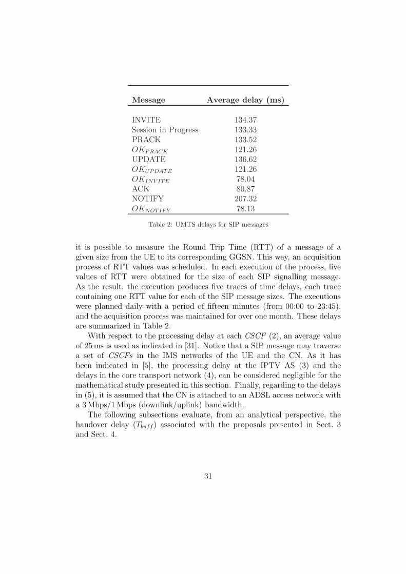
it is possible to measure the Round Trip Time (RTT) of a message of agiven size from the UE to its corresponding GGSN. This way, an acquisitionprocess of RTT values was scheduled. In each execution of the process, fivevalues of RTT were obtained for the size of each SIP signalling message.As the result, the execution produces five traces of time delays, each tracecontaining one RTT value for each of the SIP message sizes. The executionswere planned daily with a period of fifteen minutes (from 00:00 to 23:45),and the acquisition process was maintained for over one month. These delaysare summarized in Table 2.
With respect to the processing delay at each CSCF (2), an average valueof 25 ms is used as indicated in [31]. Notice that a SIP message may traversea set of CSCFs in the IMS networks of the UE and the CN. As it hasbeen indicated in [5], the processing delay at the IPTV AS (3) and thedelays in the core transport network (4), can be considered negligible for themathematical study presented in this section. Finally, regarding to the delaysin (5), it is assumed that the CN is attached to an ADSL access network witha 3 Mbps/1 Mbps (downlink/uplink) bandwidth.
The following subsections evaluate, from an analytical perspective, thehandover delay (Tbuff) associated with the proposals presented in Sect. 3and Sect. 4.
31

5.1. SIP mobility delay
Using Fig. 5 it is easy to obtain the delay:
Tbuff = Tsip + Tattach + Tact,PDPp + Tact,PDPs (2)
In the previous equation, Tsip can be expressed as Tsip = Tsip,pause +Tregistration + Tre−invite + Tsip,resume. To evaluate the previous equation, it isimportant to notice that some messages are processed and/or generated inparallel with other messages. For example, in Fig. 5, after the UE receives theSession in progress, it starts activating the secondary PDP context and, atthe same time, sends the PRACK using the primary PDP context. Other SIPmessages that are transmitted in sequence (both OK responses correspondingto the UPDATE and the INVITE requests, and an ACK with a NOTIFY
request) have to be properly considered.Taking into account the delay in the UMTS access network (as shown in
Table 2), the number of traversed CSCFs and the delay in the ADSL accessnetwork for every SIP message, Tsip can be estimated as Tsip = Tsip,pause +Tregistration + Tre−invite + Tsip,resume = 0.206 s + 1.280 s + 0.753 s + 0.168 s =2.407 s. Finally, Eq. 2 is evaluated as Tbuff = 2.407 s + 5.67 s = 8.077 s.
5.2. SIP context transfer
Let Tsip,standard be the delay introduced by the standard SIP messages inFig. 7 and Tsip,new be the delay introduced by the new messages defined inFig. 6. In this scenario, Eq. 2 is still valid, so the only thing to do is toestimate Tsip = Tsip,standard + Tsip,new = 0.688 s + 0.365 s = 1.053 s. In thiscase, Tbuff = 1.053 s + 5.67 s = 6.723 s.
5.3. Mobile IP
In this case, Tbuff has to be estimated at the HA and not at the CN, aswe are using the ideas proposed in [29] to pause and resume the media.
5.3.1. P-CSCF in the home network
Using Fig. 9 as a reference, we obtain:
Tbuff = Tsip + Tmip + Tattach + Tact,PDPp + Tact,PDPs (3)
In the previous equation Tmip denotes the time necessary to perform abinding update plus the delays of a pause response and a resume requestusing MIP. As a round-trip time (RTT) for the typical packet size of a MIP
32

binding update in UMTS is around 50 ms, Tmip can be estimated as Tmip =Tbinding + Tpause,resp + Tresume,req = 100 ms.
On the other hand, it is important to notice that, in this scenario, itis not necessary to re-register in IMS, because the UE uses the HoA as theregistered IP address, which does not change during the handover. Therefore,in this case Tsip = Tre−invite = 0.744 s. Finally, Tbuff is expressed as Tbuff =0.744 s + 0.1 s + 5.67 s = 6.514 s.
5.3.2. P-CSCF in the visited network
Eq. 3 is still valid in this scenario, and again Tmip = Tbinding +Tpause,resp+Tresume,req, but in this case, as a MIP tunnel is not used for the SIP signalling,it is not necessary to wait for the binding update acknowledgment so Tbinding =0 and Tmip = 50 ms. In this scenario it is necessary to re-register (the mobileterminal registers the CoA in IMS), hence Tsip = Tregistration + Tre−invite =1.280 s + 0.744 s = 2.024 s and Tbuff = 2.024 s + 0.05 s + 5.67 s = 7.744 s.
5.4. PCTS AS
The mechanism described in Sect. 4 can be used with or without mobileIP: there are two scenarios to analyze the delay.
5.4.1. Delay without MIP
From Fig. 15 it is easy to see that Eq. 2 is still valid. In this case,Tsip = Tsip,pause + Tsip,resume = 0.374 s and Tbuff = 0.374 s + 5.67 s = 6.044 s.
5.4.2. Delay with MIP
Eq. 3 is valid also here, but as it is not necessary to send any SIP message(registration is not necessary in MIP, and pause and resume are done usingMIP packets towards the HA as defined in [29]) then Tsip = 0. For MIPsignalling, and using [29] Tmip = 0.1 s then Tbuff = 0.1 s + 5.67 s = 5.77 s.
5.5. Summary of the delays
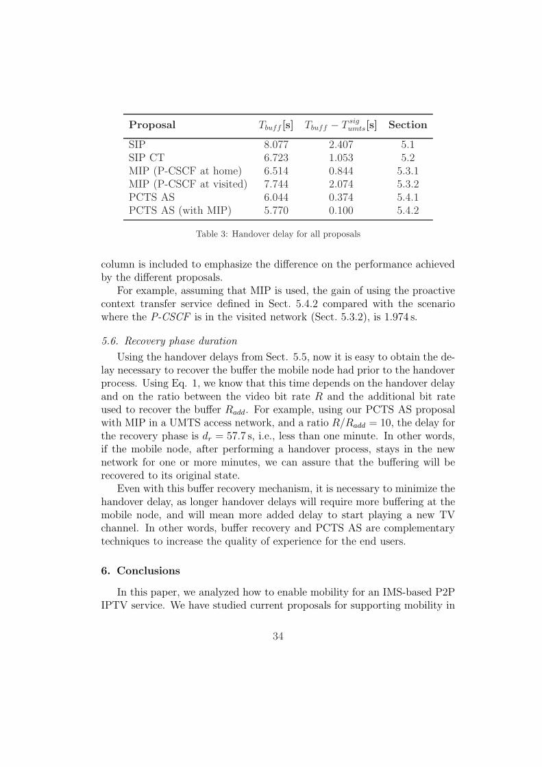
Table 3 summarizes all delays calculated in previous subsections. Thecolumn Tbuff presents the final delay in seconds for each of the consideredscenarios. This value represents the time during which the CN (or HA) hasto buffer the video packets on behalf of the UE. The column Tbuff − T sig
umts
represents the same time as the previous column, but excluding the UMTSsignalling delays, i.e. the time to attach a UMTS node to the network andthe time necessary to activate a primary and a secondary PDP context. This
33
Proposal Tbuff [s] Tbuff − T sigumts[s] Section
SIP 8.077 2.407 5.1SIP CT 6.723 1.053 5.2MIP (P-CSCF at home) 6.514 0.844 5.3.1MIP (P-CSCF at visited) 7.744 2.074 5.3.2PCTS AS 6.044 0.374 5.4.1PCTS AS (with MIP) 5.770 0.100 5.4.2
Table 3: Handover delay for all proposals
column is included to emphasize the difference on the performance achievedby the different proposals.
For example, assuming that MIP is used, the gain of using the proactivecontext transfer service defined in Sect. 5.4.2 compared with the scenariowhere the P-CSCF is in the visited network (Sect. 5.3.2), is 1.974 s.
5.6. Recovery phase duration
Using the handover delays from Sect. 5.5, now it is easy to obtain the de-lay necessary to recover the buffer the mobile node had prior to the handoverprocess. Using Eq. 1, we know that this time depends on the handover delayand on the ratio between the video bit rate R and the additional bit rateused to recover the buffer Radd. For example, using our PCTS AS proposalwith MIP in a UMTS access network, and a ratio R/Radd = 10, the delay forthe recovery phase is dr = 57.7 s, i.e., less than one minute. In other words,if the mobile node, after performing a handover process, stays in the newnetwork for one or more minutes, we can assure that the buffering will berecovered to its original state.
Even with this buffer recovery mechanism, it is necessary to minimize thehandover delay, as longer handover delays will require more buffering at themobile node, and will mean more added delay to start playing a new TVchannel. In other words, buffer recovery and PCTS AS are complementarytechniques to increase the quality of experience for the end users.
6. Conclusions
In this paper, we analyzed how to enable mobility for an IMS-based P2PIPTV service. We have studied current proposals for supporting mobility in
34
IMS-enabled networks in the particular case of a P2P IPTV service. Han-dovers involving changes of the IP address in IMS-based networks requirecomplex protocol interaction that can lead to long handover delays. To avoidlong bursts of packet losses in this paper we propose two novel techniques: (1)a buffering mechanism and (2) a Proactive Context Transfer Service (PCTS).
The purpose of the PCTS is to minimize the service re-establishmentdelay during inter-network handovers. The main idea is to use the existingMedia Independent Handover technology (IEEE 802.21) in order to take aproactive approach in regards to detecting the state information (such as userequipment and proxy addresses) in the new network, applying the necessaryQoS policies and updating the location at the IPTV application server andat the correspondent node.
To validate the benefits of our proposal, we compared the obtained servicesuspension time (or buffering time, i.e. the duration of time the IPTV contenthas to be buffered at the correspondent node or an intermediate equipment)with three other existing solutions. Our results demonstrate that using theContext Transfer Service results in a significant improvement. This has thebenefit of requiring smaller buffer sizes at peer user equipment, and reducingthe overall play-back delay.
Acknowledgements
This article has been partially granted by the Spanish MEC throughthe CONPARTE project (TEC2007-67966-C03-03/TCM) and by the MadridCommunity through the MEDIANET project (S-2009/TIC-1468).
References
[1] International Telecommunications Union, IPTV Architecture, FGIPTV-DOC-0181, draft (2007).
[2] ETSI-TISPAN, Telecommunications and Internet converged Servicesand Protocols for Advanced Networking (TISPAN); IPTV Architecture;IPTV functions supported by the IMS subsystem IPTV IMS-based, In-ternet (February 2008).
[3] B. Quinn, K. Almeroth, IP Multicast Applications: Challenges and So-lutions, RFC 3170 (Informational) (Sep. 2001).URL http://www.ietf.org/rfc/rfc3170.txt
35
[4] A. Sentinelli, G. Marfia, M. Gerla, S. Tewari, L. Kleinrock, Will IPTVride the peer-to-peer stream?, IEEE Communications Magazine 45 (6)(2007) 86–92.
[5] A. Bikfalvi, J. Garcıa-Reinoso, I. Vidal, F. Valera, A peer-to-peer IPTVservice architecture for the IP multimedia subsystem, InternationalJournal of Communication Systems.URL http://dx.doi.org/10.1002/dac.1063
[6] 3GPP, IP Multimedia Subsystem (IMS); Stage 2, TS 23.228, 3rd Gen-eration Partnership Project (3GPP) (Sep. 2008).URL http://www.3gpp.org/ftp/Specs/html-info/23228.htm
[7] J. Rosenberg, H. Schulzrinne, G. Camarillo, A. Johnston, J. Peterson,R. Sparks, M. Handley, E. Schooler, SIP: Session Initiation Protocol,RFC 3261 (Proposed Standard), updated by RFCs 3265, 3853, 4320(Jun. 2002).
[8] P. Calhoun, J. Loughney, E. Guttman, G. Zorn, J. Arkko, DiameterBase Protocol, RFC 3588 (Proposed Standard) (Sep. 2003).URL http://www.ietf.org/rfc/rfc3588.txt
[9] G. Cunningham, P. Perry, J. Murphy, L. Murphy, Seamless handover ofiptv streams in a wireless lan network, Broadcasting, IEEE Transactionson 55 (4) (2009) 796–801. doi:10.1109/TBC.2009.2030466.
[10] C. Perkins, IP Mobility Support for IPv4, RFC 3220 (Proposed Stan-dard), obsoleted by RFC 3344 (Jan. 2002).URL http://www.ietf.org/rfc/rfc3220.txt
[11] D. Johnson, C. Perkins, J. Arkko, Mobility Support in IPv6, RFC 3775(Proposed Standard) (Jun. 2004).URL http://www.ietf.org/rfc/rfc3775.txt
[12] R. K. Ed., Mobile IPv6 Fast Handovers, RFC 5568 (2009).URL http://www.ietf.org/rfc/rfc5568.txt
[13] H. Soliman, C. Castelluccia, K. Elmalki, L. Bellier, Hierarchical MobileIPv6 (HMIPv6) Mobility Management, RFC 5380 (2008).URL http://www.ietf.org/rfc/rfc5380.txt
36

[14] V. Devarapalli, R. Wakikawa, A. Petrescu, P. Thubert, Network Mobil-ity (NEMO) Basic Support Protocol, RFC 3963 (Proposed Standard)(Jan. 2005).URL http://www.ietf.org/rfc/rfc3963.txt
[15] C. Vogt, M. Zitterbart, Efficient and scalable, end-to-end mobility sup-port for reactive and proactive handoffs in IPv6, IEEE CommunicationsMagazine 44 (6).
[16] P. Vidales, C. J. Bernardos, I. Soto, D. Cottingham, J. Baliosian,J. Crowcroft, MIPv6 Experimental Evaluation using Overlay Networks,Computer Networks 51 (10).URL http://dx.doi.org/10.1016/j.comnet.2006.12.004
[17] R. Aguiar, S. Sargento, A. Banchs, C. J. Bernardos, M. Caldern, I. Soto,M. Liebsch, T. Melia, P. Pacyna, Scalable QoS-aware Mobility for FutureMobile Operators, IEEE Communications Magazine 44 (6) (2006) 95 –102.
[18] C. J. Bernardos, I. Soto, J. I. Moreno, T. Melia, M. Liebsch, R. Schmitz,Experimental evaluation of a handover optimization solution for multi-media applications in a mobile IPv6 network, European Transactions onTelecommunications 16 (4) (2005) 317 – 328.URL http://dx.doi.org/10.1002/ett.1005
[19] R. Chakravorty, P. Vidales, K. Subramanian, I. Pratt, J. Crowcroft,Performance Issues with Vertical Handovers - Experiences from GPRSCellular and WLAN hot-spots Integration, in: Proc. Second IEEE In-ternational Conference on Pervasive Computing and Communications(PerCom’04), 2004, pp. 155–164.
[20] S. Balasubramaniam, J. Indulska, Vertical handover supporting perva-sive computing in future wireless networks, Computer Communications27 (8) (2004) 708 – 719.
[21] G. Heine, H. Sagkob, GPRS: gateway to third generation mobile net-works, Artech House Publishers, 2003.
[22] T. Chiba, H. Yokota, A. Dutta, D. Chee, H. Schulzrinne, PerformanceAnalysis of Next Generation Mobility Protocols for IMS/MMD Net-
37

works, in: International Wireless Communications and Mobile Comput-ing Conference (IWCMC’08), 2008.
[23] T. Renier, K. Larsen, G. Castro, H. Schwefel, Mid-Session Macro-Mobility in IMS-Based Networks, IEEE Vehicular Technology Magazine2 (1) (2007) 20–27.
[24] Media Independent Handover Services, IEEE Standard for Local andMetropolitan Area Networks, 2008.
[25] 3GPP, Internet Protocol (IP) multimedia call control protocol basedon Session Initiation Protocol (SIP) and Session Description Protocol(SDP); Stage 3, TS 24.229, 3rd Generation Partnership Project (3GPP)(Sep. 2008).URL http://www.3gpp.org/ftp/Specs/html-info/24229.htm
[26] K. Larsen, E. Matthiesen, H. Schwefel, G. Kuhn, Optimized macro mo-bility within the 3GPP IP multimedia subsystem, in: Wireless and Mo-bile Communications, 2006. ICWMC’06. International Conference on,2006, pp. 82–82.
[27] A. Dutta, K. Manousakis, S. Das, F. Lin, T. Chiba, H. Yokota, A. Idoue,H. Schulzrinne, Mobility Testbed for 3GPP2-Based Multimedia DomainNetworks, IEEE Communications Magazine 45 (7) (2007) 118–126.
[28] M. Handley, V. Jacobson, C. Perkins, SDP: Session Description Proto-col, RFC 4566 (Proposed Standard) (Jul. 2006).
[29] F. Xia, B. Sarikaya, B. Patil, Mobile IPv6 Handover Using Home AgentBuffering, Internet Draft (November 2008).
[30] A. De La Oliva, A. Banchs, I. Soto, T. Melia, A. Vidal, An overviewof IEEE 802.21: media-independent handover services, IEEE WirelessCommunications 15 (4) (2008) 96–103.
[31] D. Pesch, M. Pous, G. Foster, Performance evaluation of SIP-based mul-timedia services in UMTS, Computer Networks 49 (3) (2005) 385–403.
38