Embed Size (px)
Citation preview
UNIVERSITÀ DEGLI STUDI DI BOLOGNA
FACOLTÀ DI INGEGNERIA
Dipartimento di Elettronica Informatica e Sistemistica Dottorato in Ingegneria Elettronica, Informatica e delle Telecomunicazioni
Support Infrastructures for Multimedia Services with
Guaranteed Continuity and QoS Settore Disciplinare: ING-INF05
Ciclo XIX
Candidato:
Luca Foschini
Relatori:
Chiar.mo Prof. Ing. Maurelio Boari
Chiar.mo Prof. Ing. Antonio Corradi
Coordinatore:
Chiar.mo Prof. Ing. Paolo Bassi
Anno Accademico 2005-2006

ii
UNIVERSITÀ DEGLI STUDI DI BOLOGNA
FACOLTÀ DI INGEGNERIA
Dipartimento di Elettronica Informatica e Sistemistica Dottorato in Ingegneria Elettronica, Informatica e delle Telecomunicazioni
Data: Marzo 2007
Relatori:
Correlatori:
Coordinatore:
Chiar.mo Prof. Ing. Maurelio Boari
Chiar.mo Prof. Ing. Antonio Corradi
Chiar.mo Prof. Ing. Paolo Bellavista
Chiar.ma Prof. Ing. Rebecca Montanari
Chiar.mo Prof. Ing. Paolo Bassi
i

ii
To my parents
To Carlotta

iii
© Copyright 2007
by
Luca Foschini
All Rights Reserved
iv
CONTENTS
CONTENTS ..................................................................................................................... iv
LIST OF TABLES.......................................................................................................... viii
LIST OF FIGURES .......................................................................................................... ix
ACKNOWLEDGMENT .................................................................................................. xi
ABSTRACT .................................................................................................................... xii
1. Introduction.................................................................................................................. 1
2. Mobile Multimedia Provisioning in the WI: Background........................................... 6
2.1 Wireless Internet (WI) and Mobile Devices ...................................................... 6
2.1.1 WI Network Infrastructure..................................................................... 6
2.1.2 Mobile Devices: Enhanced Wireless Capabilities and Challenges...... 11
2.1.3 Wireless Communication Impairments................................................ 12
2.2 Multimedia Services ........................................................................................ 14
2.2.1 Multimedia Provisioning and QoS Management................................. 14
2.2.2 Mobile Multimedia with Guaranteed QoS in the WI........................... 17
2.2.3 QoS Specification and Main Multimedia Application Types .............. 19
2.3 Handoff Management....................................................................................... 22
2.3.1 Handoff Terminology .......................................................................... 22
2.3.2 Handoff Impairments ........................................................................... 25
2.3.3 Mobile Multimedia Handoff Management: Challenges ...................... 26
2.4 Chapter Conclusions ........................................................................................ 28
3. A Full Context-Aware Middleware Architecture for Handoff Management ............ 29
3.1 Full Context-Awareness Handoff Management Approach.............................. 30
3.1.1 Handoff Awareness.............................................................................. 31
3.1.2 QoS Awareness .................................................................................... 32
3.1.3 Location Awareness ............................................................................. 33
3.2 Handoff Management Requirements ............................................................... 34
v
3.3 Middleware Design Guidelines........................................................................ 35
3.3.1 Adaptive Two-Level Buffering for Session Continuity....................... 36
3.3.2 Session Proxy-based Architecture........................................................ 38
3.4 The MUM Architecture.................................................................................... 40
3.4.1 Session Proxy, Client Stub, and Service Gateway............................... 41
3.4.2 MUM Facility and Mechanism Layers ................................................ 42
3.5 Chapter Conclusions and Implementation Chapters Overview ....................... 45
4. Handoff Prediction and Decision............................................................................... 47
4.1 Data-link Handoff Managers ........................................................................... 49
4.1.1 BT Data-link Handoff Manager ........................................................... 50
4.1.2 Wi-Fi Data-link Handoff Manager....................................................... 51
4.2 Handoff Prediction ........................................................................................... 52
4.2.1 Handoff Prediction Monitor................................................................. 53
4.2.2 Experimental Results ........................................................................... 55
4.3 Handoff Decision ............................................................................................. 58
4.3.1 Handoff Decision Manager .................................................................. 58
4.3.2 Differentiated Service Continuity Management .................................. 63
4.3.3 Experimental Results ........................................................................... 65
5. Handoff Execution with Guaranteed QoS ................................................................. 71
5.1 Multimedia Data Session Continuity ............................................................... 73
5.1.1 Session Continuity Manager ................................................................ 73
5.1.2 Two-Level Buffering Implementation Insights ................................... 78
5.1.3 Experimental Results ........................................................................... 80
5.2 QoS Management............................................................................................. 88
5.2.1 Wi-Fi Anomaly .................................................................................... 89
5.2.2 Wi-Fi Anomaly Management: a Context-Aware Approach ................ 91
5.2.3 Anomaly Management Architecture .................................................... 92
vi
5.2.4 Anomaly Management Implementation Insights ................................. 94
5.2.5 Experimental Results ........................................................................... 97
5.3 Dynamic Content Adaptation: the MUM Open Caching Solution ................ 102
5.3.1 MUMOC Overview and Usage Scenario........................................... 102
5.3.2 Multimedia Content Manager Internal Architecture.......................... 106
5.3.3 MUMOC Metadata Implementation Insights .................................... 110
5.3.4 Experimental Results ......................................................................... 112
6. Session Control for Handoff Management .............................................................. 115
6.1 SIP-based Service Re-bind............................................................................. 116
6.1.1 SIP Background ................................................................................. 117
6.1.2 Fast Service Re-binder ....................................................................... 120
6.1.3 Experimental Results ......................................................................... 123
6.2 SIP-based Session Proxy Migration with Session Continuity ....................... 124
6.2.1 SIP-Based Global Handoff Management........................................... 124
6.2.2 Experimental Results ......................................................................... 127
7. Related Work ........................................................................................................... 131
7.1 Handoff Management: Competing Solution at Different Layers................... 131
7.1.1 Data-link Layer .................................................................................. 132
7.1.2 Network Layer ................................................................................... 133
7.1.3 Transport Layer.................................................................................. 134
7.1.4 Application Layer............................................................................... 135
7.2 Comparison of MUM and Other Research Works......................................... 137
7.3 Concluding Remarks...................................................................................... 138
7.3.1 Technical Contribution ...................................................................... 138
7.3.2 Further Investigation Issues ............................................................... 141
Conclusions.................................................................................................................... 143
References...................................................................................................................... 145

vii
viii
LIST OF TABLES
Table 2-1: Diversity in Existing WI technologies ............................................................. 8
Table 2-2: Diversity in Multimedia Applications............................................................ 21
Table 3-1: Handoff Evaluation Criteria ........................................................................... 32
Table 4-1: Horizontal Data-link Handoff Latencies........................................................ 56
Table 4-2: Horizontal Handoff Prediction Performance ................................................. 57
Table 4-3: Vertical Handoff Prediction Performance...................................................... 58
Table 5-1: Average times for user-perceived startup delays ......................................... 114
Table 6-1: Micro, macro, and global handoff performance indicators.......................... 129
Table 7-1: Comparison of Application-layer Handoff Solutions .................................. 137
ix
LIST OF FIGURES
Figure 2-1: End-to-End QoS Management (from [1])..................................................... 17
Figure 2-2: Handoff Procedure Steps .............................................................................. 23
Figure 3-1: Second-level Buffer for Soft and Hard Handoff Management..................... 38
Figure 3-2: MUM Distributed Architecture .................................................................... 42
Figure 3-3: Client-Stub Internal Architecture.................................................................. 43
Figure 3-4: Session proxy and Service Gateway Internal Architecture .......................... 44
Figure 4-1: Handoff Initiation and Decision Middleware Components.......................... 48
Figure 4-2: Prediction Evaluation.................................................................................... 54
Figure 4-3: Handoff Management Strategy Decision...................................................... 60
Figure 4-4: Hard Handoff Strategy: Adaptive BD Enlargement ..................................... 61
Figure 4-5: BE/Quality/Delay Diagram........................................................................... 62
Figure 4-6: Second-level buffer Dimensioning for Limited Client-side Buffers ............ 63
Figure 4-7: IBS/Quality/Delay Diagram – Vertical Wi-Fi BT handoff – BE = 10 .... 67
Figure 4-8: BE/Quality/Delay Diagram – Vertical Wi-Fi BT handoff – IBS = 10 .... 67
Figure 4-9: IBS/Quality/Delay Diagram – Vertical BT Wi-Fi handoff – BE = 2 ...... 68
Figure 4-10: IBS/Quality/Delay Diagram – Vertical BT Wi-Fi handoff – IBS = 2 ... 69
Figure 4-11: Differentiated SG Memory Management ................................................... 70
Figure 5-1: Handoff Execution Middleware Components for Session Continuity ......... 72
Figure 5-2: SMC Internal Architecture............................................................................ 74
Figure 5-3: Soft and Hard Handoff Management Protocols............................................ 75
Figure 5-4: Soft Handoff Management............................................................................ 76
Figure 5-5: Hard Handoff Management .......................................................................... 77
Figure 5-6: Client Plug-in Chain ..................................................................................... 80
Figure 5-7: Soft Handoff Procedure ................................................................................ 82
Figure 5-8: Client and Proxy Buffer Usage..................................................................... 85
Figure 5-9: Second-level buffer Size Dimensioning ....................................................... 86
Figure 5-10: Plug-in chain initiation time ....................................................................... 87
Figure 5-11: Anomaly Mechanism Internal Architecture ............................................... 93
Figure 5-12: WAM Data-link Rate Prediction ................................................................ 96
Figure 5-13: Testbed Configuration ................................................................................ 98
x
Figure 5-14: Hysteresis Cycle for Cisco Cards ............................................................... 99
Figure 5-15: Traffic Shaping ......................................................................................... 100
Figure 5-16: MUMOC at work in our university campus usage scenario..................... 104
Figure 5-17: Content Cache Internal Architecture ........................................................ 107
Figure 5-18: Metadata Manager Organization .............................................................. 109
Figure 5-19: An excerpt example of MUMOC XML-based metadata.......................... 111
Figure 6-1: Handoff Execution Middleware Components for Session Control ............ 116
Figure 6-2: SIP Mid-call Terminal Mobility ................................................................. 118
Figure 6-3: Component Re-bind.................................................................................... 121
Figure 6-4: Re-bind NOTIFY message ......................................................................... 122
Figure 6-5: NOTIFY-OK delay ..................................................................................... 124
Figure 6-6: SIP-based Global Handoff .......................................................................... 127
xi
ACKNOWLEDGMENT
First and foremost, I would like to thank my advisors, Maurelio Boari and Antonio
Corradi, and my co-advisors Paolo Bellavista and Rebecca Montanari for their precious
guide during these thesis years. They have followed my work with constant attention,
providing me with continuous encouragement, advice and (both academic and human)
support.
I would also like to thank the many friends and colleagues that I knew during these
years, Eugenio, Federico, Dario, Carlo, Alessandra, Alessio, Fabrizio, Marco G., Marco
M., Luca, and Giovanni for always encouraging me with enthusiasm along the way.
Many thanks are also due to all the people of the Advanced Computer Science
Laboratory (LIA) of the University of Bologna, which gave me support and advises.
I would like to express my gratitude to all undergraduate students who have
contributed to the development of the MUM middleware.
Further thanks are due to the other external researchers and academic people I have
been collaborating with during these years, especially Marcello Cinque, Domenico
Cotroneo, and Luciana Pelusi, and to all the people I met at conferences who showed
interest for my project and gave me helpful suggestions and feedback.
xii
ABSTRACT
Advances in wireless networking and content delivery systems are enabling new
challenging provisioning scenarios where a growing number of users access multimedia
services, e.g., audio/video streaming, while moving among different points of attachment
to the Internet, possibly with different connectivity technologies, e.g., Wi-Fi, Bluetooth,
and cellular 3G. That calls for novel middlewares capable of dynamically personalizing
service provisioning to the characteristics of client environments, in particular to
discontinuities in wireless resource availability due to handoffs.
This dissertation proposes a novel middleware solution, called MUM, that performs
effective and context-aware handoff management to transparently avoid service
interruptions during both horizontal and vertical handoffs. To achieve the goal, MUM
exploits the full visibility of wireless connections available in client localities and their
handoff implementations (handoff awareness), of service quality requirements and
handoff-related quality degradations (QoS awareness), and of network topology and
resources available in current/future localities (location awareness). The design and
implementation of the all main MUM components along with extensive on the field
trials of the realized middleware architecture confirmed the validity of the proposed full
context-aware handoff management approach. In particular, the reported experimental
results demonstrate that MUM can effectively maintain service continuity for a wide
range of different multimedia services by exploiting handoff prediction mechanisms,
adaptive buffering and pre-fetching techniques, and proactive re-addressing/re-binding.
Keywords: Service Continuity, QoS management, Handoff Management,
Middleware, Context Awareness.
1
1. Introduction
The Wireless Internet (WI), which extends the traditional wired Internet and its services
with wireless services supported by Access Points (APs) working as bridges between
fixed hosts and wireless devices, is a more and more common deployment scenario [36],
[4]. The popularity of personal portable devices and the increasing availability of WI
APs are suggesting the provisioning of distributed services to a wide variety of mobile
terminals even with heterogeneous and limited resources. In particular, WI mobile users
require more and more continuous access to their services while roaming through
different wireless networks that they might cross throughout the course of a day: a
Bluetooth (BT) personal-area networks at home, a third generation (3G) cellular wide-
area wireless networks on the commute, and an IEEE 802.11 (Wi-Fi) wireless local-area
network at the airport or at the workplace.
Even if device and network capabilities are growing, the development of WI
applications is still a very challenging task, in particular for multimedia services, i.e.,
applications that distribute time-continuous flows with Quality of Service (QoS)
requirements. In the typical case of audio/video streaming, service continuity requires
complying with stringent QoS requirements, e.g., in terms of data arrival time, jitter, and
data losses [73]. QoS constraints for the whole duration of service delivery make
provisioning a complex task in the traditional fixed Internet, as discussed by many
research efforts [1], [53]. The WI advent and the high heterogeneity of personal portable
devices further complicates that scenario by introduces novel technological challenges.
Wireless technology and device heterogeneity: the most adopted wireless
technologies today highly differ in terms of their static characteristics, such as
bandwidth, coverage, and per-byte transmission cost. Similarly, end-user terminals –
laptops, smart-phone or Personal Digital Assistant (PDA) – have different, often limited
capabilities, that might constraint multimedia service delivery, such as limited display
size/resolution, small client-side memory, and limited computing power and require
dynamic adaptation of delivered services (and multimedia contents) to fit current access
network and device capabilities.
User mobility and WI handoff: heterogeneous WI networks, also known as fourth
generation (4G) networks [31], have the ultimate goal of supporting the roaming of
2
mobile devices among several different wireless infrastructures, such as BT, Wi-Fi, 3G
cellular, and satellite networks, which are glued together by means of a fixed
infrastructure network. WI networks should provide access to each mobile device
regardless of the particular wireless technology it exploits and should support the
dynamic change of WI AP – WI handoff – as the client device moves in a WI-enabled
environment. User mobility and WI handoffs may provoke temporary loss of
connectivity when client devices disconnect from one AP and connect to a new one.
Finally, user mobility exacerbates QoS impairments – bandwidth and delay fluctuations,
network congestions, and intermittent packet losses – that typically affect WI wireless
media.
Service continuity during handoff: one of the most challenging issues for WI
multimedia service deployment is service continuity during handoffs, i.e., the capacity to
maintain service provisioning and avoid multimedia flow interruptions when clients
roam through different APs by minimizing or eliminating handoff delays and packet
losses. Complexity mainly stems from high heterogeneity of employed wireless
technologies, spanning from Wi-Fi and BT to cellular 3G, that exhibit very different
handoff behavior due to different data-link layer handoff approaches, and to high
number of competing mobility protocols at network and upper layers, e.g., Mobile IP
(MIP) and Session Initiation Protocol (SIP) [72], [59].
To solve all above issues – especially service continuity – a large number of
research proposals and practical solutions have recently emerged, each with specific
goals, advantages, and limitations. However, although different handoff-related research
efforts in the literature typically share similar functional requirements and adopt similar
mechanisms, only a few of them have started to explore opportunities and problems
connected to the creation of application-level middlewares for service continuity.
Consequently, a set of common and standardized design guidelines for the development
of novel application-level handoff middlewares is still missing.
This dissertation will tackle that problem by highlighting main handoff challenges
and by proposing an original design model for the creation of application-level handoff
middlewares. With a closer view to details, one of the thesis main claims is that only full
awareness of the whole WI environment and handoff processes enables effective and
3
efficient service continuity for WI scenarios. In general, context awareness means full
visibility of all those characteristics that describe service execution environments and
enable management operations aimed to adapt service provisioning to actual system
conditions. By focusing on context awareness for service continuity, the visibility of
handoff-related context information is essential to operate effective handoff management
operations and should include handoff type and characteristics, transient or definitive
QoS degradation associated to handoff occurrence, and changes of local provisioning
environment due to client handoff between WI access localities. Hence, middlewares
should be context-aware and should include three enabling properties: i) handoff
awareness to enable effective management actions via full visibility of employed
handoff procedures and parameters; ii) QoS awareness to actively participate to the
management of service components and to the adaptation of multimedia contents
according to service requirements, possible WI QoS degradations, and WI provisioning
environment changes due to handoffs; and iii) location awareness to enable runtime
decisions based on client mobility, network topology, and current resource position.
That full information about handoff, QoS, and location is usually unavailable at the
application level; hence, another important core claim of this dissertation is that effective
handoff handling requires application-level visibility. In fact, only application-level
handoff management solutions can exploit the needed high flexibility and application-
specific knowledge available at this abstraction layer [4], [79]. Nonetheless, the
management of context and handoff aspects should not further complicate WI
application development. Hence, we also claim the ultimate crucial need for middleware
solutions that are able to effectively handle handoffs and to relieve WI applications of
handoff management burden by transparently taking over service continuity
responsibility [95], [10].
In particular, the main contributions of this dissertation are:
• The introduction of a context-aware handoff management model. The thesis proposes
a context-aware handoff management model that defines and includes any
information – handoff, QoS, and location information – useful to characterize the
handoff event so to enable effective execution of all management countermeasures
needed to grant service continuity.
4
• The design and implementation of the Mobile agent-based Ubiquitous multimedia
Middleware (MUM), a novel full context-aware middleware for the support of
service continuity. MUM supports both horizontal handoff – when mobile users
change AP by moving between homogeneous wireless cells – and vertical handoff –
when users change also their access technology – and simplifies mobile multimedia
services development and deployment by only requiring the service layer to declare
service requirements and obtains service continuity by exploiting middleware
proxies that can execute application-level management operations via full awareness
of handoff context.
• The implementation of all middleware facilities necessary: to monitor (and predict)
handoff situations, to decide handoff management countermeasures, to control and to
dynamically modify ongoing multimedia sessions (session control protocols), to
massage delivered multimedia flows and to manage data re/transmission techniques
necessary to smooth handoff effects, and to ease wireless interfaces management.
• A thorough evaluation of the performance of MUM handoff middleware, based on
on-the-field data analysis and prototyping; in particular, we extensively evaluated the
effectiveness and the efficiency of each middleware facility.
• The implementation of several WI application prototypes on the top of MUM to
demonstrate its effectiveness, flexibility, and ease-of-use; in particular, in our
experiment we will consider two main challenging multimedia services: video
surveillance and Video on Demand (VoD) content provisioning.
The dissertation is organized in the following six chapters. Chapter 2 overviews of
existing methods for gaining wireless access to Internet, discusses the main issues
related to wireless Quality of Service (QoS) for delivering multimedia to mobile users,
and gives all necessary definitions about handoff management of multimedia services.
Chapter 3 introduces our full context-aware handoff management approach and
presents relevant requirements and main design guidelines stemming for the
development of effective middleware solutions for multimedia handoff management; the
presentation of the MUM middleware distributed architecture and all its main
components terminates the chapter.
5
Chapter 4, 5, and 6 provide insights on system implementation and focus on three
complementary handoff management aspects addressed by this dissertation. Chapter 4
tackles handoff management detection and decision by proposing an original
technology-independent handoff prediction technique and by presenting our MUM
handoff decision technique. Chapter 5 addresses handoff execution by presenting three
crucial implementation aspects: our novel two-level adaptive buffering solution for
service continuity, the QoS management subsystem, and the dynamic content adaptation
support. Finally, Chapter 6 focuses on call control functions and session protocols and
explores the enhancements necessary to enable effective and interoperable session
control of multimedia services in the actual and highly heterogeneous WI deployment
scenario.
Finally, Chapter 7 reviews the related research for this work, compares existing
approaches with ours, and contains concluding remarks and open issues for future
developments of this research work.
6
2. Mobile Multimedia Provisioning in the WI: Background
The overwhelming success of mobile devices and wireless communications along with
the convergence of traditional (3G cellular) and more recent wireless technologies (Wi-
Fi, BT, WiMax, ...) are paving the way to the ubiquitous provisioning of both traditional
and advanced WI services towards mobile users. Multimedia services are playing a key
role in this evolving process and can be considered as enabling building blocks for the
development of future killer applications, e.g., Voice-over-IP (VoIP), mobile video
conferencing, MP3 audio streaming, and video surveillance.
This chapter gives the necessary background about all main WI technologies,
mobile multimedia service provisioning, and handoff management in the WI. The first
section examines the enhanced possibilities offered by next generation WI technologies,
improved capabilities of mobile devices, and main wireless QoS impairments. The
second section discusses the main issues and requirements with respect to the delivery of
multimedia flows towards WI mobile users. A final section gives all necessary
definitions about handoff, introduces all main handoff-related QoS parameters, and
claims the need for cross-layer and context-aware handoff management solutions.
2.1 Wireless Internet (WI) and Mobile Devices
Wireless networking refers to the use of infrared or radio frequency signals to share
information and resources between devices. Many types of wireless devices are available
today; for example, smart phones, laptops, PDAs, cellular phone, and satellite receivers,
among others. In the following, we present main characteristics that distinguish wireless
devices and networks from their wired counterparts by stressing their advantages and
limitations.
2.1.1 WI Network Infrastructure
Several types of wireless technologies have been proposed in the last decade;
notwithstanding their different characteristics, it is possible to define some common
criteria to classify existing technologies.
First of all, in this thesis will focus on infrastructure-based wireless networks. An
infrastructure-based network is a pre-constructed infrastructure made of fixed (and
7
usually wired) APs and wireless stations and any communication among two wireless
stations has to pass through the wireless infrastructure; cellular networks and Wi-Fi
(IEEE 802.11 used in infrastructure mode) are typical examples of such networks. In this
dissertation, we are mainly interested to infrastructure-based networks; with a closer
view to details, we will tackle the challenging issue of guaranteeing service continuity
when a wireless station changes its AP (handoff), for instance, due to users roaming or
due to a change of wireless access technology.
Moreover, infrastructure-based wireless network may be divided with regards to
their coverage: Wireless Wide Area Networks (WWANs) – 3G cellular and satellite
networks – cover large geographical areas, such as cities or even countries; Wireless
Metropolitan Area Networks (WMANs) – WiMax and Hyperlan2 – enable broadband
wireless communications among multiple locations within a metropolitan area, for
example among multiple university departments on a university campus; Wireless Local
Area Networks (WLANs) – IEEE 802.11a,b,g – typically have a shorter range (up to 100
m) and enable indoor wireless connectivity, within the workplace, at the airport, or at a
cafeteria; finally, Wireless Personal Area Networks (WPANs) – BT and ZigBee – enable
wireless communication between different personal devices, such as smart-phones,
PDAs, and laptops, used within the personal operating space (usually up to 10 m).
Finally, it is particularly important to distinguish wireless networks by access
technology. Several different wireless technologies actually coexist in the WI; however,
after a brief introduction of the WI, we will overview and present only most diffused WI
technologies that we will refer to and we will use in this dissertation.
By focusing on WI, to the best of our knowledge a widely-agreed definition of
integrated WI network infrastructure still lacks and the main reason to this is that WI is
not a new wireless technology itself; rather, the WI is all about integration of existing
wireless technologies and network architectures, by also including all the necessary
support (middleware) functions necessary to handle service deployment so to overcome
the high wireless network heterogeneity. In this thesis, we define WI a global network,
based on an open-system approach, that integrates different types of wireless networks
with wired backbone networks seamlessly and the convergence of voice, multimedia,
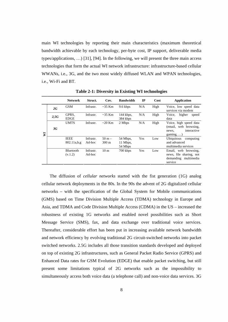
and data traffic over single a single IP-based core network. Table 2-1 summarizes all
8
main WI technologies by reporting their main characteristics (maximum theoretical
bandwidth achievable by each technology, per-byte cost, IP support, deliverable media
types/applications, …) [31], [94]. In the following, we will present the three main access
technologies that form the actual WI network infrastructure: infrastructure-based cellular
WWANs, i.e., 3G, and the two most widely diffused WLAN and WPAN technologies,
i.e., Wi-Fi and BT.
Table 2-1: Diversity in Existing WI technologies
Network Struct. Cov. Bandwidth IP Cost Application
2G GSM Infrastr. ~35 Km 9.6 kbps N/A High Voice, low speed data services via modem
2,5G GPRS, EDGE
Infrastr. ~35 Km 144 kbps, 384 kbps
N/A High Voice, higher speed data
3G
UMTS Infrastr. ~20 Km 2 Mbps N/A High Voice, high speed data (email, web browsing, news, interactive gaming, …)
IEEE 802.11a,b,g
Infrastr.Ad-hoc
50 m – 300 m
54 Mbps, 11 Mbps, 54 Mbps
Yes Low Ubiquitous computing and advanced multimedia services
WI
Bluetooth (v.1.2)
Infrastr.Ad-hoc
10 m 700 kbps Yes Low Email, web browsing, news, file sharing, not demanding multimedia service
The diffusion of cellular networks started with the fist generation (1G) analog
cellular network deployments in the 80s. In the 90s the advent of 2G digitalized cellular
networks – with the specification of the Global System for Mobile communications
(GMS) based on Time Division Multiple Access (TDMA) technology in Europe and
Asia, and TDMA and Code Division Multiple Access (CDMA) in the US – increased the
robustness of existing 1G networks and enabled novel possibilities such as Short
Message Service (SMS), fax, and data exchange over traditional voice services.
Thereafter, considerable effort has been put in increasing available network bandwidth
and network efficiency by evolving traditional 2G circuit-switched networks into packet
switched networks. 2.5G includes all those transition standards developed and deployed
on top of existing 2G infrastructures, such as General Packet Radio Service (GPRS) and
Enhanced Data rates for GSM Evolution (EDGE) that enable packet switching, but still
present some limitations typical of 2G networks such as the impossibility to
simultaneously access both voice data (a telephone call) and non-voice data services. 3G
9
technologies, such as the Universal Mobile Telecommunications System (UMTS) based
on the 3rd Generation Partnership Project (3GPP) in Europe and its counterparts based
on 3rd Generation Partnership Project2 (3GPP2) in the US, are currently under
deployment and provide a flexible global network to enable packet switched
communications by also including simultaneous voice and non-voice data
communications; video calls and live streaming services are two examples of 3G
applications recently launched by mobile telecom companies all around Europe. As
summarized by Table 2-1, those solutions highly differ for achievable bandwidth,
network latency, and IP support availability; in particular, although GPRS and EDGE
are able to provide IP connectivity only last 3G network natively support IP thus
potentially enabling all-over IP transmissions. Finally, let us anticipate that while
cellular networks typically include optimized data-link handoff management of ongoing
voice data flows, i.e., ongoing calls, their support for handoff of other application data
types, e.g., of best-effort over-IP traffic, is usually poor and introduce rather long delays.
IEEE 802.11a/b/g, often referred to with the acronym of Wireless-Fidelity (Wi-Fi)
used to launch IEEE 802.11b on the wireless market, is the de-facto standard for WLAN
deployment since IEEE 802.11b release in 1999. Similarly to other IEEE standards,
IEEE 802.11 specifications define only physical and Medium Access Control (MAC)
layers. Wi-Fi supports infrastructure operating mode and adopts Carrier Sense Multiple
Access with Collision Detection (CSMA/CD) as MAC access method; in the following,
we will give some details about Wi-Fi architecture and its main functions. The standard
defines a Basic Service Set (BSS) as a set of stationary or mobile stations that interact
through one Wi-Fi AP; however, one BSS has a limited geographical coverage
(corresponding to Wi-Fi AP coverage). Hence, the standard introduces also the Extended
Service Set (ESS) defined as a set of BSSs, where the AP communicate among
themselves – through a Distribution System (DS) – to exchange frames for stations in
their BSSs, to forward frames so to follow mobile stations from one BSS to another, and
to exchange frames with wired network. More important, the standard defines a set of
services that divides in station and distribution services. Station services –
authentication, de-authentication, privacy, delivery of data – realize all those functions
that enable secure data delivery, for instance, delivery of data is the reliable delivery of
10
MAC frames with minimal duplication and minimal ordering. Distribution services –
association, disassociation, re-association, distribution, integration – provide services
necessary to allow mobile stations to roam freely within an ESS and allow an IEEE
802.11 WLAN to connect with the wired LAN infrastructure. Distribution services
include all functions necessary to instruct the DS about the current BSS (AP), i.e., to
enable handoff execution; however, the standard does not mandate any time interval for
each of those phases, hence each single vendor can adopt different timing strategies, and
different Wi-Fi card models, although adherent to the standard, may present fairly
different handoff behaviors [67], [93]. For more details about IEEE 802.11, we refer the
interested reader to [98], [42].
Bluetooth (BT) is the de-facto standard for low-cost, short-range radio
communications and has been specified by the Bluetooth Special Interest Group (SIG);
BT has gained large diffusion in the last decade and is actually available on almost any
mobile device [20]. From a logical standpoint, it is not possible to define BT as a pure
infrastructure-based network, i.e., in BT there is no clear distinction between the fixed
BT infrastructure and the mobile nodes, and any client can periodically take the role of
BT AP. In fact, in a BT network, one station has the role of master, and all other BT
stations are slaves. The master decides which slave has access to the channel. The units
that share the same channel – being synchronized to the same master – form a piconet,
the fundamental building block of a BT network. A piconet includes at most 7 active
slave devices that communicate each other under the coordination of a master device and
supports a total address space of 64 devices. In addition, independent piconets that have
overlapping coverage areas may form a scatternet that enables communications (and
multi-hop routing) between nodes belonging to different piconets. BT stack consists of
several different protocol: BT core protocols are BT radio, baseband, Link Manager
Protocol (LMP), Logical Link Control and Adaptation Protocol (L2CAP), and Service
Discovery Protocol (SDP); in addition, BT support a wide range of other protocols and
application profiles to enable BT application development, e.g., the Personal Area
Network (PAN) profile can be used to develop mobile applications over BT using the IP
abstraction. For a detailed description of all protocols and other technological aspects,
we refer the interested reader to [20], [35]. In order to discover and connect BT stations,
11
e.g., to form a new piconet, BT employs two procedures implemented by lower BT
protocol layers: inquiry for discovering other devices and paging to subsequently
establish connections with them. The frequency-hopping nature of BT physical layer
makes the inquiring procedure rather long; in fact, the repeated frequency scans, initiated
by the inquiring node and needed to grant the discovery of all BT devices in the area,
i.e., to complete frequency scanning with high probability, require up to 10,24s. The
subsequent paging phase uses the information collected during inquiry phase to enable
almost instantaneously the communication between the two BT devices. Finally, let us
stress that despite its widespread use, BT SIG has neither defined nor standardized
handoff management mechanisms; hence, recent research efforts, such as BLUEtooth
Public Access (BLUEPAC) and its proposed enhancements, have started to exploit
existing BT functions, such as inquiry and paging, to realize infrastructure-based BT
deployments with possible optimizations of long inquiry and paging intervals [2], [28],
[33].
2.1.2 Mobile Devices: Enhanced Wireless Capabilities and Challenges
WI users are already experiencing the enhanced capabilities and powerful functionality
available into their portable devices and the production costs of electronics is rapidly
decreasing so that powerful communicators, PDAs, and smart phones are becoming
consumer products. Moreover, various wireless technologies are often available on the
same device. Finally, computing power is increasing and operating systems for mobile
devices as well as available programming and execution environments are evolving
rapidly. However, notwithstanding those hardware and software advances, service
delivery towards mobile devices still represents a challenging problem due to several
causes.
Each mobile device presents different (often limited) and highly heterogeneous
hardware and software capabilities:
• processing capabilities (CPU power);
• rendering capabilities (audio, video in/output available) and display size;
• memory and storage space;
12
• operating system (Linux Familiar, Windows-CE, OS X actually available on Apple
iPhones, …);
• programming and execution environments (Windows .NET Compact Framework,
Java2 Micro Edition, …);
• multimedia libraries and frameworks (Windows Media Player Mobile, Java Mobile
Media API, …);
• supported signalling protocols (Session Initiation Protocol, IP Multimedia
Subsystem, …)
• supported multimedia formats (MP3, MP4, H264, …).
Another crucial issue is tackling device mobility and WI heterogeneity (see Table 2-1).
WI mobile devices should be able to autonomously choose the best technology to use at
each time depending not only on wireless network availability, but also on user
preferences and, most important, on service requirements so to be Always Best
Connected (ABC) to the wired inner Internet core. Handoff management introduces
further elements of complexity by requiring not only to choose the best WI access
technology, but also to grant service continuity during device roaming.
Finally, let us consider that current battery technology still requires considerable space
and weight for modest power reserves, the reduction in physical size of portable devices
imposes to provide low power consumption as primary goal. Hence, the reduction of
energy consumption at battery-powered client systems during service provisioning is
critical and represents another key point for the deployment of mobile multimedia
services.
2.1.3 Wireless Communication Impairments
The volatile nature of wireless media – infrared, and especially radio frequency signals –
undermines some of the basic assumptions that are usually made for their wired
counterparts. In the following we first introduce main network QoS impairments that
affect any WI technology; then, we focus on one specific QoS degradation that we will
cover in Chapter 5 – the Wi-Fi anomaly – that affects multimedia provisioning over Wi-
Fi networks.
13
Wireless networks present high packet loss rate due to several possible
interferences. Radio signals can be shielded/absorbed by various objects and materials
and can be interfered by other electrical devices. Each communicating device interferes
with other devices due to the broadcast nature of wireless transmissions and even with
itself due to multi-path self-interference. Finally, well-known problems related to
CSMA/CD-based technologies – hidden and exposed terminal problems – can
undermine packet delivery.
Although great advances in transmission codes and techniques, it is a reasonable
assumption that wireless technology will continue to provide bandwidth at least one
order of magnitude lower than that of fixed networks for some time (see Table 2-1).
Moreover, the goodput – transmission rate experienced and available at the application
layer – experienced by wireless end-nodes is usually much lower than theoretic
bandwidth due to the overhead introduced by lower layer protocols and necessary to
realize robust and reliable transmissions. For instance, notwithstanding IEEE 802.11b
theoretic bandwidth is 11 Mbps, its effective goodput is about 7-7.5 Mbps as verified by
our experimental results (see Chapter 5) and as reported by the literature [48]. Along
with lower bandwidths, wireless networks are also characterized by other degraded
network parameters: longer delay to deliver single data chunks, high delay variability,
i.e., jitter, and long connection setup times due to the time necessary to inquire available
wireless infrastructures and to securely attach to it.
Network conditions can unpredictably vary during the time. Foremost, mobility can
cause intermittent disconnections and handoffs; given the central role that handoff
management covers in this dissertation, we will devote Section 2.3 to define and present
all handoff-related issues and impairments. Besides, mobile devices may interfere with
other static and mobile devices. Finally, received power diminishes with distance thus
whenever a device moves from a well-covered space region to a badly-covered one, all
network QoS parameters introduced above tend to degrade.
Bad coverage conditions are also one of the main reasons of the degradation of Wi-
Fi performance that occurs when there are clients located near the borders of AP
coverage area. More precisely, it is sufficient that one Wi-Fi client is positioned in
proximity of the boundaries of the cell covered by an AP to have a significant
14
degradation of radio channel conditions for not only that client but all nodes in the cell
[96]. This problem, indicated as IEEE 802.11 performance anomaly in the literature, is
due to Wi-Fi automatic data rate adaptation and multiple retransmissions. Nodes located
in low coverage areas cause frequent retransmissions, thus occupying the shared channel
for long time intervals. That reduces the radio resources left to other nodes attached to
the same AP (in the same BSS) even if these nodes are located in good coverage areas.
Indeed, as shown in [48], in presence of IEEE 802.11 anomaly, the goodput of any
station belonging to a BSS is degraded below the data rate experienced by the low-rate
station. Section 5.2 will present our original solution to this crucial Wi-Fi QoS
impairment.
Let us stress that all degradations introduced above affect any service data flow;
anyway, they are particularly detrimental to multimedia streams. In fact, as better
explained in the following section, multimedia streaming imposes QoS constraints on
the delivery of multimedia data chunks, e.g., tolerable delay, tolerable packet loss, and
jitter. These constraints must be respected for the whole duration of service provisioning
to grant a valuable experience to served users.
2.2 Multimedia Services
Multimedia services are central in several different application areas that span from
traditional telecom services — such as Voice over IP (VoIP) and video conference — to
entertainment — such as on-line gaming, audio/video news broadcasting, music
distribution, and Video on Demand (VoD) — and to other novel challenging areas with
even stricter QoS requirements like health-care and mission critical applications — such
as online patient monitoring and video surveillance. This section defines general
multimedia service requirements and main application types, by focusing especially on
mobile multimedia deployment.
2.2.1 Multimedia Provisioning and QoS Management
The diffusion of multimedia services and the competition among WI service providers
stress innovative service properties more and more important for application/service
providers, network operators and final customers. The key property is QoS, defined as
15
the possibility to grant and guarantee negotiated service levels independently of the
dynamic conditions of resources in all the involved networks and systems [1], [27].
By delving into finer details, multimedia systems must respect real-time deadlines
for the processing, delivery, and playback of each single multimedia data chunk.
Multimedia flows (audio, video, data, …) consist of single periodically changing values
of multimedia data that we define (independently of their multimedia type) frames. Each
frame must be represented (at the client side) by a well-determined deadline, usually
defined playback time; delay and jitter are allowed, but only before the final presentation
to the user [89]. In other words, after playback starts, whenever a frame misses its
playback time, the audio/video playback experiences some form of distortion that can be
less or more severe depending on the number of consecutive frames that miss their
deadlines.
Two major approaches to QoS management exist today and can be applied either
separately or simultaneously: reservation-based and adaptive-based. The first one
guarantees the QoS level by exploiting negotiation and reservation protocols to ensure
the availability of the needed amount of resources (at each individual service
components participating to multimedia flows processing and communication) before
multimedia streaming starts. Internet Engineering Tack Force (IETF) Integrated Services
(IntServ) architecture and ReSerVation Protocol (RSVP) are good examples of this fist
approach [21]. The second one tries to respect the specified QoS requirements without
any guarantee of satisfaction, by monitoring the available QoS and by scaling and
adapting ongoing media flows to fit actual system conditions, such as actual CPU load or
network traffic. For instance, IETF Differentiated Service (DiffServ) architecture is a
good example of this second approach [19].
Let us stress again that, independently of the adopted QoS approach, the key
property to grant service usability and user satisfaction is to continuously monitor and
manage QoS and system resources for the whole duration of the multimedia interaction.
We define multimedia session (or simply session) the time interval between the
establishment of the multimedia interaction, e.g., the initiation of a phone call, and its
termination, e.g., phone call termination; we define also session continuity (or service
16
continuity) as the property of guaranteeing the respect of frame playback times for the
whole duration of the multimedia session.
By adopting the two definition introduced above, QoS management operations can be
broadly divided into reservation functions, usually applied at multimedia session
initiation time, and adaptation functions, applied as needed during multimedia session
[89]. The main reservation functions are:
• Specification: the definition of the agreement between provider and customer about
QoS requirements and capabilities and service delivery characteristics;
• Negotiation: the process of reaching an agreed specification between all parties;
• Scaling: the execution of all adaptation methods required to massage deliver
multimedia flows so to fit agreed QoS specifications – enforced through static
resource reservation, as better explained below. In particular, those methods can be
classified as transparent, when they can be applied independently from upper
protocol and application layers, e.g., by adopting frame dropping techniques, and as
non-transparent when they require interaction of the transport system with the upper
layers, e.g., to modify the media stream before it is presented to the transport layer;
• Admission control: the comparison of required QoS and capability (system and
communication resources) to meet requirements;
• Resource reservation: the allocation of resources to connections, streams, and so
forth.
Adaptation functions, instead, includes:
• Traffic shaping and control: all those activities aimed to profile and control
multimedia flow transmissions at ingress network nodes and/or inside the network;
• Monitoring: the continuous measure of QoS actually provided by the network and by
end-systems. There are two main approaches to QoS and resource monitoring: re-
active and pro-active: the former means that monitoring entities emit QoS status
reports/indications only after monitored QoS parameter has degraded, the latter
instead aims to pro-actively notify that QoS is degrading before degradation effects
occur;
• Renegotiation: the redefinition of the QoS contract triggered either by the user, e.g.,
by changing some QoS threshold, by end-systems, e.g., due to overload of a
17
multimedia server, or the network (or other intermediate hosts collaborating to
service delivery) due to congestion or abrupt changes of resource availability, e.g.,
during the handoff from a Wi-Fi network to a GPRS one;
• Adaptation: the adaptation of the application to changes in the QoS of the system,
possibly after renegotiation; adaptation methods, such as scaling ones, can be
transparent or non-transparent. However, adaptation is more complex than scaling
and is probably one of the most challenging QoS operations. In fact, it requires to
dynamically modify the provisioning of an ongoing multimedia flow – by acting at
transport and upper layers, up to the application layer – by possibly masking all those
management actions to the final user, i.e., by granting session continuity.
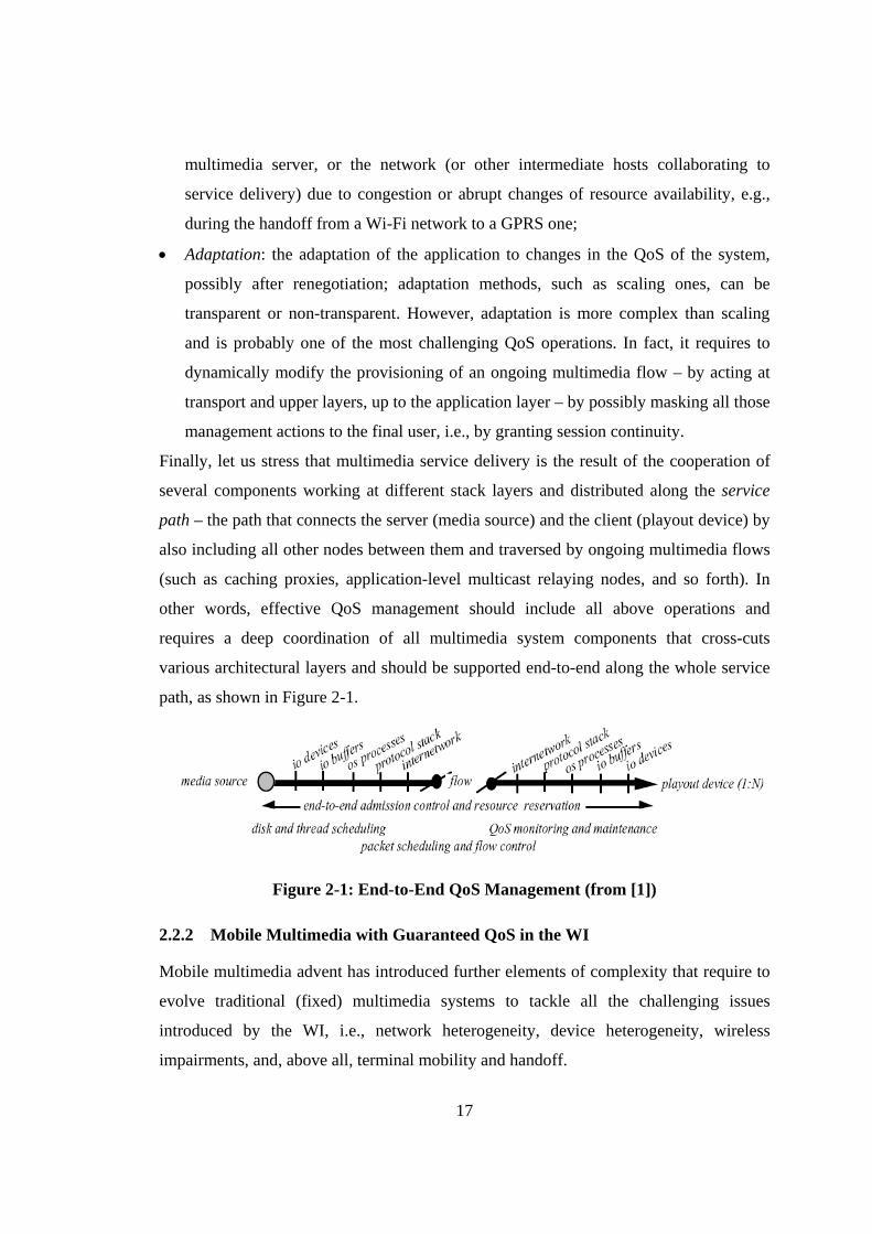
Finally, let us stress that multimedia service delivery is the result of the cooperation of
several components working at different stack layers and distributed along the service
path – the path that connects the server (media source) and the client (playout device) by
also including all other nodes between them and traversed by ongoing multimedia flows
(such as caching proxies, application-level multicast relaying nodes, and so forth). In
other words, effective QoS management should include all above operations and
requires a deep coordination of all multimedia system components that cross-cuts
various architectural layers and should be supported end-to-end along the whole service
path, as shown in Figure 2-1.
Figure 2-1: End-to-End QoS Management (from [1])
2.2.2 Mobile Multimedia with Guaranteed QoS in the WI
Mobile multimedia advent has introduced further elements of complexity that require to
evolve traditional (fixed) multimedia systems to tackle all the challenging issues
introduced by the WI, i.e., network heterogeneity, device heterogeneity, wireless
impairments, and, above all, terminal mobility and handoff.
18
Mobile multimedia provisioning requires a deep change of traditional QoS
management perspective: traditional multimedia system, in fact, adopt a reservation-
based approach and consider QoS adaptation as an infrequent management event that
occurs only during overload/congestion situations; mobile multimedia systems, instead,
should consider QoS management by adaptation the norm; moreover, they should be
pro-active to promptly the frequent and abrupt QoS changes that occur in the WI
provisioning environment [89], [57], [10].
Device mobility may cause losses of communication, due to possible handoffs, due
to blind spots under bridges, behind buildings or hills, and so forth. Guaranteeing service
continuity notwithstanding handoffs, sporadic data losses, and possible access
technology change while a multimedia session is proceeding, is a challenging task that
requires an evolving process of traditional QoS adaptation methods that were generally
more static and highly optimized for well known and less dynamic provisioning
scenarios [69], [55], [18] .
Traditional (static) resource reservation techniques have to be evolved. Approaches
have been proposed to reserve needed resources in advance, by gathering information on
the neighboring cells and by exploiting movement prediction [49], [23]. We also claim
that it is necessary to enable autonomous and proactive migration of multimedia data
chunks already arrive at the old cell towards possible target cells so minimize QoS
degradations due to the handoff by quickly re-starting multimedia provisioning as the
client device re-connects to the target cell after an handoff [10].
Delivery of high quality multimedia contents is problematic for mobile devices due
to their limited processing, memory, and rendering capabilities; hence, QoS tailoring in
the mobile Internet scenario must allow for scaling of delivered information to
dynamically adapt the content format and presentation to the properties of the current
access terminal. Multimedia data processing and transmission are power-intensive
activities that can easily drain all battery power available at the client device; hence,
energy management should be considered among other crucial QoS aspects. In a more
detailed view, among the components of a mobile device that contribute to drain battery
power, the impact of wireless transmissions has been widely recognized to be one of the
most relevant and its relevance increases as the mobile device size decreases, e.g.,
19
passing from full-fledged laptops to PDAs. Hence, effective power management
strategies should focus on optimization of the energy consumption of all wireless
network interfaces available client mobile terminal, especially for the provisioning of
multimedia content.
Finally, QoS management should continue to tackle more traditional QoS
degradations, e.g., due to network congestions, and should address novel impairments
introduced by the WI, i.e., intermittent packet losses, high delays and jitters, goodput
degradations (and Wi-Fi anomaly), and more nervous network condition variations.
All above management operations can potentially complicate the development of
mobile multimedia applications; thus it is crucial to demand QoS management from the
service level to a separate layer, the middleware layer. To do this, it is crucial to
introduce simple mechanisms to communicate service-level needs to the middleware
level. The next section details main requirements and mechanisms needed to enable QoS
specification, so to define agreements between service and middleware levels about
service delivery characteristics; then, it will define main multimedia types by means of
their different requirements.
2.2.3 QoS Specification and Main Multimedia Application Types
QoS specification involves a multitude of properties beyond the application-specific
aspects, including performance characteristics, availability, responsiveness,
dependability, security, and adaptability. [53] surveys several different research efforts
and characterizes QoS specifications as follows.
First, QoS specifications should allow for descriptions of quantitative QoS
parameters (jitter, delay, bandwidth, …) and qualitative QoS parameters, such as CPU
scheduling policy and error recovery mechanisms, as well as adaptation rules; second,
they must be declarative in nature – that is, to specify only what is required but not how
the requirement should be carried out; finally, QoS specifications need to be
accompanied by a mapping process to translate the QoS specification (declared by the
service level) to underlying system mechanisms and policies (realized by the middleware
level).
20
Moreover, since QoS management cross-cuts and requires to act at different layers,
it is possible to partition QoS specifications depending on what layer they refer to. User-
layer specifications let the user specify, at an abstract level, the quality expected from an
active application; for instance, the user could indicate that, for a specific service, she
desires a “good” quality. Clearly such qualitative evaluation is usually difficult to
translate in more objectives (quantitative) scores; nonetheless, some novel techniques
and tools are exploring the possibility to define objective and simple QoS indicators to
ease the definition of objective user-layer specifications. For instance, the Video Quality
Metric (VQM) proposes a QoS simple indicator, a normalized value that varies between
0 and 1, to measure the QoS of a video transmitted over the network (see Subsection
5.1.1 for more details) [97]. Later on it is, necessary to translate the human-perceptive
quality into more concrete QoS parameters, usually called application-layer QoS
specifications. This first mapping between user and application QoS specifications
assumes no knowledge of the underlying operating system and network conditions;
Service Level Specifications (SLS) introduced below are a good example of such
specification. Finally, for the application to be executed on an OS platform and a
physical network, application-layer specification must be mapped into more concrete
resource requirements (bandwidth, memory allocation, …), i.e., resource-layer QoS
specifications, usually defined Service Level Agreements (SLA), as explained in the
following.
Given those general framework and definitions; in the rest of this thesis, we will
adopt a more technical definition proposed by IETF that distinguish SLS (application-
layer specification) defined as service requirements independent of underlying network
parameters, technologies, and domains; and SLA (resource-layer specification) defined
as a legal contract between a customer and a service provider that specifies that contains
all legal arrangements for the service subscription [19], [46]. SLS are crucial in the WI
scenario since they let the service layer specify its requirements to the middleware layer
independently of underlying wireless access technologies; by delving into finer details,
SLS usually specify four crucial parameters:
• Throughput: usually it is expressed in byte or frame per second, and expresses the
quantity of data that the multimedia system is expected to serve in the time unit;
21
• Tolerable delay: represents the delay between the stream at the supplier and the
stream at the consumer;
• Tolerable jitter: represents the variation between time relation between frame
playback times;
• Data losses: the maximum number of frames that can be lost without compromising
playback QoS at the consumer.
Different standardization bodies, such as IETF and 3GPP, have proposed possible
taxonomies to distinguish application types with regards to their service requirements. In
this thesis we will adopt the framework proposed by 3GPP that defines four main
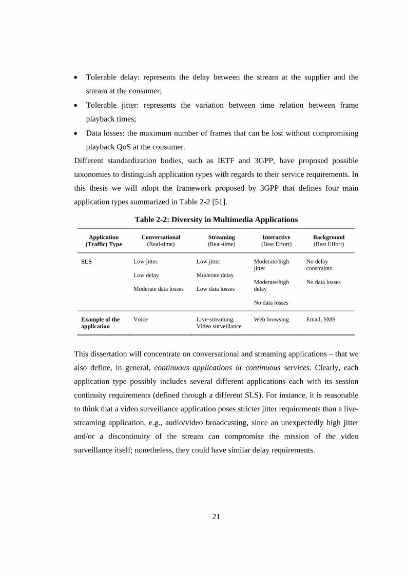
application types summarized in Table 2-2 [51].
Table 2-2: Diversity in Multimedia Applications
Application (Traffic) Type
Conversational (Real-time)
Streaming (Real-time)
Interactive (Best Effort)
Background (Best Effort)
SLS Low jitter Low delay Moderate data losses
Low jitter Moderate delay Low data losses
Moderate/high jitter Moderate/high delay No data losses
No delay constraints No data losses
Example of the application
Voice Live-streaming, Video surveillance
Web browsing Email, SMS
This dissertation will concentrate on conversational and streaming applications – that we
also define, in general, continuous applications or continuous services. Clearly, each
application type possibly includes several different applications each with its session
continuity requirements (defined through a different SLS). For instance, it is reasonable
to think that a video surveillance application poses stricter jitter requirements than a live-
streaming application, e.g., audio/video broadcasting, since an unexpectedly high jitter
and/or a discontinuity of the stream can compromise the mission of the video
surveillance itself; nonetheless, they could have similar delay requirements.
22
2.3 Handoff Management
As we have anticipated in the previous section, handoff management is a crucial and
novel QoS management requirement for the support of mobile multimedia over WI
networks. In fact, WI networks have the ultimate goal of supporting the roaming of
mobile devices among several different wireless infrastructures and of providing access
to each mobile device regardless of the particular wireless technology it exploits.
Nonetheless, a general support infrastructure able to grant session continuity during
handoffs is still missing. This section defines handoff management terminology,
introduces main handoff impairments, and overviews main challenges and claims related
to the handoff management of mobile multimedia.
2.3.1 Handoff Terminology
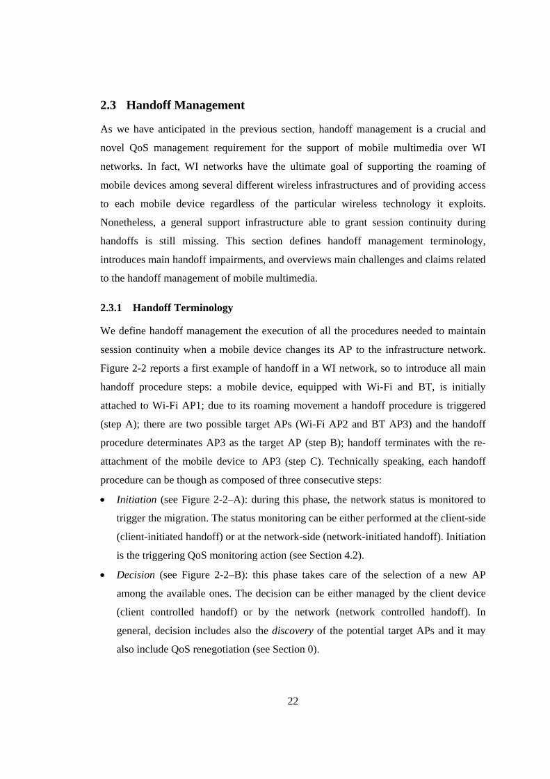
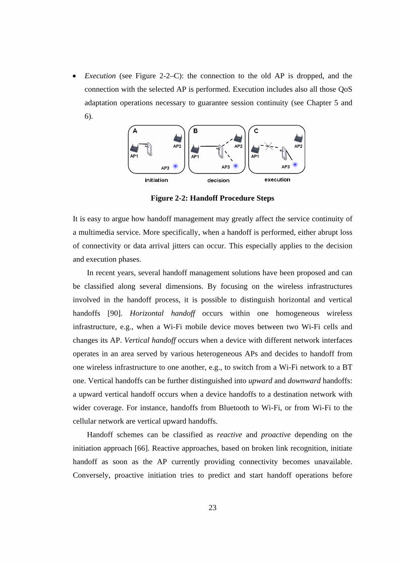
We define handoff management the execution of all the procedures needed to maintain
session continuity when a mobile device changes its AP to the infrastructure network.
Figure 2-2 reports a first example of handoff in a WI network, so to introduce all main
handoff procedure steps: a mobile device, equipped with Wi-Fi and BT, is initially
attached to Wi-Fi AP1; due to its roaming movement a handoff procedure is triggered
(step A); there are two possible target APs (Wi-Fi AP2 and BT AP3) and the handoff
procedure determinates AP3 as the target AP (step B); handoff terminates with the re-
attachment of the mobile device to AP3 (step C). Technically speaking, each handoff
procedure can be though as composed of three consecutive steps:
• Initiation (see Figure 2-2–A): during this phase, the network status is monitored to
trigger the migration. The status monitoring can be either performed at the client-side
(client-initiated handoff) or at the network-side (network-initiated handoff). Initiation
is the triggering QoS monitoring action (see Section 4.2).
• Decision (see Figure 2-2–B): this phase takes care of the selection of a new AP
among the available ones. The decision can be either managed by the client device
(client controlled handoff) or by the network (network controlled handoff). In
general, decision includes also the discovery of the potential target APs and it may
also include QoS renegotiation (see Section 0).
23
• Execution (see Figure 2-2–C): the connection to the old AP is dropped, and the
connection with the selected AP is performed. Execution includes also all those QoS
adaptation operations necessary to guarantee session continuity (see Chapter 5 and
6).
Figure 2-2: Handoff Procedure Steps
It is easy to argue how handoff management may greatly affect the service continuity of
a multimedia service. More specifically, when a handoff is performed, either abrupt loss
of connectivity or data arrival jitters can occur. This especially applies to the decision
and execution phases.
In recent years, several handoff management solutions have been proposed and can
be classified along several dimensions. By focusing on the wireless infrastructures
involved in the handoff process, it is possible to distinguish horizontal and vertical
handoffs [90]. Horizontal handoff occurs within one homogeneous wireless
infrastructure, e.g., when a Wi-Fi mobile device moves between two Wi-Fi cells and
changes its AP. Vertical handoff occurs when a device with different network interfaces
operates in an area served by various heterogeneous APs and decides to handoff from
one wireless infrastructure to one another, e.g., to switch from a Wi-Fi network to a BT
one. Vertical handoffs can be further distinguished into upward and downward handoffs:
a upward vertical handoff occurs when a device handoffs to a destination network with
wider coverage. For instance, handoffs from Bluetooth to Wi-Fi, or from Wi-Fi to the
cellular network are vertical upward handoffs.
Handoff schemes can be classified as reactive and proactive depending on the
initiation approach [66]. Reactive approaches, based on broken link recognition, initiate
handoff as soon as the AP currently providing connectivity becomes unavailable.
Conversely, proactive initiation tries to predict and start handoff operations before
24
disconnection takes place (when the origin AP is still available). Proactive initiation can
trigger a migration procedure with respect to several criteria, such as monitoring the
Receiver Signal Strength Indicator (RSSI), using a set of defined quality parameters, and
using a user-driven triggering. In the class of RSSI-based schemes, most proactive
solutions are based on a fixed threshold mechanism, that is, the handoff is initiated when
the RSSI falls below a certain threshold. Other solutions exploit more complex RSSI
processing, e.g., fuzzy controllers or mobility prediction [66], [10].
By adopting a classification typically used to accommodate MIP extensions, it is
possible to distinguish three geographical scopes for handoffs: micro, macro, and global
[25], [78]. Micro handoff (intra-subnet handoff) includes only data-link layer handoff
and relates to clients that roam between two different APs without changing their IP
addresses. Macro handoff (intra-domain handoff) refers to clients that move between
two wireless APs attached to different IP subnets and includes network-layer handoff
with changes in client IP address. Global handoff (inter-domain handoff) relates to
mobile clients that roam between two APs attached to different Internet domains and
requires not only address change but also transfer of user Authentication, Authorization,
and Accounting (AAA) data, needed when entering a new access domain.
One further distinction is between hard and soft handoffs. If mobile devices are
allowed to have two or more simultaneous connections to different APs, then the
handoff is said to be soft; otherwise it is defined as hard [78]. This distinction applies to
the decision and execution steps: the decision and/or the execution can be thus be
performed either while the device is already disconnected from the old AP (hard
handoff) or while the device is still connected to the old AP (soft handoff). Handoff
schemes with reactive initiation are an example of hard handoffs, whereas proactive
approaches can be either hard or soft. Soft handoffs have the advantage of providing
better service continuity than hard handoff. Specifically, while they can still cause
arrival delays, they reduce the occurrence of data losses. On the other hand, they result
in more power consumption at client nodes – they require maintaining multiple active
wireless connections simultaneously. Finally, while above definition usually applies to
the data-link layer, we can use it also for upper layers, and in particular for the
middleware/application layer. As compared to a strict physical/data-link-layer solution,
25
upper-layer solutions (especially application-layer ones) can adaptively take advantage
of both the two different handoff schemes. Specifically an application can either
implement multiple use of network interfaces (soft handoff) or adopt only one network
interface at time (hard handoff), depending on its particular requirements and run-time
conditions.
2.3.2 Handoff Impairments
Previous sections have already introduced main wireless impairments that can
compromise service continuity and mobile multimedia deployment over WI networks; in
this section introduces and defines main impairments due to the dynamic execution of
handoff procedures.
Handoff latency is the main handoff-related QoS parameter. We will thereafter refer
to handoff latency as the time needed for the completion of decision and execution steps.
We define main handoff latency factors as follows: handoff discovery time is the time for
probing available wireless infrastructures to discover possible target APs; handoff
decision time is the time for selecting which is the best wireless target technology and
the next (target) AP where the device will attach, and to decide necessary (application-
layer) handoff management countermeasures, e.g., if it is necessary to downscale
multimedia flows during a vertical handoff; and handoff execution time, i.e., the time re-
establishing ongoing multimedia session with the target AP, including the execution of
necessary adaptation operations and all other application management operations needed
to grant session continuity.
The other main QoS parameter is packet loss defined as the quantity of transmitted
data packets or frames lost during the handoff transitory. Packet loss depends on both
handoff latency and adopted buffering techniques; for instance, intermediate network
buffers could be interposed between the server and the client to smooth packet losses.
Hard handoff procedures provoke temporary disconnections and are thus more prone to
packet losses.
Handoff latency and packet loss depend with large variation on technological
constraints – for instance, as we introduced in Subsection 2.1.1, Wi-Fi handoff discovery
and decision phase are highly dependent wireless card vendor/model – and on employed
26
handoff management protocols/procedures at all different layers. During the handoff
latency period, both packets losses – especially in the case of hard handoff – and
excessive packet delivery delays – even in the case of soft handoff – may be
experienced. Vertical handoffs exacerbate the problem since they require either macro or
global handoff management and include more management actions, thus stretching
handoff latency. Above handoff-related impairments can undermine the provisioning of
any application type, but they are especially detrimental to conversational and streaming
applications due to their strict delay, jitter, and data loss requirements.
2.3.3 Mobile Multimedia Handoff Management: Challenges
Guaranteeing session continuity to roaming clients is a challenging task that complicates
application design and implementation. Much work has already been done in this area.
However, state-of-the-art research efforts address service continuity via dedicated
approaches retailed on specific application scenarios or on specific wireless technologies
with a limited applicability to restricted use cases [5], [47], [61]. Quite the opposite, this
thesis claims that effective handoff management can be obtained only through a
thorough coordination of several handoff management actions at different layers. In
other works, handoff management should be based on the so called cross-layer approach,
i.e., the handoff procedure is handled simultaneously as a whole at more than one
protocol stack layers, and should be able to exploit and integrate with existing network
protocols and application deployments so to guarantee session continuity to WI roaming
clients.
Indeed, apart different application requirements, the high heterogeneity of wireless
technologies is one of the main limiting factor that complicates the development of
general (technology-independent) handoff countermeasures [11]. In fact, if we focus on
card model/driver differences, each wireless card adopts different QoS scales and values,
notwithstanding the large agreement on the type of main wireless network monitoring
parameters. Moreover, each wireless technology, and often even each wireless card
model/driver, implements its own set of parameters, mechanisms, and handoff
procedures (hard/soft, proactive/reactive, …). For instance, Wi-Fi implements hard
handoff, while BT lets application implement both hard and soft schemes [98], [2], [33].
27
All these differences greatly impact vertical handoff management process. The different
handoff strategies should be taken into account for every possible couple of wireless
technologies one is interested in to. In addition, even implementing simple monitoring or
communication tasks over heterogeneous networks requires wireless network
programmers to know all the peculiarities of each different wireless technology. As a
simple example, the Wi-Fi received signal strength can be obtained through the
iwconfig command in Linux [91], while the same value for BT in Linux is gathered
trough a specific primitive of the BlueZ stack [100].
By considering traditional multimedia streaming solutions, let us note that, even
when equipped with a buffering strategy, they hardly accomplish the task of delivering
high quality streams in the presence of handoffs. Client-side data buffering is a
commonly followed solution in multimedia streaming over wired networks, in order to
smooth possible congestions along the client-to-server path. In the context of wireless
networks, client-side buffers are crucial to continue providing multimedia frames to
local players. For instance, client-side buffers are fundamental to smooth jitters due to
temporary wireless channel degradation. However, by focusing on handoff management,
the solution of pre-fetching a large chunk of multimedia flow at the client side, so as to
cover the handoff latency and to start receiving the stream from the new AP, is often not
viable [41]. Client-side buffering requires client node to contact its corresponding server
for each handoff (so as to trigger necessary handoff management countermeasures) and
would be effective only if the round-trip time between client and server nodes is lower
than continuous service delay requirements.
Finally, traditional one-side buffering architectures complicate the execution of
advanced handoff procedures and increase network load. For instance, soft handoff
management requires duplicating the multimedia flow over two different wireless
interfaces; hence, remote servers must send twice the same information across the
network, thus increasing server and network overhead; similarly, hard handoff requires
re-transmitting all those data already sent toward the client node and lost during handoff
disconnection. Finally, traditional end-to-end fixed Internet client/server architecture
may wrongly perceive client-side handoff impairments, especially packet losses, as
network failures, such as in the notable case of TCP connections that incur in congestion
28
control mechanisms [26]. Similarly, those misleading monitoring information might lead
multimedia streaming applications to downscale/degrade delivered multimedia content.
2.4 Chapter Conclusions
In this chapter we have provided an overview of the main concerns related to the
deployment and the management of Internet-based services over the WI, in particular
when they present multimedia QoS requirements and are supplied to mobile terminals.
Starting from the description of the WI infrastructure and main wireless impairments, we
have described main QoS management operations and mobile multimedia requirements.
Then, we focalized on the handoff management process identifying main handoff steps
and QoS degradations; finally, we presented main challenges and claims related to the
handoff management of mobile multimedia services in the WI environment.
The next chapter will analyze the requirements of a handoff middleware targeted to
support session continuity in the WI provisioning scenario. In particular, we will discuss
the suitability of our novel full context-aware approach, and then we will present the
main design guidelines for the implementation of MUM, our middleware for mobile
multimedia handoff management. The chapter will end with an overview of the MUM
architecture that introduces the service components, which will be described more
deeply in Chapters 4, 5, and 6.
29
3. A Full Context-Aware Middleware Architecture for Handoff Management
The provisioning of mobile multimedia service with session continuity guarantees is a
challenging task that requires to solve all the issues presented in the previous chapter and
complicates services design and implementation. To ease multimedia services
development, and to provide flexible solutions to service continuity, we claim the need
of a middleware-based approach – handoff middlewares. Handoff middlewares should
relieve WI applications of handoff management burden by transparently taking over
service continuity responsibility and should be able to effectively handle WI handoffs
irrespectively of underlying wireless technologies. To do this, handoff middlewares
should be implemented at the application level.
The application level is recognized as the most suitable to provide flexible solutions
to crucial mobility issues, e.g., application-specific caching and filtering, QoS
management, and interoperable session control [4], [79]. Let us introduce some of the
benefits that application-level support solutions can provide with an example. Consider
two users, Alice and Bob, who have subscribed for the same video broadcasting service
to watch daily news while commuting by bus. The video broadcasting service is
delivered through a WI network composed by Wi-Fi hotspots, deployed at the bus
station and at bus stops, and by a UMTS infrastructure deployed over the traversed city
districts. Bob accesses the service from his full-fledged laptop and has subscribed for
gold quality, i.e., maximum resolution and best possible network QoS, while Alice
exploits a Personal Digital Assistant (PDA) and has subscribed for a bronze quality level
(small frame size and no guarantees at all on network QoS). One day, Alice and Bob are
sitting on the same bus and using the service when a vertical handoff between the Wi-Fi
and the UMTS networks occurs due to the bus leaving the Wi-Fi enabled station.
Application-level middleware infrastructures can react to the discontinuity in available
bandwidth by properly adapting multimedia provisioning depending on the differentiated
profiles of Alice and Bob: Bob’s received video frames should become smaller while he
continues to access the broadcasting service; Alice should have her service downscaled
to only-audio streaming.
30
Only application layer handoff middlewares present the necessary flexibility and
expressiveness to enable effective service coordination, tailored to specific application
domains. Let us state that lower-layer handoff management solutions could not take
service-dependent decisions; instead, the adoption of an application-level approach
allows handoff middlewares to perform some handoff management operations
selectively, e.g., only for WI multimedia flows. This also enables diverse handoff
treatments depending on differentiated SLAs.
In addition, effective handoff management solutions should have full visibility of all
those characteristics that describe service execution environments and enable handoff
management operations aimed to adapt service provisioning to actual system conditions.
That visibility of handoff-related context information is essential to grant session
continuity. In particular, context-aware service continuity solutions should exhibit three
enabling properties: i) handoff awareness to enable effective management actions via
full visibility of employed handoff procedures and parameters; ii) QoS awareness to
actively participate to the management of service components according to service
requirements and QoS degradation due to handoffs; and iii) location awareness to enable
runtime decisions based on client mobility, network topology, and current resource
position.
This remainder of this chapter is organized as follows: the first section introduces
our novel full context awareness model for mobile multimedia handoff management; the
second and the third sections introduce main handoff management requirements and
middleware design guidelines; and the fourth section sketches MUM middleware
architecture and its main components.
3.1 Full Context-Awareness Handoff Management Approach
Granting service continuity is a complex task due to all dimensions that may influence
handoffs. In fact, the heterogeneity of the WI deployment scenario (wireless
technologies, client devices, mobility support, …), along with all issues that can
characterize specific handoff procedures, call for the complete visibility of all aspects
related to the handoff process in order to successively undertake handoff management

31
actions. In other words, there is the need to consider solutions based on full context
awareness.
A large number of research proposals and practical solutions have recently emerged
to tackle service continuity, each with specific goals, advantages, and limitations (see
also Chapter 7 with all main related research efforts). However, while different handoff
solutions in the literature typically share similar functional requirements and adopt
similar mechanisms, there is no classification framework to analyze and classify
different requirements and approaches. That lack makes it difficult to compare different
systems and motivates why a set of common and standardized design guidelines for the
development of novel infrastructures for WI handoff is still missing.
Therefore, it could be useful to sketch a taxonomy for clarifying main handoff
challenges and for classifying handoff characteristics. In particular, our classification
adopts handoff, QoS, and location awareness as three main criteria. Any handoff
solution, to operate management countermeasures to effectively guarantee service
continuity, has to be aware of handoff procedure properties and occurrence, of QoS
degradations introduced by handoffs, and of client mobility and resource availability
within WI access localities.
3.1.1 Handoff Awareness
Let us consider one user who moves with her BT- and Wi-Fi-enabled PDA, getting out
from her BT-covered office and entering a large hall served with Wi-Fi, while she is
making a phone call.
Handoff awareness is the ability to have full visibility of supported handoff types
and handoff management strategies. Handoff awareness is crucial to decide effective
handoff management actions depending on local WI environment and to enable
automatic execution of management operations necessary to grant service continuity.
Handoff awareness includes three main parameters. The first one is the direction of
the handoff; by using the definition introduced by the previous chapter our model
distinguishes horizontal and vertical handoffs.
The second parameter, i.e., initiation, differentiates reactive and proactive handoff
procedures. We have already defined handoff initiation in the previous chapter; here, we
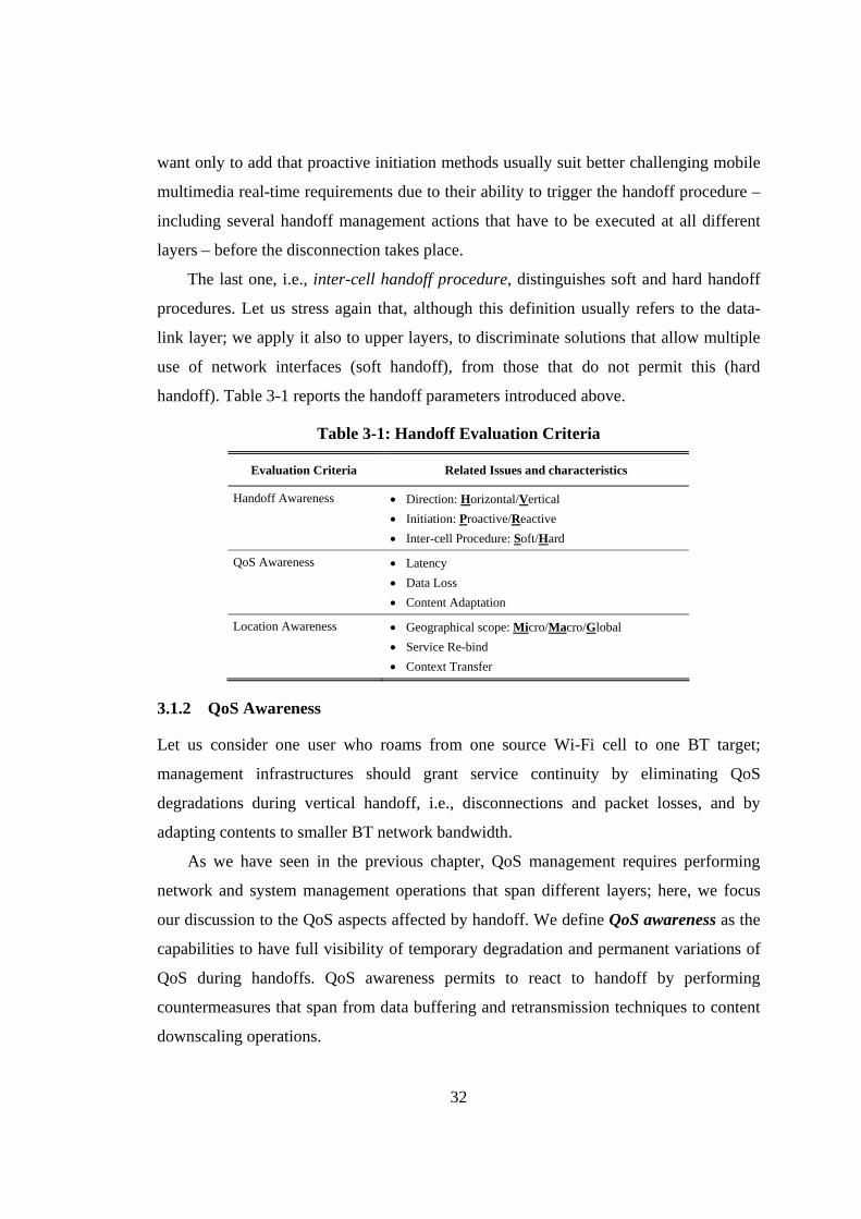
32
want only to add that proactive initiation methods usually suit better challenging mobile
multimedia real-time requirements due to their ability to trigger the handoff procedure –
including several handoff management actions that have to be executed at all different
layers – before the disconnection takes place.
The last one, i.e., inter-cell handoff procedure, distinguishes soft and hard handoff
procedures. Let us stress again that, although this definition usually refers to the data-
link layer; we apply it also to upper layers, to discriminate solutions that allow multiple
use of network interfaces (soft handoff), from those that do not permit this (hard
handoff). Table 3-1 reports the handoff parameters introduced above.
Table 3-1: Handoff Evaluation Criteria
Evaluation Criteria Related Issues and characteristics
Handoff Awareness • Direction: Horizontal/Vertical • Initiation: Proactive/Reactive • Inter-cell Procedure: Soft/Hard
QoS Awareness • Latency • Data Loss • Content Adaptation
Location Awareness • Geographical scope: Micro/Macro/Global • Service Re-bind • Context Transfer
3.1.2 QoS Awareness
Let us consider one user who roams from one source Wi-Fi cell to one BT target;
management infrastructures should grant service continuity by eliminating QoS
degradations during vertical handoff, i.e., disconnections and packet losses, and by
adapting contents to smaller BT network bandwidth.
As we have seen in the previous chapter, QoS management requires performing
network and system management operations that span different layers; here, we focus
our discussion to the QoS aspects affected by handoff. We define QoS awareness as the
capabilities to have full visibility of temporary degradation and permanent variations of
QoS during handoffs. QoS awareness permits to react to handoff by performing
countermeasures that span from data buffering and retransmission techniques to content
downscaling operations.
33
Handoff latency is the main QoS-related parameter: it measures handoff latency
time so to let the handoff middleware dimension correctly the system resources for
handoff management. For instance, it is highly useful to dimension the buffer/s
interposed between client and server to grant session continuity (see Subsection 5.1.2).
Hence, correct estimation handoff latency is crucial to grant session continuity.
Packet loss measures the quantity of data lost during handoff transitory. Packet loss
depends on both handoff latency and possibly adopted buffering techniques. In
particular, this context model parameter distinguishes those handoff management
solutions that tackle packet loss management from those that do not consider that aspect.
Content adaptation is the ability of dynamically tailoring delivered contents in
response to drastic bandwidth changes — typically due to vertical handoffs. For
instance, vertical handoff from Wi-Fi to BT provokes a sudden bandwidth drop: it
requires prompt QoS reduction of all multimedia flows exceeding BT network capacity
in order to avoid congestion. Table 3-1 sums up the QoS parameters reported above.
3.1.3 Location Awareness
Let us consider one user who, when accessing a news service, moves from university to
home; during her roam, she changes her WI provider switching from her department Wi-
Fi network to the public cellular network. Handoff management infrastructures should
maintain service provisioning by passing context information from the old to the new
provider and by configuring local resources available in the new provider domain.
Location awareness is the visibility of client location, WI access domain, and local
resources, i.e., which domain/network configuration changes will occur due to handoff,
which resources are available to support service continuity at WI access localities, and
how roaming client can exploit them. That awareness also permits to transfer context
data when clients move.
Handoff geographical scope, introduced in Subsection 2.3.1, indicates the ability to
tackle handoffs that overcome the local network scope (micro), by also including IP
address change (macro), or Internet domain change (global).
Service re-bind is the capacity to dynamically re-connect clients to resources and
service components at the WI access localities where the clients are moving to. In
34
particular, it refers to the ability to discover, locate, and dynamically re/bind roaming
clients to those local resources. For instance, specific local mediators such as enhanced
wireless APs or application proxies, could be available within the WI localities to assist
roaming clients during handoffs, with buffering, data retransmission, and content
adaptation. The handoff support should be able to autonomously bind clients to those
local mediators [10].
Context transfer is the capacity to move context information between fixed
infrastructure and client mobile node and from origin to target locality. Context transfer
is crucial to finish re-configuration operations (spanning from client node re-addressing
and AAA operations to mediator activation) before actual handoff execution. While
context transfer is considered an enabling factor towards WI location-aware distributed
infrastructures by both academia and industry [7], [63], the context definition adopted in
literature is rather poor and incomplete. If it usually includes only AAA information, we
claim it is necessary to be able to update all context data that describes handoff status,
i.e., handoff, QoS, and location information.
Based on the above evaluation of the different aspects of handoff, QoS, and location
awareness which affect the handoff management process, we propose the taxonomy of
Table 3-1. The rest of the thesis uses this taxonomy to draw the design guidelines for the
development of context-aware handoff management solutions and to collocate MUM
original contributions.
3.2 Handoff Management Requirements
We claim that the full visibility of handoff, QoS, and location information is essential to
dynamically adapt and tune service continuity depending on current executing
conditions (handoff type, latency, geographical scope, …). The three core requirements
for novel context-aware handoff solutions are pro-activity, adaptiveness, and
reconfigurability.
First, handoff solutions should be proactive, in other words, it should foresee
handoff occurrence. Because handoff management operations can be long, service
continuity management should prepare actions and countermeasures as early as possible.
Handoff awareness enables pro-activity; in particular, handoff solutions should notify
35
horizontal and vertical handoff predictions and trigger handoff management actions in
advance.
Handoff solutions should be adaptive by exploiting QoS awareness to dynamically
suit handoff occurrence. In particular, for us adaptation is the ability to dynamically
adjust and massage multimedia flow provisioning to obtain service continuity. Handoff
latency awareness is crucial, coupled with visibility of service requirements, to select
and dimension handoff management procedures: for instance to choose hard/soft handoff
with/without multimedia flow buffering and re-transmission. Moreover, adaptive
handoff solutions should perform content adaptation of multimedia flows (format, frame
rate, …) by considering target wireless network capabilities.
Finally, handoff solutions should be re-configurable, i.e., able to autonomously
adjust system/service scenarios when client devices change their access networks and/or
WI providers. If adaptation takes into account information contents, re-configuration
deals with distributed system management and lower-level configuration operations. In
particular, geographical scope awareness, i.e., visibility of micro/macro/global handoffs,
and context transfer are crucial to opportunistically exploit the various types of wireless
networks available in the area, to locate WI target network, to move context data there,
and to complete configuration operations required by client roaming (re-addressing, re-
authentication, …). In addition, service re-bind is crucial to re-establish ongoing
sessions by re-connecting client components to locally available resources, possibly via
local mediators.
3.3 Middleware Design Guidelines
Notwithstanding context awareness, service continuity management remains a complex
task that includes several non-trivial operations and requires a deep understanding of
many technological details, which span different layers and depend on underlying
executing platforms, used protocols, and employed wireless technologies. The effort
required to learn and manage those technological aspects resulted in a slow down of the
deployment of multimedia services and their employment in novel WI applications.
Therefore, we claim that WI applications should delegate service continuity
management to the middleware level. In our scenario, WI applications should only have
36
to declare their SLS (see Subsection 2.2.3) to the middleware infrastructure; the
middleware should exploit its full context awareness (also of service requirements) to
take over handoff responsibility and transparently execute specific management
operations. In other words, not only context visibility should be in charge of the
middleware level, but also the user level should be completely unaware of the
implementation complexity related to context and handoff management.
However, clear and common design guidelines for the development of handoff
middlewares are still missing; this thesis aims to bridge that gap. Hence, in the following
we propose a general architectural framework to guide the design of WI handoff
middlewares. The proposed architectural model i) adopts an original adaptive two-level
buffering architecture to grant session continuity in the WI and ii) employs a proxy-
based infrastructure to enable prompt handoff management actions within WI client
access localities and to ease their deployment with minimal changes to legacy client and
server programs.
3.3.1 Adaptive Two-Level Buffering for Session Continuity
Several solutions proposed in literature in the last decade have explored the use of
buffering infrastructures. Buffer interposition in the service path from server to client
effectively de-couples them and enables novel multimedia management possibilities,
such as stream adaptation and delay compensation. Several solutions have been
proposed, considering the introduction of multiple levels of buffering, e.g., multimedia
streaming over grid architectures. Such multiple level buffering enables the
implementation of distributed caching schemes, and allows load balancing among the
grid nodes, in terms of storage requirements and of stream adaptation algorithms [52],
[23]. However, each additional buffering level increases end-to-end packet delay and
requires additional memory [68]. In order to both gain the advantages of buffer
interposition and limit their possible drawbacks (especially packet delay), several recent
handoff proposals adopt buffering infrastructures based on only two buffering levels.
Indeed, the introduction of an additional buffering level – second-level buffer – is widely
recognized as an effective solution to enable advanced handoff management operations
37
and to overcome all the problems typical of one level (client-side) buffering
infrastructures (see Subsection 2.3.3) [41], [6].
Hence, we propose to adopt a two-level buffering architecture and to deploy second-
level buffers at wired network edges close to their served wireless clients so to avoid
frequent handoff signaling over the Internet core and to reduce handoff management
time by handling handoffs directly in client access localities [15]. Moreover, that design
choice permits to support both soft and hard handoff management strategies. As shown
by Figure 3-1-a, second-level buffers enable soft handoff management by locally
supporting the duplication (and simultaneous transmission) of multimedia flows over
multiple wireless interfaces in the last wired-wireless hop. In case of hard handoff
management, instead, second-level buffers receive and store all the incoming packets
that would be lost during handoff disconnection (step 2 in Figure 3-1-b), and, when the
client connects at the target AP, they enable the local re-transmission of all those packets
(step 3).
The main drawback of existing solutions is that second-level buffer dimensioning is
usually based on static flow characteristics, such as bit rate, packet size, burstiness, etc.,
and tends not to consider runtime changes of the provisioning environment, thus
possibly undermining service continuity and wasting uselessly precious memory
resources [40], [61], [5]. This assumption is usually viable for soft handoff management,
which requires to store only a number of frames sufficient to sustain the streaming. In
contrast, maintaining second-level buffers in case of hard handoff is more expensive
since WI handoffs can be lengthy and second-level buffers must be dimensioned to store
a multimedia flow chunk as long as the handoff disconnection period. In addition, one
second-level buffer must be maintained for each multimedia flow delivered to each WI
client and, in the near future, WI domains will include more and more WI cells and will
aggregate hundreds of WI clients, thus requiring huge memory resources only for
handoff management.
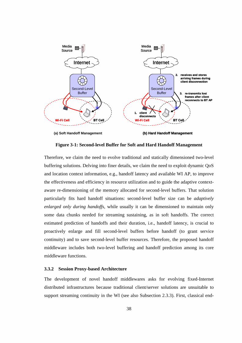
38
Internet
MediaSource
Second-LevelBuffer
Wi-Fi Cell BT Cell
InternetInternet
MediaSource
Second-LevelBuffer
Second-LevelBuffer
Wi-Fi Cell BT Cell
(a) Soft Handoff Management
Internet
MediaSource
Second-LevelBuffer
Wi-Fi Cell BT Cell
1. clientdisconnects
2. receives and storesarriving frames during client disconnection
3. re-transmits lostframes after client reconnects to BT AP
(b) Hard Handoff Management
InternetInternet
MediaSource
Second-LevelBuffer
Second-LevelBuffer
Wi-Fi Cell BT Cell
1. clientdisconnects
2. receives and storesarriving frames during client disconnection
3. re-transmits lostframes after client reconnects to BT AP
(b) Hard Handoff Management
Figure 3-1: Second-level Buffer for Soft and Hard Handoff Management
Therefore, we claim the need to evolve traditional and statically dimensioned two-level
buffering solutions. Delving into finer details, we claim the need to exploit dynamic QoS
and location context information, e.g., handoff latency and available WI AP, to improve
the effectiveness and efficiency in resource utilization and to guide the adaptive context-
aware re-dimensioning of the memory allocated for second-level buffers. That solution
particularly fits hard handoff situations: second-level buffer size can be adaptively
enlarged only during handoffs, while usually it can be dimensioned to maintain only
some data chunks needed for streaming sustaining, as in soft handoffs. The correct
estimated prediction of handoffs and their duration, i.e., handoff latency, is crucial to
proactively enlarge and fill second-level buffers before handoff (to grant service
continuity) and to save second-level buffer resources. Therefore, the proposed handoff
middleware includes both two-level buffering and handoff prediction among its core
middleware functions.
3.3.2 Session Proxy-based Architecture
The development of novel handoff middlewares asks for evolving fixed-Internet
distributed infrastructures because traditional client/server solutions are unsuitable to
support streaming continuity in the WI (see also Subsection 2.3.3). First, classical end-
39
to-end mechanisms for flow and congestion control are not effective over wireless links;
in particular, they cannot identify possible handoff situations that occur in the last wired-
wireless hop. Second, the round-trip time between client and server limits the
applicability and the frequency of all those management actions that require prompt
intervention in the case of local wireless link changes, such as for data re-transmissions
during hard handoffs. Finally, as introduced in the previous section, we adopt two-level
buffering architectures; in order to maintain second-level buffers it is necessary to enable
buffering management functions in the last wired-wireless hop.
For all the above reasons, we propose distributed handoff management organized by
middleware proxies working along the service path between client and server. First and
foremost, we claim that only management operations executed in client locality can
guarantee service continuity by promptly foreseeing and reacting to client handoffs.
Middlewares should provide client devices with companion middleware proxies —
Session Proxies — that execute in the client current WI access network by acting
autonomously on client behalf. A Session Proxy should be designed: i) to exploit context
awareness for the transparent and proactive execution of adaptation and reconfiguration
operations required by its client movements/WI handoffs; ii) to manage session state
(second-level – proxy or proxy-side – buffers, service binding information, …) of all
continuous services currently accessed by its client device; and iii) to operate
asynchronously especially while its client gets disconnected during handoffs.
In addition, Session Proxies should be mobile to autonomously follow their roaming
clients at provision time, to contribute to the automatic deployment of handoff
management intelligence, and to re-distribute the service provisioning load within
network access localities. In particular, session proxies can predict client handoff in
advance and migrate to follow client movements, by exploiting pre-fetched data to
sustain streaming until the completion of needed flow re-directions.
Let us note that the traditional Internet is already crowded by many kinds of proxies
(for caching, authentication, re-directing duties and more). Anyway, the introduction of
proxies to split direct client-to-server connections in locations close to the wireless
clients represents an effective solution to reduce signaling traffic on service paths and to
personalize service delivery [3], [5], [29], [49], [10].
40
3.4 The MUM Architecture
This section describes MUM (Mobile agent-based Ubiquitous multimedia Middleware),
a context-aware middleware aimed to support service continuity. MUM intends to
simplify user development and deployment of continuous services by only requiring the
service layer to declare service requirements and to obtain service continuity by
exploiting session proxies, deployed in the last hop of server-to-client path [10], [15]. To
achieve these goals, MUM smoothes handoff effects via application-level management
operations with full awareness of handoff context.
MUM is proactive: it dynamically monitors the quality of signal at all the wireless
network interfaces available at client and predicts possible handoff occurrences to
anticipate handoff management. MUM exploits awareness of handoff behaviors of
wireless cards/drivers to properly interpret monitored RSSI data, by employing an
original prediction technique that obtains effective horizontal and vertical handoff
predictions for different and heterogeneous underlying wireless technology and vendors.
MUM is adaptive: it chooses among different forms of QoS-aware handoff
management and selects WI-multimedia-specific protocols to minimize network
overhead and resource consumption at client/proxy nodes adaptively. With a closer view
to details, MUM is able to adapt and massage requested multimedia flows depending on
static mobile device and network profiles and on more dynamically monitored network
QoS conditions; moreover, MUM supports both soft and hard handoff management so to
fully exploit all mobile client capabilities.
MUM is re-configurable: it exploits awareness of client movements and of
micro/macro/global handoffs to support dynamic re-bind. In particular, MUM includes
fast client re-addressing functions and context transfer to proactively update all endpoint
information at client and target session proxies, so to accelerate client-to-proxy re-bind.
The following two subsections present the distributed MUM architecture and
introduce all main MUM mechanisms and facilities.
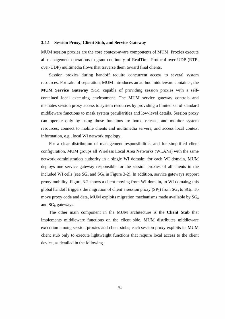
41
3.4.1 Session Proxy, Client Stub, and Service Gateway
MUM session proxies are the core context-aware components of MUM. Proxies execute
all management operations to grant continuity of RealTime Protocol over UDP (RTP-
over-UDP) multimedia flows that traverse them toward final clients.
Session proxies during handoff require concurrent access to several system
resources. For sake of separation, MUM introduces an ad hoc middleware container, the
MUM Service Gateway (SG), capable of providing session proxies with a self-
contained local executing environment. The MUM service gateway controls and
mediates session proxy access to system resources by providing a limited set of standard
middleware functions to mask system peculiarities and low-level details. Session proxy
can operate only by using those functions to: book, release, and monitor system
resources; connect to mobile clients and multimedia servers; and access local context
information, e.g., local WI network topology.
For a clear distribution of management responsibilities and for simplified client
configuration, MUM groups all Wireless Local Area Networks (WLANs) with the same
network administration authority in a single WI domain; for each WI domain, MUM
deploys one service gateway responsible for the session proxies of all clients in the
included WI cells (see SGa and SGb in Figure 3-2). In addition, service gateways support
proxy mobility. Figure 3-2 shows a client moving from WI domaina to WI domainb; this
global handoff triggers the migration of client’s session proxy (SP2) from SGa to SGb. To
move proxy code and data, MUM exploits migration mechanisms made available by SGa
and SGb gateways.
The other main component in the MUM architecture is the Client Stub that
implements middleware functions on the client side. MUM distributes middleware
execution among session proxies and client stubs; each session proxy exploits its MUM
client stub only to execute lightweight functions that require local access to the client
device, as detailed in the following.
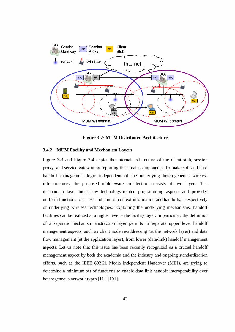
42
ServiceGateway
InternetBT AP Wi-Fi AP
MUM WI domaina MUM WI domainb
SP1
SessionProxy
SP CSClientStub
SP2 SP2 SP3
CS1
CS2CS2
CS3
SGa
SG
SGb
ServiceGateway
InternetBT AP Wi-Fi AP
MUM WI domaina MUM WI domainb
SP1
SessionProxy
SPSessionProxy
SP CSClientStub
SP2 SP2 SP3
CS1
CS2CS2
CS3
SGa
SGSG
SGb
Figure 3-2: MUM Distributed Architecture
3.4.2 MUM Facility and Mechanism Layers
Figure 3-3 and Figure 3-4 depict the internal architecture of the client stub, session
proxy, and service gateway by reporting their main components. To make soft and hard
handoff management logic independent of the underlying heterogeneous wireless
infrastructures, the proposed middleware architecture consists of two layers. The
mechanism layer hides low technology-related programming aspects and provides
uniform functions to access and control context information and handoffs, irrespectively
of underlying wireless technologies. Exploiting the underlying mechanisms, handoff
facilities can be realized at a higher level – the facility layer. In particular, the definition
of a separate mechanism abstraction layer permits to separate upper level handoff
management aspects, such as client node re-addressing (at the network layer) and data
flow management (at the application layer), from lower (data-link) handoff management
aspects. Let us note that this issue has been recently recognized as a crucial handoff
management aspect by both the academia and the industry and ongoing standardization
efforts, such as the IEEE 802.21 Media Independent Handover (MIH), are trying to
determine a minimum set of functions to enable data-link handoff interoperability over
heterogeneous network types [11], [101].
43
Service Level
Bluetooth Data-linkHandoff Manager
BluetoothConnectivity
Cellular Data-linkHandoff Manager
CellularConnectivity
MUM Client Interface
Client Stub Mechanism Layer
Client Stub Facility Layer
Handoff Prediction Monitor
RSSI Filtering andComparison
Prediction Event Construction and
Notification
Service Continuity Manager (Client-side)
Handoff Execution andBuffer Management
DataTx./Rx.
Fast Service Re-binder(Client-side)
FastRe-Addressing
SessionControl
Functions
ComponentRe-bind
IEEE 802.11x Data-linkHandoff Manager
IEEE 802.11xConnectivity
Wi-Fi QoS AnomalyMonitoring
Service Level
Bluetooth Data-linkHandoff Manager
BluetoothConnectivity
Bluetooth Data-linkHandoff Manager
BluetoothConnectivity
Cellular Data-linkHandoff Manager
CellularConnectivity
Cellular Data-linkHandoff Manager
CellularConnectivity
MUM Client Interface
Client Stub Mechanism Layer
Client Stub Facility Layer
Handoff Prediction Monitor
RSSI Filtering andComparison
Prediction Event Construction and
Notification
Handoff Prediction Monitor
RSSI Filtering andComparison
Prediction Event Construction and
Notification
RSSI Filtering andComparison
Prediction Event Construction and
Notification
Service Continuity Manager (Client-side)
Handoff Execution andBuffer Management
DataTx./Rx.
Service Continuity Manager (Client-side)
Handoff Execution andBuffer Management
DataTx./Rx.
Handoff Execution andBuffer Management
DataTx./Rx.
Fast Service Re-binder(Client-side)
FastRe-Addressing
SessionControl
Functions
ComponentRe-bind
Fast Service Re-binder(Client-side)
FastRe-Addressing
SessionControl
Functions
ComponentRe-bind
FastRe-Addressing
SessionControl
Functions
ComponentRe-bind
IEEE 802.11x Data-linkHandoff Manager
IEEE 802.11xConnectivity
Wi-Fi QoS AnomalyMonitoring
IEEE 802.11x Data-linkHandoff Manager
IEEE 802.11xConnectivity
Wi-Fi QoS AnomalyMonitoring
IEEE 802.11xConnectivity
Wi-Fi QoS AnomalyMonitoring
Figure 3-3: Client-Stub Internal Architecture
At the facility layer, the core handoff management facilities are as follows. The
Handoff Prediction Monitor (HPM), deployed at the client stub, is responsible of
proactive handoff initiation; in particular, it exploits mechanism layer components to
monitor local wireless coverage situation and to calculate horizontal/vertical handoff
prediction events. The Handoff Decision Manager (HDM), deployed at the session
proxy, receives handoff prediction events, gathers necessary context information from
service gateway context information store, e.g., network topology, and uses those
information, along with SLS and client profile information, to decide handoff
management strategy (soft/hard), and to dimension second-level buffers. SLS and client
(user/device) profile can be explicitly specified by the service at the client side, by
means of the MUM Client Interface (MCI). The Service Continuity Manager (SCM),
deployed at both sides, coordinate and schedule multimedia data transmissions and
manages client-/proxy-side buffers so to grant continuous multimedia flow delivery.
Finally, the Fast Session Re-binder (FSR), deployed at both sides, implements handoff
protocols and session control functions necessary to enable fast client re-configuration
and service component re-bind necessary any time a client enters a new WI access
domain/network.
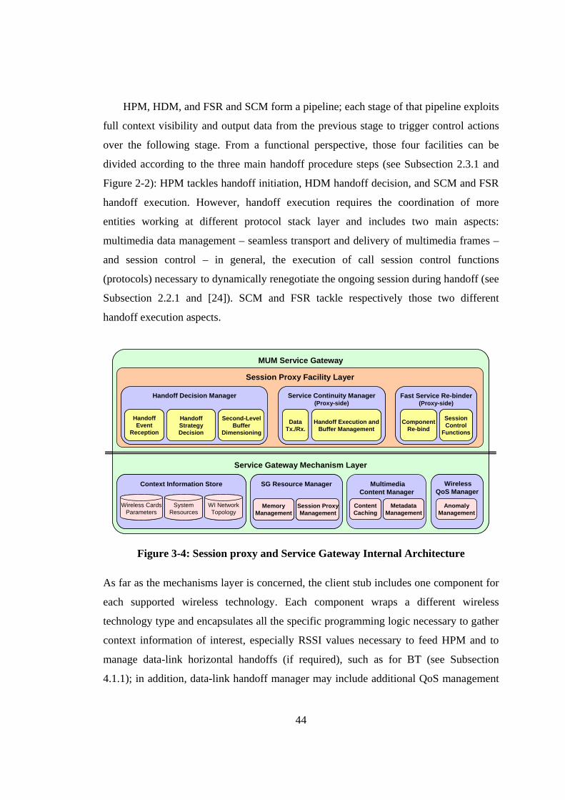
44
HPM, HDM, and FSR and SCM form a pipeline; each stage of that pipeline exploits
full context visibility and output data from the previous stage to trigger control actions
over the following stage. From a functional perspective, those four facilities can be
divided according to the three main handoff procedure steps (see Subsection 2.3.1 and
Figure 2-2): HPM tackles handoff initiation, HDM handoff decision, and SCM and FSR
handoff execution. However, handoff execution requires the coordination of more
entities working at different protocol stack layer and includes two main aspects:
multimedia data management – seamless transport and delivery of multimedia frames –
and session control – in general, the execution of call session control functions
(protocols) necessary to dynamically renegotiate the ongoing session during handoff (see
Subsection 2.2.1 and [24]). SCM and FSR tackle respectively those two different
handoff execution aspects.
MUM Service Gateway
Session Proxy Facility Layer
Context Information Store
SystemResources
WI NetworkTopology
Wireless CardsParameters
Service Gateway Mechanism Layer
Service Continuity Manager(Proxy-side)
Handoff Execution andBuffer Management
DataTx./Rx.
MultimediaContent Manager
ContentCaching
MetadataManagement
SG Resource Manager
MemoryManagement
Session ProxyManagement
Fast Service Re-binder(Proxy-side)
SessionControl
Functions
ComponentRe-bind
Handoff Decision Manager
HandoffEvent
Reception
HandoffStrategyDecision
Second-LevelBuffer
Dimensioning
WirelessQoS Manager
AnomalyManagement
MUM Service Gateway
Session Proxy Facility Layer
Context Information Store
SystemResources
WI NetworkTopology
Wireless CardsParameters
Context Information Store
SystemResources
WI NetworkTopology
Wireless CardsParameters
SystemResources
WI NetworkTopology
Wireless CardsParameters
Service Gateway Mechanism Layer
Service Continuity Manager(Proxy-side)
Handoff Execution andBuffer Management
DataTx./Rx.
Service Continuity Manager(Proxy-side)
Handoff Execution andBuffer Management
DataTx./Rx.
Handoff Execution andBuffer Management
DataTx./Rx.
MultimediaContent Manager
ContentCaching
MetadataManagement
ContentCaching
MetadataManagement
SG Resource Manager
MemoryManagement
Session ProxyManagement
SG Resource Manager
MemoryManagement
Session ProxyManagement
MemoryManagement
Session ProxyManagement
Fast Service Re-binder(Proxy-side)
SessionControl
Functions
ComponentRe-bind
Fast Service Re-binder(Proxy-side)
SessionControl
Functions
ComponentRe-bind
SessionControl
Functions
ComponentRe-bind
Handoff Decision Manager
HandoffEvent
Reception
HandoffStrategyDecision
Second-LevelBuffer
Dimensioning
Handoff Decision Manager
HandoffEvent
Reception
HandoffStrategyDecision
Second-LevelBuffer
Dimensioning
HandoffEvent
Reception
HandoffStrategyDecision
Second-LevelBuffer
Dimensioning
WirelessQoS Manager
AnomalyManagement
WirelessQoS Manager
AnomalyManagement
Figure 3-4: Session proxy and Service Gateway Internal Architecture
As far as the mechanisms layer is concerned, the client stub includes one component for
each supported wireless technology. Each component wraps a different wireless
technology type and encapsulates all the specific programming logic necessary to gather
context information of interest, especially RSSI values necessary to feed HPM and to
manage data-link horizontal handoffs (if required), such as for BT (see Subsection
4.1.1); in addition, data-link handoff manager may include additional QoS management
45
logic necessary to overcome technology-specific issues/problems, such as for the Wi-Fi
anomaly (see Subsection 2.1.3 and 5.2.2). By delving into finer details, in order to
enable the widest possible interoperability, e.g., to interoperate with all those
technologies that exclude direct application level control of data-link horizontal handoff
process (such as Wi-Fi, see Section 4.1.2), our architecture completely demands data-
link horizontal handoff management to the mechanism layer. Of course, vertical
handoffs, involving two or more different wireless technologies, are handled by the
facility layer.
While session proxy and client stub include handoff-specific facilities, proxy-side
mechanisms include service gateway components needed to enable session proxy
execution and to tackle other wireless impairments not strictly or directly related to
handoff management; in addition, they comprise more generic mechanisms for
multimedia content provisioning over the traditional Internet. Context information store
describes the local WI domain and includes all information necessary to enable context-
aware handoff management (see Subsection 3.1). Session Proxy Management supports
session proxy lifecycle, enables their mobility (code and data migration), and provides
necessary Application Programming Interfaces (API) needed by session proxy facilities,
e.g., to let SCM book and release memory resources necessary for second-level
buffering. Wireless QoS Manager addresses all those technology-specific wireless
impairments that are not directly related to handoff management, but that could
contribute to compromise mobile multimedia provisioning. Finally, Multimedia Content
Manager includes generic multimedia caching and adaptation mechanisms to
dynamically adapt delivered contents by selecting appropriate content trans-coders.
3.5 Chapter Conclusions and Implementation Chapters Overview
In this chapter we have introduced our full context-aware model for open and seamless
handoff management in the WI; then, by using such model, we derived main handoff
management requirement and design guidelines for the implementation of novel WI
handoff middleware architectures; finally, we introduced the MUM handoff middleware
by presenting its distributed architecture and its main facilities and mechanisms.
46
The next three chapters will provide implementation details and discussion about all
main facility and mechanism components outlined above. Component presentation (and
chapter organization) follows two main criteria: we distinguish MUM components
according to the three main handoff management directions pointed out by our context
awareness model – handoff, QoS, and location awareness; we also divide them
according to their respective roles within the whole handoff management process –
namely, handoff initiation, decision, and execution. Chapter 4 is focused more on
handoff initiation and decision – handoff awareness – and presents HPM (including also
Data-link Handoff Managers) and HDM components. Chapter 5 is dedicated to handoff
execution by focusing on the data management and seamless multimedia flow
provisioning – QoS awareness; in particular, it presents SCM, WI QoS Manager, and
Multimedia Content Manager. Finally, Chapter 6 is devoted to address handoff
execution, especially session control management – location awareness – and presents
FSR.
47
4. Handoff Prediction and Decision
In this chapter we will describe the MUM support for handoff prediction and decision.
The two main guidelines of this part of the middleware are the proactive initiation of the
handoff management process and the decision of all necessary handoff management
operations necessary to guarantee session continuity.
Proactive handoff initiation is achieved by monitoring the behavior of all wireless
interfaces available on the mobile device and by notifying handoff prediction events
from the client stub to the session proxy. The proposed handoff initiation method can
evaluate both horizontal and vertical handoff prediction events by only requiring access
to RSSI values for all WI APs in client visibility. Interoperability and portability – with
different wireless technologies, operating systems and wireless card models/drivers – is
enabled by client stub mechanism components that isolate the facility layer from data-
link handoff management and specific wireless network programming details.
Handoff prediction events trigger handoff decision that is executed by the session
proxy. The main goal of handoff decision is guaranteeing session continuity. Handoff
decision process consists of two main steps: first, it chooses the handoff management
strategy – soft or hard – and target wireless technology; then, it dynamically tunes
second-level buffer dimension according to the current provisioning conditions and to
the SLS specified by the application layer.
A clear comprehension of the data-link handoff manager characteristics is essential to
understand proactive handoff initiation functionalities, so we will start this chapter by
describing the BT and Wi-Fi Data-link Handoff Managers. Hence, we will focus on
proactive handoff initiation: we will present HPM internal architecture and we will give
implementation insights about adopted prediction method RSSI-Grey Model (RSSI-GM)
[14], [37]. Finally, we will discuss the HDM and its interaction with the SG Resource
Manager – especially with the SG Memory Manager. In particular, we will first describe
HDM internal architecture – mainly the Handoff Strategy Decision and the Second-level
Buffer Dimensioning components – and we will give implementation insights about
applied decision and dimensioning algorithms by showing how simple SLSs (introduced
by MUM) enable transparent handoff decision at the middleware level (see also
Subsection 2.2.3). Then, we will describe how MUM – through SG Memory Manager –
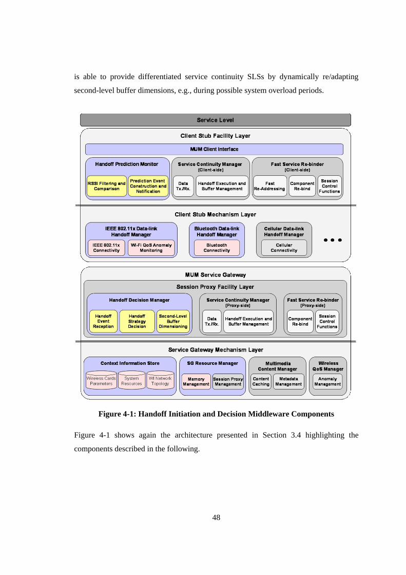
48
is able to provide differentiated service continuity SLSs by dynamically re/adapting
second-level buffer dimensions, e.g., during possible system overload periods.
Figure 4-1: Handoff Initiation and Decision Middleware Components
Figure 4-1 shows again the architecture presented in Section 3.4 highlighting the
components described in the following.
49
4.1 Data-link Handoff Managers
Data-link handoff managers have been designed according to the following two basic
requirements: i) to provide a set of API compliant with a common interface; ii) to hide
data-link horizontal handoff details. Both requirements are needed to let the facility layer
be independent from low level details.
According to the first requirement, the set of API should provide at least three
crucial information items: raw RSSI values, internal RSSI values estimates, and
expected data-link handoff latency. In fact, in order to evaluate handoff predictions,
HPM must gather, for all available wireless technologies, RSSI values of all APs in
client visibility. However, different wireless technologies employ heterogeneous RSSI
scales (linear, logarithmic, ...) and ranges for RSSI values. To permit RSSI comparison,
MUM defines a fixed number of internal RSSI ranges and each data-link handoff
manager has to map raw RSSI values read on its wireless cards to internal RSSI ranges;
as shown in Subsection 4.2.2, we experimentally found that choosing to have only five
ranges (very-low, low, medium, high, very-high) is a sufficient coarse grain to obtain
good prediction performance results. In addition, data-link managers hide all the
programming complexities necessary to gather RSSI data. In fact, while traditional
fixed-network programming is based on only one standard API, i.e., the Berkeley
sockets, advanced wireless network programming libraries introduce novel API and
different RSSI gathering modes, depending on the peculiarities of each wireless
technology. Finally, each data-link manager has to provide data-link handoff latency;
that information is crucial to dimension second-level buffers (see Subsection 3.3.1).
Hence, each data-link manager has to implement the three following interfaces:
• int getRawRSSI() to directly extract card-provided RSSI values;
• int getInternalRSSI() to gather the corresponding internal RSSI range;
• getDatalinkHandoffDuration() to obtain data-link handoff latency.
For the second requirement, each manager encapsulates all the control logic to
autonomously complete data-link handoffs so to separate all low level data-link handoff
management complexities from upper level handoff management aspects, i.e., session
continuity management.
50
By focusing on supported wireless technologies, MUM supports several wireless
technologies, but especially it serves BT and Wi-Fi that represent today the two most
widespread wireless technologies. The next two subsections give more implementation
insights about BT and Wi-Fi data-link handoff managers.
4.1.1 BT Data-link Handoff Manager
BT Data-link Handoff Manager implements data-link handoff manager API. In
particular, as anticipated in Subsection 2.1.1, the BT SIG has neither defined nor
standardized handoff management mechanisms for BT; hence, BT manager has also to
transparently provide a handoff management solution for horizontal handoff in BT.
By focusing on RSSI gathering and conversion to internal RSSI values, BT
specification gives some implementation guidelines for the definition of BT RSSI
values; it defines the Golden Receive Power Range (GRPR) that divides RSSI values
into three main regions: a RSSI value close to 0 indicates good BT network coverage,
with a high goodput and low link error rates, a value greater than 0 for optimal network
coverage – usually achieved only in a very limited area in the vicinity of the BT AP –,
and a negative value (less that 0) for a bad network coverage [20]. As we verified with
our experiments (see Subsection 4.2.2), current BT devices are usually compliant with
the above specification, thus simplifying the mapping between the raw read RSSI value
and MUM internal RSSI values.
With respect to data-link horizontal handoff management, BT manager implements
horizontal data-link handoff management by performing the following operations: it
creates/destroys BT connections and it searches for APs (via inquiry/scan procedures
and service discovery searches). The initiation and decision phases are performed
adopting the Last Second Soft Handoff (LSSH) scheme, introduced in [34]. For data-link
handoff decision, the BT manager adopts a soft handoff scheme and establishes multiple
connections. To reduce the number of APs to monitor during the decision, a topology-
based solution is adopted; in particular, the BT manager is initially configured (by the
session proxy) with the local BT network topology (stored by the WI Network Topology
store, see Figure 3-4) and exploits BT network infrastructure configuration to choose the
next AP to use among neighbor APs.
51
BT data-link handoff latencies depend mainly on the above data-link handoff
procedure and on perceived wireless signal power, i.e., BT coverage; while they are
rather independent on the specific BT wireless card model, as demonstrated by collected
experimental results (see Table 4-1). By delving into finer details, the decision phase
sequentially scans all neighboring APs and selects the AP with the best current RSSI
value; the sequential scan presents the drawback of leading to quite long decision times,
and hence to long horizontal handoff latencies (up to 3,7s with bad network conditions).
MUM evaluates those data-link handoff latency values with a preliminarily
configuration phase and stores them at the Wireless Cards Parameters store (see Figure
3-4); session proxies employ those parameters for the initial client stub configuration.
BT data-link handoff manager implementation is based on the BlueZ stack for
Linux clients and on the aveLink stack for Windows clients [100], [102]. The BT
manager has been integrated into MUM within the framework of a joint research work
[11]. The interested reader may find further details about the LSSH scheme in [34].
4.1.2 Wi-Fi Data-link Handoff Manager
Also the Wi-Fi Data-link Handoff Manager implements data-link handoff manager API;
however, since the IEEE 802.11 standard specifies the mechanisms to implement the
handoff procedure (see Subsection 2.1.1), Wi-Fi manager can demand horizontal
handoff management to data-link drivers.
With regard to RSSI data gathering and conversion, Wi-Fi specification (differently
from the BT one) does not give any implementation guideline about RSSI value; hence
diverse wireless cards/drivers implementations of the same wireless standard employ
heterogeneous RSSI scales (linear, logarithmic, ...) and ranges for RSSI values, e.g., the
RSSI of an Orinoco Gold Wi-Fi card varies in the range [-130, -10], while the one of a
Cisco Wi-Fi card in the range [0, 100]. That high diversity motivates our middleware
approach to hide vendor-specific differences so to provide not only raw RSSI values
directly read from the wireless card, but also MUM internal RSSI ranges.
By focusing on data-link handoff management, the IEEE 802.11 standard leaves
unspecified the handoff operation combination and durations and recent research works
have demonstrated that handoff duration is highly influenced by several factors such as
52
client cards, AP models, and especially actual network coverage, and can vary from
some hundreds of ms to even 2s [67]. Some IEEE 802.11 enhancements have been
recently proposed both from academia and IEEE 802.11 standardization committees to
enhance actual handoff procedures, thus guaranteeing an upper bound for handoff
latencies, e.g., IEEE 802.11r [99]. Nonetheless, those extensions are still not available in
most diffused APs and would require firmware upgrade or re-deployment of all old Wi-
Fi equipment. Hence, in order to estimate data-link handoff latency, we execute a
preliminary data-link manager configuration phase that evaluates handoff latency with
different wireless cards and under different network coverage situations. For each
profiled wireless card, MUM stores evaluated handoff latencies at the at the Wireless
Cards Parameters store (see Figure 2-1). Session proxies employ those parameters for
the initial client stub configuration for specific wireless card models; thereafter, data-link
handoff manager uses them to return to the facility layer expected handoff latency time
depending on actual network coverage measured at client.
Finally, the Wi-Fi Data-link Handoff Manager hosts the Wi-Fi QoS Anomaly
Monitoring component to enable QoS management countermeasures to the Wi-Fi
anomaly; a thorough description of this component and its role will be given the
following chapter along with the presentation of all other QoS-related management and
execution aspects (see Subsection 5.2).
Wi-Fi data-link handoff manager implementation is based on the standard Network
Driver Interface Specification (NDIS) – and its Java-based interface, the Java Wireless
Research API (JWRAPI) – for Windows clients and the Wireless Extensions –
especially the iwconfig tool – for Linux nodes [58], [91].
4.2 Handoff Prediction
This section presents HPM architecture and implementation insights about the proposed
RSSI-GM predictor; then, it reports a wide set of experimental results that have been
collected to assess effectiveness and efficiency of HPM predictions.
53
4.2.1 Handoff Prediction Monitor
HPM evaluates handoff prediction. It periodically gathers RSSI data, calculates handoff
predictions with our lightweight RSSI-GM predictor, then it constructs and pushes
prediction events to the session proxy, i.e., to the HDM. Any prediction event includes
the following attributes: handoff type (horizontal/vertical), predicted target AP (wireless
technology and MAC address), data-link handoff latency, and prediction time-advance,
i.e., time between handoff prediction and occurrence.
For horizontal handoff, HPM foresees both the next handoff execution and client
leaving of wireless-enabled area for each wireless interface active at client node. For
vertical handoff, HPM considers one wireless interface as the default one and emits a
vertical handoff prediction event whenever it foresees that another wireless interface has
stronger RSSI than the default one. The decision of default wireless interface, together
with other handoff decisions, is responsibility of HDM (see Subsection 4.3.1).
To perform handoff predictions, RSSI-GM predictor gathers RSSI values by using
the data-link manager API (by using card-provided RSSI values when one only wireless
interface is active and internal RSSI values otherwise) and executes a very lightweight
procedure that requires filtering, comparing, and predicting future RSSIs. The RSSI-GM
predictor executes two main steps: i) RSSI filtering to mitigate RSSI fluctuations due to
signal noise; and ii) prediction evaluation to estimate prediction time-advance.
RSSI filtering (the first step) employs a first-order Grey-based discrete model (see
the next subsection for more technical details) that, for each visible AP, calculates
filtered RSSI values on the basis of a finite series of N RSSI values monitored in the
recent past [37]. This filtering technique imposes very limited overhead at the client
node while filtered RSSI depends on N; the greater N, the more regular the RSSI filtered
values, the slower the filtered RSSI sequence follows the possibly abrupt time evolution
of actual RSSI.
Prediction evaluation (the second step) works on filtered RSSI values. For each
interface, it selects the RSSI — RSSIo — of the old AP, and the strongest RSSI — RSSIt
— that is considered as target AP RSSI. Then, RSSI-GM predictor checks if it is
necessary to emit a handoff prediction event by adopting two prediction models
designed to differentiate prediction evaluation depending on the data-link handoff
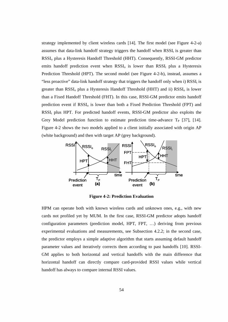
54
strategy implemented by client wireless cards [14]. The first model (see Figure 4-2-a)
assumes that data-link handoff strategy triggers the handoff when RSSIt is greater than
RSSIo plus a Hysteresis Handoff Threshold (HHT). Consequently, RSSI-GM predictor
emits handoff prediction event when RSSIo is lower than RSSIt plus a Hysteresis
Prediction Threshold (HPT). The second model (see Figure 4-2-b), instead, assumes a
“less proactive” data-link handoff strategy that triggers the handoff only when i) RSSIt is
greater than RSSIo plus a Hysteresis Handoff Threshold (HHT) and ii) RSSIo is lower
than a Fixed Handoff Threshold (FHT). In this case, RSSI-GM predictor emits handoff
prediction event if RSSIo is lower than both a Fixed Prediction Threshold (FPT) and
RSSIt plus HPT. For predicted handoff events, RSSI-GM predictor also exploits the
Grey Model prediction function to estimate prediction time-advance TP [37], [14].
Figure 4-2 shows the two models applied to a client initially associated with origin AP
(white background) and then with target AP (grey background).
RSSIo
HHTHPT
TP
time
RSSI
HHTHPT
time
RSSI
FHT
FPT
TP
RSSItRSSIo RSSIt
Predictionevent(a) (b)
Predictionevent
RSSIo
HHTHPT
TP
time
RSSI
HHTHPT
time
RSSI
FHT
FPT
TP
RSSItRSSIo RSSIt
Predictionevent(a) (b)
Predictionevent
Figure 4-2: Prediction Evaluation
HPM can operate both with known wireless cards and unknown ones, e.g., with new
cards not profiled yet by MUM. In the first case, RSSI-GM predictor adopts handoff
configuration parameters (prediction model, HPT, FPT, …) deriving from previous
experimental evaluations and measurements, see Subsection 4.2.2; in the second case,
the predictor employs a simple adaptive algorithm that starts assuming default handoff
parameter values and iteratively corrects them according to past handoffs [10]. RSSI-
GM applies to both horizontal and vertical handoffs with the main difference that
horizontal handoff can directly compare card-provided RSSI values while vertical
handoff has always to compare internal RSSI values.
55
To estimate horizontal data-link handoff latency, HPM obtains data-link handoff
latency from the mechanism layer. By focusing on vertical data-link handoff latencies,
as demonstrated by several experiments that we preliminarily conduced, data-link
vertical handoff latencies correspond to the horizontal data-link handoff latencies
obtained for the target wireless card. Hence, for vertical data-link handoff latency
estimation, HPM uses horizontal data-link handoff latency obtained by the data-link
manager corresponding to the target wireless card. HPM uses those estimations to
complete prediction event construction, i.e., to attach data-link handoff latency to the
prediction event, then it notifies obtained prediction event to HDM.
By focusing on HPM tuning, a preliminary MUM configuration phase is necessary
to evaluate also the handoff configuration parameters used to feed the prediction model.
For each profiled wireless card, MUM stores evaluated configuration parameters, along
with horizontal data-link handoff latencies (see Subsections 4.1.1 and 4.1.2) at the
Wireless Cards Parameters store (see Figure 3-4). Session proxies employ those
parameters for the initial configuration of RSSI-GM for specific wireless card models.
4.2.2 Experimental Results
We have thoroughly tested and evaluated the performance of MUM handoff prediction
by deploying HPM on several WI clients moving in our campus wireless network. Our
testbed consists of several Windows and Linux client laptops equipped with four
different wireless cards: i) internal Intel PRO/Wireless 3945AGB, ii) Orinoco Gold Wi-
Fi cards, iii) internal ASUS BT card, and iv) Mopogo BT dongles. During experiments,
clients have randomly moved with variable speed between 0,6m/s and 1,5m/s between
BT and Wi-Fi cells served respectively by Mopogo BT dongles and Cisco Aironet 1100
APs.
The reported experimental results point out two different and crucial aspects of our
proposal: the first one introduces preliminary configuration results collected to
determine horizontal data-link handoff latencies (see Table 4-1); the second one (see
Table 4-2 and Table 4-3) proves how wireless card model awareness permits to obtain
good horizontal/vertical handoff predictions.
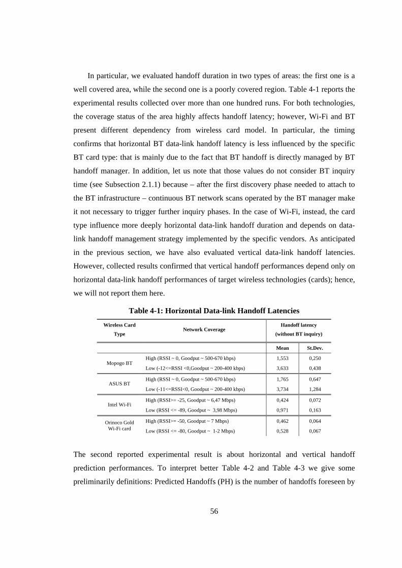
56
In particular, we evaluated handoff duration in two types of areas: the first one is a
well covered area, while the second one is a poorly covered region. Table 4-1 reports the
experimental results collected over more than one hundred runs. For both technologies,
the coverage status of the area highly affects handoff latency; however, Wi-Fi and BT
present different dependency from wireless card model. In particular, the timing
confirms that horizontal BT data-link handoff latency is less influenced by the specific
BT card type: that is mainly due to the fact that BT handoff is directly managed by BT
handoff manager. In addition, let us note that those values do not consider BT inquiry
time (see Subsection 2.1.1) because – after the first discovery phase needed to attach to
the BT infrastructure – continuous BT network scans operated by the BT manager make
it not necessary to trigger further inquiry phases. In the case of Wi-Fi, instead, the card
type influence more deeply horizontal data-link handoff duration and depends on data-
link handoff management strategy implemented by the specific vendors. As anticipated
in the previous section, we have also evaluated vertical data-link handoff latencies.
However, collected results confirmed that vertical handoff performances depend only on
horizontal data-link handoff performances of target wireless technologies (cards); hence,
we will not report them here.
Table 4-1: Horizontal Data-link Handoff Latencies
Wireless Card
Type Network Coverage
Handoff latency
(without BT inquiry)
Mean St.Dev.
High (RSSI ~ 0, Goodput ~ 500-670 kbps) 1,553 0,250 Mopogo BT
Low (-12<=RSSI <0,Goodput ~ 200-400 kbps) 3,633 0,438 High (RSSI ~ 0, Goodput ~ 500-670 kbps) 1,765 0,647
ASUS BT Low (-11<=RSSI<0, Goodput ~ 200-400 kbps) 3,734 1,284
High (RSSI>= -25, Goodput ~ 6,47 Mbps) 0,424 0,072 Intel Wi-Fi
Low (RSSI <= -89, Goodput ~ 3,98 Mbps) 0,971 0,163
High (RSSI>= -50, Goodput ~ 7 Mbps) 0,462 0,064 Orinoco Gold Wi-Fi card Low (RSSI <= -80, Goodput ~ 1-2 Mbps) 0,528 0,067
The second reported experimental result is about horizontal and vertical handoff
prediction performances. To interpret better Table 4-2 and Table 4-3 we give some
preliminarily definitions: Predicted Handoffs (PH) is the number of handoffs foreseen by
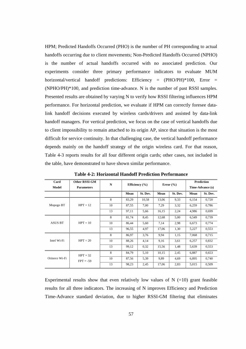
57
HPM; Predicted Handoffs Occurred (PHO) is the number of PH corresponding to actual
handoffs occurring due to client movements; Non-Predicted Handoffs Occurred (NPHO)
is the number of actual handoffs occurred with no associated prediction. Our
experiments consider three primary performance indicators to evaluate MUM
horizontal/vertical handoff predictions: Efficiency = (PHO/PH)*100, Error =
(NPHO/PH)*100, and prediction time-advance. N is the number of past RSSI samples.
Presented results are obtained by varying N to verify how RSSI filtering influences HPM
performance. For horizontal prediction, we evaluate if HPM can correctly foresee data-
link handoff decisions executed by wireless cards/drivers and assisted by data-link
handoff managers. For vertical prediction, we focus on the case of vertical handoffs due
to client impossibility to remain attached to its origin AP, since that situation is the most
difficult for service continuity. In that challenging case, the vertical handoff performance
depends mainly on the handoff strategy of the origin wireless card. For that reason,
Table 4-3 reports results for all four different origin cards; other cases, not included in
the table, have demonstrated to have shown similar performance.
Table 4-2: Horizontal Handoff Prediction Performance Card
Model
Other RSSI-GM
Parameters N Efficiency (%) Error (%)
Prediction
Time-Advance (s)
Mean St. Dev. Mean St. Dev. Mean St. Dev.
8 83,29 10,58 13,06 9,33 6,154 0,720
10 87,55 7,00 7,29 3,32 6,259 0,786 Mopogo BT HPT = 12
13 97,11 5,66 16,15 2,24 4,986 0,699
8 81,74 8,45 12,68 5,00 6,549 0,739
10 86,44 5,60 7,14 2,98 6,673 0,774 ASUS BT HPT = 10
13 96,55 4,97 17,06 1,30 5,227 0,553
8 86,97 3,76 9,94 1,15 7,068 0,715
10 88,26 4,14 9,16 3,61 6,257 0,832 Intel Wi-Fi HPT = 20
13 99,12 0,32 15,56 1,48 5,639 0,553
8 84,79 5,10 10,15 2,45 6,887 0,653
10 87,56 5,39 9,89 4,69 6,895 0,740 Orinoco Wi-Fi HPT = 32
FPT = -59 13 98,23 2,45 17,06 2,83 5,015 0,509
Experimental results show that even relatively low values of N (=10) grant feasible
results for all three indicators. The increasing of N improves Efficiency and Prediction
Time-Advance standard deviation, due to higher RSSI-GM filtering that eliminates
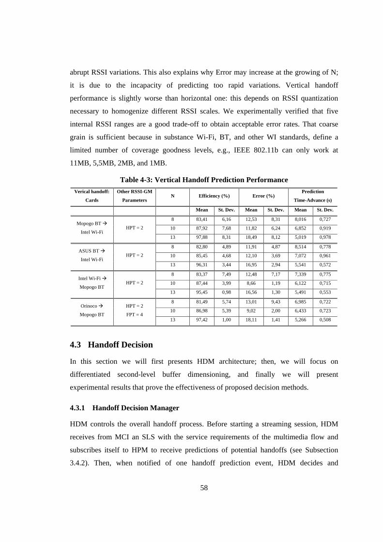
58
abrupt RSSI variations. This also explains why Error may increase at the growing of N;
it is due to the incapacity of predicting too rapid variations. Vertical handoff
performance is slightly worse than horizontal one: this depends on RSSI quantization
necessary to homogenize different RSSI scales. We experimentally verified that five
internal RSSI ranges are a good trade-off to obtain acceptable error rates. That coarse
grain is sufficient because in substance Wi-Fi, BT, and other WI standards, define a
limited number of coverage goodness levels, e.g., IEEE 802.11b can only work at
11MB, 5,5MB, 2MB, and 1MB.
Table 4-3: Vertical Handoff Prediction Performance Verical handoff:
Cards
Other RSSI-GM
Parameters N Efficiency (%) Error (%)
Prediction
Time-Advance (s)
Mean St. Dev. Mean St. Dev. Mean St. Dev.
8 83,41 6,16 12,53 8,31 8,016 0,727
10 87,92 7,68 11,82 6,24 6,852 0,919 Mopogo BT
Intel Wi-Fi HPT = 2
13 97,88 8,31 18,49 8,12 5,019 0,978
8 82,80 4,89 11,91 4,87 8,514 0,778
10 85,45 4,68 12,10 3,69 7,072 0,961 ASUS BT
Intel Wi-Fi HPT = 2
13 96,31 3,44 16,95 2,94 5,541 0,572
8 83,37 7,49 12,48 7,17 7,339 0,775
10 87,44 3,99 8,66 1,19 6,122 0,715 Intel Wi-Fi
Mopogo BT HPT = 2
13 95,45 0,98 16,56 1,30 5,491 0,553
8 81,49 5,74 13,01 9,43 6,985 0,722
10 86,98 5,39 9,02 2,00 6,433 0,723 Orinoco
Mopogo BT
HPT = 2
FPT = 4 13 97,42 1,00 18,11 1,41 5,266 0,508
4.3 Handoff Decision
In this section we will first presents HDM architecture; then, we will focus on
differentiated second-level buffer dimensioning, and finally we will present
experimental results that prove the effectiveness of proposed decision methods.
4.3.1 Handoff Decision Manager
HDM controls the overall handoff process. Before starting a streaming session, HDM
receives from MCI an SLS with the service requirements of the multimedia flow and
subscribes itself to HPM to receive predictions of potential handoffs (see Subsection
3.4.2). Then, when notified of one handoff prediction event, HDM decides and
59
dimensions the handoff management strategy – soft or hard – to apply, and initiates
handoff management operations by using SCM.
We propose a simple SLS that consists of four main parameters: service continuity
objective quality, tolerable delay, duration of the client-side buffer, and multimedia
stream description. In addition, as better detailed in the next subsection, MUM enables
differentiated session continuity provisioning and identifies three main classes of final
users, i.e., gold, silver, and copper quality; hence, we distinguish three main SLSs types
corresponding to above classes.
SLS parameters are as follows. The first one is a normalized parameter – varying
from 0 (best quality) to 1 (worst quality) – that indicates the objective quality – as
defined in [97] – that the service level is willing to receive for that multimedia flow
(during handoff). The parameter was intentionally chosen to be easy to specify by the
service level and independent of low-level QoS details, e.g., multimedia streaming
format, frame rate, and tolerable packet losses.
The second one is the maximum Tolerable Delay (TD) introduced by the handoff
middleware (due to the introduction of second level buffering). The service level can
specify either one or both the parameters. However, the joint optimization of those two
parameters is a complex task, especially for hard handoff management (see Subsection
3.3.1). In fact, hard handoff management smoothes handoff impairments through a
buffer-and-retransmit technique that bounds service continuity quality and tolerable
delay each other: the longer second-level buffered multimedia data chunk, the better
service continuity quality at the cost of higher frame delay (and vice versa).
The third one is the duration of Client-side Buffer (CB) that is decided and statically
allocated at the client node by the service level. In the following, we will assume that CB
duration will be long enough to cover the whole handoff latency in the more challenging
case of hard handoff management. That assumption is usually verified by full-fledged
laptop and by brand new PDAs and smart-phones. For very limited devices, however, it
is still possible to grant lossless handoff at the cost of higher resource consumption, as
we will discuss at the end of this subsection.
The fourth one describes the multimedia stream characteristics; in particular, we
focused mainly on video streams. For sake of clarity, we assume that there is only one
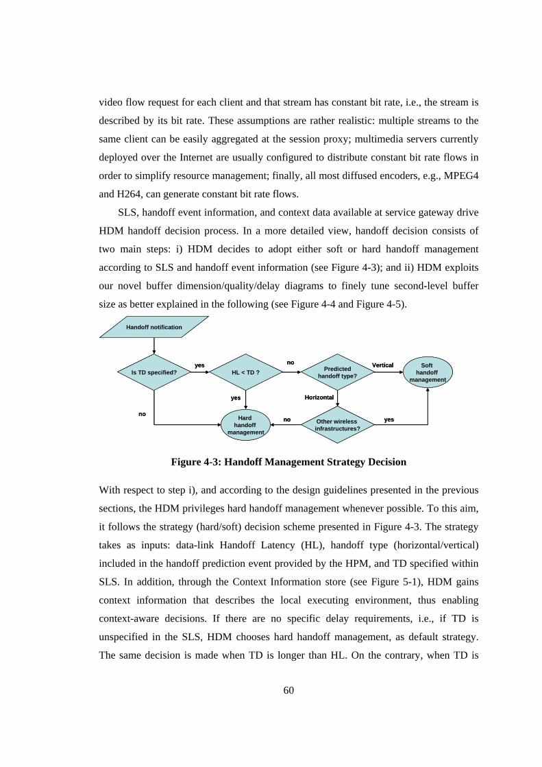
60
video flow request for each client and that stream has constant bit rate, i.e., the stream is
described by its bit rate. These assumptions are rather realistic: multiple streams to the
same client can be easily aggregated at the session proxy; multimedia servers currently
deployed over the Internet are usually configured to distribute constant bit rate flows in
order to simplify resource management; finally, all most diffused encoders, e.g., MPEG4
and H264, can generate constant bit rate flows.
SLS, handoff event information, and context data available at service gateway drive
HDM handoff decision process. In a more detailed view, handoff decision consists of
two main steps: i) HDM decides to adopt either soft or hard handoff management
according to SLS and handoff event information (see Figure 4-3); and ii) HDM exploits
our novel buffer dimension/quality/delay diagrams to finely tune second-level buffer
size as better explained in the following (see Figure 4-4 and Figure 4-5).
Handoff notification
yesHL < TD ?Is TD specified?
Soft handoff
management
yes
yesno
Horizontal
Predictedhandoff type?
Vertical
Other wireless infrastructures?
Hard handoff
management
no
no
Handoff notification
yesHL < TD ?Is TD specified?
Soft handoff
management
yes
yesno
Horizontal
Predictedhandoff type?
Vertical
Other wireless infrastructures?
Hard handoff
management
no
no
Figure 4-3: Handoff Management Strategy Decision
With respect to step i), and according to the design guidelines presented in the previous
sections, the HDM privileges hard handoff management whenever possible. To this aim,
it follows the strategy (hard/soft) decision scheme presented in Figure 4-3. The strategy
takes as inputs: data-link Handoff Latency (HL), handoff type (horizontal/vertical)
included in the handoff prediction event provided by the HPM, and TD specified within
SLS. In addition, through the Context Information store (see Figure 5-1), HDM gains
context information that describes the local executing environment, thus enabling
context-aware decisions. If there are no specific delay requirements, i.e., if TD is
unspecified in the SLS, HDM chooses hard handoff management, as default strategy.
The same decision is made when TD is longer than HL. On the contrary, when TD is
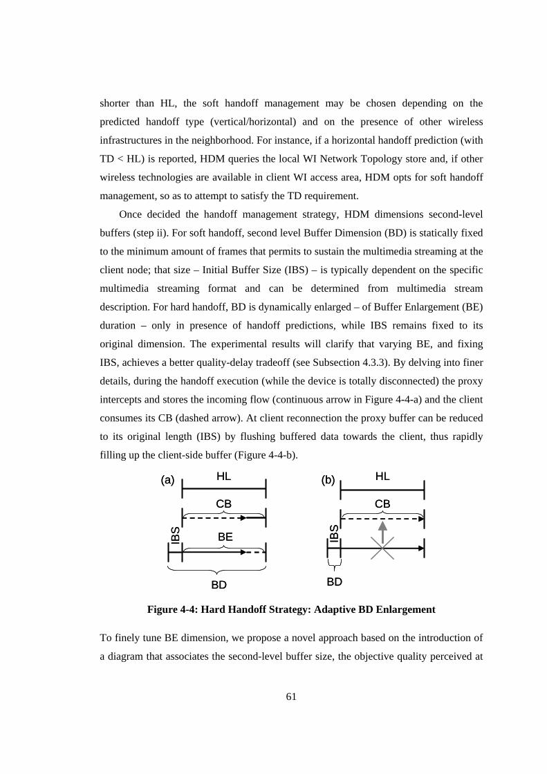
61
shorter than HL, the soft handoff management may be chosen depending on the
predicted handoff type (vertical/horizontal) and on the presence of other wireless
infrastructures in the neighborhood. For instance, if a horizontal handoff prediction (with
TD < HL) is reported, HDM queries the local WI Network Topology store and, if other
wireless technologies are available in client WI access area, HDM opts for soft handoff
management, so as to attempt to satisfy the TD requirement.
Once decided the handoff management strategy, HDM dimensions second-level
buffers (step ii). For soft handoff, second level Buffer Dimension (BD) is statically fixed
to the minimum amount of frames that permits to sustain the multimedia streaming at the
client node; that size – Initial Buffer Size (IBS) – is typically dependent on the specific
multimedia streaming format and can be determined from multimedia stream
description. For hard handoff, BD is dynamically enlarged – of Buffer Enlargement (BE)
duration – only in presence of handoff predictions, while IBS remains fixed to its
original dimension. The experimental results will clarify that varying BE, and fixing
IBS, achieves a better quality-delay tradeoff (see Subsection 4.3.3). By delving into finer
details, during the handoff execution (while the device is totally disconnected) the proxy
intercepts and stores the incoming flow (continuous arrow in Figure 4-4-a) and the client
consumes its CB (dashed arrow). At client reconnection the proxy buffer can be reduced
to its original length (IBS) by flushing buffered data towards the client, thus rapidly
filling up the client-side buffer (Figure 4-4-b).
HL
CB
IBS BE
(a) HL
CB
IBS
(b)
BD BD
HL
CB
IBS BE
(a) HL
CB
IBS
(b)
BD BD
Figure 4-4: Hard Handoff Strategy: Adaptive BD Enlargement
To finely tune BE dimension, we propose a novel approach based on the introduction of
a diagram that associates the second-level buffer size, the objective quality perceived at
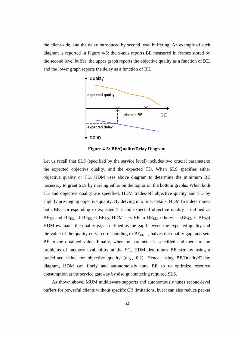
62
the client-side, and the delay introduced by second level buffering. An example of such
diagram is reported in Figure 4-5: the x-axis reports BE measured in frames stored by
the second level buffer; the upper graph reports the objective quality as a function of BE,
and the lower graph reports the delay as a function of BE.
Figure 4-5: BE/Quality/Delay Diagram
Let us recall that SLS (specified by the service level) includes two crucial parameters:
the expected objective quality, and the expected TD. When SLS specifies either
objective quality or TD, HDM uses above diagram to determine the minimum BE
necessary to grant SLS by moving either on the top or on the bottom graphs. When both
TD and objective quality are specified, HDM trades-off objective quality and TD by
slightly privileging objective quality. By delving into finer details, HDM first determines
both BEs corresponding to expected TD and expected objective quality – defined as
BEED and BEEQ; if BEEQ < BEED, HDM sets BE to BEED; otherwise (BEED < BEEQ)
HDM evaluates the quality gap – defined as the gap between the expected quality and
the value of the quality curve corresponding to BEED –, halves the quality gap, and sets
BE to the obtained value. Finally, when no parameter is specified and there are no
problems of memory availability at the SG, HDM determines BE size by using a
predefined value for objective quality (e.g., 0.2). Hence, using BE/Quality/Delay
diagram, HDM can finely and autonomously tune BE so to optimize resource
consumption at the service gateway by also guaranteeing required SLS.
As shown above, MUM middleware supports and autonomously tunes second-level
buffers for powerful clients without specific CB limitations, but it can also reduce packet
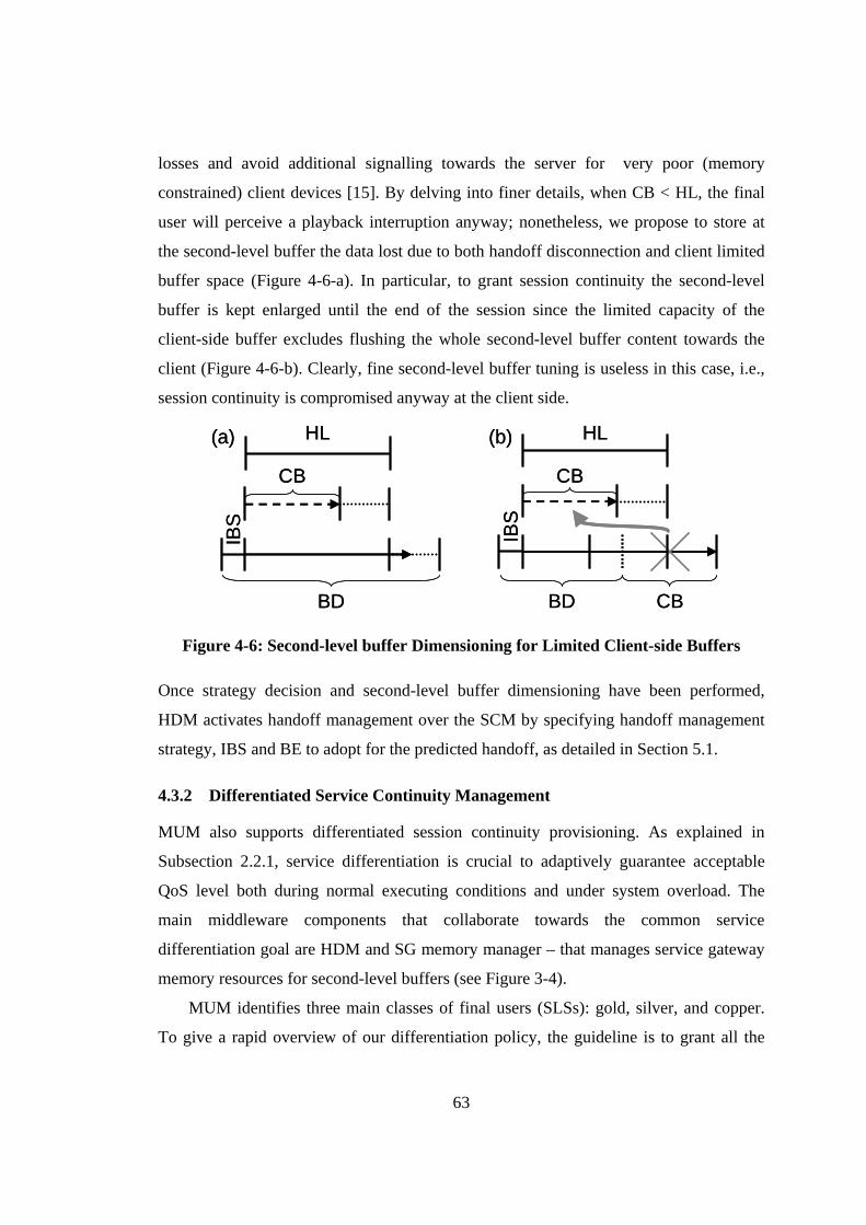
63
losses and avoid additional signalling towards the server for very poor (memory
constrained) client devices [15]. By delving into finer details, when CB < HL, the final
user will perceive a playback interruption anyway; nonetheless, we propose to store at
the second-level buffer the data lost due to both handoff disconnection and client limited
buffer space (Figure 4-6-a). In particular, to grant session continuity the second-level
buffer is kept enlarged until the end of the session since the limited capacity of the
client-side buffer excludes flushing the whole second-level buffer content towards the
client (Figure 4-6-b). Clearly, fine second-level buffer tuning is useless in this case, i.e.,
session continuity is compromised anyway at the client side.
HL
CB
BD
IBS
(a) HL
CB
BD
IBS
(a) (b) HL
CB
BD
IBS
CB
(b) HL
CB
BD
IBS
CB
Figure 4-6: Second-level buffer Dimensioning for Limited Client-side Buffers
Once strategy decision and second-level buffer dimensioning have been performed,
HDM activates handoff management over the SCM by specifying handoff management
strategy, IBS and BE to adopt for the predicted handoff, as detailed in Section 5.1.
4.3.2 Differentiated Service Continuity Management
MUM also supports differentiated session continuity provisioning. As explained in
Subsection 2.2.1, service differentiation is crucial to adaptively guarantee acceptable
QoS level both during normal executing conditions and under system overload. The
main middleware components that collaborate towards the common service
differentiation goal are HDM and SG memory manager – that manages service gateway
memory resources for second-level buffers (see Figure 3-4).
MUM identifies three main classes of final users (SLSs): gold, silver, and copper.
To give a rapid overview of our differentiation policy, the guideline is to grant all the
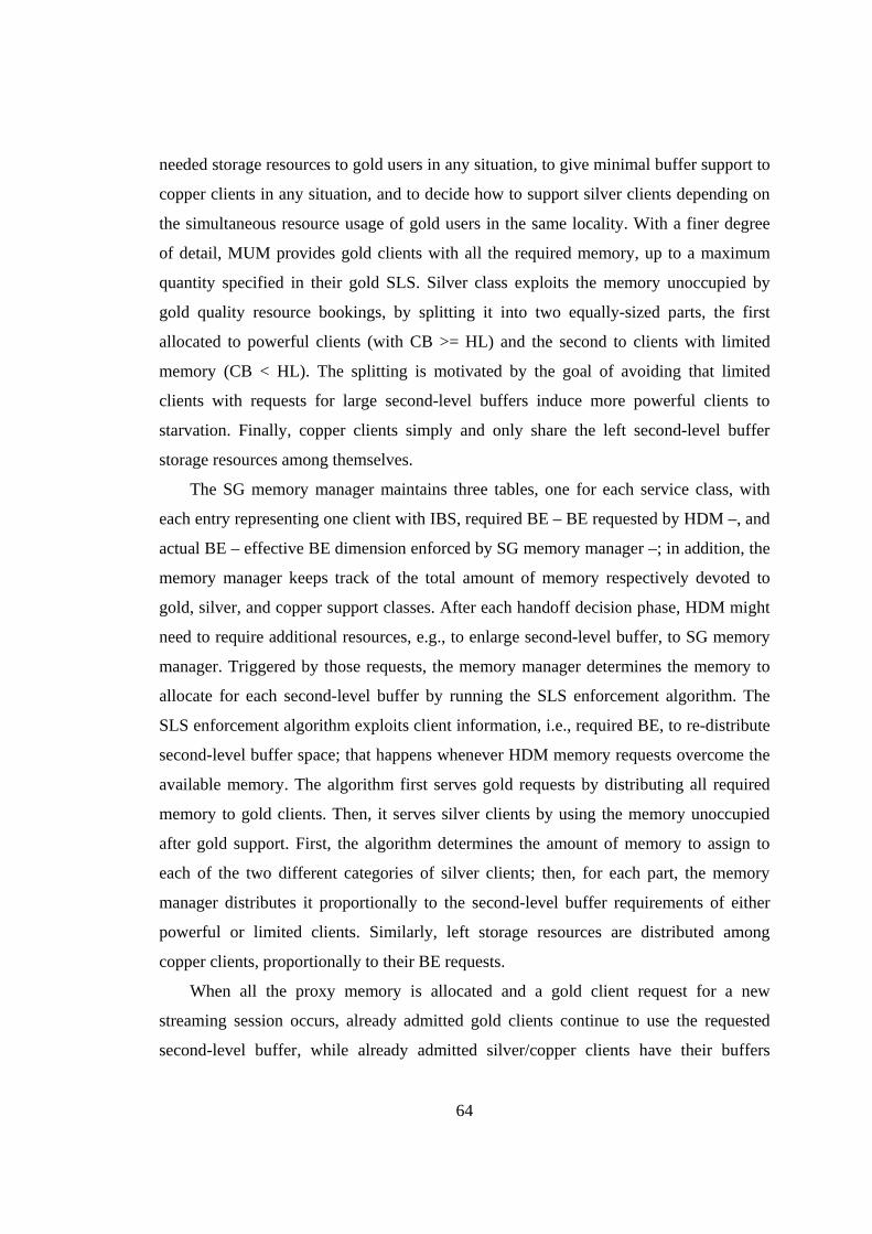
64
needed storage resources to gold users in any situation, to give minimal buffer support to
copper clients in any situation, and to decide how to support silver clients depending on
the simultaneous resource usage of gold users in the same locality. With a finer degree
of detail, MUM provides gold clients with all the required memory, up to a maximum
quantity specified in their gold SLS. Silver class exploits the memory unoccupied by
gold quality resource bookings, by splitting it into two equally-sized parts, the first
allocated to powerful clients (with CB >= HL) and the second to clients with limited
memory (CB < HL). The splitting is motivated by the goal of avoiding that limited
clients with requests for large second-level buffers induce more powerful clients to
starvation. Finally, copper clients simply and only share the left second-level buffer
storage resources among themselves.
The SG memory manager maintains three tables, one for each service class, with
each entry representing one client with IBS, required BE – BE requested by HDM –, and
actual BE – effective BE dimension enforced by SG memory manager –; in addition, the
memory manager keeps track of the total amount of memory respectively devoted to
gold, silver, and copper support classes. After each handoff decision phase, HDM might
need to require additional resources, e.g., to enlarge second-level buffer, to SG memory
manager. Triggered by those requests, the memory manager determines the memory to
allocate for each second-level buffer by running the SLS enforcement algorithm. The
SLS enforcement algorithm exploits client information, i.e., required BE, to re-distribute
second-level buffer space; that happens whenever HDM memory requests overcome the
available memory. The algorithm first serves gold requests by distributing all required
memory to gold clients. Then, it serves silver clients by using the memory unoccupied
after gold support. First, the algorithm determines the amount of memory to assign to
each of the two different categories of silver clients; then, for each part, the memory
manager distributes it proportionally to the second-level buffer requirements of either
powerful or limited clients. Similarly, left storage resources are distributed among
copper clients, proportionally to their BE requests.
When all the proxy memory is allocated and a gold client request for a new
streaming session occurs, already admitted gold clients continue to use the requested
second-level buffer, while already admitted silver/copper clients have their buffers
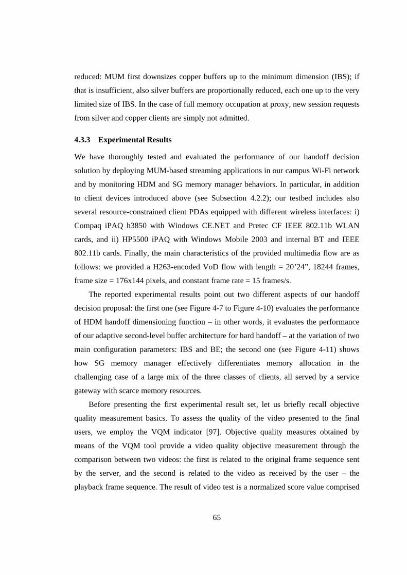
65
reduced: MUM first downsizes copper buffers up to the minimum dimension (IBS); if
that is insufficient, also silver buffers are proportionally reduced, each one up to the very
limited size of IBS. In the case of full memory occupation at proxy, new session requests
from silver and copper clients are simply not admitted.
4.3.3 Experimental Results
We have thoroughly tested and evaluated the performance of our handoff decision
solution by deploying MUM-based streaming applications in our campus Wi-Fi network
and by monitoring HDM and SG memory manager behaviors. In particular, in addition
to client devices introduced above (see Subsection 4.2.2); our testbed includes also
several resource-constrained client PDAs equipped with different wireless interfaces: i)
Compaq iPAQ h3850 with Windows CE.NET and Pretec CF IEEE 802.11b WLAN
cards, and ii) HP5500 iPAQ with Windows Mobile 2003 and internal BT and IEEE
802.11b cards. Finally, the main characteristics of the provided multimedia flow are as
follows: we provided a H263-encoded VoD flow with length = 20’24”, 18244 frames,
frame size = 176x144 pixels, and constant frame rate = 15 frames/s.
The reported experimental results point out two different aspects of our handoff
decision proposal: the first one (see Figure 4-7 to Figure 4-10) evaluates the performance
of HDM handoff dimensioning function – in other words, it evaluates the performance
of our adaptive second-level buffer architecture for hard handoff – at the variation of two
main configuration parameters: IBS and BE; the second one (see Figure 4-11) shows
how SG memory manager effectively differentiates memory allocation in the
challenging case of a large mix of the three classes of clients, all served by a service
gateway with scarce memory resources.
Before presenting the first experimental result set, let us briefly recall objective
quality measurement basics. To assess the quality of the video presented to the final
users, we employ the VQM indicator [97]. Objective quality measures obtained by
means of the VQM tool provide a video quality objective measurement through the
comparison between two videos: the first is related to the original frame sequence sent
by the server, and the second is related to the video as received by the user – the
playback frame sequence. The result of video test is a normalized score value comprised
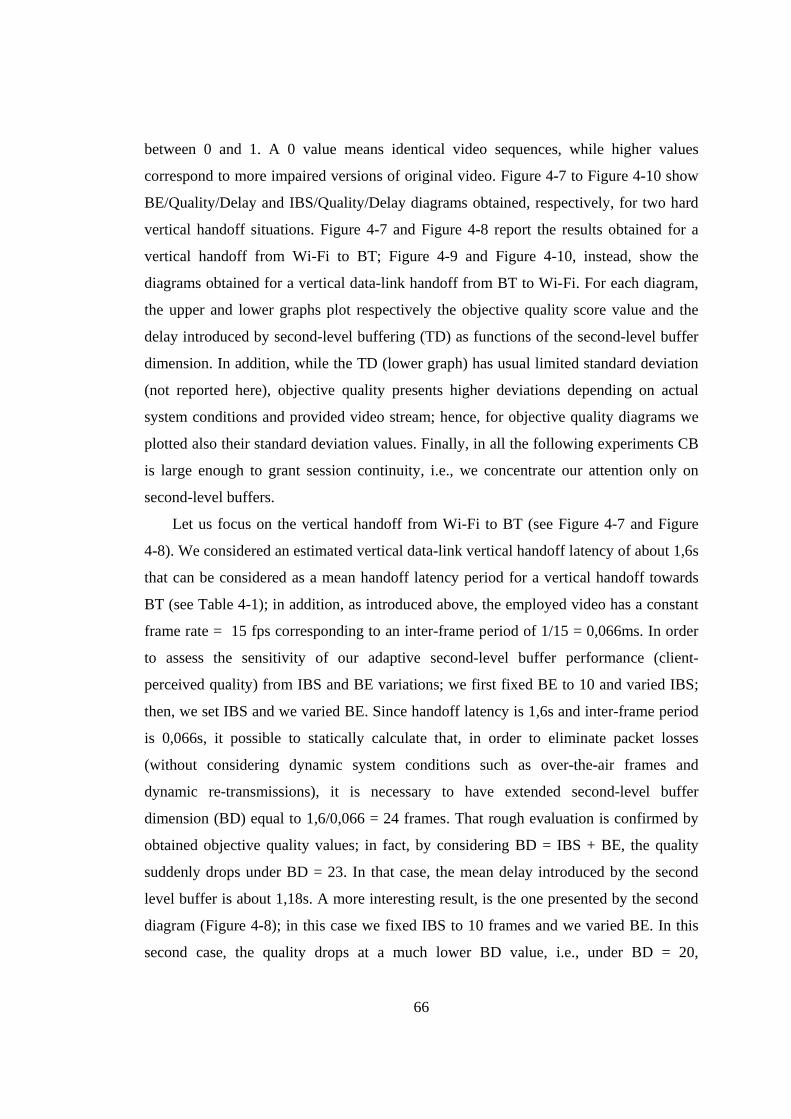
66
between 0 and 1. A 0 value means identical video sequences, while higher values
correspond to more impaired versions of original video. Figure 4-7 to Figure 4-10 show
BE/Quality/Delay and IBS/Quality/Delay diagrams obtained, respectively, for two hard
vertical handoff situations. Figure 4-7 and Figure 4-8 report the results obtained for a
vertical handoff from Wi-Fi to BT; Figure 4-9 and Figure 4-10, instead, show the
diagrams obtained for a vertical data-link handoff from BT to Wi-Fi. For each diagram,
the upper and lower graphs plot respectively the objective quality score value and the
delay introduced by second-level buffering (TD) as functions of the second-level buffer
dimension. In addition, while the TD (lower graph) has usual limited standard deviation
(not reported here), objective quality presents higher deviations depending on actual
system conditions and provided video stream; hence, for objective quality diagrams we
plotted also their standard deviation values. Finally, in all the following experiments CB
is large enough to grant session continuity, i.e., we concentrate our attention only on
second-level buffers.
Let us focus on the vertical handoff from Wi-Fi to BT (see Figure 4-7 and Figure
4-8). We considered an estimated vertical data-link vertical handoff latency of about 1,6s
that can be considered as a mean handoff latency period for a vertical handoff towards
BT (see Table 4-1); in addition, as introduced above, the employed video has a constant
frame rate = 15 fps corresponding to an inter-frame period of 1/15 = 0,066ms. In order
to assess the sensitivity of our adaptive second-level buffer performance (client-
perceived quality) from IBS and BE variations; we first fixed BE to 10 and varied IBS;
then, we set IBS and we varied BE. Since handoff latency is 1,6s and inter-frame period
is 0,066s, it possible to statically calculate that, in order to eliminate packet losses
(without considering dynamic system conditions such as over-the-air frames and
dynamic re-transmissions), it is necessary to have extended second-level buffer
dimension (BD) equal to 1,6/0,066 = 24 frames. That rough evaluation is confirmed by
obtained objective quality values; in fact, by considering BD = IBS + BE, the quality
suddenly drops under BD = 23. In that case, the mean delay introduced by the second
level buffer is about 1,18s. A more interesting result, is the one presented by the second
diagram (Figure 4-8); in this case we fixed IBS to 10 frames and we varied BE. In this
second case, the quality drops at a much lower BD value, i.e., under BD = 20,
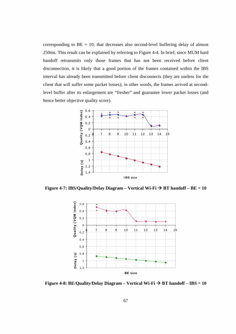
67
corresponding to BE = 10; that decreases also second-level buffering delay of almost
250ms. This result can be explained by referring to Figure 4-4. In brief, since MUM hard
handoff retransmits only those frames that has not been received before client
disconnection, it is likely that a good portion of the frames contained within the IBS
interval has already been transmitted before client disconnects (they are useless for the
client that will suffer some packet losses); in other words, the frames arrived at second-
level buffer after its enlargement are “fresher” and guarantee lower packet losses (and
hence better objective quality score).
-1,4
-1,2
-1
-0,8
-0,6
-0,4
-0,2
0
0,2
0,4
0,6
6 7 8 9 10 11 12 13 14 15
IBS size
Dela
y (
s) q
uality
(V
QM
in
dex)
Dela
y (
s)Q
uali
ty (
VQ
M i
nd
ex)
-1,4
-1,2
-1
-0,8
-0,6
-0,4
-0,2
0
0,2
0,4
0,6
6 7 8 9 10 11 12 13 14 15
IBS size
Dela
y (
s) q
uality
(V
QM
in
dex)
-1,4
-1,2
-1
-0,8
-0,6
-0,4
-0,2
0
0,2
0,4
0,6
6 7 8 9 10 11 12 13 14 15
IBS size
Dela
y (
s) q
uality
(V
QM
in
dex)
Dela
y (
s)Q
uali
ty (
VQ
M i
nd
ex)
Figure 4-7: IBS/Quality/Delay Diagram – Vertical Wi-Fi BT handoff – BE = 10
-1,2
-1
-0,8
-0,6
-0,4
-0,2
0
0,2
0,4
0,6
6 7 8 9 10 11 12 13 14 15
BE size
Dela
y (
s)Q
uali
ty (
VQ
M i
nd
ex)
-1,2
-1
-0,8
-0,6
-0,4
-0,2
0
0,2
0,4
0,6
6 7 8 9 10 11 12 13 14 15
BE size
Dela
y (
s)Q
uali
ty (
VQ
M i
nd
ex)
Figure 4-8: BE/Quality/Delay Diagram – Vertical Wi-Fi BT handoff – IBS = 10
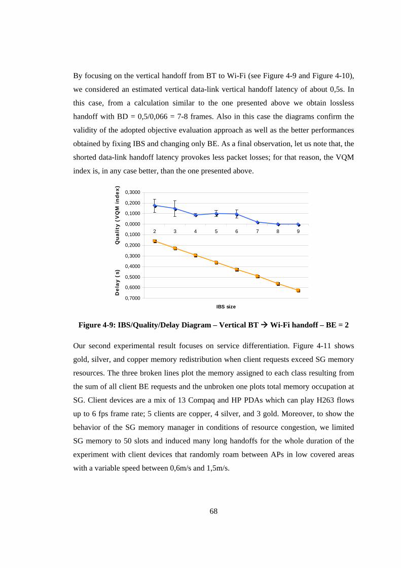
68
By focusing on the vertical handoff from BT to Wi-Fi (see Figure 4-9 and Figure 4-10),
we considered an estimated vertical data-link vertical handoff latency of about 0,5s. In
this case, from a calculation similar to the one presented above we obtain lossless
handoff with BD = 0,5/0,066 = 7-8 frames. Also in this case the diagrams confirm the
validity of the adopted objective evaluation approach as well as the better performances
obtained by fixing IBS and changing only BE. As a final observation, let us note that, the
shorted data-link handoff latency provokes less packet losses; for that reason, the VQM
index is, in any case better, than the one presented above.
-0,7000
-0,6000
-0,5000
-0,4000
-0,3000
-0,2000
-0,1000
0,0000
0,1000
0,2000
0,3000
2 3 4 5 6 7 8 9
IBS size
Dela
y (
s)Q
uali
ty (
VQ
M i
nd
ex)
-0,7000
-0,6000
-0,5000
-0,4000
-0,3000
-0,2000
-0,1000
0,0000
0,1000
0,2000
0,3000
2 3 4 5 6 7 8 9
IBS size-0,7000
-0,6000
-0,5000
-0,4000
-0,3000
-0,2000
-0,1000
0,0000
0,1000
0,2000
0,3000
2 3 4 5 6 7 8 9
IBS size
Dela
y (
s)Q
uali
ty (
VQ
M i
nd
ex)
Figure 4-9: IBS/Quality/Delay Diagram – Vertical BT Wi-Fi handoff – BE = 2
Our second experimental result focuses on service differentiation. Figure 4-11 shows
gold, silver, and copper memory redistribution when client requests exceed SG memory
resources. The three broken lines plot the memory assigned to each class resulting from
the sum of all client BE requests and the unbroken one plots total memory occupation at
SG. Client devices are a mix of 13 Compaq and HP PDAs which can play H263 flows
up to 6 fps frame rate; 5 clients are copper, 4 silver, and 3 gold. Moreover, to show the
behavior of the SG memory manager in conditions of resource congestion, we limited
SG memory to 50 slots and induced many long handoffs for the whole duration of the
experiment with client devices that randomly roam between APs in low covered areas
with a variable speed between 0,6m/s and 1,5m/s.
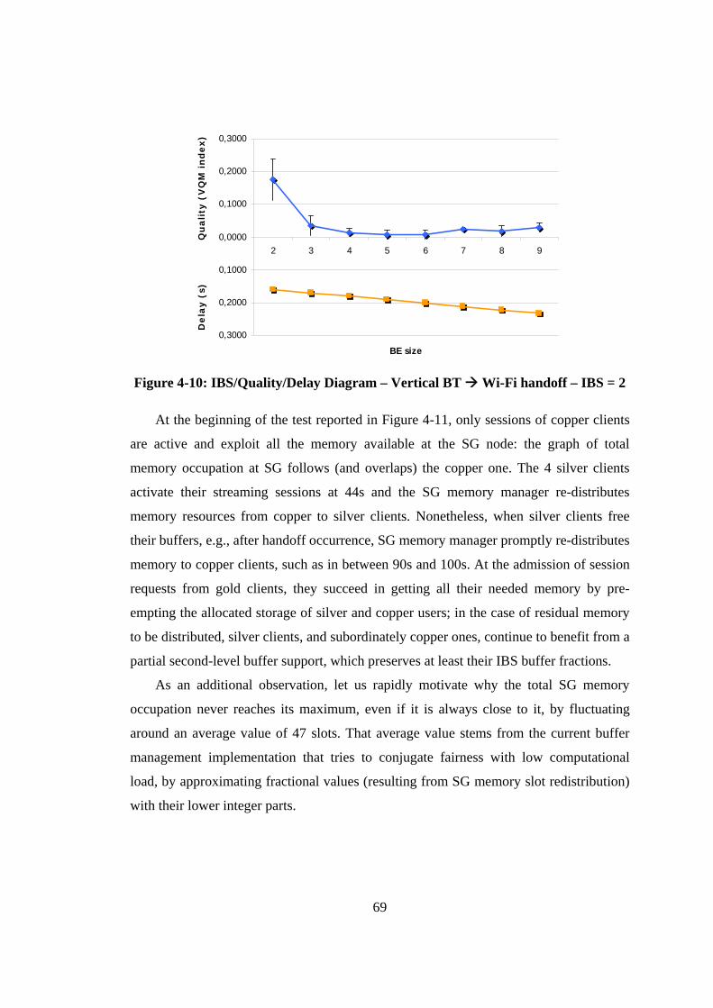
69
-0,3000
-0,2000
-0,1000
0,0000
0,1000
0,2000
0,3000
2 3 4 5 6 7 8 9
BE size
Dela
y (
s)Q
uali
ty (
VQ
M i
nd
ex)
-0,3000
-0,2000
-0,1000
0,0000
0,1000
0,2000
0,3000
2 3 4 5 6 7 8 9
BE size
Dela
y (
s)Q
uali
ty (
VQ
M i
nd
ex)
Figure 4-10: IBS/Quality/Delay Diagram – Vertical BT Wi-Fi handoff – IBS = 2
At the beginning of the test reported in Figure 4-11, only sessions of copper clients
are active and exploit all the memory available at the SG node: the graph of total
memory occupation at SG follows (and overlaps) the copper one. The 4 silver clients
activate their streaming sessions at 44s and the SG memory manager re-distributes
memory resources from copper to silver clients. Nonetheless, when silver clients free
their buffers, e.g., after handoff occurrence, SG memory manager promptly re-distributes
memory to copper clients, such as in between 90s and 100s. At the admission of session
requests from gold clients, they succeed in getting all their needed memory by pre-
empting the allocated storage of silver and copper users; in the case of residual memory
to be distributed, silver clients, and subordinately copper ones, continue to benefit from a
partial second-level buffer support, which preserves at least their IBS buffer fractions.
As an additional observation, let us rapidly motivate why the total SG memory
occupation never reaches its maximum, even if it is always close to it, by fluctuating
around an average value of 47 slots. That average value stems from the current buffer
management implementation that tries to conjugate fairness with low computational
load, by approximating fractional values (resulting from SG memory slot redistribution)
with their lower integer parts.
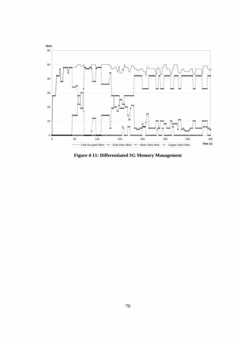
70
0
10
20
30
40
50
60
0 50 100 150 200 250 300 350
Time (s)
Slots
Total Occupied Slots Gold Class Slots Silver Class Slots Copper Class Slots
Figure 4-11: Differentiated SG Memory Management
71
5. Handoff Execution with Guaranteed QoS
This chapter presents the MUM support for handoff execution and session continuity;
especially, this chapter will focus on multimedia data management and delivery issues.
The three main goals of this part of the middleware – all related to the continuous
provisioning of multimedia flows – are: the execution of soft and hard handoff
management strategies, the management of other wireless QoS impairments (not strictly
related to handoff) that could undermine session continuity, and the adapted
provisioning of delivered multimedia contents.
Multimedia data session continuity management eliminates handoff impairments
effects – handoff latency and packet losses – and is obtained through strict coordination
between session proxy and client stub. Handoff execution is based on our adaptive two-
level buffering solution (see Subsection 3.3.1) and triggered by handoff decision: it takes
as input handoff strategy type (hard/soft) and second-level buffer dimensioning
parameterizations decided by HDM, dynamically modifies second-level buffer
dimension (if needed), and controls data re/transmissions between session proxy and
client stub so to eliminate packet losses [15], [13].
Wireless QoS management is crucial to smooth specific technology-related
impairments that could undermine session continuity. The adopted approach is to
provide QoS-awareness (see Section 3.1) of wireless impairments at the middleware
mechanism layer so to mask specific technology-related QoS issues to the upper facility
layer. In particular, we will present our original application-level solution for the IEEE
802.11 anomaly introduced in Subsection 2.1.3.
Finally, multimedia flow adaptation is necessary to tailor full-quality multimedia
contents, e.g., obtained by traditional Internet multimedia servers, so to fit service
provisioning constraints imposed by the actual WI provisioning environment. In
particular, MUM has been adopted to realize a distributed and open architecture – called
MUM Open Caching (MUMOC) – for Video on Demand (VoD) content provisioning
towards mobile and resource constrained client devices (with limited memory, CPU
power, frame sizes, …). MUMOC supports personalized VoD access via dynamic
downscale of the provided multimedia contents at service gateways and obtains
openness and easy interoperability with legacy VoD services by adopting standard
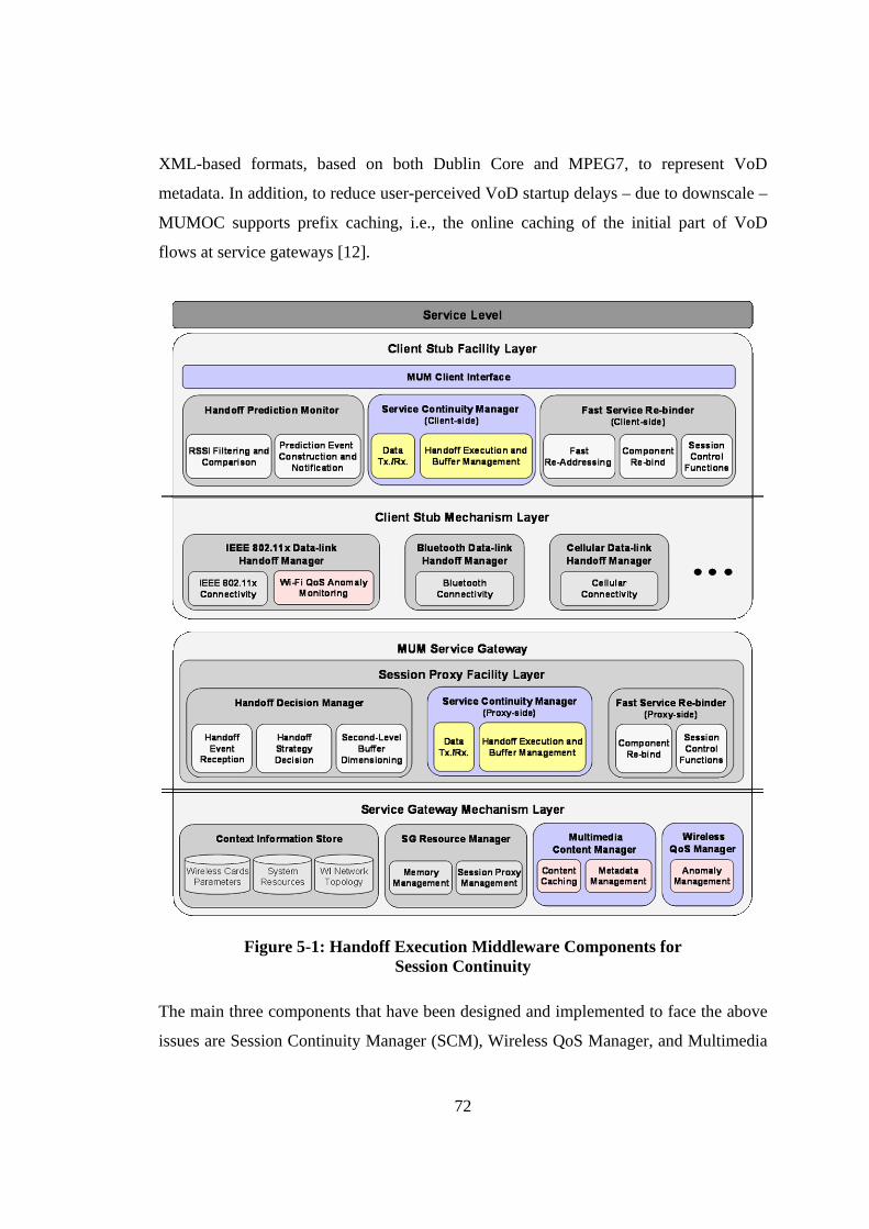
72
XML-based formats, based on both Dublin Core and MPEG7, to represent VoD
metadata. In addition, to reduce user-perceived VoD startup delays – due to downscale –
MUMOC supports prefix caching, i.e., the online caching of the initial part of VoD
flows at service gateways [12].
Figure 5-1: Handoff Execution Middleware Components for Session Continuity
The main three components that have been designed and implemented to face the above
issues are Session Continuity Manager (SCM), Wireless QoS Manager, and Multimedia
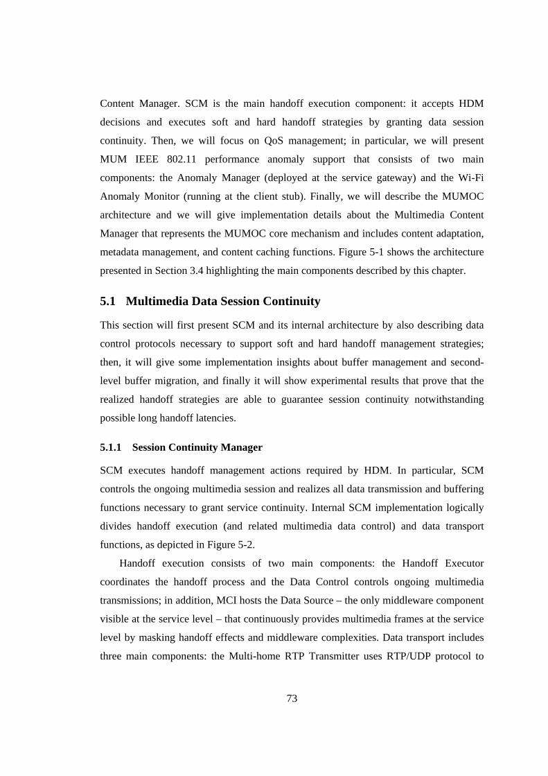
73
Content Manager. SCM is the main handoff execution component: it accepts HDM
decisions and executes soft and hard handoff strategies by granting data session
continuity. Then, we will focus on QoS management; in particular, we will present
MUM IEEE 802.11 performance anomaly support that consists of two main
components: the Anomaly Manager (deployed at the service gateway) and the Wi-Fi
Anomaly Monitor (running at the client stub). Finally, we will describe the MUMOC
architecture and we will give implementation details about the Multimedia Content
Manager that represents the MUMOC core mechanism and includes content adaptation,
metadata management, and content caching functions. Figure 5-1 shows the architecture
presented in Section 3.4 highlighting the main components described by this chapter.
5.1 Multimedia Data Session Continuity
This section will first present SCM and its internal architecture by also describing data
control protocols necessary to support soft and hard handoff management strategies;
then, it will give some implementation insights about buffer management and second-
level buffer migration, and finally it will show experimental results that prove that the
realized handoff strategies are able to guarantee session continuity notwithstanding
possible long handoff latencies.
5.1.1 Session Continuity Manager
SCM executes handoff management actions required by HDM. In particular, SCM
controls the ongoing multimedia session and realizes all data transmission and buffering
functions necessary to grant service continuity. Internal SCM implementation logically
divides handoff execution (and related multimedia data control) and data transport
functions, as depicted in Figure 5-2.
Handoff execution consists of two main components: the Handoff Executor
coordinates the handoff process and the Data Control controls ongoing multimedia
transmissions; in addition, MCI hosts the Data Source – the only middleware component
visible at the service level – that continuously provides multimedia frames at the service
level by masking handoff effects and middleware complexities. Data transport includes
three main components: the Multi-home RTP Transmitter uses RTP/UDP protocol to
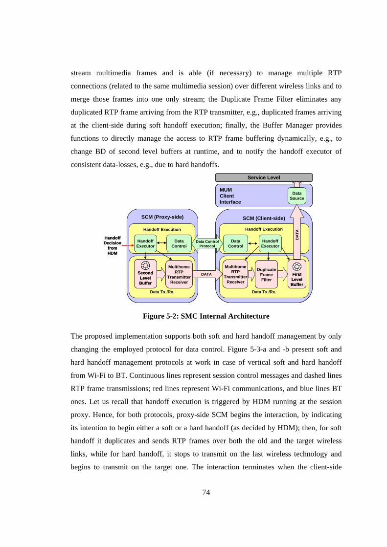
74
stream multimedia frames and is able (if necessary) to manage multiple RTP
connections (related to the same multimedia session) over different wireless links and to
merge those frames into one only stream; the Duplicate Frame Filter eliminates any
duplicated RTP frame arriving from the RTP transmitter, e.g., duplicated frames arriving
at the client-side during soft handoff execution; finally, the Buffer Manager provides
functions to directly manage the access to RTP frame buffering dynamically, e.g., to
change BD of second level buffers at runtime, and to notify the handoff executor of
consistent data-losses, e.g., due to hard handoffs.
MUMClientInterface
SCM (Proxy-side) SCM (Client-side)
Data Tx./Rx.Data Tx./Rx.
Handoff Execution
SecondLevelBuffer
MultihomeRTP
TransmitterReceiver
Handoff Execution
MultihomeRTP
TransmitterReceiver
FirstLevelBuffer
DataControl
DataControl
DataSource
HandoffDecision
from HDM
DATA
Data ControlProtocol
HandoffExecutor
HandoffExecutor
DA
TA
DuplicateFrameFilter
Service Level
MUMClientInterface
SCM (Proxy-side) SCM (Client-side)
Data Tx./Rx.Data Tx./Rx.
Handoff Execution
SecondLevelBuffer
SecondLevelBuffer
SecondLevelBuffer
MultihomeRTP
TransmitterReceiver
MultihomeRTP
TransmitterReceiver
Handoff Execution
MultihomeRTP
TransmitterReceiver
MultihomeRTP
TransmitterReceiver
FirstLevelBuffer
FirstLevelBuffer
FirstLevelBuffer
DataControl
DataControl
DataSource
HandoffDecision
from HDM
DATA
Data ControlProtocol
HandoffExecutor
HandoffExecutor
DA
TA
DuplicateFrameFilter
DuplicateFrameFilter
Service Level
Figure 5-2: SMC Internal Architecture
The proposed implementation supports both soft and hard handoff management by only
changing the employed protocol for data control. Figure 5-3-a and -b present soft and
hard handoff management protocols at work in case of vertical soft and hard handoff
from Wi-Fi to BT. Continuous lines represent session control messages and dashed lines
RTP frame transmissions; red lines represent Wi-Fi communications, and blue lines BT
ones. Let us recall that handoff execution is triggered by HDM running at the session
proxy. Hence, for both protocols, proxy-side SCM begins the interaction, by indicating
its intention to begin either a soft or a hard handoff (as decided by HDM); then, for soft
handoff it duplicates and sends RTP frames over both the old and the target wireless
links, while for hard handoff, it stops to transmit on the last wireless technology and
begins to transmit on the target one. The interaction terminates when the client-side
75
SCM, once the client has connected to the target AP, either signals the reception of RTP
frames over the target wireless link (for soft handoff management) or requires the re-
transmission of all lost frames (for hard handoff, see also Figure 4-4 and Figure 4-6
presented in the previous chapter).
Client-side SCM
Stream overWi-Fi only
Stop streamover Wi-Fi
Stream overBT only
Stream overWi-Fi and BT
Prepare soft to BT
Lost RTP frames
frame 14frame 15
frame 21frame 22frame 16frame 17frame 18
Prepare hard to BT
Received Retransmission Req. from frame 16
(a) (b)
OK
Received OK
Proxy-side SCM Client-side SCM Proxy-side SCMClient-side SCMClient-side SCM
Stream overWi-Fi only
Stop streamover Wi-Fi
Stream overBT only
Stream overWi-Fi and BT
Prepare soft to BT
Lost RTP frames
frame 14frame 15
frame 21frame 22frame 16frame 17frame 18
Prepare hard to BT
Received Retransmission Req. from frame 16
(a) (b)
OK
Received OK
Proxy-side SCMProxy-side SCM Client-side SCMClient-side SCM Proxy-side SCMProxy-side SCM
Figure 5-3: Soft and Hard Handoff Management Protocols
The above protocols assume static knowledge of client stub/session proxy endpoints.
Nonetheless, during macro and global handoffs, client nodes change their IP network
addresses: that requires to re-address clients and to re-bind client stubs to their session
proxies – including RTP and data control endopoints renewal. Those two tasks, along
with all other session control issues will be tackled by Chapter 6.
To conclude this subsection, we want to sum up the whole MUM handoff
management process by presenting two complete use cases of soft and hard handoff
management from the notification of handoff predictions (HPM) to handoff decision
(HDM), and to execution (SCM). The first one is a soft handoff management of a video
flow generated by a video surveillance application with very strict jitter (and delay)
requirements (see Subsection 2.2.3); in particular, this first handoff case occurs in a
mixed WI infrastructure and takes advantage of a BT and Wi-Fi overlapping area to
seamlessly change wireless access technology (vertical macro handoff from BT to Wi-
Fi). The second one is a hard handoff of a live streaming video flow with looser delay
and jitter requirements, but low packet loss tolerance and involves two Wi-Fi cells that
belong to the same MUM domain and subnet (horizontal micro handoff) and shows
MUM differentiated service continuity management at works (see Subsection 4.3.1).
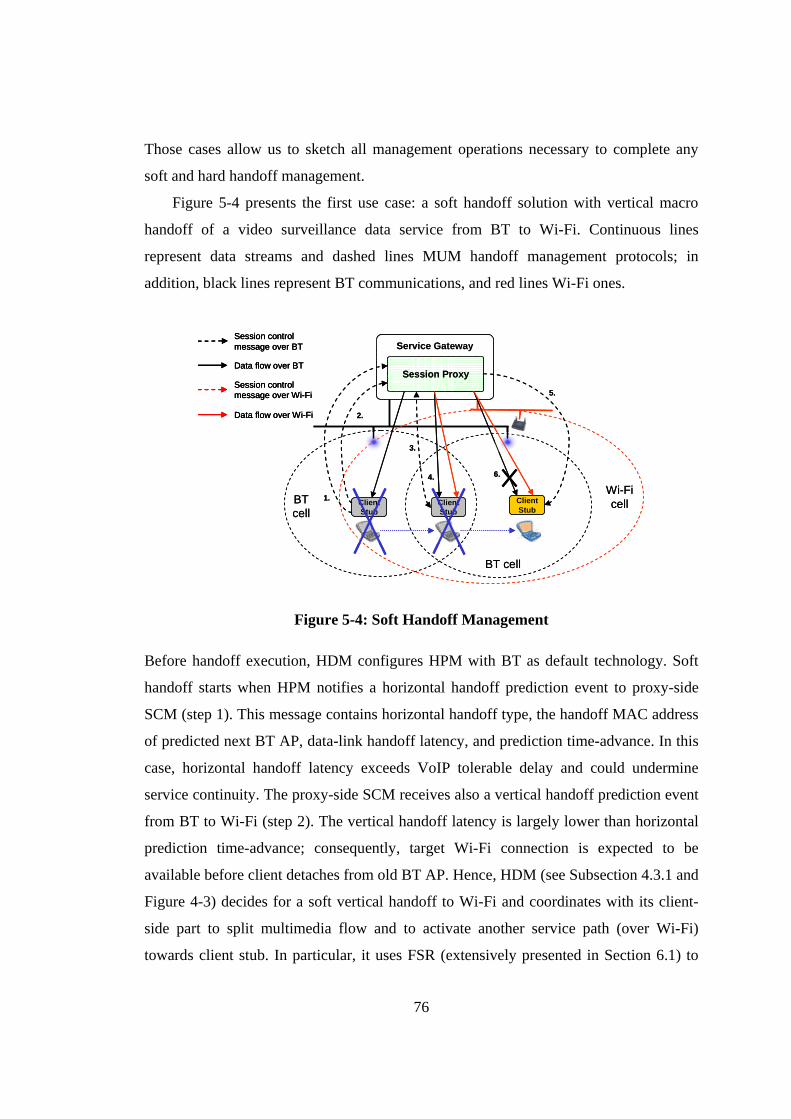
76
Those cases allow us to sketch all management operations necessary to complete any
soft and hard handoff management.
Figure 5-4 presents the first use case: a soft handoff solution with vertical macro
handoff of a video surveillance data service from BT to Wi-Fi. Continuous lines
represent data streams and dashed lines MUM handoff management protocols; in
addition, black lines represent BT communications, and red lines Wi-Fi ones.
Service Gateway
Session Proxy
ClientStub
BTcell
BT cell
ClientStub
1.
2.
3.
4.
ClientStub
6.
5.
Wi-Ficell
Session control message over BT
Data flow over BT
Session control message over Wi-Fi
Data flow over Wi-Fi
Service Gateway
Session Proxy
ClientStub
BTcell
BT cell
ClientStub
1.
2.
3.
4.
ClientStub
6.
5.
Wi-Ficell
Session control message over BT
Data flow over BT
Session control message over Wi-Fi
Data flow over Wi-Fi
Session control message over BT
Data flow over BT
Session control message over Wi-Fi
Data flow over Wi-Fi
Figure 5-4: Soft Handoff Management
Before handoff execution, HDM configures HPM with BT as default technology. Soft
handoff starts when HPM notifies a horizontal handoff prediction event to proxy-side
SCM (step 1). This message contains horizontal handoff type, the handoff MAC address
of predicted next BT AP, data-link handoff latency, and prediction time-advance. In this
case, horizontal handoff latency exceeds VoIP tolerable delay and could undermine
service continuity. The proxy-side SCM receives also a vertical handoff prediction event
from BT to Wi-Fi (step 2). The vertical handoff latency is largely lower than horizontal
prediction time-advance; consequently, target Wi-Fi connection is expected to be
available before client detaches from old BT AP. Hence, HDM (see Subsection 4.3.1 and
Figure 4-3) decides for a soft vertical handoff to Wi-Fi and coordinates with its client-
side part to split multimedia flow and to activate another service path (over Wi-Fi)
towards client stub. In particular, it uses FSR (extensively presented in Section 6.1) to
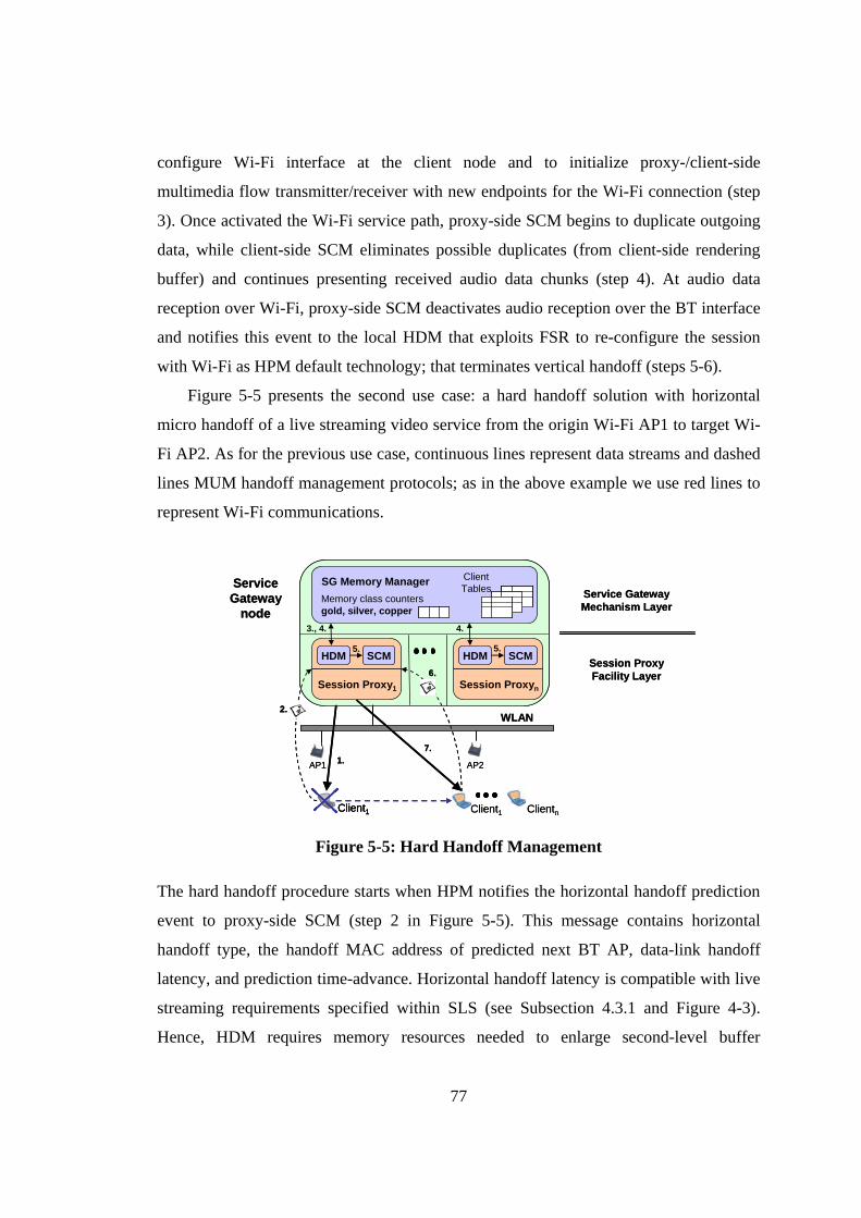
77
configure Wi-Fi interface at the client node and to initialize proxy-/client-side
multimedia flow transmitter/receiver with new endpoints for the Wi-Fi connection (step
3). Once activated the Wi-Fi service path, proxy-side SCM begins to duplicate outgoing
data, while client-side SCM eliminates possible duplicates (from client-side rendering
buffer) and continues presenting received audio data chunks (step 4). At audio data
reception over Wi-Fi, proxy-side SCM deactivates audio reception over the BT interface
and notifies this event to the local HDM that exploits FSR to re-configure the session
with Wi-Fi as HPM default technology; that terminates vertical handoff (steps 5-6).
Figure 5-5 presents the second use case: a hard handoff solution with horizontal
micro handoff of a live streaming video service from the origin Wi-Fi AP1 to target Wi-
Fi AP2. As for the previous use case, continuous lines represent data streams and dashed
lines MUM handoff management protocols; as in the above example we use red lines to
represent Wi-Fi communications.
Session Proxy1
7.
Session Proxyn
AP1
Client1
WLAN
AP2
Client1
Service Gateway
node
1.
6.
2.
SG Memory Manager Client Tables
Memory class countersgold, silver, copper
Clientn
Service Gateway Mechanism Layer
Session ProxyFacility Layer
HDM SCM HDM SCM
3., 4.
5.
4.
5.
Session Proxy1
7.
Session Proxyn
AP1
Client1Client1
WLAN
AP2
Client1
Service Gateway
node
1.
6.6.
2.2.
SG Memory Manager Client Tables
Memory class countersgold, silver, copper
Clientn
Service Gateway Mechanism Layer
Session ProxyFacility Layer
HDM SCM HDM SCM
3., 4.
5.
4.
5.
Figure 5-5: Hard Handoff Management
The hard handoff procedure starts when HPM notifies the horizontal handoff prediction
event to proxy-side SCM (step 2 in Figure 5-5). This message contains horizontal
handoff type, the handoff MAC address of predicted next BT AP, data-link handoff
latency, and prediction time-advance. Horizontal handoff latency is compatible with live
streaming requirements specified within SLS (see Subsection 4.3.1 and Figure 4-3).
Hence, HDM requires memory resources needed to enlarge second-level buffer
78
dimension (BD) to SG memory manager (step 3), and SG memory manager re-
distributes available resource – according and to client SLSs and coordinating with
HDMs that manage and command necessary BD variations over their SCMs (step 4-5).
During handoff, when a client is disconnected from its origin AP and not yet re-
connected at the destination one, the proxy continues to buffer incoming multimedia
streams as in normal conditions by using the storage resources assigned by the memory
manager, while the player uses client-side buffered frames to sustain flow rendering.
When the client re-establishes Wi-Fi connectivity in the destination cell, our middleware
starts resuming operations for its streaming session by communicating to the proxy the
timestamp of the last RTP packet received (step 6); that message forces the
retransmission of all those RTP packets following the last one received by the client
(step 7). After the handoff, BD is reduced and the freed resources are re-distributed by
SG memory manager – as specified in Subsection 4.3.2 – among all other second-level
buffers (not shown in figure). Let us finally note that when the system is heavy loaded
and SG memory manager (through HDM) enforces second-level buffer downsize, i.e.,
enforces a BD reduction, MUM works not to waste the already pre-fetched flow: MUM
first accelerates the proxy-to-client transmission of buffered data and, if the client does
not sustain this accelerated flow, it selectively discards some buffered frames, by
favoring streaming continuity with regards to visualization quality.
5.1.2 Two-Level Buffering Implementation Insights
This subsection presents the primary core mechanism of the MUM handoff facility, i.e.,
the second-level buffering mechanism. MUM employs standard application-level
protocols whenever possible, to ease MUM integration with more traditional continuous
service provisioning infrastructures. Our middleware employs the RealTime Protocol
(RTP) and the RealTime Control Protocol (RTCP) to transmit, monitor, and control
multimedia data streaming [81]: RTP is already a de-facto standard for multimedia
streaming and many enhancements have been proposed to improve protocol usability.
For instance, two RTCP extensions have been recently standardized to enable RTP
retransmissions; Data Control components employed those extensions to realize MUM
data control protocols (see Figure 5-2) [71], [74].
79
To facilitate portability MUM is implemented in Java and exploits pure-Java
technologies, in particular, we exploit the SUN Java Media Framework (JMF) for RTP-
based video streaming [103]. We developed a proactive buffer prototype, implemented
in terms of a circular buffer, to verify the feasibility of the MUM approach from the
performance point of view, also when adopting the application-level Java-based JMF. In
the following, we first present some main elements of JMF, needed for the full
understanding of presented implementation details, and then we detail the design and
implementation of the MUM buffer solution.
JMF is the SUN Java-based framework proposed for multimedia object
management. JMF adopts the RealTime Protocol (RTP) for video streaming and the
RealTime Control Protocol (RTCP) to monitor the network status at provision time. JMF
processes the frames of a multimedia flow by passing them through a pipeline, called
plug-in chain, composed of various stages; each plug-in can perform a specific flow
transformation. JMF simplifies multimedia application development by hiding frame
transformations at the library level and by providing higher level APIs both to abstract
frame sources/sinks, e.g., Data-Source/DataSink, and to encapsulate the
construction and usage of plug-in chains, e.g., Player and Processor. JMF is also
in charge of buffering functions and exposes APIs for flow buffering control, e.g., the
BufferControl object that can be obtained from Player or Processor via
getControl().
Let us note that high-level JMF APIs simplify multimedia application development,
but do not always offer the fine control granularity required to realize advanced and
customized services. Therefore, we have decided to develop an original buffering
mechanism outside JMF both to control directly buffering functions and to operate with
finer granularity directly at the frame level. The realized solution is highly portable and
can be employed also as a stand-alone buffering component. In particular, our buffer
mechanism enables all functions needed to extract, set, and manage directly the circular
buffer; JMF does not support this kind of functions. In addition, from our experience,
JMF buffering sometimes exhibits quite unpredictable performance, while our buffer is
directly under middleware control, and hence its performance can be optimized for
specific service requirements and depending on underlying computing platform.
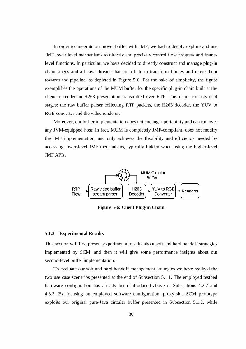
80
In order to integrate our novel buffer with JMF, we had to deeply explore and use
JMF lower level mechanisms to directly and precisely control flow progress and frame-
level functions. In particular, we have decided to directly construct and manage plug-in
chain stages and all Java threads that contribute to transform frames and move them
towards the pipeline, as depicted in Figure 5-6. For the sake of simplicity, the figure
exemplifies the operations of the MUM buffer for the specific plug-in chain built at the
client to render an H263 presentation transmitted over RTP. This chain consists of 4
stages: the raw buffer parser collecting RTP packets, the H263 decoder, the YUV to
RGB converter and the video renderer.
Moreover, our buffer implementation does not endanger portability and can run over
any JVM-equipped host: in fact, MUM is completely JMF-compliant, does not modify
the JMF implementation, and only achieves the flexibility and efficiency needed by
accessing lower-level JMF mechanisms, typically hidden when using the higher-level
JMF APIs.
Raw video bufferstream parser
RTP Flow
H263Decoder
YUV to RGBConverter
MUM CircularBuffer
RendererRaw video bufferstream parser
RTP Flow
H263Decoder
YUV to RGBConverter
MUM CircularBuffer
Renderer
Figure 5-6: Client Plug-in Chain
5.1.3 Experimental Results
This section will first present experimental results about soft and hard handoff strategies
implemented by SCM, and then it will give some performance insights about out
second-level buffer implementation.
To evaluate our soft and hard handoff management strategies we have realized the
two use case scenarios presented at the end of Subsection 5.1.1. The employed testbed
hardware configuration has already been introduced above in Subsections 4.2.2 and
4.3.3. By focusing on employed software configuration, proxy-side SCM prototype
exploits our original pure-Java circular buffer presented in Subsection 5.1.2, while
81
client-side SCM have been optimized to run on both full-fledged laptop devices, but also
on more limited PDA devices equipped with Personal Java, e.g., Geode or crème
distributions [106], [107]. The following experimental results have been obtained while
provisioning a H263-encoded VoD flow; in particular, the first use case has been
obtained while provisioning a video surveillance service consisting of a H263-encoded
VoD flow (frame size = 176x144 pixels, constant frame rate = 8 frames/s) with buffer
slots storing H263 RTP packets (667B per packet on the average), while the second use
case has been obtained by providing a live streaming video service flow with similar
characteristics, but lower frame rate, i.e., 6 frames/s, which is the maximum frame rate
sustainable by more limited PDA devices.
The reported experimental results point out three different aspects of SCM: the first
one refers to soft handoff management use case and (see Figure 5-7) demonstrates how
soft handoff strategy can grant service continuity and limited memory consumption at
service gateway, the second one refers to hard handoff and (see Figure 5-8) shows that
accurate proxy-side buffer management can grant session continuity even to limited
clients; the third one also refers to hard handoff (see Figure 5-9) and proves how
accurate handoff-awareness, i.e., accurate knowledge of Wi-Fi data-link handoff
latencies, permits to save non-negligible memory resources at proxy.
The first experimental result is about MUM soft handoff management applied to a
vertical handoff; in particular, we will focus on the downward direction, i.e., from Wi-Fi
to BT, because it is the most challenging one due to the long time needed to attach BT
client card to BT AP. To better show soft management operations, Figure 5-7 focuses on
a restricted time interval that excludes only the time intervals required to attach client to
the BT infrastructure and to disconnect from Wi-Fi. With a closer view to details, we
report the effective filling of MUM buffers, i.e., the slot distance between buffer read
and write pointers, for the client and the proxy. Client buffer usage is measured after
duplicate frame elimination and we use two different symbols to discriminate H263
frames delivered over Wi-Fi (old) and BT (target) service paths. Square lines point out
time intervals of all main handoff steps executed at client side (continuous line) and at
proxy side (dashed line).
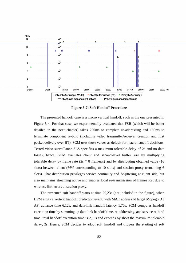
82
0
2
4
6
8
10
12
24250 24300 25450 25500 25550 25600 25650 25700 25750 25800 25850 25900
A B C
D
E
F
Client-side management actions Proxy-side management stepsClient buffer usage (Wi-Fi) Client buffer usage (BT) Proxy buffer usage
Slots
ms0
2
4
6
8
10
12
24250 24300 25450 25500 25550 25600 25650 25700 25750 25800 25850 25900
A B C
D
E
F
Client-side management actions Proxy-side management stepsClient-side management actionsClient-side management actions Proxy-side management stepsProxy-side management stepsClient buffer usage (Wi-Fi) Client buffer usage (BT) Proxy buffer usageClient buffer usage (Wi-Fi)Client buffer usage (Wi-Fi) Client buffer usage (BT)Client buffer usage (BT) Proxy buffer usageProxy buffer usage
Slots
ms
Figure 5-7: Soft Handoff Procedure
The presented handoff case is a macro vertical handoff, such as the one presented in
Figure 5-4. For that case, we experimentally evaluated that FSR (which will be better
detailed in the next chapter) takes 200ms to complete re-addressing and 150ms to
terminate component re-bind (including video transmitter/receiver creation and first
packet delivery over BT). SCM uses those values as default for macro handoff decisions.
Tested video surveillance SLS specifies a maximum tolerable delay of 2s and no data
losses; hence, SCM evaluates client and second-level buffer size by multiplying
tolerable delay by frame rate (2s * 8 frames/s) and by distributing obtained value (16
slots) between client (66% corresponding to 10 slots) and session proxy (remaining 6
slots). That distribution privileges service continuity and de-jittering at client side, but
also maintains streaming active and enables local re-transmission of frames lost due to
wireless link errors at session proxy.
The presented soft handoff starts at time 20,23s (not included in the figure), when
HPM emits a vertical handoff prediction event, with MAC address of target Mopogo BT
AP, advance time 6,12s, and data-link handoff latency 1,70s. SCM computes handoff
execution time by summing up data-link handoff time, re-addressing, and service re-bind
time: total handoff execution time is 2,05s and exceeds by short the maximum tolerable
delay, 2s. Hence, SCM decides to adopt soft handoff and triggers the starting of soft
83
handoff management operations at 24,30s. The reported client attach time to BT
infrastructure is faster than predicted one and terminates at 25,50s (step A, in Figure 5-7)
while client-side FSR completes re-addressing at 25,67s and promptly begins component
re-binding after a few milliseconds (steps B and C). Thereafter, we experimentally
verified that proxy-side SCM starts video duplication on BT at 25,69s (step D), while
component re-bind terminates at 25,78s when client-side definitely switches to BT after
receiving first H263 frames at 25,77s and eliminating last packets arriving on Wi-Fi
interface (step C). Soft handoff ends with Wi-Fi service path de-activation, which
requires only a dozen of milliseconds (steps E and F). To successfully execute soft
handoff, SCM must start BT service path before disconnecting from Wi-Fi AP. The
presented handoff case exhibits even better performances: the high prediction advance
time lets SCM terminate all soft management operations before the Wi-Fi disconnection
at 25,98s. In addition, soft handoff maintains inter-arrival data delay always below
160ms and does not require additional resources at either client or proxy.
The second experimental result shows how short client-side buffers influence BE
both during and after handoff; for further details about related handoff decision aspect as
well as for a better comprehension of all used acronyms, we refer the reader to
Subsection 4.3.1. In particular, we compared two gold clients executing over two
Compaq PDAs with identical settings except for their CB. The one with greater memory,
client1, can store up to 2,3s (14 slots at 6 fps frame rate), while the second, client2, can
store only 1,6s (10 slots). Those two clients move in a low covered area and incur in
long horizontal data-link handoff latency that, for the Pretec CF IEEE 802.11b WLAN
card last about 2,5s [15]. Figure 5-8 reports the proxy (at the top) and the client (at the
bottom) buffer usage/size during handoff. Proxy size is the total size of the second-level
buffer, i.e., IBS + BE, and IBS was fixed to about 2,5s (15 slots); proxy usage, instead,
represents the effective usage of the second-level buffer, i.e., the distance between buffer
read and write pointers.
Figure 5-8 reports the collected results starting from time 100s to let the middleware
complete startup operations, e.g., server start, session start, buffers filling up, ..., and to
let some handoffs occur to show how MUM buffer management behaves in normal
executing conditions. Proxy and client fluctuations are mainly due to network jitter
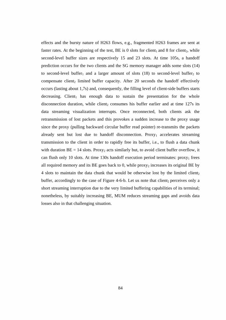
84
effects and the bursty nature of H263 flows, e.g., fragmented H263 frames are sent at
faster rates. At the beginning of the test, BE is 0 slots for client1 and 8 for client2, while
second-level buffer sizes are respectively 15 and 23 slots. At time 105s, a handoff
prediction occurs for the two clients and the SG memory manager adds some slots (14)
to second-level buffer1 and a larger amount of slots (18) to second-level buffer2 to
compensate client2 limited buffer capacity. After 20 seconds the handoff effectively
occurs (lasting about 1,7s) and, consequently, the filling level of client-side buffers starts
decreasing. Client1 has enough data to sustain the presentation for the whole
disconnection duration, while client2 consumes his buffer earlier and at time 127s its
data streaming visualization interrupts. Once reconnected, both clients ask the
retransmission of lost packets and this provokes a sudden increase to the proxy usage
since the proxy (pulling backward circular buffer read pointer) re-transmits the packets
already sent but lost due to handoff disconnection. Proxy1 accelerates streaming
transmission to the client in order to rapidly free its buffer, i.e., to flush a data chunk
with duration BE = 14 slots. Proxy2 acts similarly but, to avoid client buffer overflow, it
can flush only 10 slots. At time 130s handoff execution period terminates: proxy1 frees
all required memory and its BE goes back to 0, while proxy2 increases its original BE by
4 slots to maintain the data chunk that would be otherwise lost by the limited client2
buffer, accordingly to the case of Figure 4-6-b. Let us note that client2 perceives only a
short streaming interruption due to the very limited buffering capabilities of its terminal;
nonetheless, by suitably increasing BE, MUM reduces streaming gaps and avoids data
losses also in that challenging situation.
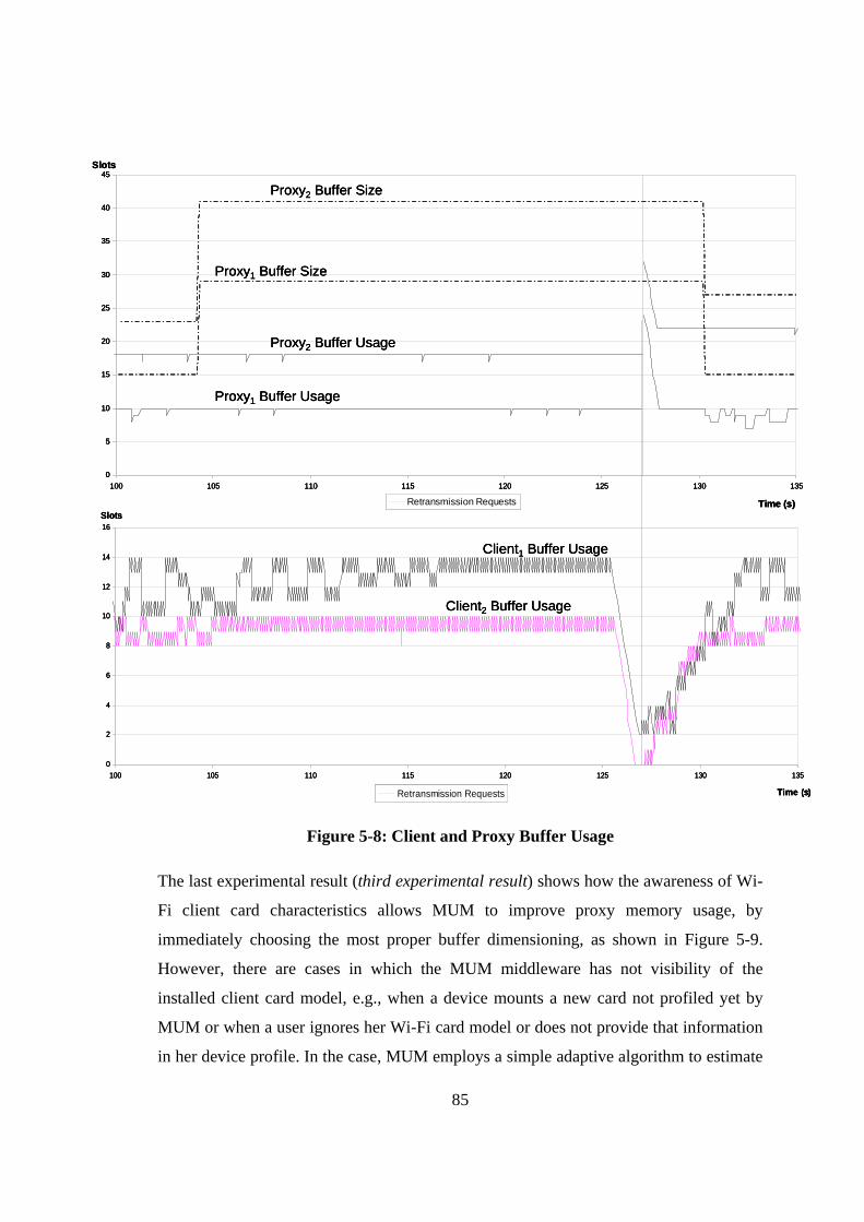
85
0
5
10
15
20
25
30
35
40
45
100 105 110 115 120 125 130 135
Time (s)
Slots
Retransmission Requests
Proxy1 Buffer Usage
Proxy2 Buffer Usage
Proxy1 Buffer Size
Proxy2 Buffer Size
0
2
4
6
8
10
12
14
16
100 105 110 115 120 125 130 135
Time (s)
Slots
Retransmission Requests
Client1 Buffer Usage
Client2 Buffer Usage
0
5
10
15
20
25
30
35
40
45
100 105 110 115 120 125 130 135
Time (s)
Slots
Retransmission Requests
Proxy1 Buffer Usage
Proxy2 Buffer Usage
Proxy1 Buffer Size
Proxy2 Buffer Size
0
5
10
15
20
25
30
35
40
45
100 105 110 115 120 125 130 135
Time (s)
Slots
Retransmission Requests
Proxy1 Buffer Usage
Proxy2 Buffer Usage
Proxy1 Buffer Size
Proxy2 Buffer Size
0
2
4
6
8
10
12
14
16
100 105 110 115 120 125 130 135
Time (s)
Slots
Retransmission Requests
Client1 Buffer Usage
Client2 Buffer Usage
0
2
4
6
8
10
12
14
16
100 105 110 115 120 125 130 135
Time (s)
Slots
Retransmission Requests
Client1 Buffer Usage
Client2 Buffer Usage
Figure 5-8: Client and Proxy Buffer Usage
The last experimental result (third experimental result) shows how the awareness of Wi-
Fi client card characteristics allows MUM to improve proxy memory usage, by
immediately choosing the most proper buffer dimensioning, as shown in Figure 5-9.
However, there are cases in which the MUM middleware has not visibility of the
installed client card model, e.g., when a device mounts a new card not profiled yet by
MUM or when a user ignores her Wi-Fi card model or does not provide that information
in her device profile. In the case, MUM employs a simple adaptive algorithm to estimate
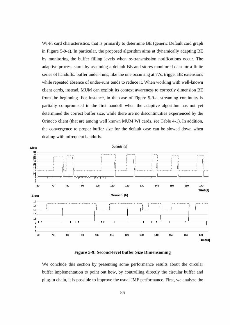
86
Wi-Fi card characteristics, that is primarily to determine BE (generic Default card graph
in Figure 5-9-a). In particular, the proposed algorithm aims at dynamically adapting BE
by monitoring the buffer filling levels when re-transmission notifications occur. The
adaptive process starts by assuming a default BE and stores monitored data for a finite
series of handoffs: buffer under-runs, like the one occurring at 77s, trigger BE extensions
while repeated absence of under-runs tends to reduce it. When working with well-known
client cards, instead, MUM can exploit its context awareness to correctly dimension BE
from the beginning. For instance, in the case of Figure 5-9-a, streaming continuity is
partially compromised in the first handoff when the adaptive algorithm has not yet
determined the correct buffer size, while there are no discontinuities experienced by the
Orinoco client (that are among well known MUM WI cards, see Table 4-1). In addition,
the convergence to proper buffer size for the default case can be slowed down when
dealing with infrequent handoffs.
Orinoco
5
7
9
11
13
15
17
19
60 70 80 90 100 110 120 130 140 150 160 170
Time(s)
Slots
Default
579
1113151719212325272931
60 70 80 90 100 110 120 130 140 150 160 170
Time(s)
Slots Default (a)
Orinoco (b)Orinoco
5
7
9
11
13
15
17
19
60 70 80 90 100 110 120 130 140 150 160 170
Time(s)
Slots
Default
579
1113151719212325272931
60 70 80 90 100 110 120 130 140 150 160 170
Time(s)
Slots
Orinoco
5
7
9
11
13
15
17
19
60 70 80 90 100 110 120 130 140 150 160 170
Time(s)
Slots
Default
579
1113151719212325272931
60 70 80 90 100 110 120 130 140 150 160 170
Time(s)
Slots Default (a)
Orinoco (b)
Figure 5-9: Second-level buffer Size Dimensioning
We conclude this section by presenting some performance results about the circular
buffer implementation to point out how, by controlling directly the circular buffer and
plug-in chain, it is possible to improve the usual JMF performance. First, we analyze the
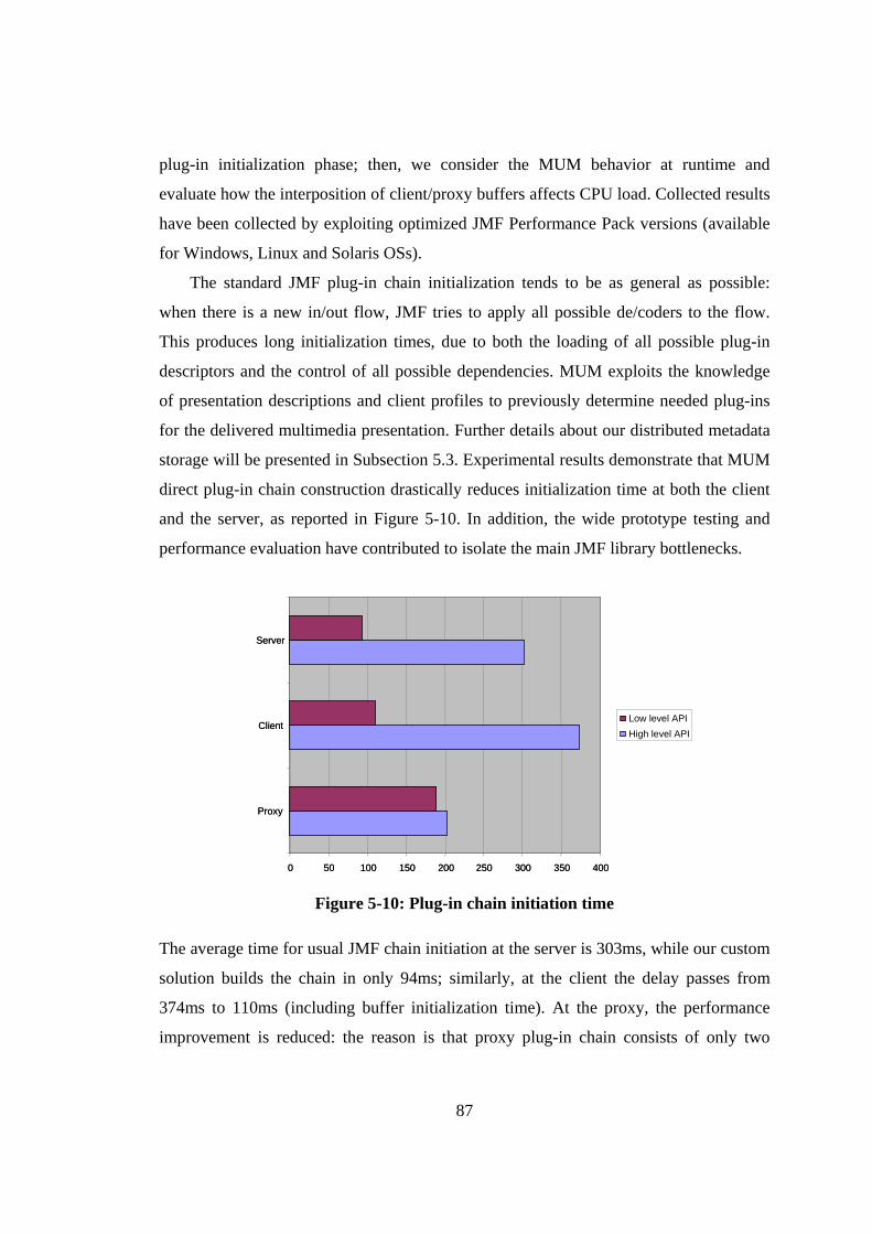
87
plug-in initialization phase; then, we consider the MUM behavior at runtime and
evaluate how the interposition of client/proxy buffers affects CPU load. Collected results
have been collected by exploiting optimized JMF Performance Pack versions (available
for Windows, Linux and Solaris OSs).
The standard JMF plug-in chain initialization tends to be as general as possible:
when there is a new in/out flow, JMF tries to apply all possible de/coders to the flow.
This produces long initialization times, due to both the loading of all possible plug-in
descriptors and the control of all possible dependencies. MUM exploits the knowledge
of presentation descriptions and client profiles to previously determine needed plug-ins
for the delivered multimedia presentation. Further details about our distributed metadata
storage will be presented in Subsection 5.3. Experimental results demonstrate that MUM
direct plug-in chain construction drastically reduces initialization time at both the client
and the server, as reported in Figure 5-10. In addition, the wide prototype testing and
performance evaluation have contributed to isolate the main JMF library bottlenecks.
0 50 100 150 200 250 300 350 400
Proxy
Client
Server
Low level APIHigh level API
0 50 100 150 200 250 300 350 400
Proxy
Client
Server
Low level APIHigh level API
Figure 5-10: Plug-in chain initiation time
The average time for usual JMF chain initiation at the server is 303ms, while our custom
solution builds the chain in only 94ms; similarly, at the client the delay passes from
374ms to 110ms (including buffer initialization time). At the proxy, the performance
improvement is reduced: the reason is that proxy plug-in chain consists of only two
88
stages, since proxies only forward incoming RTP packets to clients, and check neither
packet payload nor plug-in dependencies.
Moreover, we evaluated runtime CPU load by comparing classic JMF and MUM
buffering solutions. Direct plug-in chain programming reduces CPU load from 14,65%
to 11,42% at the server node (Sun Blade 2000 workstations equipped with 900MHz
processors, 1024MB RAM), and from 5,23% to 3,25% at the client (full fledged client
laptops equipped with WindowsXP), while there are no significant improvements at
proxies. Our implementation outperforms JMF at client and server nodes by eliminating
some control threads for either plug-in chain dependences control or plug-in chain state
change notification, e.g., to notify the end of the initialization phase. Proxy plug-in
chains, consisting of only two stages, are less affected by these improvements. In
summary, our two-level buffering outperforms commonly used, JMF-embedded,
buffering mechanisms.
5.2 QoS Management
Guaranteeing session continuity in WI environments is a complex task that requires the
management of several different QoS aspects. Handoff management alone is useless
without proper QoS management of other specific wireless impairments; that is
especially true when dealing with mobile multimedia services given their strict real-time
requisites (see also Subsection 2.2.1). This section describes the Wireless QoS Manager
that is the service gateway mechanism component that manages all those technology-
specific QoS impairments (see Figure 5-1). In particular, we focused our QoS-related
research efforts on Wi-Fi that actually represents one of the most diffused wireless
technologies and we tackled the Wi-Fi performance anomaly problem introduced in
Subsection 2.1.3 [16]. In the following, we will present MUM anomaly management
support: we will first introduce necessary Wi-Fi anomaly background and some related
research efforts; then, we will motivate our context-aware anomaly management
solution. After that, we will describe the internal architecture and we will give
implementation insights about Anomaly Manager – which is part of the wireless QoS
manager – and the Wi-Fi QoS Anomaly Monitor – that enables anomaly-awareness at
89
the middleware level by executing at the client-stub; and finally, we will assess the
performance of the proposed wireless QoS management mechanism.
5.2.1 Wi-Fi Anomaly
The IEEE 802.11 performance anomaly is due to Wi-Fi automatic data rate adaptation
and multiple retransmissions. Nodes located in low coverage areas, called low-rate
stations in the following, cause frequent retransmissions, thus occupying the shared
channel for long time intervals. That reduces the radio resources left to other nodes
attached to the same AP (and thus in the same Basic Service Set - BSS), even if these
nodes are located in good coverage areas, i.e., high-rate stations.
By delving into finer details, all most diffused wireless technologies support
multiple data-link transmission rates, in order to adapt transmissions depending on
wireless channel conditions perceived by wireless stations, i.e., decreasing data-link
frame rate when channel errors increase. In particular, data-link layer adaptation is
usually dominated by the distance between wireless stations and their AP. IEEE 802.11b
supports four data rates, i.e., 11, 5, 2.2, and 1Mbps, and automatically chooses lower
transmission rates as wireless stations move away from APs. In addition, the primary
IEEE 802.11 Medium Access Control (MAC) is Distributed Coordination Function
(DCF) [98]. DCF is based on a Carrier Sense Multiple Access with Collision Avoidance
(CSMA/CA) protocol, designed to be fair and to guarantee the same channel access
opportunities to all stations within the AP cell (clients close/far to/from the AP). DCF
uses multiple retransmissions with positive acknowledgements, and low-rate stations,
given lower experienced link quality, usually require to execute several retransmissions
to successfully deliver MAC frames.
Because of all the above data-link layer aspects (data-link rate adaptation, DCF
fairness, and MAC layer retransmissions), low-rate stations tend to grab the shared
wireless channel for longer times and to decrease the experienced goodput of all other
high-rate nodes in the same BSS. This phenomenon is the so-called IEEE 802.11
performance anomaly.
[48] presents a pioneering work for analysis of the performance anomaly by
showing how all nodes in the same BSS experience the same goodput of the low-rate
90
station. More recently, [96] focuses deeper in the investigation os the anomaly
phenomenon and evaluates the maximum throughput obtainable in a cell with
geographically scattered wireless stations transmitting with different data-link rates. It
also proposes and validates through simulations possible remedies to eliminate anomaly
effects: the guideline is to adaptively change the value of three MAC-layer settings,
namely, initial backoff window, frame size, and maximum backoff stage, depending on
node transmission rate. The main drawback is the need to change the standard IEEE
802.11 MAC layer and to upgrade/re-deploy all existing equipment to support the
modified specification.
[44] and [45] propose a cross-layer approach (across network and MAC layers) not
requiring modifications to IEEE 802.11 specifications. The idea is to avoid anomaly by
providing the AP MAC frame scheduler with full visibility of wireless channel
conditions. Both research efforts employ a similar scheduling technique that differently
weights transmissions to high/low-rate stations: for high-rate nodes, the scheduler
internally accounts the traffic effectively sent over the air; for low-rate ones, the
scheduler accounts for a traffic larger than the one effectively sent, by increasing
transmitted frame lengths depending on channel QoS indications. The main difference
between the two proposals is the adopted wireless monitoring technique: [44] exploits
Signal to Noise Ratio (SNR), while [45] is more precise and monitors the time required
to complete the transmission of each single frame. Both solutions are flexible and enable
per-packet scheduling; however, they present several deployment issues. [44] monitors
SNR at AP by assuming that RSSI values at APs coincide with the corresponding ones at
clients. This imprecision in RSSI evaluations relevantly affects the effectiveness of
anomaly countermeasures. More important, both proposals can be deployed only in
distributed environments with programmable APs, still rare in the consumer market.
Finally, the proposed scheduling techniques introduce new packet scheduling
algorithms, usually implemented at the kernel level, that requires re-compiling operating
system kernels, thus complicating portability and dynamic deployment.
In other words, some first solutions for performance anomaly have been proposed at
low layers of the OSI protocol stack, but application-level solutions are still missing. To
the best of our knowledge, there are only some application-layer solutions tackling
91
partially correlated issues, such as QoS management and service differentiation in
mobile environments [43] or automatic flow adaptation depending on wireless channel
conditions [62], but none of them addresses specifically the IEEE 802.11 performance
anomaly. The following section introduces all main reasons why we consider
application-layer approaches, instead, very relevant for anomaly management in
multimedia streaming applications.
5.2.2 Wi-Fi Anomaly Management: a Context-Aware Approach
The proposed anomaly management mechanism follows the general MUM design
principles (introduced within Chapter 3); hence, it provides full visibility of Wi-Fi
anomaly performance at the middleware layer so to enable proper application-layer
middleware countermeasures.
The long-term optimal solution for the performance anomaly will probably be to
modify the 802.11a/b/g standard specifications. However, a huge number of consumer
802.11a/b/g devices with current IEEE 802.11 DCF are already deployed and will
continue to be available in the market, at least for the next few years. During this long
transition period, application-layer supports are an appealing trade-off to maintain
backward compatibility and to enforce portable and easy-deployable anomaly
countermeasures. Anyway, even if MAC layer was enhanced to avoid the anomaly, the
general problems of adapting delivered flows to actual BSS QoS conditions and of
avoiding service interruption to low-rate stations will remain. In fact, any MAC-layer
anomaly solution tends to preserve high-rate stations at the expense of low-rate node
goodput, i.e., by cutting off low-rate bandwidth.
For all the above reasons, we claim that performance anomaly supports should be
included as a core mechanism in handoff middlewares. In particular, middleware
solutions should be anomaly-aware to take over the responsibility of multimedia flow
adaptation since lower-layer anomaly management solutions could neither take service-
dependent decisions nor perform management operations selectively, e.g., only for
multimedia services.
Moreover, anomaly awareness is also crucial toward proper traffic shaping. In
particular, middlewares should be aware of wireless channel conditions and of
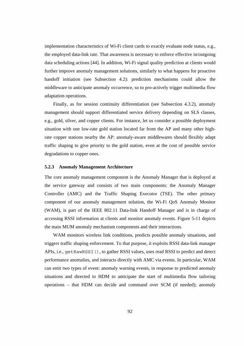
92
implementation characteristics of Wi-Fi client cards to exactly evaluate node status, e.g.,
the employed data-link rate. That awareness is necessary to enforce effective in/outgoing
data scheduling actions [44]. In addition, Wi-Fi signal quality prediction at clients would
further improve anomaly management solutions, similarly to what happens for proactive
handoff initiation (see Subsection 4.2): prediction mechanisms could allow the
middleware to anticipate anomaly occurrence, so to pro-actively trigger multimedia flow
adaptation operations.
Finally, as for session continuity differentiation (see Subsection 4.3.2), anomaly
management should support differentiated service delivery depending on SLS classes,
e.g., gold, silver, and copper clients. For instance, let us consider a possible deployment
situation with one low-rate gold station located far from the AP and many other high-
rate copper stations nearby the AP: anomaly-aware middlewares should flexibly adapt
traffic shaping to give priority to the gold station, even at the cost of possible service
degradations to copper ones.
5.2.3 Anomaly Management Architecture
The core anomaly management component is the Anomaly Manager that is deployed at
the service gateway and consists of two main components: the Anomaly Manager
Controller (AMC) and the Traffic Shaping Executor (TSE). The other primary
component of our anomaly management solution, the Wi-Fi QoS Anomaly Monitor
(WAM), is part of the IEEE 802.11 Data-link Handoff Manager and is in charge of
accessing RSSI information at clients and monitor anomaly events. Figure 5-11 depicts
the main MUM anomaly mechanism components and their interactions.
WAM monitors wireless link conditions, predicts possible anomaly situations, and
triggers traffic shaping enforcement. To that purpose, it exploits RSSI data-link manager
APIs, i.e., getRawRSSI(), to gather RSSI values, uses read RSSI to predict and detect
performance anomalies, and interacts directly with AMC via events. In particular, WAM
can emit two types of event: anomaly warning events, in response to predicted anomaly
situations and directed to HDM to anticipate the start of multimedia flow tailoring
operations – that HDM can decide and command over SCM (if needed); anomaly
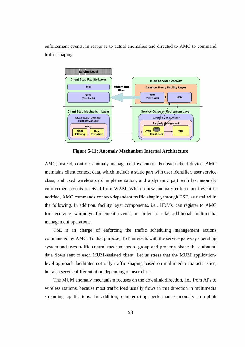
93
enforcement events, in response to actual anomalies and directed to AMC to command
traffic shaping.
Service Level
MCI
Client Stub Mechanism Layer
Client Stub Facility Layer
SCM (Client-side)
IEEE 802.11x Data-link Handoff Manager
WAM
RSSIFiltering
RatePrediction
MUM Service Gateway
Session Proxy Facility Layer
Service Gateway Mechanism Layer
Wireless QoS Manager
Anomaly Management
AMC TSE
MultimediaFlow
Client Data
SCM(Proxy-side) HDM
Service Level
MCI
Client Stub Mechanism Layer
Client Stub Facility Layer
SCM (Client-side)
IEEE 802.11x Data-link Handoff Manager
WAM
RSSIFiltering
RatePrediction
RSSIFiltering
RatePrediction
MUM Service Gateway
Session Proxy Facility Layer
Service Gateway Mechanism Layer
Wireless QoS Manager
Anomaly Management
AMC TSE
MultimediaFlow
Client Data
SCM(Proxy-side) HDM
SCM(Proxy-side) HDM
Figure 5-11: Anomaly Mechanism Internal Architecture
AMC, instead, controls anomaly management execution. For each client device, AMC
maintains client context data, which include a static part with user identifier, user service
class, and used wireless card implementation, and a dynamic part with last anomaly
enforcement events received from WAM. When a new anomaly enforcement event is
notified, AMC commands context-dependent traffic shaping through TSE, as detailed in
the following. In addition, facility layer components, i.e., HDMs, can register to AMC
for receiving warning/enforcement events, in order to take additional multimedia
management operations.
TSE is in charge of enforcing the traffic scheduling management actions
commanded by AMC. To that purpose, TSE interacts with the service gateway operating
system and uses traffic control mechanisms to group and properly shape the outbound
data flows sent to each MUM-assisted client. Let us stress that the MUM application-
level approach facilitates not only traffic shaping based on multimedia characteristics,
but also service differentiation depending on user class.
The MUM anomaly mechanism focuses on the downlink direction, i.e., from APs to
wireless stations, because most traffic load usually flows in this direction in multimedia
streaming applications. In addition, counteracting performance anomaly in uplink
94
direction would require traffic shaping mechanisms also at clients, thus imposing to
install support components and increasing CPU load and power draining at clients.
Performance anomalies due to uplink traffic are rare in most multimedia applications,
thus not justifying the above overheads. For this reason, the current MUM prototype
does not work on uplink anomaly management, even if it could, by installing also TSE
components at served clients.
5.2.4 Anomaly Management Implementation Insights
This subsection describes how QoS management mechanisms perform anomaly
prediction and traffic shaping, which are the two crucial aspects for the effectiveness of
our anomaly-aware solution.
WAM emits a warning event when it predicts that its client is going to pass from a
location where the station can employ high data-link rates (well-covered Wi-Fi areas
with rates of either 11 or 5,5Mbps) to a location where the station has to reduce its rate
(low-covered areas with either 2 or 1Mbps data rates). On the contrary, WAM generates
an anomaly enforcement event when its client actually changes the data rate.
To effectively predict anomaly situations, WAM locally executes a lightweight
procedure including two main steps: i) RSSI filtering to mitigate RSSI fluctuations due
to signal noise, and ii) the application of a hysteresis-based model for data-link rate
prediction based on filtered RSSI values.
The first step of RSSI filtering employs an asymmetric low-pass band filter that
determines the filtered value at discrete time i, indicated as RSSIf(i), depending on the
previous filtered RSSI value at i-1 and on the actual RSSI value at i, indicated as
RSSIa(i): RSSIf(i)=α·RSSIf(i-1)+(1- α)·RSSIa(i)
The value of the smoothing factor α is function of the RSSI evolution trend. In
particular, WAM uses a value α1 when RSSI is increasing, i.e., RSSIa(i)>RSSIf(i-1), and
a smaller value α2 (α2<α1) in case of RSSI decrease. This asymmetry is motivated by
the need to counteract anomalies also when clients are mobile at service provisioning
time. In fact, the different values for α1 and α2 permit to recognize mobile high-rate
stations entering a low-covered area in a very prompt way and, at the same time, to be
less reactive in identifying low-rate nodes (re-)entering a well-covered area. In other
95
words, this asymmetric behavior gives higher priority to the protection of fixed high-rate
stations from possible goodput degradations due to stations moving in border areas, by
promptly penalizing high-rate stations leaving a well-covered area and not immediately
awarding low-rate nodes that are re-entering it.
The second step is made by the data-link rate predictor that, based on filtered RSSI
values, tries to emit correct anomaly notifications in advance with respect to actual
occurrence by exploiting a simple hysteresis-based prediction model. In particular, when
filtered RSSI enters a specified interval, e.g., corresponding to a client positioned in the
area between 5,5 and 2Mbps in the IEEE 802.11b scenario depicted in Figure 5-12, the
middleware triggers a prediction event (anomaly warning). In addition, when the
predictor senses that the client has actually changed its data-link rate, e.g., when the
filtered RSSI value drops below the limit area indicating that the client is actually
located in the 2Mbps coverage area, WAM notifies an anomaly enforcement event. This
event pair is also emitted in the dual situation of a low-rate station moving towards a
better covered area. Let us stress that the network overhead due to anomaly event
notification is limited. WAM fires anomaly events only when clients move and change
their data-link rate, and the adopted filtering/prediction techniques limit event generation
for clients positioned in border areas, as shown by the experimental results in the
following (see Figure 5-15).
Let us rapidly observe that, in order to effectively monitor anomalies in a specific
deployment scenario, WAM requires a preliminary tuning phase to determine proper
values for α1, α2, width and height of each hysteresis in the prediction model (see
Figure 5-12). The proper values of those configuration parameters mainly depend on
implementation peculiarities of Wi-Fi card models used at clients: only the full visibility
of client context, including its employed wireless cards and their behaviors, allows
WAM to achieve optimal middleware performance. For each already profiled wireless
card, MUM stores suitable parameter values at Wireless Card Parameters store and use
them to correctly initialize WAM (see Figure 5-1); for unknown cards, WAM employs a
simple adaptive algorithm that starts assuming default parameter values and iteratively
corrects them according to past anomaly situations, similarly to what happens for
second-level buffer management (see Figure 5-9).
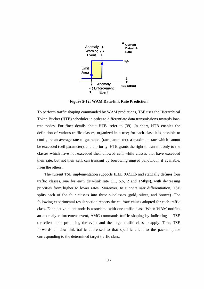
96
RSSI (dBm)
CurrentData-linkRate
LimitArea
AnomalyWarningEvent
AnomalyEnforcement
Event
5,5
2
RSSI (dBm)
CurrentData-linkRate
LimitArea
AnomalyWarningEvent
AnomalyEnforcement
Event
5,5
2
Figure 5-12: WAM Data-link Rate Prediction
To perform traffic shaping commanded by WAM predictions, TSE uses the Hierarchical
Token Bucket (HTB) scheduler in order to differentiate data transmissions towards low-
rate nodes. For finer details about HTB, refer to [39]. In short, HTB enables the
definition of various traffic classes, organized in a tree; for each class it is possible to
configure an average rate to guarantee (rate parameter), a maximum rate which cannot
be exceeded (ceil parameter), and a priority. HTB grants the right to transmit only to the
classes which have not exceeded their allowed ceil, while classes that have exceeded
their rate, but not their ceil, can transmit by borrowing unused bandwidth, if available,
from the others.
The current TSE implementation supports IEEE 802.11b and statically defines four
traffic classes, one for each data-link rate (11, 5.5, 2 and 1Mbps), with decreasing
priorities from higher to lower rates. Moreover, to support user differentiation, TSE
splits each of the four classes into three subclasses (gold, silver, and bronze). The
following experimental result section reports the ceil/rate values adopted for each traffic
class. Each active client node is associated with one traffic class. When WAM notifies
an anomaly enforcement event, AMC commands traffic shaping by indicating to TSE
the client node producing the event and the target traffic class to apply. Then, TSE
forwards all downlink traffic addressed to that specific client to the packet queue
corresponding to the determined target traffic class.
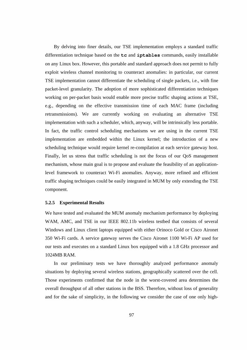
97
By delving into finer details, our TSE implementation employs a standard traffic
differentiation technique based on the tc and iptables commands, easily installable
on any Linux box. However, this portable and standard approach does not permit to fully
exploit wireless channel monitoring to counteract anomalies: in particular, our current
TSE implementation cannot differentiate the scheduling of single packets, i.e., with fine
packet-level granularity. The adoption of more sophisticated differentiation techniques
working on per-packet basis would enable more precise traffic shaping actions at TSE,
e.g., depending on the effective transmission time of each MAC frame (including
retransmissions). We are currently working on evaluating an alternative TSE
implementation with such a scheduler, which, anyway, will be intrinsically less portable.
In fact, the traffic control scheduling mechanisms we are using in the current TSE
implementation are embedded within the Linux kernel; the introduction of a new
scheduling technique would require kernel re-compilation at each service gateway host.
Finally, let us stress that traffic scheduling is not the focus of our QoS management
mechanism, whose main goal is to propose and evaluate the feasibility of an application-
level framework to counteract Wi-Fi anomalies. Anyway, more refined and efficient
traffic shaping techniques could be easily integrated in MUM by only extending the TSE
component.
5.2.5 Experimental Results
We have tested and evaluated the MUM anomaly mechanism performance by deploying
WAM, AMC, and TSE in our IEEE 802.11b wireless testbed that consists of several
Windows and Linux client laptops equipped with either Orinoco Gold or Cisco Aironet
350 Wi-Fi cards. A service gateway serves the Cisco Aironet 1100 Wi-Fi AP used for
our tests and executes on a standard Linux box equipped with a 1.8 GHz processor and
1024MB RAM.
In our preliminary tests we have thoroughly analyzed performance anomaly
situations by deploying several wireless stations, geographically scattered over the cell.
Those experiments confirmed that the node in the worst-covered area determines the
overall throughput of all other stations in the BSS. Therefore, without loss of generality
and for the sake of simplicity, in the following we consider the case of one only high-
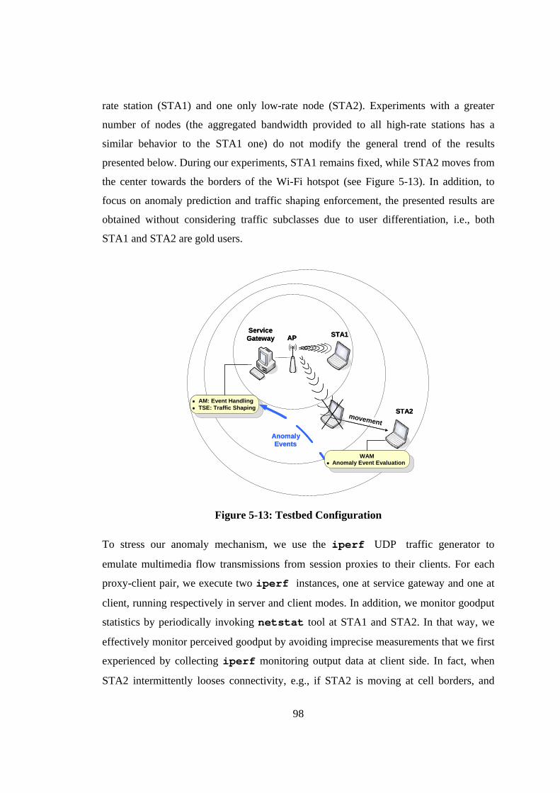
98
rate station (STA1) and one only low-rate node (STA2). Experiments with a greater
number of nodes (the aggregated bandwidth provided to all high-rate stations has a
similar behavior to the STA1 one) do not modify the general trend of the results
presented below. During our experiments, STA1 remains fixed, while STA2 moves from
the center towards the borders of the Wi-Fi hotspot (see Figure 5-13). In addition, to
focus on anomaly prediction and traffic shaping enforcement, the presented results are
obtained without considering traffic subclasses due to user differentiation, i.e., both
STA1 and STA2 are gold users.
AP STA1
• AM: Event Handling• TSE: Traffic Shaping
AnomalyEvents
ServiceGateway
STA2
WAM• Anomaly Event Evaluation
movement
AP STA1
• AM: Event Handling• TSE: Traffic Shaping
AnomalyEvents
ServiceGateway
STA2
WAM• Anomaly Event Evaluation
movementmovement
Figure 5-13: Testbed Configuration
To stress our anomaly mechanism, we use the iperf UDP traffic generator to
emulate multimedia flow transmissions from session proxies to their clients. For each
proxy-client pair, we execute two iperf instances, one at service gateway and one at
client, running respectively in server and client modes. In addition, we monitor goodput
statistics by periodically invoking netstat tool at STA1 and STA2. In that way, we
effectively monitor perceived goodput by avoiding imprecise measurements that we first
experienced by collecting iperf monitoring output data at client side. In fact, when
STA2 intermittently looses connectivity, e.g., if STA2 is moving at cell borders, and
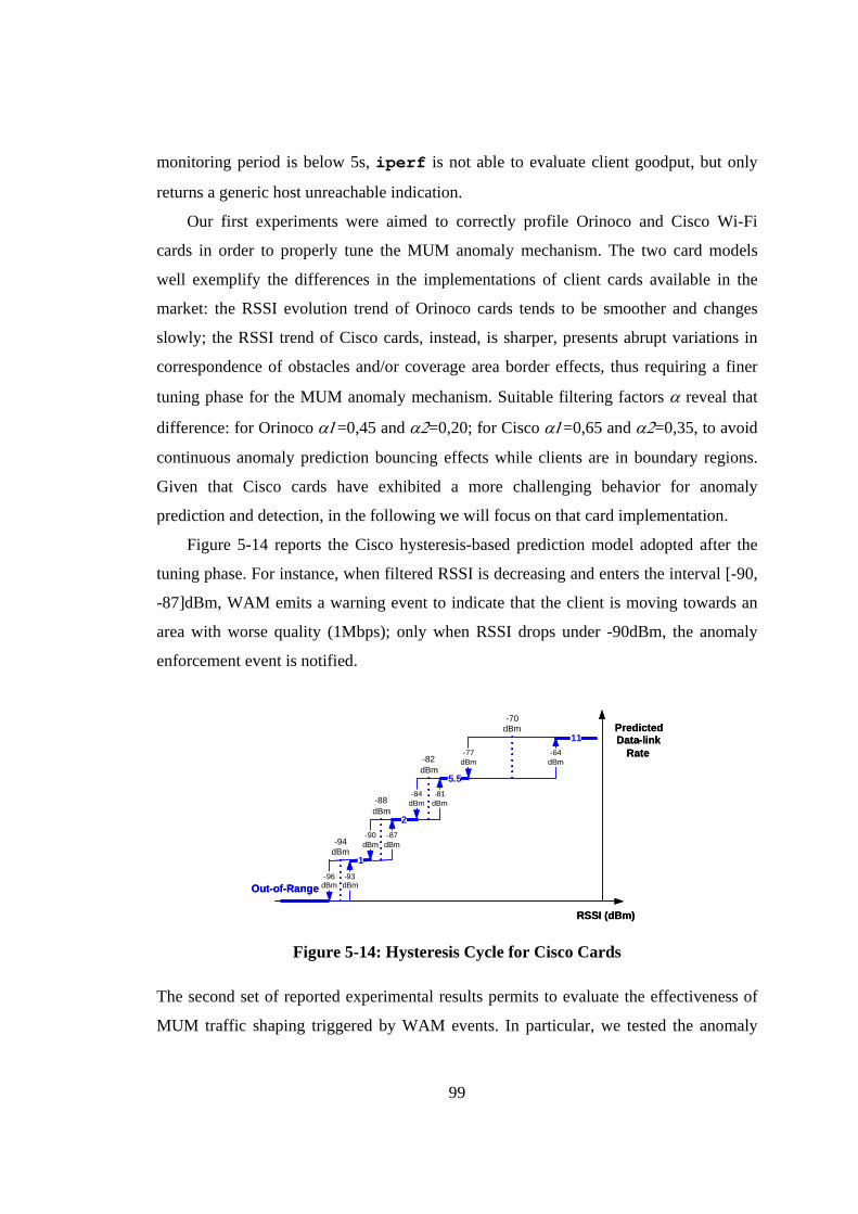
99
monitoring period is below 5s, iperf is not able to evaluate client goodput, but only
returns a generic host unreachable indication.
Our first experiments were aimed to correctly profile Orinoco and Cisco Wi-Fi
cards in order to properly tune the MUM anomaly mechanism. The two card models
well exemplify the differences in the implementations of client cards available in the
market: the RSSI evolution trend of Orinoco cards tends to be smoother and changes
slowly; the RSSI trend of Cisco cards, instead, is sharper, presents abrupt variations in
correspondence of obstacles and/or coverage area border effects, thus requiring a finer
tuning phase for the MUM anomaly mechanism. Suitable filtering factors α reveal that
difference: for Orinoco α1=0,45 and α2=0,20; for Cisco α1=0,65 and α2=0,35, to avoid
continuous anomaly prediction bouncing effects while clients are in boundary regions.
Given that Cisco cards have exhibited a more challenging behavior for anomaly
prediction and detection, in the following we will focus on that card implementation.
Figure 5-14 reports the Cisco hysteresis-based prediction model adopted after the
tuning phase. For instance, when filtered RSSI is decreasing and enters the interval [-90,
-87]dBm, WAM emits a warning event to indicate that the client is moving towards an
area with worse quality (1Mbps); only when RSSI drops under -90dBm, the anomaly
enforcement event is notified.
11
5.5
2
1
-77dBm
-64dBm
RSSI (dBm)
PredictedData-link
Rate
Out-of-Range
-70dBm
-84dBm
-81dBm
-82dBm
-90dBm
-87dBm
-88dBm
-96dBm
-93dBm
-94dBm
11
5.5
2
1
-77dBm
-64dBm
RSSI (dBm)
PredictedData-link
Rate
Out-of-Range
-70dBm
-84dBm
-81dBm
-82dBm
-90dBm
-87dBm
-88dBm
-96dBm
-93dBm
-94dBm
Figure 5-14: Hysteresis Cycle for Cisco Cards
The second set of reported experimental results permits to evaluate the effectiveness of
MUM traffic shaping triggered by WAM events. In particular, we tested the anomaly
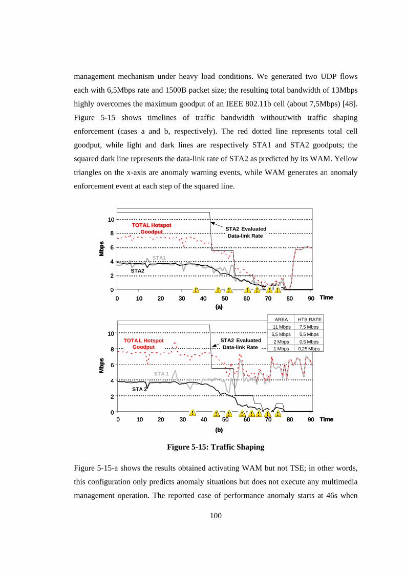
100
management mechanism under heavy load conditions. We generated two UDP flows
each with 6,5Mbps rate and 1500B packet size; the resulting total bandwidth of 13Mbps
highly overcomes the maximum goodput of an IEEE 802.11b cell (about 7,5Mbps) [48].
Figure 5-15 shows timelines of traffic bandwidth without/with traffic shaping
enforcement (cases a and b, respectively). The red dotted line represents total cell
goodput, while light and dark lines are respectively STA1 and STA2 goodputs; the
squared dark line represents the data-link rate of STA2 as predicted by its WAM. Yellow
triangles on the x-axis are anomaly warning events, while WAM generates an anomaly
enforcement event at each step of the squared line.
Mbp
s
(b)
Time
STA 1
STA 2
0
2
4
6
8
10
0 10 20 30 40 50 60 70 80 90
TOTA L Hotspot Goodput
HTB RATE7,5 Mbps5,5 Mbps0,5 Mbps0,25 Mbps
AREA11 Mbps5,5 Mbps2 Mbps1 Mbps
STA2 EvaluatedData-link Rate
Time(a)
STA1
STA2
0
2
4
6
8
10
0 10 20 30 40 50 60 70 80 90
Mbp
s
TOTAL Hotspot Goodput STA2 Evaluated
Data-link Rate
Mbp
s
(b)
Time
STA 1
STA 2
0
2
4
6
8
10
0 10 20 30 40 50 60 70 80 90
TOTA L Hotspot Goodput
HTB RATE7,5 Mbps5,5 Mbps0,5 Mbps0,25 Mbps
AREA11 Mbps5,5 Mbps2 Mbps1 Mbps
STA2 EvaluatedData-link Rate
Mbp
s
(b)
Time
STA 1
STA 2
0
2
4
6
8
10
0 10 20 30 40 50 60 70 80 90
TOTA L Hotspot Goodput
HTB RATE7,5 Mbps5,5 Mbps0,5 Mbps0,25 Mbps
AREA11 Mbps5,5 Mbps2 Mbps1 Mbps
STA2 EvaluatedData-link Rate
STA2 EvaluatedData-link Rate
Time(a)
STA1
STA2
0
2
4
6
8
10
0 10 20 30 40 50 60 70 80 90
Mbp
s
TOTAL Hotspot Goodput STA2 Evaluated
Data-link Rate
Time(a)
STA1
STA2
0
2
4
6
8
10
0 10 20 30 40 50 60 70 80 90
Mbp
s
TOTAL Hotspot Goodput
TOTAL Hotspot Goodput STA2 Evaluated
Data-link RateSTA2 EvaluatedData-link Rate
Figure 5-15: Traffic Shaping
Figure 5-15-a shows the results obtained activating WAM but not TSE; in other words,
this configuration only predicts anomaly situations but does not execute any multimedia
management operation. The reported case of performance anomaly starts at 46s when
101
STA2 enters the 5,5Mbps area; therefore, hotspot goodput begins to drop, without
affecting too much STA1 goodput in this first phase. When STA2 enters the 2Mbps area,
instead, the performance anomaly heavily impacts also on STA1 goodput. Thereafter,
cell goodput continues to degrade until STA2 exits the cell at 79s. The reported results
confirm that the proper setting of WAM parameters permits to effectively filter RSSI by
avoiding bouncing effects notwithstanding the non-negligible fluctuations of both
measured RSSI and data-link rate. In fact, for each rate change, WAM usually emits
only one or two anomaly warning/enforcement events. However, when STA2 is in a
very poorly-covered position, anomaly prediction becomes very challenging and
sometimes produces short event trains, as the one at 72s, that slightly increase the
overhead due to anomaly events. As part of our current work, we are working on
identifying these situations and on evaluating refined prediction solutions with different
values for α settings in these conditions.
In Figure 5-15-b, also TSE is active and uses four traffic classes corresponding to
the four IEEE 802.11b data rates. For each traffic class, ceil is set to the maximum
possible data-link rate, i.e., 7.5, 5.5, 2, and 1Mbps, while rate is set, respectively, to 7.5,
5.5, 0.5 and 0.25Mbps. As shown in the figure, the adopted parameter values permit to
preserve STA1 from anomaly effects: in 11 and 5.5Mbps areas, rate values are equal to
ceils because in those regions anomaly degradations are limited (see Figure 5-15-a). In
poorly-covered areas, instead, it is necessary to highly penalize STA2 to save bandwidth
for STA1. For instance, at 58s the anomaly enforcement event arrives to AMC that
commands TSE to move STA2 to the third traffic class, i.e., to shape outgoing STA2
data flows to 0.5Mbps. That shaping action successfully preserves both STA1 and total
hotspot goodputs.
Finally, by focusing on anomaly event generation, we have measured WAM
processing overhead at client nodes and anomaly warning advance time. The average
result over a wide set of measurements is that the CPU usage increases of about 5% for
polling periods of 1s; that overhead is definitely compatible with computing resources
available on Windows and Linux laptops. With that polling period, WAM can notify
anomaly warning events about 2s-3s in advance with respect to anomaly occurrences,
thus providing enough time to perform also QoS flow downscaling operations at the
102
application level. In particular, this anticipated anomaly awareness is crucial to avoid
flow interruptions towards low-rate stations.
5.3 Dynamic Content Adaptation: the MUM Open Caching Solution
This section will present the MUMOC content adaptation support. MUMOC is an active
infrastructure for distributed caching that significantly extends MUM with the possibility
of support multimedia content dissemination and adaptation efficiently: MUMOC
improves VoD streaming over the best-effort Internet, to primarily support prefix
caching, i.e., the online caching of the initial part of VoD flows at intermediate traversed
service gateway nodes, to allow fast playback startup, i.e., the reduction of user-
perceived VoD startup delays in the case of prefix cache hit in the active infrastructure
(composed by MUM service gateways), and to achieve interoperability, by providing
open and standard representations of the available VoD flows so to simplify the
interworking with legacy VoD systems. In the following, we will first present the usage
scenario that motivated the MUMOC development. Then, we will describe the
Multimedia Content Manager that is the MUM mechanism that enables service gateway
participation to the distributed MUMOC overlay infrastructure. Finally, we will give
some implementation insights about MUMOC profile-based content adaptation and we
will report related experimental results.
5.3.1 MUMOC Overview and Usage Scenario
MUMOC is aimed to support VoD content provisioning towards mobile and resource
constrained client devices (with limited memory, CPU power, frame sizes, …) in WI
environments characterized by high heterogeneity and dynamicity by possibly
decreasing VoD startup time and improving distributed system efficiency via distributed
caching. In particular, the primary idea in MUMOC is to automatically deploy its
caching middleware components – realized as MUM session proxies that coordinate
with the local Multimedia Content Manager available at any service gateway node –
only where needed during provisioning, depending on client location. However, the
caching of whole VoD flows would rapidly exhaust the storage capacity of service
gateway nodes. To overcome that problem, several multimedia cache proposals available
103
in literature usually store only portions of VoD streams at intermediate caching nodes
[52]. Similarly, MUMOC supports the distributed replication and storage of the first few
seconds (prefix) of popular VoD contents at intermediate nodes along client-server
paths. In particular, when a client requires a VoD flow, MUMOC routes the request to
the server, intercepts the incoming VoD flow, and caches its prefix on a proxy node in
the locality currently providing network connectivity to that client. In addition, MUMOC
caches the metadata describing the available VoD contents: a distributed cache
disseminates VoD metadata with the goal of reducing the response time for VoD
retrieval.
Let us introduce the functions of the MUMOC middleware by sketching its
motivating VoD streaming usage scenario, depicted in Figure 5-16. Networked colleges
and libraries in a university campus are interested in collaboratively providing a VoD
streaming service with all the recorded lessons of the last semester. For instance,
imagine that one CS210 lesson has been held in the morning in the engineering college
and stored in the college VoD server. In the afternoon, Bob goes to the central library
and would like to access, from its Wi-Fi laptop, the recorded morning lesson he missed.
Bob’s request produces the streaming of the VoD flow from the engineering college
VoD server to the network locality that currently provides connectivity to Bob’s laptop,
step 1 in the figure. MUMOC not only enables Bob to rapidly find the VoD flow with
the suitable QoS characteristics, but also exploits Bob’s request to operate, as a side
effect of VoD service provisioning, the prefix caching of the lesson at the central library
proxy cache.
Suppose that later in the afternoon Alice goes to the engineering library with her
PDA and asks for the same VoD because she has not well understood some points of the
morning lesson. The MUMOC active middleware can browse metadata describing the
disseminated VoD prefixes and the full VoD flows; MUMOC can discover a node close
to the client, i.e., the central library, that holds a prefix of the requested VoD content, but
with a frame size that is too large for Alice’s limited PDA display. In that case,
MUMOC first commands the prefix downscaling and streaming from the central library
proxy, and possibly activates the caching of the downscaled prefix at the engineering
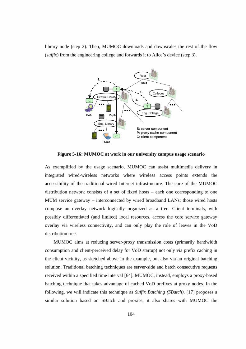
104
library node (step 2). Then, MUMOC downloads and downscales the rest of the flow
(suffix) from the engineering college and forwards it to Alice’s device (step 3).
S: server componentP: proxy cache componentC: client component
Central Library
P
C
Root
Colleges
Eng. College
S
Eng. Library
C
Bob
Alice
1.
1.
2., 3.
3.
S: server componentP: proxy cache componentC: client component
Central LibraryCentral LibraryCentral Library
P
C
RootRoot
CollegesCollegesColleges
Eng. CollegeEng. CollegeEng. College
S
Eng. LibraryEng. LibraryEng. Library
C
BobBob
AliceAlice
1.
1.
2., 3.
3.
Figure 5-16: MUMOC at work in our university campus usage scenario
As exemplified by the usage scenario, MUMOC can assist multimedia delivery in
integrated wired-wireless networks where wireless access points extends the
accessibility of the traditional wired Internet infrastructure. The core of the MUMOC
distribution network consists of a set of fixed hosts – each one corresponding to one
MUM service gateway – interconnected by wired broadband LANs; those wired hosts
compose an overlay network logically organized as a tree. Client terminals, with
possibly differentiated (and limited) local resources, access the core service gateway
overlay via wireless connectivity, and can only play the role of leaves in the VoD
distribution tree.
MUMOC aims at reducing server-proxy transmission costs (primarily bandwidth
consumption and client-perceived delay for VoD startup) not only via prefix caching in
the client vicinity, as sketched above in the example, but also via an original batching
solution. Traditional batching techniques are server-side and batch consecutive requests
received within a specified time interval [64]. MUMOC, instead, employs a proxy-based
batching technique that takes advantage of cached VoD prefixes at proxy nodes. In the
following, we will indicate this technique as Suffix Batching (SBatch). [17] proposes a
similar solution based on SBatch and proxies; it also shares with MUMOC the
105
assumption that, in a general Internet service provisioning scenario, service paths are
usually only unicast-enabled, in contrast with many other batching techniques that
require the ubiquitous availability of multicast support [64].
SBatch activates when a service gateway node receives a request for a prefix stored
locally and, before the prefix streaming to that client ends, it receives requests from
other clients located in the same locality. By referring to the university usage scenario,
suppose that a first request for the CS210 lesson is received by the central library node.
In case of cache hit, the prefix caching node in the client locality immediately starts
streaming the VoD prefix to the client, and properly schedules suffix download from the
server to avoid client-side visualization discontinuity when the prefix terminates. For
successive requests of the same VoD flow from clients in the same locality, SBatch
suggests providing those clients immediately with the locally cached prefix and
anticipating the suffix transmission to them (on a separate channel) as soon as the suffix
starts to be received at the service gateway node. Let us rapidly note that this approach
focuses on reducing transmission costs on the server-service gateway path, by assuming
that local service gateway-client transmission costs are significantly lower, as it is in
wired-wireless integrated networks as the one of the campus-wide streaming scenario.
However, the SBatch solution proposed in [17] requires large storage capacity at client
devices to buffer suffixes and is unsuitable for wired-wireless deployment environments.
The next subsection details the original extensions that MUMOC proposes to the
traditional SBatch strategy.
Finally, MUMOC implements a distributed and replicated VoD metadata repository
both to provide high metadata availability and to reduce the client-perceived delay for
the startup of the requested VoD flow. In fact, VoD metadata are crucial in the MUMOC
middleware: for instance, anytime a client requires a multimedia presentation, MUMOC
looks for the corresponding metadata in the distributed repository to determine where the
VoD flow is available and with which QoS characteristics; VoD metadata are also
exploited to guide service adaptation. Given the frequent usage of VoD metadata in
MUMOC operations, our middleware decides to perform metadata caching potentially at
any wired node of the overlay infrastructure and to maintain a high replication degree for
106
metadata of frequently requested VoD flows, as better explained in the following
subsection.
5.3.2 Multimedia Content Manager Internal Architecture
The MUMOC distributed overlay is enabled at single service gateway hosts by the
Multimedia Content Manager that consists of two main modules: the Content Cache and
Metadata Manager.
Given a multimedia title, description, and possibly hints about the desired VoD
quality, the Metadata Manager (MM) module returns the full metadata about the
available multimedia presentations that match the searching criteria. The module offers
functions for metadata querying, inserting, and deleting. Any MM component locally
hosts a partial replica of XML-based metadata for the available VoD contents and can
coordinate with other distributed MM components to retrieve the needed VoD
description. In particular, MUMOC extend MUM multimedia flow descriptions SLS
(see Subsection 4.3.1) and enable more expressive multimedia content descriptions –
MUMOC metadata – represented according to standard, open, and extensible formats.
The local Content Cache module maintains prefixes at intermediate nodes along the
client-server paths. The module consists of two different components devoted to the
caching of VoD prefixes and to the SBatch enforcement. In particular, MUMOC
supports prefix caching through the interposition of a particular session proxy, called
SBatch Shadow Proxy (SBSP), that operates all necessary prefix caching operations and
extends the base SBatch strategy to support also client devices with limited memory
capabilities (insufficient for suffix buffering) by performing the needed suffix buffering
on behalf of the limited client device in the client vicinity.
In a more detailed view, content cache offers functions for the online VoD prefix
download, enforces VoD prefix replacement strategies, and implements SBatch and the
different original extensions to it proposed in MUMOC. SBSP participates to VoD
caching by exploiting coordinating with the local content cache available at the local
service gateway. In particular, SBSP exploits three main components, as shown in
Figure 5-17: cache manager, transmission scheduler, content downscale, and cache
writer to locally store (downsized) VoD prefixes. In addition, it realizes – as usual (see
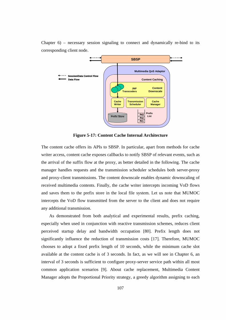
107
Chapter 6) – necessary session signaling to connect and dynamically re-bind to its
corresponding client node.
Multimedia QoS Adaptor
Content CachingSession/Data Control FlowData Flow
CacheManager
CacheWriter
TransmissionScheduler
SBSP
Prefix Store
Pr1Pr2Pr3 Prefix
List
ContentDownscale
JMFTranscoders
Multimedia QoS Adaptor
Content CachingSession/Data Control FlowData Flow
CacheManager
CacheWriter
TransmissionScheduler
SBSP
Prefix Store
Pr1Pr2Pr3
Pr1Pr2Pr3 Prefix
List
ContentDownscale
JMFTranscoders
Figure 5-17: Content Cache Internal Architecture
The content cache offers its APIs to SBSP. In particular, apart from methods for cache
writer access, content cache exposes callbacks to notify SBSP of relevant events, such as
the arrival of the suffix flow at the proxy, as better detailed in the following. The cache
manager handles requests and the transmission scheduler schedules both server-proxy
and proxy-client transmissions. The content downscale enables dynamic downscaling of
received multimedia contents. Finally, the cache writer intercepts incoming VoD flows
and saves them to the prefix store in the local file system. Let us note that MUMOC
intercepts the VoD flow transmitted from the server to the client and does not require
any additional transmission.
As demonstrated from both analytical and experimental results, prefix caching,
especially when used in conjunction with reactive transmission schemes, reduces client
perceived startup delay and bandwidth occupation [80]. Prefix length does not
significantly influence the reduction of transmission costs [17]. Therefore, MUMOC
chooses to adopt a fixed prefix length of 10 seconds, while the minimum cache slot
available at the content cache is of 3 seconds. In fact, as we will see in Chapter 6, an
interval of 3 seconds is sufficient to configure proxy-server service path within all most
common application scenarios [9]. About cache replacement, Multimedia Content
Manager adopts the Proportional Priority strategy, a greedy algorithm assigning to each
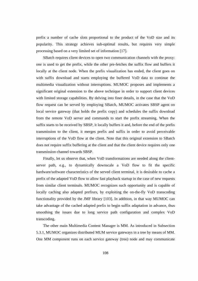
108
prefix a number of cache slots proportional to the product of the VoD size and its
popularity. This strategy achieves sub-optimal results, but requires very simple
processing based on a very limited set of information [17].
SBatch requires client devices to open two communication channels with the proxy:
one is used to get the prefix, while the other pre-fetches the suffix flow and buffers it
locally at the client node. When the prefix visualization has ended, the client goes on
with suffix download and starts employing the buffered VoD data to continue the
multimedia visualization without interruptions. MUMOC proposes and implements a
significant original extension to the above technique in order to support client devices
with limited storage capabilities. By delving into finer details, in the case that the VoD
flow request can be served by employing SBatch, MUMOC activates SBSP agent on
local service gateway (that holds the prefix copy) and schedules the suffix download
from the remote VoD server and commands to start the prefix streaming. When the
suffix starts to be received by SBSP, it locally buffers it and, before the end of the prefix
transmission to the client, it merges prefix and suffix in order to avoid perceivable
interruptions of the VoD flow at the client. Note that this original extension to SBatch
does not require suffix buffering at the client and that the client device requires only one
transmission channel towards SBSP.
Finally, let us observe that, when VoD transformations are needed along the client-
server path, e.g., to dynamically downscale a VoD flow to fit the specific
hardware/software characteristics of the served client terminal, it is desirable to cache a
prefix of the adapted VoD flow to allow fast playback startup in the case of new requests
from similar client terminals. MUMOC recognizes such opportunity and is capable of
locally caching also adapted prefixes, by exploiting the on-the-fly VoD transcoding
functionality provided by the JMF library [103]. In addition, in that way MUMOC can
take advantage of the cached adapted prefix to begin suffix adaptation in advance, thus
smoothing the issues due to long service path configuration and complex VoD
transcoding.
The other main Multimedia Content Manager is MM. As introduced in Subsection
5.3.1, MUMOC organizes distributed MUM service gateways in a tree by means of MM.
One MM component runs on each service gateway (tree) node and may communicate
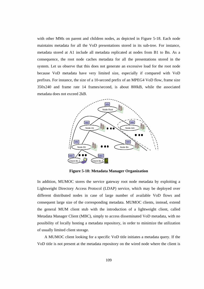
109
with other MMs on parent and children nodes, as depicted in Figure 5-18. Each node
maintains metadata for all the VoD presentations stored in its sub-tree. For instance,
metadata stored at A1 include all metadata replicated at nodes from B1 to Bn. As a
consequence, the root node caches metadata for all the presentations stored in the
system. Let us observe that this does not generate an excessive load for the root node
because VoD metadata have very limited size, especially if compared with VoD
prefixes. For instance, the size of a 10-second prefix of an MPEG4 VoD flow, frame size
350x240 and frame rate 14 frames/second, is about 800kB, while the associated
metadata does not exceed 2kB.
Client B1.1
MBC
Node Root
Node A1 Node Am
Node Bn
MM
MM
MM
MM
MM
Node B1
Client B1.2
MBC
Client B1.1
MBC
Client B1.1Client B1.1
MBC
Node RootNode RootNode Root
Node A1Node A1Node A1 Node AmNode AmNode Am
Node BnNode BnNode Bn
MM
MM
MM
MM
MM
Node B1Node B1Node B1
Client B1.2
MBC
Client B1.2Client B1.2
MBC
Figure 5-18: Metadata Manager Organization
In addition, MUMOC stores the service gateway root node metadata by exploiting a
Lightweight Directory Access Protocol (LDAP) service, which may be deployed over
different distributed nodes in case of large number of available VoD flows and
consequent large size of the corresponding metadata. MUMOC clients, instead, extend
the general MUM client stub with the introduction of a lightweight client, called
Metadata Manager Client (MBC), simply to access disseminated VoD metadata, with no
possibility of locally hosting a metadata repository, in order to minimize the utilization
of usually limited client storage.
A MUMOC client looking for a specific VoD title initiates a metadata query. If the
VoD title is not present at the metadata repository on the wired node where the client is
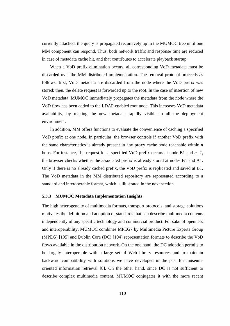
110
currently attached, the query is propagated recursively up in the MUMOC tree until one
MM component can respond. Thus, both network traffic and response time are reduced
in case of metadata cache hit, and that contributes to accelerate playback startup.
When a VoD prefix elimination occurs, all corresponding VoD metadata must be
discarded over the MM distributed implementation. The removal protocol proceeds as
follows: first, VoD metadata are discarded from the node where the VoD prefix was
stored; then, the delete request is forwarded up to the root. In the case of insertion of new
VoD metadata, MUMOC immediately propagates the metadata from the node where the
VoD flow has been added to the LDAP-enabled root node. This increases VoD metadata
availability, by making the new metadata rapidly visible in all the deployment
environment.
In addition, MM offers functions to evaluate the convenience of caching a specified
VoD prefix at one node. In particular, the browser controls if another VoD prefix with
the same characteristics is already present in any proxy cache node reachable within n
hops. For instance, if a request for a specified VoD prefix occurs at node B1 and n=1,
the browser checks whether the associated prefix is already stored at nodes B1 and A1.
Only if there is no already cached prefix, the VoD prefix is replicated and saved at B1.
The VoD metadata in the MM distributed repository are represented according to a
standard and interoperable format, which is illustrated in the next section.
5.3.3 MUMOC Metadata Implementation Insights
The high heterogeneity of multimedia formats, transport protocols, and storage solutions
motivates the definition and adoption of standards that can describe multimedia contents
independently of any specific technology and commercial product. For sake of openness
and interoperability, MUMOC combines MPEG7 by Multimedia Picture Experts Group
(MPEG) [105] and Dublin Core (DC) [104] representation formats to describe the VoD
flows available in the distribution network. On the one hand, the DC adoption permits to
be largely interoperable with a large set of Web library resources and to maintain
backward compatibility with solutions we have developed in the past for museum-
oriented information retrieval [8]. On the other hand, since DC is not sufficient to
describe complex multimedia content, MUMOC conjugates it with the more recent
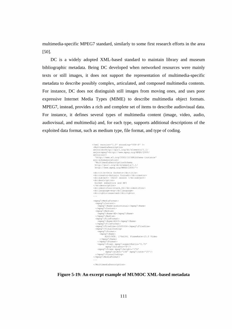
111
multimedia-specific MPEG7 standard, similarly to some first research efforts in the area
[50].
DC is a widely adopted XML-based standard to maintain library and museum
bibliographic metadata. Being DC developed when networked resources were mainly
texts or still images, it does not support the representation of multimedia-specific
metadata to describe possibly complex, articulated, and composed multimedia contents.
For instance, DC does not distinguish still images from moving ones, and uses poor
expressive Internet Media Types (MIME) to describe multimedia object formats.
MPEG7, instead, provides a rich and complete set of items to describe audiovisual data.
For instance, it defines several types of multimedia content (image, video, audio,
audiovisual, and multimedia) and, for each type, supports additional descriptions of the
exploited data format, such as medium type, file format, and type of coding.
<?xml version="1.0" encoding="UTF-8" ?> <MultimediaDescription xmlns:dc=http://purl.org/dc/elements/1.1/ xmlns:mpeg7=http://www.mpeg.org/MPEG/2000/ xmlns:xsi= "http://www.w3.org/2000/10/XMLSchema-instance"
xsi:schemaLocation= "MultimediaDescriptionSchema http://purl.org/dc/elements/1.1/ http://www.mpeg.org/MPEG/2000/">
<dc:title>Unix Sockets</dc:title> <dc:creator>Antonio Corradi</dc:creator> <dc:subject> CS210 lesson </dc:subject> <dc:description> Socket semantics and API </dc:description> <dc:identifier>ntwrk_02</dc:identifier> <dc:language>eng</dc:language> <dc:rights>reserved</dc:rights> ... <mpeg7:MediaFormat> <mpeg7:Content> <mpeg7:Name>audiovisual</mpeg7:Name>
</mpeg7:Content> <mpeg7:Medium> <mpeg7:Name>HD</mpeg7:Name>
</mpeg7:Medium> <mpeg7:FileFormat> <mpeg7:Name>H263</mpeg7:Name>
</mpeg7:FileFormat> <mpeg7:FileSize>12505556</mpeg7:FileSize> <mpeg7:VisualCoding> <mpeg7:Format> <mpeg7:Name>
H263/RTP, 176x144, FrameRate=15.0 Video </mpeg7:Name>
</mpeg7:Format> <mpeg7:Pixel mpeg7:aspectRatio="0.75"
mpeg7:bitsPer="8"/> <mpeg7:Frame mpeg7:height="176"
mpeg7:width="144" mpeg7:rate="15"/> </mpeg7:VisualCoding>
</mpeg7:MediaFormat> ... </MultimediaDescription>
Figure 5-19: An excerpt example of MUMOC XML-based metadata
112
Figure 5-19 reports an example excerpt of MUMOC metadata generated according to the
MUMOC DC-extended schema and describing the multimedia content of a lesson about
“Unix Sockets”. Let us stress the possibility to put together DC and MPEG7 namespace
inclusions, values for the used subset of DC elements (title, creator, …), and MPEG7
Media Format descriptor values. The MPEG7 Media Format descriptor is one of the four
included in the MUMOC DC-extended schema, i.e., Media Locator, Media Time, Media
Format, and Temporal Decomposition. The adoption of open and interoperable metadata
in MUMOC has a twofold objective: first, it simplifies the dynamic selection of the most
suitable one among different versions of the same VoD content with different QoS
levels; second, it facilitates the integration with legacy VoD systems and services, thus
potentially accelerating the acceptance and the diffusion of the MUMOC middleware
proposal.
5.3.4 Experimental Results
The section presents experimental results about MUMOC performance while executing
a simple VoD lesson streaming service, built on top of the MUMOC caching
middleware, in the actual deployment environment of our network lab. We have
considered a usage scenario similar to the one presented in Subsection 5.3.1, where
many students are willing to access VoD flows of registered lessons. Each participating
node hosting the MUMOC middleware may publish VoD contents for downloading
simply by registering them at the MUMOC MM. Client nodes only host a simple
MUMOC-based application client that can look for the requested flow, command its
delivery, and starts playing it as soon as possible during the download.
The used testbed consists of a set of Sun Blade 2000 workstations equipped with a
900 MHz processor and 1024MB RAM and connected by a 100 Mbps Ethernet LAN.
The workstations are equipped with the SunOS 5.9 operating system, the Java Virtual
Machine (JVM) version 1.4.2_03-b02, and exploit the Java Media Framework (JMF)
Performance Pack for Solaris version 2.1.1e as the multimedia streaming library.
Heterogeneous clients with more limited hardware/software capabilities are represented
by full-fledged Asus laptops exploiting IEEE 802.11b connectivity and equipped with
WindowsXP, the same JVM version, and the JMF Performance Pack for Windows. The
113
experiments presented in the following have mainly intended to measure user-perceived
delays in different situations, in order to evaluate the feasibility of the approach and to
quantitatively measure the benefits/overhead due to the MUMOC middleware and, in
particular, to its exploitation of the JMF multimedia streaming library. All reported
results are average values over a set of 100 runs.
In the first experiment, we have disabled all MUMOC caching functions to evaluate
the configuration and activation time of our middleware components for metadata
querying, VoD flow retrieval, and VoD streaming. The average value for the time
interval between the metadata-based VoD flow request and the visualization start at the
client has shown to be 982 ms. This interval has demonstrated to be mainly composed
by: a) video frame activation at the client = 179 ms, b) metadata query = 90 ms, c) SBSP
activation = 179 ms, d) RTP session configuration (including server endpoint signaling
and RTP client creation) = 341 ms, e) player initialization = 121 ms, and f) rendering
initialization = 72 ms. In addition, with MUMOC disabled, we have to play the
downscale time required by JMF libraries to emit the first tailored frame; that time
highly depends on the distance between origin and the target formats; for instance, to
transcode H263 multimedia flows JMF implies about 2s to pass from 352x288 to
176x144 frame sizes, and more than 3s to pass from 352x288 to 128x96 frame sizes. The
second experiment had the objectives of evaluating the MUMOC content cache
activation time and the startup delay increase in the case of activated cache and cache
miss. In this case, the MUMOC signaling and the RTP client/server activation has shown
to be of 339 ms, while the CacheWriter creation requires 46 ms, i.e., that totally amounts
to 385 ms. In the third experiment, we have activated the distributed caching of
MUMOC metadata, by experiencing a startup time increase of about 100 ms per hop in
the distance from the requesting client node to the MM component that maintains
matching metadata (M in the table). When MUMOC MM works, the fixed threshold
measured for service path activation in the first experiment decreases to 938 ms, because
part of that time was due to metadata browsing.
Table 5-1 sums up the average times registered for user-perceived startup delays in
the different situations. Most of the delay is directly related to the low performance of
JMF libraries to create and initialize Java-based processor/player objects, tailor incoming
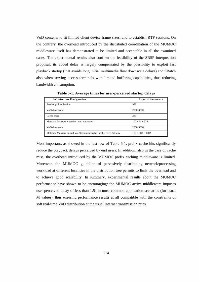
114
VoD contents to fit limited client device frame sizes, and to establish RTP sessions. On
the contrary, the overhead introduced by the distributed coordination of the MUMOC
middleware itself has demonstrated to be limited and acceptable in all the examined
cases. The experimental results also confirm the feasibility of the SBSP interposition
proposal: its added delay is largely compensated by the possibility to exploit fast
playback startup (that avoids long initial multimedia flow downscale delays) and SBatch
also when serving access terminals with limited buffering capabilities, thus reducing
bandwidth consumption.
Table 5-1: Average times for user-perceived startup delays Infrastructure Configuration Required time (msec)
Service path activation 982
VoD downscale 2000-3000
Cache-miss 385
Metadata Manager + service path activation 100 x M + 938
VoD downscale 2000-3000
Metadata Manager on and VoD lesson cached at local service gateway 100 + 982 = 1082
Most important, as showed in the last row of Table 5-1, prefix cache hits significantly
reduce the playback delays perceived by end users. In addition, also in the case of cache
miss, the overhead introduced by the MUMOC prefix caching middleware is limited.
Moreover, the MUMOC guideline of pervasively distributing network/processing
workload at different localities in the distribution tree permits to limit the overhead and
to achieve good scalability. In summary, experimental results about the MUMOC
performance have shown to be encouraging: the MUMOC active middleware imposes
user-perceived delay of less than 1,5s in most common application scenarios (for usual
M values), thus ensuring performance results at all compatible with the constraints of
soft real-time VoD distribution at the usual Internet transmission rates.
115
6. Session Control for Handoff Management
This chapter completes our overview of the MUM handoff middleware by describing
MUM session control management support. The two main goals of this part of the
middleware are: the dynamic reconfiguration and update of all session information
necessary to enable automatic re-negotiation of ongoing sessions when handoffs occur,
and the proactive deployment (and migration) of MUM session proxies, so to follow
client roaming within visited WI localities.
To obtain the first goal, MUM adopts SIP that is widely recognized as the standard
solution to implement session control function for next generation WI networks [24].
However, notwithstanding its wide acceptance, the basic SIP framework does not expose
at the session layer all context information necessary to take advanced session
management decisions, e.g., handoff predictions enabling pro-active redirection/splitting
of streaming flows towards new APs when clients roam in the WI. To bridge that gap,
MUM proposes novel context-aware SIP extensions that add context information
necessary to accomplish advanced session management operations and are fully
compliant with the SIP standard. In addition, MUM employs fast re-addressing
techniques to boost IP re-configuration at the client node.
By focusing on the second goal we claim that session proxies should be mobile and
able to maintain co-locality with their client terminals as they roam during service
sessions, so to automatically re-distribute the service provisioning load within network
access localities. As detailed in Section 6.2, MUM facilitates the dynamic deployment of
session proxy.
The main two components that have been designed and implemented to face the
above issues are FSR and the Session Proxy Manager. FSR is the main session control
component: it cooperates with SCM, especially with the Handoff Executor, to complete
handoff execution by addressing all necessary re-bind operations. The second one is the
Session Proxy Manager that activates and manages the entire MUM session proxy
lifecycle. Figure 6-1 highlights the main components described by this chapter.
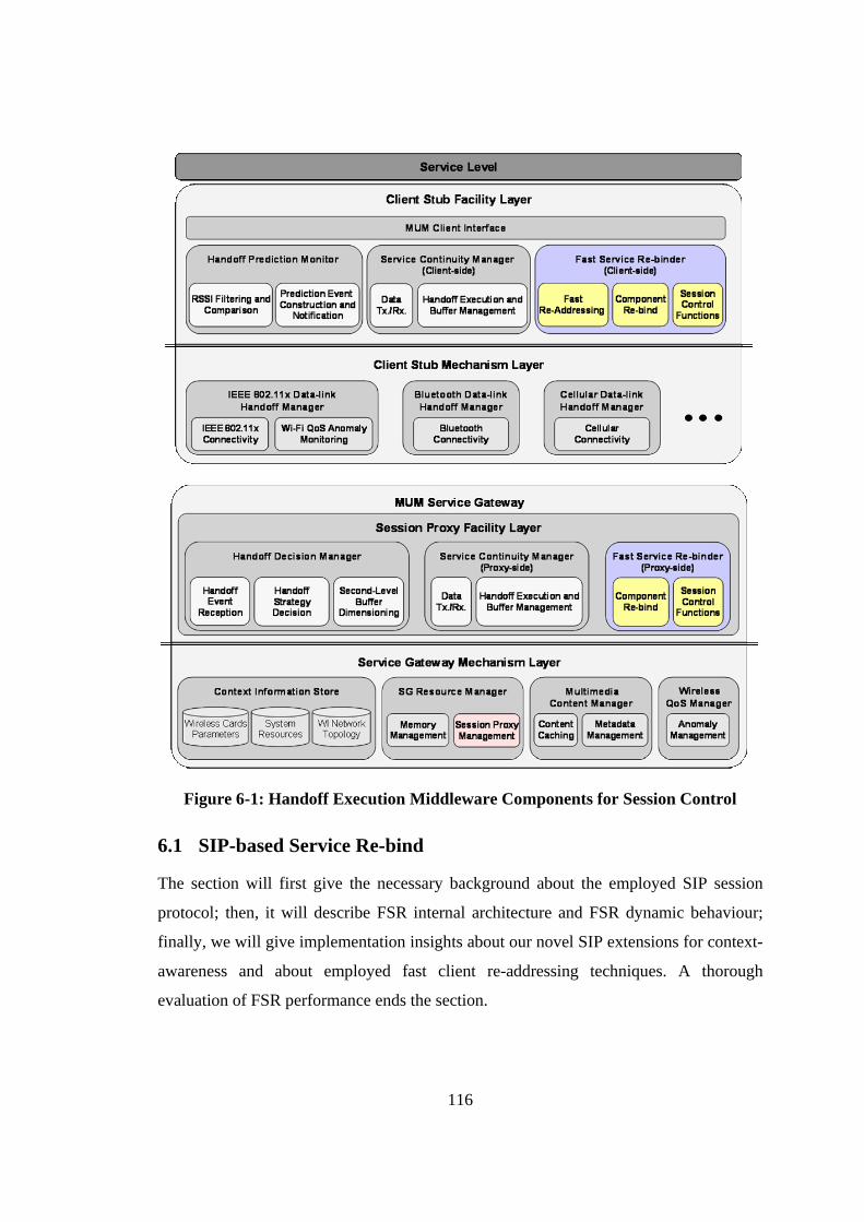
116
Figure 6-1: Handoff Execution Middleware Components for Session Control
6.1 SIP-based Service Re-bind
The section will first give the necessary background about the employed SIP session
protocol; then, it will describe FSR internal architecture and FSR dynamic behaviour;
finally, we will give implementation insights about our novel SIP extensions for context-
awareness and about employed fast client re-addressing techniques. A thorough
evaluation of FSR performance ends the section.
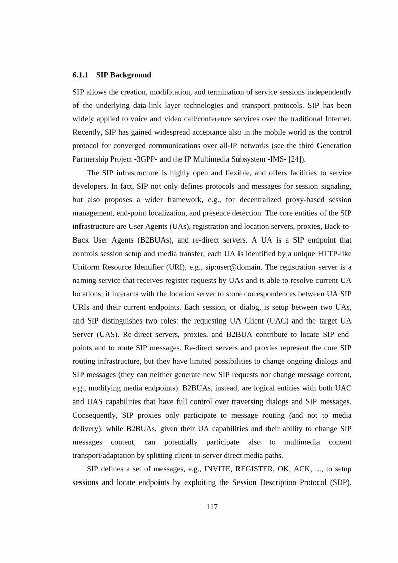
117
6.1.1 SIP Background
SIP allows the creation, modification, and termination of service sessions independently
of the underlying data-link layer technologies and transport protocols. SIP has been
widely applied to voice and video call/conference services over the traditional Internet.
Recently, SIP has gained widespread acceptance also in the mobile world as the control
protocol for converged communications over all-IP networks (see the third Generation
Partnership Project -3GPP- and the IP Multimedia Subsystem -IMS- [24]).
The SIP infrastructure is highly open and flexible, and offers facilities to service
developers. In fact, SIP not only defines protocols and messages for session signaling,
but also proposes a wider framework, e.g., for decentralized proxy-based session
management, end-point localization, and presence detection. The core entities of the SIP
infrastructure are User Agents (UAs), registration and location servers, proxies, Back-to-
Back User Agents (B2BUAs), and re-direct servers. A UA is a SIP endpoint that
controls session setup and media transfer; each UA is identified by a unique HTTP-like
Uniform Resource Identifier (URI), e.g., sip:user@domain. The registration server is a
naming service that receives register requests by UAs and is able to resolve current UA
locations; it interacts with the location server to store correspondences between UA SIP
URIs and their current endpoints. Each session, or dialog, is setup between two UAs,
and SIP distinguishes two roles: the requesting UA Client (UAC) and the target UA
Server (UAS). Re-direct servers, proxies, and B2BUA contribute to locate SIP end-
points and to route SIP messages. Re-direct servers and proxies represent the core SIP
routing infrastructure, but they have limited possibilities to change ongoing dialogs and
SIP messages (they can neither generate new SIP requests nor change message content,
e.g., modifying media endpoints). B2BUAs, instead, are logical entities with both UAC
and UAS capabilities that have full control over traversing dialogs and SIP messages.
Consequently, SIP proxies only participate to message routing (and not to media
delivery), while B2BUAs, given their UA capabilities and their ability to change SIP
messages content, can potentially participate also to multimedia content
transport/adaptation by splitting client-to-server direct media paths.
SIP defines a set of messages, e.g., INVITE, REGISTER, OK, ACK, ..., to setup
sessions and locate endpoints by exploiting the Session Description Protocol (SDP).
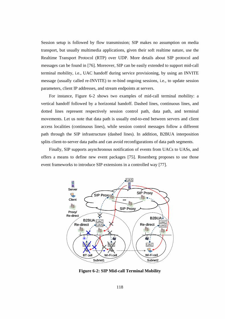
118
Session setup is followed by flow transmission; SIP makes no assumption on media
transport, but usually multimedia applications, given their soft realtime nature, use the
Realtime Transport Protocol (RTP) over UDP. More details about SIP protocol and
messages can be found in [76]. Moreover, SIP can be easily extended to support mid-call
terminal mobility, i.e., UAC handoff during service provisioning, by using an INVITE
message (usually called re-INVITE) to re-bind ongoing sessions, i.e., to update session
parameters, client IP addresses, and stream endpoints at servers.
For instance, Figure 6-2 shows two examples of mid-call terminal mobility: a
vertical handoff followed by a horizontal handoff. Dashed lines, continuous lines, and
dotted lines represent respectively session control path, data path, and terminal
movements. Let us note that data path is usually end-to-end between servers and client
access localities (continuous lines), while session control messages follow a different
path through the SIP infrastructure (dashed lines). In addition, B2BUA interposition
splits client-to-server data paths and can avoid reconfigurations of data path segments.
Finally, SIP supports asynchronous notification of events from UACs to UASs, and
offers a means to define new event packages [75]. Rosenberg proposes to use those
event frameworks to introduce SIP extensions in a controlled way [77].
SIP Proxy
Proxy/Re-direct
Server
ClientSIP Proxy
UAS
SIP Proxy
UAC
Subnet1BT cell Wi-Fi cell
B2BUA UACUAS
UAC
Subnet2
Wi-Fi cell
B2BUAUACUAS
UAC
Re-direct Re-direct
SIP Proxy
Proxy/Re-direct
Server
ClientSIP Proxy
UASUAS
SIP Proxy
UAC
Subnet1BT cell Wi-Fi cell
B2BUA UACUAS
UAC
Subnet2
Wi-Fi cell
B2BUAUACUASUACUAS
UAC
Re-direct Re-direct
Figure 6-2: SIP Mid-call Terminal Mobility
119
Application-layer SIP-based mobility management was first proposed in [79]; thereafter,
a number of SIP-based research efforts tackled session continuity by facing two main
problems: session information re-negotiation and flow continuity. These solutions
propose the exploitation of re-INVITE messages. On the one hand, these messages can
be used to renew SDP parameters and re-negotiate the session, e.g., in an audio/video
conference a client could communicate to UAS its intention to drop the video flow when
it vertically switches from Wi-Fi to 3G. On the other hand, they can be used to update
client address and endpoints, when mobility management is not accomplished at lower
layers of the protocol stack, e.g., if one client does not support MIP.
Several SIP-based research proposals have addressed specifically the second issue
by providing solutions for fast re-binding [78], [92], [70]; nonetheless, in general those
solutions does not guarantee zero packet losses and still incurs in rather long handoff
delays. Other proposals introduce some level of data redundancy to eliminate packet
losses. [37] examines delays introduced by SIP-based vertical handoffs between 3G and
Wi-Fi. Other work from the same group proposes a SIP-based soft-handoff solution to
guarantee low handoff delays and packet losses [5]. During handoffs the client has to
activate more wireless network interfaces, to filter incoming traffic and to drop
duplicated packets; meanwhile, on the network side, a B2BUA is in charge to duplicate
and forward incoming streams to all client network interfaces.
A few proposals, instead, tackle the specific problem of session re-negotiation and
context awareness. IMS uses re-INVITE to re-negotiate ongoing sessions; the main
drawback of this solution is the low expressiveness of SDP parameters [24]. [84]
proposes a more expressive solution based on an event-based package that is used to
dynamically notify the SIP-based infrastructure about client profile and context changes,
e.g., a client change of access network or its entrance in a room.
Let us finally note that all solutions recognize B2BUA interposition as an effective
alternative to traditional client-to-server solutions in the WI. In particular, SIP
distinguishes two proxy types: stateless/stateful proxies support only session signaling,
while B2BUAs support both signaling and streaming control. Hence, active proxies
supporting session continuity also via data retransmission – such as MUM session
proxies – should be implemented as B2BUA proxies in SIP-compliant infrastructures.
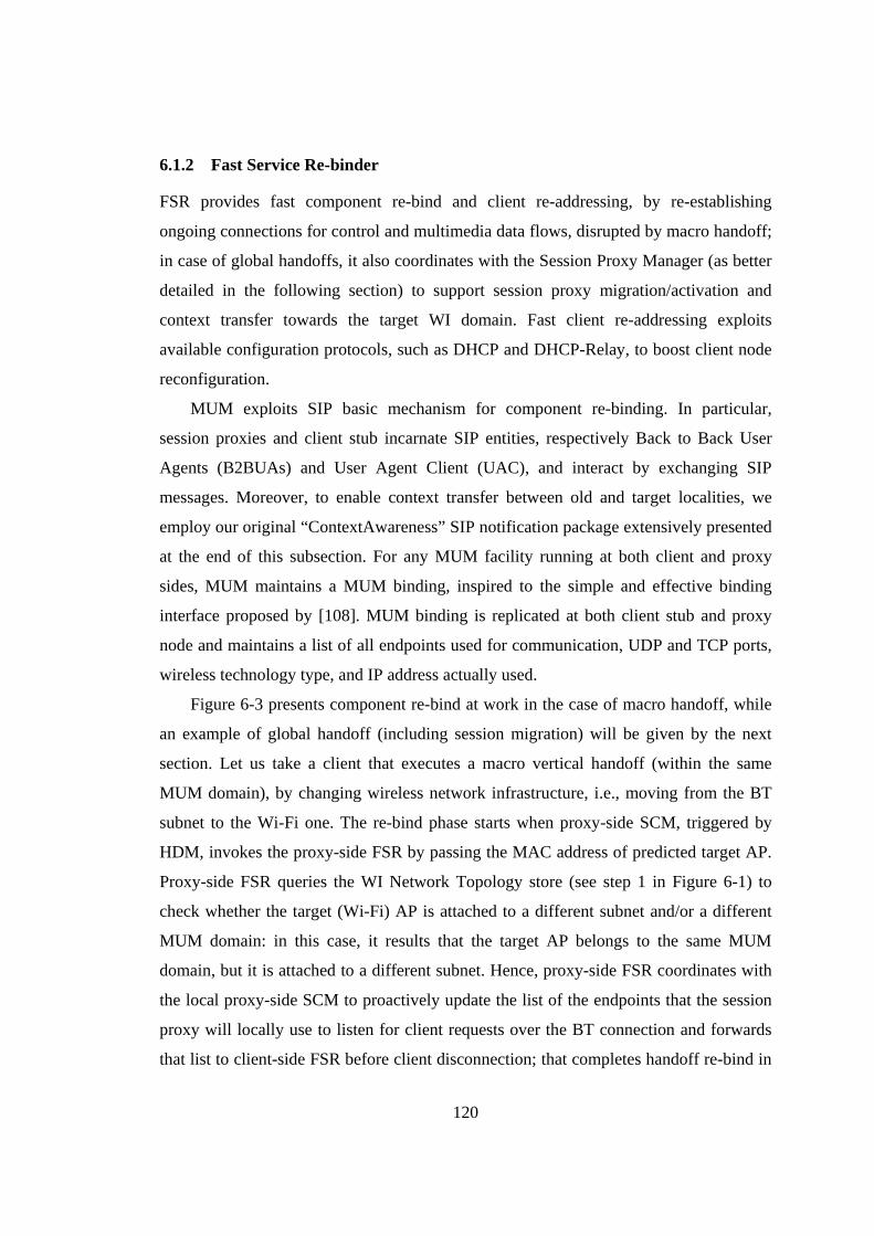
120
6.1.2 Fast Service Re-binder
FSR provides fast component re-bind and client re-addressing, by re-establishing
ongoing connections for control and multimedia data flows, disrupted by macro handoff;
in case of global handoffs, it also coordinates with the Session Proxy Manager (as better
detailed in the following section) to support session proxy migration/activation and
context transfer towards the target WI domain. Fast client re-addressing exploits
available configuration protocols, such as DHCP and DHCP-Relay, to boost client node
reconfiguration.
MUM exploits SIP basic mechanism for component re-binding. In particular,
session proxies and client stub incarnate SIP entities, respectively Back to Back User
Agents (B2BUAs) and User Agent Client (UAC), and interact by exchanging SIP
messages. Moreover, to enable context transfer between old and target localities, we
employ our original “ContextAwareness” SIP notification package extensively presented
at the end of this subsection. For any MUM facility running at both client and proxy
sides, MUM maintains a MUM binding, inspired to the simple and effective binding
interface proposed by [108]. MUM binding is replicated at both client stub and proxy
node and maintains a list of all endpoints used for communication, UDP and TCP ports,
wireless technology type, and IP address actually used.
Figure 6-3 presents component re-bind at work in the case of macro handoff, while
an example of global handoff (including session migration) will be given by the next
section. Let us take a client that executes a macro vertical handoff (within the same
MUM domain), by changing wireless network infrastructure, i.e., moving from the BT
subnet to the Wi-Fi one. The re-bind phase starts when proxy-side SCM, triggered by
HDM, invokes the proxy-side FSR by passing the MAC address of predicted target AP.
Proxy-side FSR queries the WI Network Topology store (see step 1 in Figure 6-1) to
check whether the target (Wi-Fi) AP is attached to a different subnet and/or a different
MUM domain: in this case, it results that the target AP belongs to the same MUM
domain, but it is attached to a different subnet. Hence, proxy-side FSR coordinates with
the local proxy-side SCM to proactively update the list of the endpoints that the session
proxy will locally use to listen for client requests over the BT connection and forwards
that list to client-side FSR before client disconnection; that completes handoff re-bind in
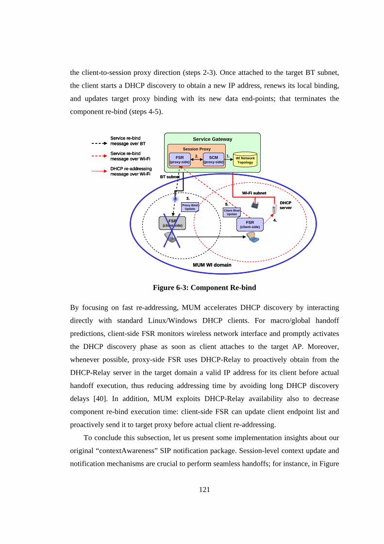
121
the client-to-session proxy direction (steps 2-3). Once attached to the target BT subnet,
the client starts a DHCP discovery to obtain a new IP address, renews its local binding,
and updates target proxy binding with its new data end-points; that terminates the
component re-bind (steps 4-5).
FSR(client-side)
Service re-bind message over BT
Service re-bind message over Wi-Fi
DHCP re-addressing message over Wi-Fi
DHCPserver
Service Gateway
Session Proxy
WI NetworkTopology
BT subnet
Wi-Fi subnet
1.
3.
MUM WI domain
Proxy BindUpdate
FSR(proxy-side)
Client BindUpdate
FSR(client-side)
5.
4.
SCM(proxy-side)
2.
FSR(client-side)
Service re-bind message over BTService re-bind message over BT
Service re-bind message over Wi-FiService re-bind message over Wi-Fi
DHCP re-addressing message over Wi-FiDHCP re-addressing message over Wi-Fi
DHCPserver
Service Gateway
Session Proxy
WI NetworkTopology
BT subnet
Wi-Fi subnet
1.
3.
MUM WI domain
Proxy BindUpdate
FSR(proxy-side)
Client BindUpdate
FSR(client-side)
5.
4.
SCM(proxy-side)
2.
Figure 6-3: Component Re-bind
By focusing on fast re-addressing, MUM accelerates DHCP discovery by interacting
directly with standard Linux/Windows DHCP clients. For macro/global handoff
predictions, client-side FSR monitors wireless network interface and promptly activates
the DHCP discovery phase as soon as client attaches to the target AP. Moreover,
whenever possible, proxy-side FSR uses DHCP-Relay to proactively obtain from the
DHCP-Relay server in the target domain a valid IP address for its client before actual
handoff execution, thus reducing addressing time by avoiding long DHCP discovery
delays [40]. In addition, MUM exploits DHCP-Relay availability also to decrease
component re-bind execution time: client-side FSR can update client endpoint list and
proactively send it to target proxy before actual client re-addressing. To conclude this subsection, let us present some implementation insights about our
original “contextAwareness” SIP notification package. Session-level context update and
notification mechanisms are crucial to perform seamless handoffs; for instance, in Figure
122
6-3 the proxy-side and client-side FSRs, that act respectively as B2BUA and UAC,
exchange SIP notification messages to update MUM bindings; similarly, as we will see
in the next section, old and target session proxies have to all client-related context
information as clients change MUM locality.
NOTIFY sip:[email protected]:3111;transport=udp SIP/2.0 Call-ID: nist-sip-invite-callId 1 CSeq: 5 NOTIFY From: <sip:[email protected]:6102>;tag=7064 To: <sip:[email protected]:3111>;tag=3945 Via: SIP/2.0/UDP 192.168.3.1:6102;branch=z9hG4bK9ad3c15d5... Max-Forwards: 70 Content-Type: application/contextAwarenessinfo+xml Subscription-State: active Event: contextAwareness Content-Length: 473 <?xml version="1.0"?> <!DOCTYPE contextAwareinfo SYSTEM "contextAwarenessinfo.dtd"> <clientinfo xmlns="urn:params:xml:ns:contextAwarenessinfo"> <rebindClient> <SCM> <oldRTP> <address>192.168.2.1</address> <rtpPort>6512</rtpPort> <rtcpPort>6513</rtcpPort> </oldRTP> <newRTP> <address>192.168.2.1</address> <rtpPort>7201</rtpPort> <rtcpPort>7202</rtcpPort> </newRTP> </SCM> ... </rebindClient> </contextAwareinfo>
Figure 6-4: Re-bind NOTIFY message
To solve all above issues, we have defined a MUM event package called
“contextAwareness” that defines the body of all SIP events exchanged between UACs
and B2BUAs. The header of related SUBSCRIBE/NOTIFY SIP messages includes the
package name in the Event field and also the indication of the specific Internet Media
Types (MIME) that must be understood by all contextAwareness event
subscribers/notifiers (application/context-AwarenessInfo+xml).
We have defined an XML schema that describes all possible notification events.
SUBSCRIBE and NOTIFY messages bodies contain XML-expressed events generated
from the defined schema. Figure 6-4 shows the NOTIFY message that updates the client
bindings maintained by the proxy-side FSR (step 5 in Figure 6-3). The event reports, for
each component all necessary re-bind information; for instance, by focusing on SCM,
123
the notify message reports all old and new endpoints used for in/out-coming RTP-over-
UDP connection (by also reporting their relative RTCP ports).
6.1.3 Experimental Results
We have thoroughly tested and evaluated the performance of our SIP-based FSR in a
wireless testbed similar to the one presented above that consists of several Windows and
Linux client laptops equipped with IEEE 802.11b Cisco Aironet 350 Wi-Fi cards and
Mopogo BT dongles (class 1, version 1.1). DHCP servers and B2BUAs execute on
standard Linux boxes with 1.8 GHz processors and 1024MB RAM. Roaming clients
move within our university WI infrastructure served respectively by Mopogo BT
dongles and Cisco Aironet 1100 APs. All SIP entities are implemented in Java, by
exploiting the portable Java API for Integrated Networks (JAIN) SIP implementation by
the National Institute of Standards and Technology (NIST).
The reported results assess two crucial FSR performance indicators: re-addressing
time – which is the basic component of any re-bind phase – and SIP notification time –
in particular, we verified the scalability of the employed JAIN SIP stack –.
By focusing on the first test, in our testbed, DHCP discovery phase lasts 329ms on
the average. We experimentally verified that, by using handoff prediction events to
promptly start DHCP discovery, MUM fast re-addressing drops to 200ms for Linux and
285ms for Windows. In addition, if DHCP-Relay is available at target subnet, re-
addressing time further decreases to network interface configuration time at client
device, i.e., 10-20ms.
The second set of reported experimental results permits to evaluate the prototype
scalability. The JAIN SIP NIST implementation is single-threaded and causes
serialization effects for multiple in/out SIP requests. To tackle the problem, we have
implemented a multi-threaded solution that proactively activates a pool of threads whose
size depends on previous execution history. Each B2BUA has its own thread, while each
re-direct server owns a thread pool to serve incoming requests. In particular, Figure 6-5
reports the delay between the rebind NOTIFY (sent by UAC when re-attaches after
vertical handoff) and OK (sent by B2BUA) messages. The figure shows how the delay
changes by varying client number and request frequency. Request arrival times were
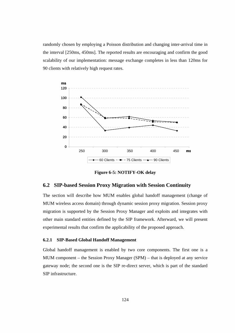
124
randomly chosen by employing a Poisson distribution and changing inter-arrival time in
the interval [250ms, 450ms]. The reported results are encouraging and confirm the good
scalability of our implementation: message exchange completes in less than 120ms for
90 clients with relatively high request rates.
0
20
40
60
80
100
120
1 2 3 4 5
60 Clients 75 Clients 90 Clients
ms
250 300 350 400 450 ms0
20
40
60
80
100
120
1 2 3 4 5
60 Clients 75 Clients 90 Clients
ms
250 300 350 400 450 ms
Figure 6-5: NOTIFY-OK delay
6.2 SIP-based Session Proxy Migration with Session Continuity
The section will describe how MUM enables global handoff management (change of
MUM wireless access domain) through dynamic session proxy migration. Session proxy
migration is supported by the Session Proxy Manager and exploits and integrates with
other main standard entities defined by the SIP framework. Afterward, we will present
experimental results that confirm the applicability of the proposed approach.
6.2.1 SIP-Based Global Handoff Management
Global handoff management is enabled by two core components. The first one is a
MUM component – the Session Proxy Manager (SPM) – that is deployed at any service
gateway node; the second one is the SIP re-direct server, which is part of the standard
SIP infrastructure.
125
If compared with macro handoff, the additional complexity of global handoff is the
possibility and suitability of performing also non-local service path reconfiguration,
possibly up to the server node (SIP UAS). First of all, we do not want to add indirection
point, e.g., for flow re-direction, within the wired Internet core; on the contrary, we want
to deploy middleware components only at wired-wireless network edges. In addition,
MUM has the goal of keeping separated different (MUM) administration domains, to
distribute proxy management responsibilities and to facilitate resource accounting.
Hence, global handoff requires to re-establish the multimedia flow from the target MUM
domain (service gateway) up to the server node. Let us note that global handoff only
requires minimum management between the two domains: the only system management
operation needed is to set logical correspondences between APs in reciprocal visibility at
domain boundaries and service gateway host names (maintained WI Network Topology
store, see Figure 6-1), to enable the correct migration of session proxies to their
destination (service gateway) nodes.
In the following, to better describe how MUM distributed architecture integrates
with standard SIP mobility support (see Subsection 6.1.1), we will employ the SIP
terminology referred to main MUM components. Let us recall that session proxies and
client stub incarnate, respectively, B2BUAs and UAC SIP entities; hence, client stubs
will be referred as UACs and session proxies will be named B2BUAs.
SPM activates and manages the lifecycle of all session proxies executing at the
same MUM domain (service gateway). A SPM can communicate with neighbor SPMs to
activate session proxies in adjacent MUM domains. Re-direct server interacts with SPM
to activate new B2BUAs (session proxies) in response to session initiation requests, and
re-directs clients towards their B2BUAs. MUM does not impose any change or MUM-
specific SIP extensions at the server side: in fact, B2BUA isolates servers from clients
and MUM clients (equipped with our original UAC) can interoperate with any SIP-
compliant UAS. In addition to those SIP entities, MUM exploits standard discovery
mechanisms, i.e., DHCP, to initially retrieve re-direct servers (see the previous section
for more details). In the following, we will present the same example presented in the
previous section (see Figure 6-3), i.e., a vertical hard handoff from BT to Wi-Fi, with the
126
only change that BT and Wi-Fi subnets belong to different MUM domains (global
handoff).
Figure 6-6 shows the MUM global handoff management process. Continuous lines
represent data streams, dashed lines SIP messages, and dotted black ones non-SIP
control messages. Handoff management starts when the HPM notifies the vertical
handoff prediction event to B2BUA (more exactly to HDM, step 1). This message
contains the MAC address of the predicted next AP, and other parameters used by
B2BUA to determine second-level buffer size. At notification reception, B2BUA
exploits the local WI Network Topology store (see Figure 6-1) to check if the predicted
AP is attached to a different MUM domain: in the case, B2BUA requires the local (old)
SPM to contact the (new) SPM requesting the migration of B2BUA there (session proxy
migration). By delving into finer details, the old SPM clones B2BUA (including client
profile, client-related context information, and second-level buffer) and send it to the
new SPM. The new SPM registers B2BUA in the table stored by local re-direct server
with B2BUA-to-UAC correspondences and that terminates B2BUA migration (step 2-3).
While the new B2BUA waits for its UAC, it immediately starts the server re-connection
(with remote UAS) operations to pull the required multimedia flow from the server and,
as soon as data arrives to B2BUA, it merges them within the data contained in the local
second-level buffer cloned from the old B2BUA (step 4).
As usual, when the client is disconnected from the BT AP and not yet re-connected
at the Wi-Fi AP client-side SCM sustain multimedia rendering at the client device (step
5). Once attached to the new subnet, the client starts a DHCP discovery to obtain a new
IP address and the endpoint of the local re-direct server. After that, UAC sends a re-
INVITE message with its new data endpoints to the re-direct server that promptly
forwards the client to the new B2BUA (steps 6, 6’). Thereafter, UAC updates local
B2BUA subscription with the new B2BUA URI and sends to the new B2BUA our Re-
bind NOTIFY message shown in Figure 6-4 (step 7). After receiving the notification, the
new B2BUA, i.e., SCM, retransmits multimedia frames non-received at the client stub
and forwards the merged stream from UAS (step 8). Vertical handoff ends with the
termination of the old B2BUA.
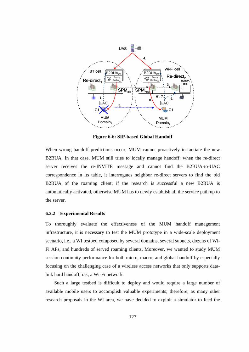
127
BT cell Wi-Fi cell
UAC
Re-direct1
HA1HA1Proxy Buffer
Proxy Buffer
B2BUAC1Proxy
BufferC1
UAC
Re-direct2B2BUA Table
1.
2. 3.
5.
6.6’., 7.
8.
C1 C1
SPMnewSPMold
HA1HA1Proxy Buffer
Proxy Buffer
B2BUAC1Proxy
BufferC1
MUM Domain1
4.
MUM Domain2
UAS
BT cell Wi-Fi cell
UACUAC
Re-direct1
HA1HA1Proxy Buffer
Proxy Buffer
B2BUAC1Proxy
BufferC1
HA1HA1Proxy Buffer
Proxy Buffer
B2BUAC1Proxy
BufferC1
UACUAC
Re-direct2B2BUA Table
1.
2. 3.
5.
6.6’., 7.
8.
C1 C1
SPMnewSPMold
HA1HA1Proxy Buffer
Proxy Buffer
B2BUAC1Proxy
BufferC1
HA1HA1Proxy Buffer
Proxy Buffer
B2BUAC1Proxy
BufferC1
HA1HA1Proxy Buffer
Proxy Buffer
B2BUAC1Proxy
BufferC1
MUM Domain1
4.
MUM Domain2
UAS
Figure 6-6: SIP-based Global Handoff
When wrong handoff predictions occur, MUM cannot proactively instantiate the new
B2BUA. In that case, MUM still tries to locally manage handoff: when the re-direct
server receives the re-INVITE message and cannot find the B2BUA-to-UAC
correspondence in its table, it interrogates neighbor re-direct servers to find the old
B2BUA of the roaming client; if the research is successful a new B2BUA is
automatically activated, otherwise MUM has to newly establish all the service path up to
the server.
6.2.2 Experimental Results
To thoroughly evaluate the effectiveness of the MUM handoff management
infrastructure, it is necessary to test the MUM prototype in a wide-scale deployment
scenario, i.e., a WI testbed composed by several domains, several subnets, dozens of Wi-
Fi APs, and hundreds of served roaming clients. Moreover, we wanted to study MUM
session continuity performance for both micro, macro, and global handoff by especially
focusing on the challenging case of a wireless access networks that only supports data-
link hard handoff, i.e., a Wi-Fi network.
Such a large testbed is difficult to deploy and would require a large number of
available mobile users to accomplish valuable experiments; therefore, as many other
research proposals in the WI area, we have decided to exploit a simulator to feed the
128
MUM prototype with realistic data about client roaming in a modeled wide-scale
deployment scenario. Several wired-network simulators are available, from both
academy and industry; some of them also include wireless network modeling but, to the
best of our knowledge, none addresses the specific problems of simulating different Wi-
Fi card behaviors during handoff and of feeding pluggable software prototypes with
simulation-generated handoff data. Thus, we have decided to develop a simple simulator
that models user mobility and traversed tracks, calculates the RSSI values of mobile
clients, feeds HPM with those values, and mimics physical/data-link/network-layer
behaviors by temporary interrupting streaming transmission during handoffs by using
data-handoff latency values presented in Subsection 4.2.2. The considered WI testbed
consists of 2 Internet domains and 6 subnets with 48 Wi-Fi cells; a mix of 600 wireless
clients equipped with Cisco and Orinoco cards randomly move with variable speed
between 0,6m/s and 1,5m/s; RSSI fluctuation has a 3dB standard deviation.
MUM components are implemented in Java and exploit the portable SUN Java
Media Framework (JMF) for RTP-based video streaming and RTCP-based monitoring;
in the experiments, we have provisioned H263-encoded VoD flows (frame
size=176x144 pixels, and frame rate 8fps). B2BUA migration and activation at new
SPM takes less than 500ms; in addition, experimental results presented in the section
have shown DHCP lasts about 200ms; macro handoff re-bind and RTP re-configuration
requires 300ms in the worst case; global handoff flow reconfiguration (up to UAS)
requires 490ms for RTP streaming activation (with a JMF server) and we assume 350ms
as roundtrip time. In other words, handoff duration is between 440ms and 1500ms for
micro handoff, about 1900ms for macro handoff, and about 2300ms for global handoff.
Among the different experimental results that can provide significant indications
about middleware performance, we evaluated the impact of handoff predictions on our
hard proactive buffer management strategy and, consequently, on the maintenance of
session continuity. To this purpose, we have measured four primary performance
indicators: Efficiency = (PHO/PH)*100, Error = (NPH/PH)*100, Effectiveness =
(SH/PHO)*100, and Continuity = (CV/SH)*100. Predicted Handoffs (PH) is the number
of handoffs foreseen by HPM; Predicted Handoffs Occurred (PHO) is the number of PH
corresponding to actual handoffs in the simulated environment; Non-Predicted Handoffs
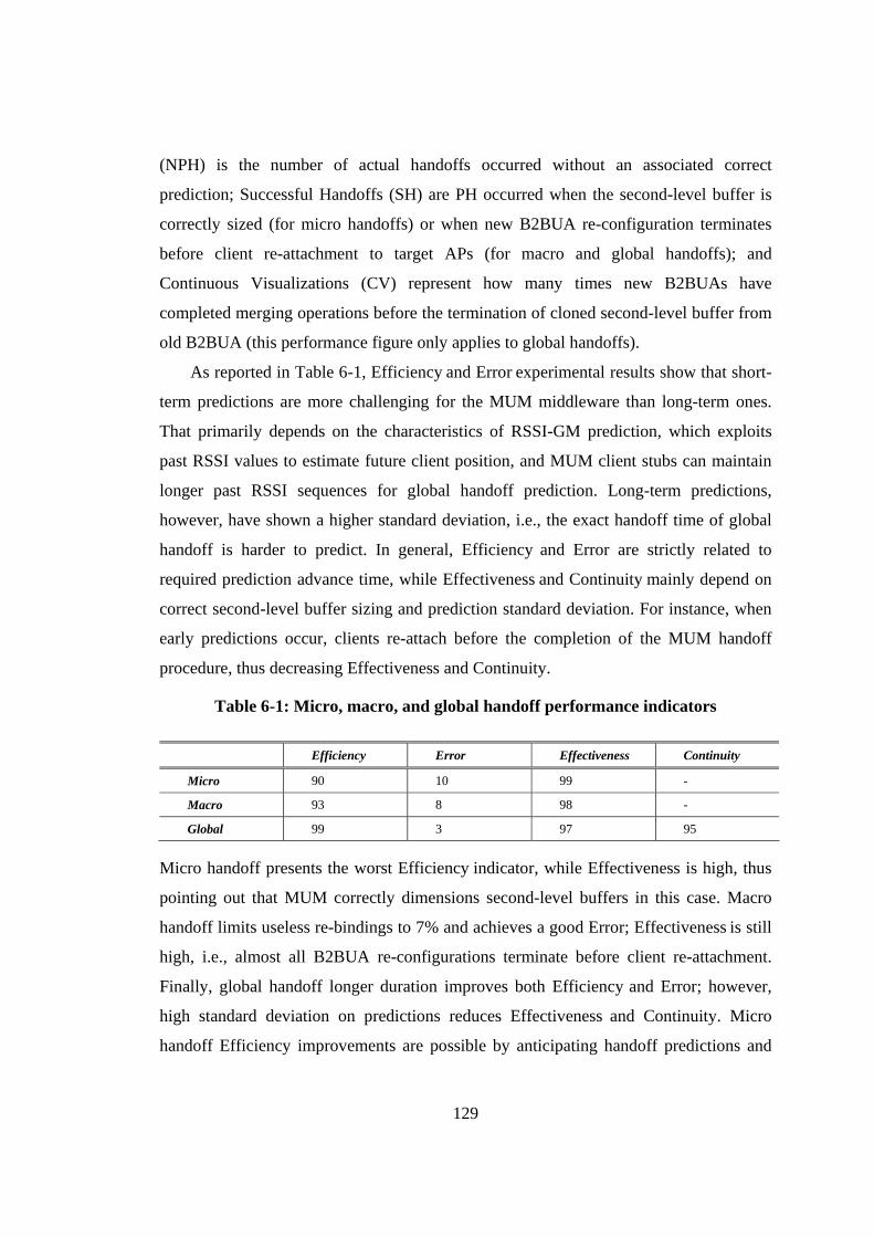
129
(NPH) is the number of actual handoffs occurred without an associated correct
prediction; Successful Handoffs (SH) are PH occurred when the second-level buffer is
correctly sized (for micro handoffs) or when new B2BUA re-configuration terminates
before client re-attachment to target APs (for macro and global handoffs); and
Continuous Visualizations (CV) represent how many times new B2BUAs have
completed merging operations before the termination of cloned second-level buffer from
old B2BUA (this performance figure only applies to global handoffs).
As reported in Table 6-1, Efficiency and Error experimental results show that short-
term predictions are more challenging for the MUM middleware than long-term ones.
That primarily depends on the characteristics of RSSI-GM prediction, which exploits
past RSSI values to estimate future client position, and MUM client stubs can maintain
longer past RSSI sequences for global handoff prediction. Long-term predictions,
however, have shown a higher standard deviation, i.e., the exact handoff time of global
handoff is harder to predict. In general, Efficiency and Error are strictly related to
required prediction advance time, while Effectiveness and Continuity mainly depend on
correct second-level buffer sizing and prediction standard deviation. For instance, when
early predictions occur, clients re-attach before the completion of the MUM handoff
procedure, thus decreasing Effectiveness and Continuity.
Table 6-1: Micro, macro, and global handoff performance indicators
Efficiency Error Effectiveness Continuity
Micro 90 10 99 -
Macro 93 8 98 -
Global 99 3 97 95
Micro handoff presents the worst Efficiency indicator, while Effectiveness is high, thus
pointing out that MUM correctly dimensions second-level buffers in this case. Macro
handoff limits useless re-bindings to 7% and achieves a good Error; Effectiveness is still
high, i.e., almost all B2BUA re-configurations terminate before client re-attachment.
Finally, global handoff longer duration improves both Efficiency and Error; however,
high standard deviation on predictions reduces Effectiveness and Continuity. Micro
handoff Efficiency improvements are possible by anticipating handoff predictions and

130
consequently paying an earlier second-level buffer enlargement, thus trading between
Efficiency and storage overhead at proxies. Let us note that high standard deviation on
predictions risks to produce cases of too late predictions, which also require second-level
buffer refresh (at new B2BUA) to renew obsolete data (sent in the meanwhile to clients
at old B2BUA). To overcome the problem, in global handoff predictions, MUM
commands B2BUAs to continuously refresh the current and new second-level buffers
until clients re-attach.
131
7. Related Work
The distribution of traditional and continuous services over the WI is introducing novel
challenges in service delivery. Hence, in the last decade, a fair amount of research work
has addressed the several different issues that we tackled during this thesis. In the
previous chapters, especially when dealing with specific management aspects, such as
Wi-Fi performance anomaly and SIP extensions for context awareness, we have already
presented related research efforts. In this last chapter, instead, we will focus only on
handoff management-related research works.
In particular, the goal of the chapter is two-fold: on the one hand, it presents main
handoff management research efforts at different OSI protocol stack layers; on the other
hand, it compares our proposal with other existing ones and it employs the comparison
to draw concluding technical remarks about our thesis work and to identify open
technical issues. The organization of the chapter is as follows. The first section surveys
the existing research proposals for handoff management; the second section shows a
detailed evaluation of MUM and other related research efforts; then, the third section
presents technical conclusions and open research issues.
7.1 Handoff Management: Competing Solution at Different Layers
This section classifies most important handoff management work proposed in the
literature: most of them work at lower layers of the OSI protocol stack (datalink,
network, and transport); then, it presents a few application-layer solutions more
extensively for comparison’s sake with MUM. We decided to partition handoff
management solutions accordingly to which OSI layer they belong to: data-link,
network, transport, and application layers (for sake of presentation, we will group
together session and application layer approaches as application layer solutions). Since
solutions can cross-cut various OSI layers, our classification collocates research
activities at the layer that plays the key role in the handoff management process. In
addition, to describe presented research proposals, we will employ the context awareness
taxonomy criteria introduced in Section 3.1. Finally, we will mainly focus on handoff
scenarios with BT and Wi-Fi connectivity technologies.
132
7.1.1 Data-link Layer
Let us preliminarily note that research efforts at data-link, network, and transport
layer aim to improve handoff latency and packet loss through static optimization of low
level parameters (timeouts, number of probes for handoff detection, buffer dimension,
…): those lower-level proposal are forced to statically decide and dimension handoff
countermeasures because they lack application-layer visibility of context handoff
information and service requirements.
At the data-link layer, many research activities have addressed horizontal handoff,
while only a few proposals vertical handoff. Wi-Fi implements hard handoff [98], and
thus excludes the possibility to receive any data during the handoff disconnection period.
[67] and [93] analyze Wi-Fi handoff latency by evaluating handoff detection, target AP
search, and re-association times. The last phase is the fastest (usually a few ms) and is
almost constant for different vendors [67]; the other two phases are longer and vendor-
dependent, since IEEE 802.11 only specifies the mechanisms to implement them, by
leaving unspecified their combination and duration. [67] shows that target AP search
could range from 60ms (for Orinoco cards) to 400ms (for Cisco ones), while [93]
assesses handoff detection duration between 1000ms and 1600ms depending on wireless
card implementation; in the worst case, Wi-Fi micro handoff duration may even last 2s.
Those long handoff latencies and corresponding high packet losses motivated
various research activities to enable session continuity. [93] proposes a reactive
technique that drastically reduces the detection phase to a few ms by counting non-
acknowledged data-link frames. [86] drops decision time to 50ms: it introduces a simple
context information, i.e., a neighbor graph maintaining APs vicinity relations, which is
dynamically transferred to client nodes, thus enabling fast AP search. [32] addresses
packet loss by proposing a reactive handoff approach: it exploits Wi-Fi APs (acting as
mediators) to buffer and re-transmit data-link frames, and extends IEEE 802.11 Inter-
Access Point Protocol (IAPP) to move not only the usual AAA information, but also
buffered data, between the previous and target APs.
BT supports either hard or soft handoffs [20], but its handoff latency is longer than
Wi-Fi due to long BT discovery/scan phases required to search new APs when the signal
degrades. [2] first proposed a BT-based infrastructure called BLUEtooth Public Access
133
(BLUEPAC): BLUEPAC only supports hard handoffs and adopts a reactive approach
that produces long handoff latencies up to 4,0-4,5s. [33] improves BLUEPAC handoff
latency by introducing an intermediary entity that maintains synchronization and
addresses of all BT devices under its control; client can query it to obtain those
information, thus avoiding long client-initiated AP search phases. [28] addresses packet
loss by employing a soft handoff technique that pro-actively re-configures data path by
signaling handoff occurrence from the previous to the target AP.
Finally, [83] investigates the possibility to support vertical handoff (between BT and
Wi-Fi) directly at the data-link layer by introducing a virtual MAC layer to mask vertical
handoff to upper layers. However, that solution does not address at all session
continuity.
7.1.2 Network Layer
Most proposals at the network layer aim at reducing packet loss and improving
handoff latency for MIP [54]. MIP overall latency consists of: handoff latency, i.e., time
to detect handoff, decide target subnet, re-configure client address and re-bind client
node (re-routing packets to the actual foreign net); and client node re-location latency,
i.e., time required to update client IP address at client home agent and correspondent
servers. [82] and [90] represent two pioneering works to improve horizontal and vertical
handoff latencies. [82] realizes micro horizontal handoff for WaveLAN: it proposes
layer2 beacon monitoring for handoff detection and decision, employs WaveLAN APs
as communication mediators, and uses multicast and data buffering at APs to alleviate
packet losses. However, this solution presents some problems: it applies only to data-
link soft handoff infrastructures, e.g., it is not usable with Wi-Fi, requires IP multicast at
all visited subnets, and, consequently, introduces significant network overhead. [90]
extends [82] to support also vertical handoffs: it proposes application-layer beaconing to
detect pro-actively vertical handoffs independently of layer2 technology and employs
doublecast, i.e., multicast towards two or more network infrastructures, to reach both
origin and target APs during vertical handoffs. [90] suffers the same drawbacks as [82];
nonetheless, it confirms the need for handoff-aware solutions by showing that vertical
handoff latency is asymmetric and highly depending on employed wireless technologies.
134
[85] proposes a reactive macro handoff procedure for Wi-Fi that reduces MIP handoff
detection due to foreign agent discovery introducing a mediator, i.e., the data-link layer
caching agent, that maintains recent advertisements from local foreign agents and
promptly replies to mobile clients querying for a valid foreign agent.
[25] and [78] survey a number of micro, macro, and global mobility management
enhancements to MIP. Those research efforts have stimulated a considerable debate in
IETF and resulted in two protocol proposals, i.e., Hierarchical MIP (HMIP) and Fast
Handover for MIP (FMIP), which focus respectively on client node re-location and
handoff latencies [56], [88]. HMIP imposes a hierarchical network management
infrastructure to reduce network signaling due to client re-location. That solution is less
central to the scope of this thesis because it tackles regional-based addressing techniques
that let correspondent nodes quickly reach client node (when far from home) rather than
session continuity; see [88] and [60] for further details. FMIP exploits handoff
awareness, i.e., data-link layer triggers (when available), to pro-actively initiate network
routes and client address re-configuration (before client re-attachment), and to forward
packets potentially lost during the disconnection from origin to target AP. Nonetheless,
similarly to other approaches [25], FMIP is data-link layer agnostic: successive research
efforts had to explore how FMIP interact with specific technologies. For instance,
Seamless MIP (S-MIP) is a FMIP extension for horizontal macro Wi-Fi handoff that
addresses both handoff latency and packet losses [49]. S-MIP uses RSSI monitoring for
handoff detection, introduces a mediator, running on the fixed network, to track mobile
nodes and to decide target APs, pro-actively moves packets from origin to target AP, and
during handoff transitory activates simultaneous multicast (simulcast) to forward
incoming data from the access router to both origin and target APs. However, S-MIP
requires significant modifications both to the mobile device for handoff detection and to
APs, e.g., to realize simulcast.
7.1.3 Transport Layer
First transport layer proposals have focused more on the maintenance of TCP end-
to-end semantics, i.e., avoiding connection disruption and guaranteeing at-most-once
semantics during handoffs, than on session continuity. [65] splits client-to-server TCP
135
connections by introducing a proxy (MSOCKS proxy) to guarantee end-to-end TCP
semantics notwithstanding horizontal and vertical handoffs. TCP-Migrate adopts an end-
to-end approach that supports better host mobility, but requires TCP-Migrate
deployment at both communication ends [87].
More recent approaches focus on the wider goal of session continuity. Handoff
awareness of employed wireless technologies lets [47] adopt two different methods, one
for Wi-Fi and one for GPRS, to detect pro-actively vertical handoffs and to smooth
packet losses via soft handoff techniques. However, [47] requires changing TCP/UDP
protocol stack. [29] is a QoS-aware solution that supports vertical handoff and content
adaptation through proxy interposition and UDP tunneling techniques. In particular, [29]
proposes two adaptation methods, respectively for low-to-high and high-to-low
bandwidth modifications at vertical handoffs, to improve transport-layer handoff
detection time. [30] completes [29] with a smart handoff decision model based on
connectivity costs, link capacity, and power consumption.
7.1.4 Application Layer
Recently, more and more research efforts aim to achieve service continuity at the
application layer with significant and augmenting successful results. We have chosen
four solutions compared with MUM by starting from the farthest proposals to the closest
systems; moreover, we added to other research proposals that like MUM adopt SIP
standard for re-bind.
[40] is a highly interoperable framework for secure and proactive horizontal/vertical
handoff. The adopted handoff-aware solution reduces handoff latencies by operating at
different OSI layers by using DHCP-Relaying for fast re-addressing and reducing
authentication delay through proactive movement of AAA client information. Compared
to MUM, [40] does not propose any original handoff prediction solution and focuses on
reducing handoff latency itself rather than on the wider service continuity goal.
Interactive Mobile Application Session Handoff (iMASH) is one of the first
attempts to provide application-layer support for both horizontal and vertical handoff
[22]. When handoffs occur, iMASH proxies adapt session content to target execution
environment and interact with lightweight client-stubs similarly to MUM client stub.
136
However, iMASH proxies are not able to grant service continuity because they neither
have full visibility of handoff and QoS context information nor realize advanced
buffering solutions.
[61] presents a proactive (client-initiated) handoff solution to overcome packet
losses due to Wi-Fi hard handoff for MIP. It enriches MIP foreign agents with
application-layer buffering and adaptation capabilities and employs a two buffering
technique similar to MUM hard handoff to guarantee service continuity to delay-tolerant
services; nonetheless, [61] lacks context awareness required to correctly re/dimension
used buffers: that produces either waste of resources or discontinuities of multimedia
flow delivery.
[3] is a proactive QoS-aware framework for vertical handoff: it defines a rich
context model, including several parameters such as user and network profiles, and
service requirements; proposes context-aware handoff decision; and adopts a proxy-
based architecture for content adaptation and packet loss. This proposal is context-aware
in the sense of MUM but it focuses more on context management itself rather than on
context-aware service continuity: for instance, experimental evaluation is rather simple
and does not deal with real-world handoff latencies.
Application-layer SIP-based mobility management was first proposed by [79],
which suggests to use the SIP re-INVITE message to re-bind ongoing sessions. [70] is a
reactive SIP-based macro handoff solution for Wi-Fi that exploits aggressive router
selection to reduce network handoff latency; differently from MUM, it adopts a reactive
approach that still incurs in rather long handoff delays, i.e., 420 ms, and does not address
packet loss. To counteract that aspect, other proposals introduce data redundancy: for
instance, [5] proposes to adopt soft vertical handoff to eliminate packet loss though
proxy-interposition. The adopted approach is similar to MUM soft handoff, but
experimental results show that [5] adopts a re-active approach for target network
detection and pays long times for target data path activation, up to 20s, that can easily
disrupt service continuity. Table 7-1 sums up all handoff management solutions sketched
above, analyzed by means of the evaluation criteria proposed in Table 3-1.
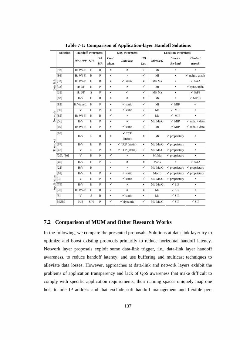
137
Table 7-1: Comparison of Application-layer Handoff Solutions Solution Handoff-awareness QoS-awareness Location-awareness
Dir.: H/V S/H
Det:
P/R
Cont.
adapt.Data loss
HO
Lat. Mi/Ma/G
Service
Re-bind
Context
transf.
[93] H: Wi-Fi H R Mi
[86] H: Wi-Fi H P Mi neigh. graph
[32] H: Wi-Fi H R static Mi/ Ma AAA
[33] H: BT H P Mi sync./addr.
[28] H: BT S P Mi/ Ma IAPP
Dat
a lin
k
[83] H/V H R Mi MPLS
[82] H:WaveL. H P static Mi MIP
[90] V H P static Ma MIP
[85] H: Wi-Fi H R Ma MIP
[56] H/V H P Mi/ Ma/G MIP addr. + dataNet
wor
k
[49] H: Wi-Fi H P static Mi MIP addr. + data
[65] H/V S R
TCP
(static) Mi proprietary
[87] H/V H R TCP (static) Mi/ Ma/G proprietary
[47] V S P TCP (static) Mi/ Ma/G proprietary Tran
spor
t
[29], [30] V H P Mi/Ma proprietary
[40] H/V H P Ma/G AAA
[22] H/V H - Mi/ Ma/G proprietary proprietary
[61] H/V H P static Macro proprietary proprietary
[3] V H P static Mi/ Ma/G proprietary
[79] H/V H P Mi/ Ma/G SIP [70] H: Wi-Fi H R Ma SIP [5] V S R static Ma SIP
App
licat
ion
MUM H/S S/H P dynamic Mi/ Ma/G SIP SIP
7.2 Comparison of MUM and Other Research Works
In the following, we compare the presented proposals. Solutions at data-link layer try to
optimize and boost existing protocols primarily to reduce horizontal handoff latency.
Network layer proposals exploit some data-link trigger, i.e., data-link layer handoff
awareness, to reduce handoff latency, and use buffering and multicast techniques to
alleviate data losses. However, approaches at data-link and network layers exhibit the
problems of application transparency and lack of QoS awareness that make difficult to
comply with specific application requirements; their naming spaces uniquely map one
host to one IP address and that exclude soft handoff management and flexible per-
138
service re-bind; finally, their deployment usually requires protocol stack changes at all
hosts. Transport layer solutions enrich data-link handoff-awareness with per-connection
end-to-end visibility, e.g., bandwidth monitoring/probing, and possibly enable content
adaptation, but that tightly couples transport and application layers [29].
In theory, application layer solutions are more flexible and able to comply with user
and application service requirements. However, most approaches available in the
literature are not able to exploit the potential context visibility for service continuity. In
fact, on the one hand, they mimic lower solutions behaviour at the application layer
without taking advantage of possible full awareness of handoff, QoS, and location: most
of the presented solutions statically dimension packet loss re-transmission buffers [40],
[61], [5]. On the other hand, their focus is shifted more on application issues themselves
— content adaptation and context management — than on service continuity [22], [3].
Compared to the above solutions, MUM proactive session handoff is definitely original
in differentiating service continuity management by exploiting full context awareness to
directly decide among different possible handoff solutions and in performing buffer
dimensioning depending on SLS. Moreover, by choosing the standard RTP for flow
control and SIP for service re-bind, MUM can easily interoperate with other RTP- and
SIP-enabled multimedia streaming systems; in particular, MUM original context-aware
extension to SIP paves the way to open context-aware handoff solutions in WI next
generation networks. Finally, MUM provides its facilities at the application level, thus
enabling its usage in open distributed systems and facilitating the dynamic deployment
of its middleware components.
7.3 Concluding Remarks
In this section, we summarize the main technical contributions of this thesis and address
open issues.
7.3.1 Technical Contribution
As pointed out by the related work section presented above, there are currently no
middleware solutions providing a comprehensive context-aware solution for effective
handoff management that specifically fits the stringent requirements of continuous
139
services. That purpose has led our research work to design a novel handoff middleware
solution – the MUM middleware – for the provisioning of mobile multimedia services
with session continuity guarantees in the WI.
MUM contributed to the state-of-art of the field along several directions: by
recognizing crucial requirements for handoff management, by proposing design
guidelines, and by showing how it is possible to simplify mobile multimedia service
development and deployment through the introduction middleware-level solutions that
could transparently take over and manage all main QoS and session continuity issues.
In particular, this thesis proposed a full context-aware handoff management model.
Context awareness includes full visibility of handoff implementation details, of potential
handoff-related quality degradations, and of client origin/target access localities
(handoff/QoS/location awareness) and enables the transparent execution of proper
handoff management countermeasures at the middleware level. Moreover, this
dissertation sketches clear design guidelines for the development of WI handoff
middleware architectures: they should be developed at the application-layer so to
actively participate to handoff management; they should be pro-active, i.e., able to
evaluate and exploit handoff predict events and to trigger all necessary management
actions in advance so to grant session continuity; and they should adopt a proxy-based
architecture and support both soft and hard handoff management.
The design of the MUM handoff middleware confirmed the feasibility and
applicability of all above guidelines. In fact, MUM application-layer approach enables
modular, flexible, and highly configurable handoff management solutions and permits to
tackle all the main technical handoff-related issues that span several different OSI layers
and include: specific mobile multimedia session continuity requirements, low-level
technological issues (hard/soft data-link handoffs), client mobility and dynamic change
of WI access infrastructure (micro/macro/global and horizontal/vertical handoffs). MUM
provides application-layer visibility of all those aspects at the middleware level and
provides two main handoff management strategies (soft/hard) that can guarantee session
continuity for all main WI handoff management scenarios. Middleware proxies – MUM
session proxies – working over the fixed network on behalf of mobile (and possibly
resource-constrained) clients have demonstrated their suitability and effectiveness in the
140
WI, especially when integrated with WI handoff prediction. In particular, handoff
prediction can help in realizing novel proactive proxy-based infrastructures that perform
adaptive second-level buffering to eliminate/smooth the different discontinuity issues
intrinsic to different handoff situation, even to limited client devices.
By focusing on the MUM implementation, MUM includes all middleware
components necessary to complete all the three main handoff management steps, i.e.,
initiation, decision, and execution. In the following, we detail other core technical
contributions:
• MUM provides a WI handoff prediction monitor that is able to predict and both
horizontal and vertical handoffs, and can interoperate with several different wireless
technologies through convenient middleware components;
• MUM enables differentiated handoff management decisions and simplifies the
specification of service level requirements through the introduction of easy-to-use
SLSs (including the possibility to specify expected service quality through an
objective quality indicator, i.e., VQM indicator);
• MUM supports the execution of both soft and hard handoff management thus
enabling session continuity for a wide range of services – that span from
conversational to streaming services. Especially, it proposes an original adaptive
second-level buffer dimensioning technique for hard handoff to save memory
resource at session proxies;
• MUM proposes original SIP-based extensions to enable open and advanced session
control functions for mobility and handoff management in the WI. MUM integration
with standard mechanisms and protocols, e.g., DHCP-Relay and SIP, is expected to
leverage MUM adoption and to simplify its integration with currently available
multimedia platforms
• MUM includes also other important QoS support facilities (in addition to those
strictly related to handoff management) necessary to grant session continuity in
wireless-enabled environments, such as QoS anomaly management and VoD open
caching functions.
Concerning MUM performance, we have evaluated each single middleware module to
assess its effectiveness, efficiency, and introduced overhead. In general, the reported
141
experimental results demonstrate that our middleware, notwithstanding the flexible
application-level approach, can effectively maintain service continuity in application
deployment environments with the typical QoS requirements of current Internet
streaming, even in the challenging cases of macro and global vertical hard handoffs.
Finally, let us note that MUM application-level middleware approach is portable
and dynamically deployable over the standard WI. Moreover, our handoff management
infrastructure, specifically developed for multimedia streaming, has a general
applicability to any class of WI applications that can benefit from service content pre-
fetching close to client access localities.
7.3.2 Further Investigation Issues
The encouraging results obtained by the MUM prototype implementation are stimulating
further investigation. In particular, actual ongoing research efforts are exploring four
main directions: power management of mobile multimedia services; multimedia content
provisioning within mesh networks; integrated support of other novel wireless
technologies; and handoff management for next generation networks session control
frameworks and protocols, i.e., IP Multimedia Subsystem (IMS).
The first direction is power management. It is well-know that among the
components of a mobile device that contribute to drain battery power the impact of
Wireless Network Interface Cards (WNICs) is widely recognized to be one of the most
relevant. Many energy-efficient solutions have been conceived in the past years; the
most successful solutions are those that identify time intervals for enabling a low power-
consuming state at the client node and periodically switch off the WNIC (or put it in a
sleep mode) during provisioning of a WI application. However, those solutions usually
make the (unrealistic) assumption that wireless nodes do not move for the whole
multimedia session: our research efforts are aimed to remove that assumption and to
optimize existing on/off communication scheduling solutions for power management of
resource-constrained portable devices in presence of handoff.
By focusing on the second one, recent technological advances have motivated the
development of so called wireless mesh networks, i.e., heterogeneous wireless networks
where nodes may play the role of mesh routers and mesh clients: mesh routers wirelessly
142
communicate each other and constitute the backbone of the network; mesh clients
seamlessly roam by dynamically changing their mesh routers. In this scenario, handoff
management represents on of the crucial mesh network support facilities, in particular
when dealing with multimedia service provisioning.
With respect to the third direction, the actual MUM implementation has mainly
focused on BT and Wi-Fi. As a part of our ongoing research efforts, we are actually
realizing new data-link handoff management modules, so provide MUM middleware
facilities also towards other wireless infrastructures, such as UMTS and next generation
WiMax networks.
Finally, the fourth research direction is aimed to study novel solutions and
extensions to improve mobility and handoff management support for actual standard
protocol and framework proposals for multimedia service delivery in next generation
networks, such as IMS. In particular, IMS actually does only partially support
interoperable session handoff and roaming of ongoing calls between different operator
networks and access technologies. To tackle that issue, we are studying a solution based
on the interposition of a special IMS Application Server (AS) that will provide advanced
MUM facilities to any IMS-based service; in a more detailed view, to enable this, we
have to solve security issues related to runtime service roaming and interoperability
issues related to MUM/IMS integration.
143
Conclusions
The convergence between Internet and mobile telecommunications – the Wireless
Internet (WI) – is producing new provisioning scenarios were an increasing variety of
multimedia services with strict QoS requirements are provided to a fast growing market
of users, interconnected by mobile heterogeneous devices.
Even if device and network capabilities are growing, the development of mobile
multimedia services in the WI is still a very complex task due to several factors that may
compromise service continuity, but especially due to WI handoff events.
That complexity mainly stems from high heterogeneity of employed wireless
technologies, spanning from IEEE 802.11 and Bluetooth to cellular 3G, that exhibit very
different handoff behavior due to different data-link layer handoff approaches and from
the high number of competing mobility protocols at network and upper layers, e.g.,
Mobile IP and Session Initiation Protocol. That complexity can be faced up only with the
provision of flexible management facilities and by transferring handoff management
responsibility from the service to the middleware level.
This research work has investigated the design of a middleware for the management
of WI handoff and for the support of service continuity. The proposed MUM
middleware follows the design guideline of exploiting full visibility of handoff
implementation details, of potential handoff-related quality degradations, and of client
origin/target access localities (handoff/QoS/location awareness) to transparently manage
all handoff management aspects at the middleware level. With a closer view to details,
MUM simplifies mobile multimedia services development and deployment by only
requiring the service layer to declare service requirements and obtains service continuity
by exploiting middleware proxies that can execute application-level management
operations via full awareness of handoff context. MUM proxies relieve client/server
application components from complex service adaptation operations by acting
autonomously to assist and support multimedia delivery. In addition, MUM includes a
set of facilities to gather and fuse the data about handoff, QoS, and location for WI
clients; then, MUM proxies exploit those context data to dynamically massage
multimedia provisioning and to grant service continuity to their serving clients.
144
We have realized the middleware components that cooperate to complete
aforementioned handoff management activities. Moreover, we have thoroughly tested
each middleware component to assess the applicability and the overhead of the proposed
approach. In general, the experimental evaluations of MUM have shown that proposed
handoff management solutions can efficiently preserve streaming continuity.
The proposed handoff middleware architecture although specifically optimized for
multimedia streaming, has a general and large applicability to any class of WI
applications that can benefit from service content pre-fetching close to client access
localities. Moreover, MUM application-level approach achieves portability, ease of
deployment, and interoperability with several evolving standards, primarily Session
Initiation Protocol (SIP) and IP Multimedia Subsystem (IMS). For all above reasons, we
are very convinced that this thesis work will have a deep and large impact on service
continuity research and will guide the development of handoff management support
infrastructures for next generation integrated wireless networks.
145
References
[1] C. Aurrecoechea, A.T. Campbell, L. Hauw, A Survey of QoS Architectures, ACM/Springer Multimedia Systems Journal 6 (3) (1998).
[2] S. Baatz, M. Frank, R. Gopffarth, D. Kassatkine, P. Martini, M. Scheteilg, and A. Vilavaara, Handoff support for mobility with IP over Bluetooth, in: Proc. of IEEE Int. Conf. on Local Computer Networks (LCN) (2000).
[3] S. Balasubramaniam, J. Indulska, Vertical Handover Supporting Pervasive Computing in Future Wireless Networks, Elsevier Computer Communication 27 (8) (2004) 708-719.
[4] N. Banerjee, W. Wei, S.K. Das, Mobility support in wireless Internet, IEEE Wireless Communications 10 (5) (2003).
[5] N. Banerjee et al., SIP-based Mobility Architecture for Next Generation Wireless Networks, in: Proc. of IEEE Int. Conf. on Pervasive Computing and Communications (PerCom) (2005).
[6] N. Banerjee, S.K. Das, A. Acharya, Seamless SIP-Based Mobility for Multimedia Applications, IEEE Network 20 (2) (2006).
[7] N. Bartolini, P. Campegiani, E. Casalicchio, Salvatore Tucci, A Performance Study of Context Transfer Protocol for QoS Support, in: Proc. of IEEE/IFIP Int. Symp. on Computer and Information Sciences (ISCIS) (Springer, 2004).
[8] P. Bellavista, A. Corradi, C. Stefanelli, The Ubiquitous Provisioning of Internet Services to Portable Devices, in: IEEE Pervasive Computing 1 (3) (2002).
[9] P. Bellavista, A. Corradi, L. Foschini, MUM: a Middleware for the Provisioning of Continuous Services to Mobile Users, in: Proc. of IEEE International Symposium on Computers and Communications (ISCC) (2004).
[10] P. Bellavista, A. Corradi, L. Foschini, Application-level Middleware to Proactively Manage Handoff in Wireless Internet Multimedia, in: Proc. of IEEE/IFIP Int. Conf. on Management of Multimedia Networks and Services (MMNS) (Spinger, 2005).
[11] P. Bellavista, M. Cinque, D. Cotroneo, L. Foschini, Integrated Support for Handoff Management and Context Awareness in Heterogeneous Wireless Networks, in: Proc. of the Int. Workshop on Middleware for Pervasive Ad-Hoc Computing (MPAC) (ACM Press, 2005).
[12] P. Bellavista, A. Corradi, L. Foschini, MUMOC: an Active Infrastructure for Open Video Caching, in: Proc. of the IEEE Int. Conf. on Distributed Frameworks for Multimedia Applications (DFMA) (2005).
146
[13] P. Bellavista, A. Corradi, L. Foschini, Java-based Proactive Buffering for Multimedia Streaming Continuity in the Wireless Internet, Poster paper in: Proc.of IEEE Int. Symposium on a World of Wireless, Mobile and Multimedia Networks (WoWMoM) (2005).
[14] P. Bellavista, A. Corradi, C. Giannelli, Evaluating Filtering Strategies for Decentralized Handover Prediction in the Wireless Internet, in: Proc. of IEEE Int. Symposium on Computers and Communications (ISCC) (2006).
[15] P. Bellavista, A. Corradi, L. Foschini, Proactive Management of Distributed Buffers for Streaming Continuity in Wired-Wireless Integrated Networks, in: Proc. of IEEE/IFIP Net-work Operations and Management Symposium (NOMS) (2006).
[16] P. Bellavista, A. Corradi, L. Foschini, Context-Aware Multimedia Middleware Solutions for Counteracting IEEE 802.11 Performance Anomaly, Invited Paper to appear in: Proc. of the IEEE Int. Conf. on Multimedia and Ubiquitous Engineering (MUE) (2007).
[17] W. Bing et alii, Optimal proxy cache allocation for efficient streaming media distribution, in: Proc. of IEEE Annual Joint Conference of the IEEE Computer and Communications Societies (INFOCOM) (2002).
[18] G.S. Blair et alii, The Design and Implementation of Open ORB 2, IEEE Distributed Systems Online 2 (6) (2001).
[19] S. Blake et alii, An Architecture for Differentiated Services, IETF RFC 2475 (1998).
[20] Specification of the Bluetooth System - core and profiles v. 1.1, Bluetooth SIG (2001).
[21] R. Braden et alii, Resource ReSerVation Protocol (RSVP), IETF RFC 2205 (1997).
[22] R. Bragodia et alii, iMASH: Interactive Mobile Application Session Handoff, in: Proc. of ACM Int. Conf. on Mobile Systems, Applications, and Services (MobiSys) (2003).
[23] D. Bruneo, M. Villari, A. Zaia, and A. Puliafito, VOD Services for Mobile Wireless Devices, in: Proc. of IEEE Int. Symposium on Computers and Communications (ISCC) (2003).
[24] G. Camarillo et al., The 3G IP Multimedia Subsystem (IMS), Wiley (2005).
[25] A.T. Campbell et alii, Comparison of IP Micromobility Protocols, IEEE Wireless Communications 9 (1) (2002).
[26] C. Casetti et al., TCP westwood: end-to-end congestion control for wired/wireless networks, in: ACM/Kluwer Wireless Networks 8 (5) (2002).
147
[27] D. Chalmers and M. Sloman, A Survey of Quality of Service in Mobile Computing Environments, IEEE Communications Surveys 2 (2) (1999).
[28] M. Chen, J. Chen, P. Yao, Efficient handoff algorithm for Bluetooth networks, in: Proc. of IEEE Int. Conf. on Systems, Man and Cybernetics (2005).
[29] L. Chen, G. Yang, T. Sun, M.Y. Sanadidi, M. Gerla, Enhancing QoS Support for Vertical Handoffs Using Implicit/Explicit Handoff Notifications, in: Proc. of IEEE Int. Conf. on Quality of Service in Heterogeneous Wired/Wireless Networks (QShine) (2005).
[30] L. Chen, T. Sun, B. Chen, V. Rajendran, M. Gerla, A Smart Decision Model for Vertical Handoff, in: Proc. of Int. Work. on Wireless Internet and Reconfigurability (ANWIRE), 2004.
[31] I. Chlamtac, J. J.-N. Liu, Mobile ad hoc networking with a view of 4G wireless: imperatives and challenges, in: Mobile Ad Hoc Networking (eds. Basagni, Conti, Giordano, and Stojmenovic), IEEE Press (2004).
[32] C. Chou, K.G. Shin, An Enhanced Inter-Access Point Protocol for Uniform Intra and Intersubnet Handoffs, in: IEEE Trans. on Mobile Computing 4 (4) (2005).
[33] S. Chung, H. Yoon, J. Cho, A fast handoff scheme for IP over Bluetooth, in: Proc. of IEEE Int. Conf. on Parallel Processing Workshops (ICPPW) (2002).
[34] M. Cinque, D. Cotroneo, and S. Russo. Achieving All the Time, Everywhere Access in Next-Generation Mobile Networks. ACM SIGMOBILE Mobile Computing and Communication Review 9 (2) (2005).
[35] M. Conti, Body, Personal, and Local Ad Hoc Wireless Networks, in: The Handbook of Ad Hoc Wireless Networks (ed. M. Ilyas), CRC Press (2002).
[36] M.S. Corson, J.P. Macker, V.D. Park, Mobile and Wireless Internet Services: Putting the Pieces Together, IEEE Communications Magazine 39 (6) (2001).
[37] S.K. Das, SIP-based vertical handoff between WWANs and WLANs, in: IEEE Wireless Communications 12 (3) (2005).
[38] J.L. Deng, Introduction to Grey Theory, The Journal of Grey System 1 (1) (1989).
[39] M. Devera, Hierarchical Token Bucket home: http://luxik.cdi.cz/~devik/qos/htb/
[40] A. Dutta, T. Zhang, Y. Ohba, K. Taniuchi, H. Schulzrinne, MPA assisted Optimezed Proactive Handoff Scheme, in: Proc. of IEEE Int. Conf. on Mobile and Ubiquitous Systems (MobiQuitous) (2005).
148
[41] A.Dutta et al., Dynamic Buffering Control Scheme for Mobile Handoff, in: Proc. of the IEEE Int. Symposium on Personal, Indoor and Mobile Radio Communications (PIMRC) (2006).
[42] M. Ergen, IEEE 802.11 Tutorial, University of California Berkeley Technical Report (2002). Available online at: http://www.eecs.berkeley.edu/~ergen/docs/ieee.pdf.
[43] J.A. Garcia-Macias et al., Quality of Service and Mobility for the Wireless Internet, in: Springer Wireless Networks Journal 9 (4) (2003).
[44] R.G. Garroppo et al., The Wireless Hierarchical Token Bucket: a Channel Aware Scheduler for 802.11 Networks, in: Proc. of the IEEE Int. Symposium on a World of Wireless Mobile and Multimedia Networks (WoWMoM) (2005).
[45] R. G. Garroppo et al., TWHTB: a Transmission Time Based Channel-Aware Scheduler for 802.11 Systems, in: Proc of Int. Workshop on Resource Allocation in Wireless NETworks (RAWNET) (2005).
[46] D. Grossman, New Terminology and Clarifications for Diffserv, IETF RFC 3260 (2002).
[47] C. Guo, Z. Guo, Q. Zhang, W. Zhu, A Seamless and Proactive End-to-End Mobility Solution for Roaming Across Heterogeneous Wireless Networks, IEEE Jour. on Selected Areas in Communications (JSAC) 22 (5) (2004).
[48] M. Heusse, F. Rousseau, G. Berger-Sabbatel, A. Duda, Performance Anomaly of 802.11b, in: Proc. of IEEE Annual Joint Conference of the IEEE Computer and Communications Societies (INFOCOM) (2003).
[49] R. Hsieh, Z.G. Zhou, A. Seneviratne, S-MIP: a seamless handoff architecture for mobile IP, in: Proc. of IEEE Annual Joint Conference of the IEEE Computer and Communications Societies (INFOCOM) (2003).
[50] J. Hunter, An Application Profile which Combines Dublin Core and MPEG7 Metadata Terms for Simple Video Description, available at: www.metadata.net/harmony/ video_appln_profile.html (2002).
[51] R. Janne, Quality of Service (QoS) concept and architecture, 3GPP Technical Specification (TS) 23.107 (2006).
[52] W.J. Jeon, K. Nahrstedt, QoS-aware middleware support for collaborative multimedia streaming and caching service, in: Elsevier Microprocessors and Microsystems Journal 27 (2) (2003).
[53] J. Jin, K. Nahrstedt, QoS Specification Languages for Distributed Multimedia Applications: A Survey and Taxonomy, IEEE Multimedia Magazine 11 (3) (2004).
149
[54] D. Johnson, C. Perkins, J. Arkko, Mobility Support in IPv6, IETF RFC 3775 (2004).
[55] D.A. Karr, C. Rodrigues, Y. Krishnamurthy, I. Pyarali, J.P. Loyall, R.E. Schantz, D.C. Schmidt, Application of the QuO Quality-of-Service Framework to a Distributed Video Application, in: Proc. of Int. Symposium on Distributed Objects and Applications (DOA) (2001).
[56] R. Koodli, Fast Handovers for Mobile IPv6, IETF RFC 4068 (2005).
[57] M. E. Kounavis and A. T. Campbell, Seamless Connectivity in Infrastructure-based Networks, in: The Handbook of Mobile Middleware (eds. P. Bellavista and A. Corradi), Chapman and Hall, CRC Press (2005).
[58] J. Kristiansson, Java Wireless Research API (JWRAPI), http://www.sm.luth.se/~johank/javawrapi/
[59] T.T. Kwon, M. Gerla, S. Das, Mobility management for VoIP service: Mobile IP vs. SIP, IEEE Wireless Communications 9 (5) (2002) 66-75.
[60] W.K. Lai, J.C. Chui, Improving Handoff Performance in Wireless Overlay Networks by Switching Between Two-Layer IPv6 and One-Layer IPv6 Addressing, in: IEEE Jour. on Selected Areas in Communications (JSAC) 23 (11) (2005).
[61] D. Lee, C. Lee, J.W. Kim, Seamless media streaming over mobile IP-enabled wireless LAN, in: Proc. of the IEEE Consumer Communications and Networking Conference (CCNC) (2005).
[62] Q. Li, M. van der Schaar, Providing Adaptive QoS to Layered Video over Wireless Local Area Networks Through Real-time Retry Limit Adaptation, in: IEEE Trans. on Multimedia 6 (2) (2004).
[63] J. Loughney, M. Nakhjiri, C. Perkins, R. Koodli, Context Transfer Protocol (CXTP), IETF RFC 4067 (2005).
[64] H. Ma, K. G. Shin, Multicast Video-on-Demand services, ACM Computer Communication Review 32 (1) (2002).
[65] D.A. Maltz, P. Bhagwat, MSOCKS: an Architecture for Transport Layer Mobility, in: Proc. of IEEE Annual Joint Conference of the IEEE Computer and Communications Societies (INFOCOM) (1998).
[66] J. McNair, Z. Fang, Vertical handoffs in fourth-generation multinetwork environments, IEEE Wireless Communications 11 (3) (2004).
150
[67] A. Mishra, M. Shin, W. Arbaugh, An Empirical Analysis of the IEEE 802.11 MAC Layer Handoff Process, in: ACM Computer Communication Review 33 (2) (2003) 93-102.
[68] Nader F. Mir, Computer and Communication Networks, Prentice Hall (2006).
[69] K. Nahrstedt, D.Wichadakul, X. Gu, D. Xu, 2Kq+: An Integrated Approach of QoS Compilation and Reconfigurable, Component-Based Run-Time Middleware for Unified QoS Management Framework, in: Proc. of IFIP/ACM Int. Conf. on Distributed Systems Platforms (Middleware) (2001).
[70] N. Nakajima, A. Dutta, S. Das, H. Schulzrinne, Handoff delay analysis and measurement for SIP based mobility in IPv6, in: Proc. of IEEE Int. Conf. on Communications (ICC) (2003).
[71] J. Ott et al., Extended RTP Profile for RTCP-based Feedback (RTP/AVPF), IETF RFC 4585 (2006).
[72] K. Pahlavan et alii, Handoff in hybrid mobile data networks, in: IEEE Personal Communications 7 (2) (2000).
[73] P. Ramanathan, K.M. Sivalingam, P. Agrawal, and S. Kishore, Dynamic Resource Allocation Schemes during Handoff for Mobile Multimedia Wireless Networks, in: IEEE Journal on Selected Areas in Communications (JSAC) 17 (7) (1999).
[74] J. Rey et al., RTP Retransmission Payload Format, IETF RFC 4588 (2006).
[75] A. B. Roach, Session Initiation Protocol (SIP)-Specific Event Notification, IETF RFC 3265, 2002.
[76] J. Rosenberg et al., SIP: Session Initiation Protocol, IETF RFC 3261 (2002).
[77] J. Rosenberg, The Session Initiation Protocol (SIP) INFO Method Considered Harmful, IETF draft-rosenberg-sip-info-harmful-00, 2003.
[78] D. Saha et al., Mobility Support in IP: a Survey of Related Protocols, in: IEEE Network, 18 (6) (2004) 34-40.
[79] H. Schulzrinne, E. Wedlund, Application-layer mobility using SIP, in: ACM Mobile Computing and Communications Review 4 (3) (2000).
[80] S. Sen, J. Rexford, D. Towsley, Proxy prefix caching for multimedia streams, in: Proc. of IEEE Annual Joint Conference of the IEEE Computer and Communications Societies (INFOCOM) (1999).
[81] H. Schulzrinne et al., RTP: A Transport Protocol for Real-Time Applications, IETF RFC 3550 (2003).
151
[82] S. Seshan, H. Balakrishnan, R.H. Katz, Handoffs in Cellular Wireless Networks: The Daedalus Implementation and Experience, in: Kluwer Wireless Personal Communications 4 (2) (1997).
[83] K. Sethom, H. Afifi, Requirements and adaptation solutions for transparent handover between Wifi and Bluetooth, in: Proc. of IEEE Int. Conf. on Communications (ICC) (2004).
[84] R. Shacham et al., An Architecture for Location-based Service Mobility Using the SIP Event Model, in: Proc. of ACM Int. Conf. on Mobile Systems, Applications, and Services (MobiSys) (2004).
[85] S. Sharma, N. Zhu, T. Chiueh, Low-Latency Mobile IP Handoff for Infrastructure-Mode Wireless LANs, in: IEEE Jour. on Selected Areas in Communications (JSAC) 23 (11) (2005).
[86] M. Shin, A. Mishra, W.A. Arbaugh, Improving the Latency of 802.11 Hand-offs using Neighbor Graphs, in: Proc. of ACM Int. Conf. on Mobile Systems, Applications, and Services (MobiSys) (2004).
[87] A.C. Snoeren, H. Balakrishnan, An end-to-end approach to host mobility, in: Proc. of ACM Int. Conf. On Mobile Computing and Networking (MobiCom), 2000.
[88] H. Soliman, C. Castelluccia, K. El Malki, L. Bellier, Hierarchical Mobile IPv6 Mobility Management (HMIPv6), IETF RFC 4140 (2005).
[89] R. Steinmetz and K. Nahrstedt, Multimedia Systems, (Spinger, 2004).
[90] M. Stemm, R.H. Katz., Vertical Handoff in Wireless Overlay Networks, Kluwer Mobile Networks and Applications 3 (4) (1998).
[91] J. Tourrilhes, Wireless Tools for Linux, http://www.hpl.hp.com/personal/Jean_Tourrilhes/Linux/Tools.html.
[92] D. Vali et al., An efficient micro-mobility solution for SIP networks, in: Proc. of IEEE GLOBECOM, 2003.
[93] H. Velayos, G. Karlsson, Techniques to Reduce IEEE 802.11b Handoff Time, in: Proc. of IEEE Int. Conf. on Communications (ICC) (2004).
[94] P. Vidales et alii, Autonomic System for Mobility Support in 4G Networks, IEEE Journal on Selected Areas in Communications (JSAC) 23 (12) (2005).
[95] W. Wei, N. Banerjee, K. Basu, S.K. Das, “SIP-based vertical handoff between WWANs and WLANs”, IEEE Wireless Communications 12 (3) (2005).
152
[96] D.Y. Yang, T.J. Lee, K. Jang, J.B. Chang, S. Choi, Performance Enhancements of Multi-rate IEEE 802.11 WLANs with Geographically Scattered Stations, IEEE Trans. on Mobile Computing 5 (7) (2006).
[97] S. Wolf et al., Video Quality Metric, http://www.its.bldrdoc.gov/n3/video/vqmsoftware.htm
[98] Wireless LAN Medium Access Control (MAC) and Physical Layer (PHY), IEEE Standard 802.11 (1999).
[99] IEEE P802.11 – Task group R, Status of Project IEEE 802.11r, Fast Roaming/Fast BSS Transition: http://grouper.ieee.org/groups/802/11/Reports/tgr_update.htm
[100] BlueZ, the Official Linux Bluetooth Protocol Stack, http://www.bluez.org.
[101] Media Independent Handover Services, IEEE 802.21, http://www.ieee802.org/21/.
[102] aveLink, BT solution for Window, http://www.avelink.com/products/ windows_wince_bluetooth/windows.asp
[103] Java Media Framework, SUN Microsystems, Home Page available at: http://java.sun.com/products/java-media/jmf/
[104] Dublin Core home: http://dublincore.org/
[105] MPEG7 home: http://archive.dstc.edu.au/mpeg7-ddl/
[106] Geode, Insignia home: http://www.insignia.com/
[107] CrEme, NSICOM, http://www.nsicom.com/
[108] Audio/Visual Stream Specification 1.0, OMG (2000).