Embed Size (px)
Citation preview

www.sciencemag.org/content/345/6197/644/suppl/DC1
Supplementary Materials for
A method for building self-folding machines
S. Felton,* M. Tolley, E. Demaine, D. Rus, R. Wood *Corresponding author. E-mail: [email protected]
Published 8 August 2014, Science 345, 644 (2014) DOI: 10.1126/science.1252610
This PDF file includes: Materials and Methods
Supplementary Text
Figs. S1 to S6
Tables S1 to S4
Captions for movies S1 and S2
References
Other supplementary material for this manuscript includes the following: Movies S1 and S2

2
Materials and Methods The robot was assembled in a method similar to previous shape-memory composites
(24). Each robot required two sheets of 250 µm thick PSPS (KSF50-C, Grafix) and two sheets of 500 µm thick paper (Cold Press Bright, Epson) (S1B).The copper-polyimide layer was masked using a solid ink printer (Colorqube, Xerox) (Fig. S1A) and etched with Ferric Chloride (CE-100, Transene). Each layer was machined individually with layer-specific features (Fig. S1C) using a CO2 laser system (VLS 2.3, Universal Laser Systems), and then bonded together with silicone tape (ARclad 7876, Adhesives Research) (Fig. S1D). The final composite was laser-cut (Fig. S1E). Electrical and electromechanical components were manually installed when the robot was in the flat conformation (Fig. S1F). The fabrication process can be seen in movie S2.
Electrical components include a microcontroller (ATTiny13, Atmel), two buffered H-bridges (Si9988, Vishay Siliconix), two dual MOSFETs (FDS6930B, Fairchild Semiconductor), two voltage regulators (AP1117, Diodes Inc.), two 1 Ω resistors (MRA-051R000FE12, Vishay Dale), two 0.75 Ω resistors (RCWE2512R750FKEA, Vishay Dale), four 0.5 Ω resistors (LR2512-R50FW, TT Electronics), and four 4.7 µF capacitors (C0402C475M7PACTU, Kemet). Additional components include two 3.9 g DC motors (210-002, Precision Microdrive) and two 7.4 V, 180 mAh LiPo batteries (EFLB1802S20, E-flite). Mounts for the batteries and motors were 3-D printed using an Objet 30 Scholar and installed with screws.
Speed and turning measurements were made with digital video and analyzed using ImageJ software. Power consumption was determined by measuring the amount of charge supplied to the batteries to recharge them completely. Angle measurements of test hinges were made with a digital camera and measured with ImageJ software.
Supplementary Text Composite Design
Self-folding hinges are programmed into the composite through the following features: gaps in the paper substrate are cut on both sides to enable free bending of the polyimide layer, a gap is cut into the PSPS layer on the convex side of the fold to prevent antagonistic forces, and a serpentine resistive circuit is embedded on the copper-polyimide layer for local activation (Fig. 1B). When current is supplied to the circuit, the composite heats up, and the PSPS on the concave side of the fold contracts and exerts a moment on the two faces (Fig. 1C).
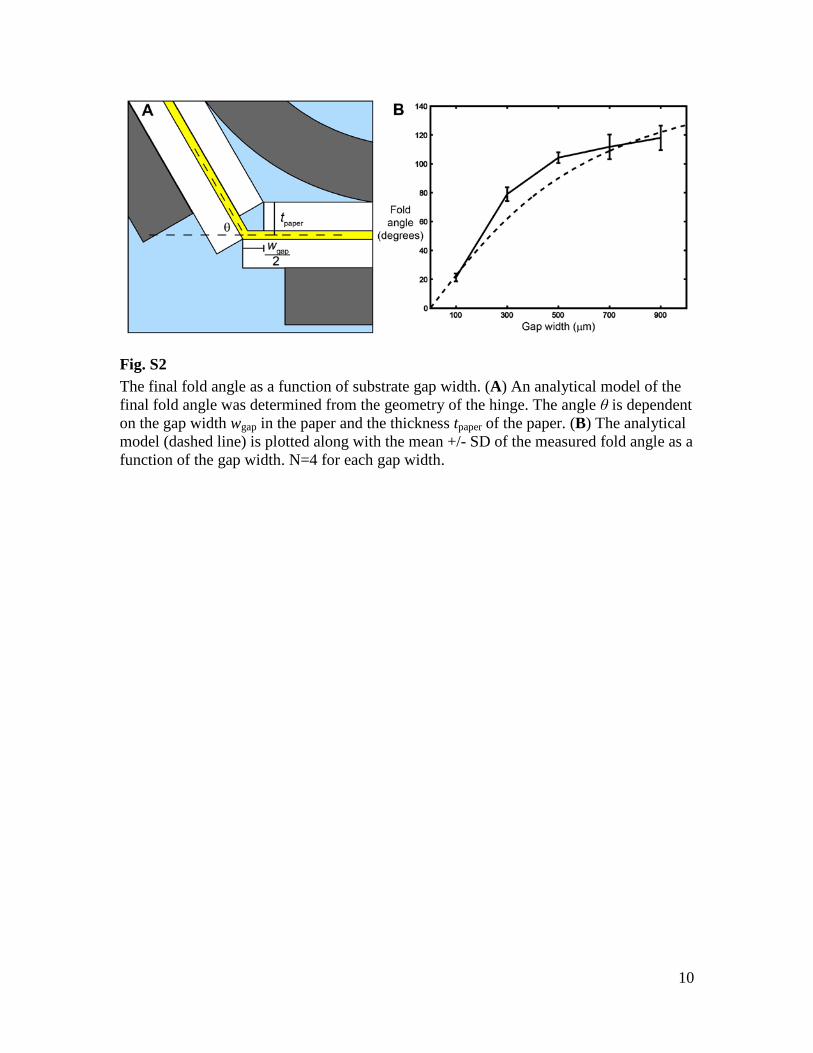
The final angle of the fold can be programmed by varying the width of the paper gap on the concave side. As the hinge folds, the paper on either side of the hinge eventually comes into contact, stopping the fold from progressing. By varying the width of this gap, we can control when this stop occurs, setting the final angle of the fold. To demonstrate this, we created test hinges that were 30 mm long and 30 mm wide to measure the relationship between hinge angle θ, gap width wgap, and paper thickness tpaper. We supplied the resistive circuits with 2.5 A for two to three minutes, until self-folding was complete. The final fold angle is compared to an analytical model based on the geometry of the hinge, θ = 2arctan(wgap/2tpaper) (Fig. S2). The experimental results show that the final fold angle is greater than the model predicts; we believe this is because the model

3
assumes that the paper is incompressible, but in reality the corners deform under load. The maximum fold angle is limited by the shrink ratio of the PSPS layer, in this case limiting the angle to approximately 120°.
Self-folding machines also require dynamic hinges for movement, and these too are programmed into the composite via layer-specific features. A gap is cut into each paper and PSPS layer at the hinge, so that the hinge stiffness is determined by the bending stiffness of the polyimide (Fig. 1, D and E). The range of bending is determined by the gap width, and dynamic hinges that bend in only one direction can be created by cutting a slit of negligible width on the opposite side. Algorithmic results
It was first established in 1999 that every polyhedral complex (that is, a union of polygons in 3-D) can be folded from a sufficiently large square of paper (10). Unfortunately, these original algorithms were impractical, wasting most of the material and making folds through many layers of paper. Recently, the Origamizer approach has proven to be a practical approach to folding arbitrary polyhedra (12). For example, T. Tachi, the creator of Origamizer, can fold a square of paper into the classic Stanford bunny 3-D model (at a resolution of 374 triangles) by hand (Fig. S3). This software is freely available (34). The algorithm can be simplified for self-folding machines because we have the luxury of arbitrarily cutting the sheet material. By cutting out the complex “vertex tucking molecules” used in Origamizer, the resulting foldings involve “edge tucks” (180° folds bringing two polyhedron edges together, folded to the dihedral angle in the polyhedron) connected in a group of cycles mimicking the combinatorial structure of the desired polyhedral surface (cut to reduce an arbitrary topology to a simple disk). We have demonstrated a self-folding composite that can make these types of folds using cyclic fold patterns, and we therefore expect it to practically reproduce many Origamizer-generated designs.
The so-called Kempe Universality Theorem states that a 2D bar-and-joint linkage can “sign your name”, that is, trace any desired polynomial curve. Kempe gave a beautiful construction for this problem in 1876, but did not actually prove the theorem. The first published proof established a more general result, allowing the trace of any algebraic set defined by a system of polynomials (31). This proof was subsequently simplified and generalized to an asymptotically optimal algorithm for linkage construction in arbitrary dimensions (32). Although theoretically optimal, these algorithms still require many joints. Recently, a practical implementation has been developed that approximates a desired motion (as required by a robot, for example) by a designed linkage with very few joints (33). These constructions employ universal hinges connected by rigid bars, but it is easy to convert such constructions into panel-and-hinge structures; for example, we can extrude any of the 2D constructions orthogonally into 3-D. We have demonstrated a self-folding composite that can make panel-and-hinge structures, and therefore we expect it to be capable of practically reproducing many linkage mechanism designs. Robot design
Because cyclic folds can be extrapolated to produce arbitrary geometries, we incorporated them into the robot’s fold pattern. The robot's body is formed with a six-hinge cyclic fold, which stiffens the body and raises it from the ground, while angling the legs downward (Fig. 2H). Each leg consists of a four-edge, single-vertex fold (Fig. 2G),
4
which is a type of cyclic fold with a single degree of freedom. It provides rigidity to the legs and also aids in the formation of the linkages. Because this fold has a single degree of freedom, the redundant actuation of the folds increases the effective force of the folding. This is necessary to pull the linkage system into position.
The dynamic capabilities of this self-assembly method are demonstrated by the walking motion of the robot, driven by a motor on each side. Each motor drives a front and back leg (Fig. 3B) through an eight-bar linkage. The purpose of the linkage is to transform the cyclic motion of the motor into an approximately cyclic trajectory in each foot to mimic a walking motion. Linkage lengths are given in Table S1.
In addition to the desired foot trajectory, there are other considerations when designing linkages for folded machines. The linkage design is constrained so that the lengths sum to zero. This ensures that the linkages can lay in a flat conformation prior to folding, and do not have to change length during assembly (Fig. 3A). While it is possible with this method to change the effective length of linkages during assembly, we chose not to in order to simplify the design. The dynamic hinges are castellated – meaning that the hinge line is staggered in a square wave pattern (Fig. 1H). This is done to increase the off-axis stiffness without decreasing their range. However, there is still a minimum hinge width required to bear a particular load. For the loads experienced by the linkages of the self-folding robot, this width is approximately seven millimeters. Finally, the linkage design is constrained by the torque exerted by the folding hinges during assembly. Some linkage designs would require more torque to self-assemble than the actuated folds could provide. The final linkage design for the robot was selected with these constraints in mind and using a combination of kinematic simulations and prototype testing.
These linkages also demonstrate that this assembly technique is capable of precision alignment by requiring that the crank arm pin couple into a specific slot on the linkage mechanism. This is accomplished by first folding tabs with an alignment notch during the folding of the legs (Fig. S4B). After the legs have folded and the linkages are in position, the motors rotate 180°, pushing the crank arm pin into the notch (Fig. S4C). A locking tab on the far side of the linkage then folds around the pin, coupling it with the linkage mechanism (Fig. S4D).
Two additional, static legs are included in the middle of the body to provide stability (Fig. 3B). The gait is designed so that the front and back legs of one side plant and move simultaneously. Each side alternates planting so that when the legs on the left side are planted, the legs on the right side are in the air. The middle leg is positioned to support the robot when the dynamic legs are up by providing three points of contact – the middle leg on one side and the dynamic legs on the other.
Autonomous assembly is accomplished with embedded circuitry and an onboard power supply (Fig. S5). Both assembly and locomotion are controlled by a single microcontroller with six outputs: three binary outputs to control folding, and one binary and two pulse-width-modulation outputs to control the two motors. Folding is triggered by current that is gated by four MOSFETs. Locomotion is actuated through two motors, which are controlled by the microcontroller via motor driver integrated circuits. The self-assembly process comprises five steps (Fig. 2, Movie S1):
1. From 0-75 s, the outer legs and dynamic linkages fold into position, and alignment tabs fold into place.
2. At 85 s, the motors turn 180° to align the crank arm pins with the alignment tabs.

5
3. From 85-182 s, the body folds and locking tabs fold over the crank arm pins. 4. At 212 s, the motors turn 180°, causing the robot to stand up. 5. From 212-260 s, the middle legs fold downward. Self-assembly is programmed to occur ten seconds after power is connected to the
circuit, and each step occurs at a preprogrammed time. After each folding step, 10-30 s were allowed to pass before the next step commenced, to allow the hinges to cool and harden. Power is supplied from two batteries with a nominal voltage of 7.4 V. The resistive circuits are voltage limited, so the resistance of each trace is adjusted to result in a current that falls between 2-2.5 A for desired heating. Voltage to the microcontroller and motor drivers is controlled by two voltage regulators.
One strength of this technique is the speed of the development cycle. This robot design evolved through prototyping over 40 iterations (Fig. S6). This would have been prohibitively expensive using traditional machining techniques. Many limitations, such as minimum hinge size, trace width, and linkage lengths, were determined experimentally. The designs were produced using the design feature of the Solidworks computer-aided design software. Because these drawings are 2-D they are easy to modify and compatible with a variety of computer aided design programs, many of which are free.
One limitation of this technique is the substantial design time required. Currently, determining the appropriate fold patterns and hinge geometries takes several hours and some trial and error. However, the origami nature of this technique makes it tractable to consider design automation algorithms. Several programs have already been developed to aid in the design of folded structures and machines (12, 13). Scalability
The materials used here were selected because they are inexpensive and commercially available. They are capable of hinges as short as 5 mm, and are well-suited for building structures and machines from 100 to 300 mm in length (24, 29).
The primary challenge to folding larger structures is the weight of the folding faces, which must be matched or exceeded by the torque exerted by the hinges. As the structure grows uniformly, the hinge torque grows as O(L3). However, the moment due to gravity is O(L4), so as L increases, the moment due to gravity exceeds the hinge torque. The relationship between composite design and hinge torque is explored in Felton et al. (24), and we have created an analytical model to relate the maximum feature size with the uniaxial SMP recovery stress σr and thickness tsmp. In this model the SMP is constrained along both axes that are parallel with the composite at a strain of εr. and the stress of the SMP in the hinge σh is equal in both of these axes, and zero in the perpendicular axis (plane stress). Therefore, we can solve for σh as a function of σr in eq. 1. We solve for the torque τ exerted by the SMP in eq. 2, and τ exerted by gravity on the hinge face in eq. 3. We use this along with published examples of SMPs to determine the maximum length L of a square folding face that an SMC incorporating that material could lift (Table S2). L is calculated by solving for the face length at which the torque exerted by gravity is equal to the torque exerted by the hinge, as shown in eq. 4. By choosing the appropriate SMP, we calculate a maximum possible face length of 1.59 m. Other variables and values used in this model are given in Table S3. We have also used this model to calculate the combined torque of the hinges on the crawling robot. With a total hinge width of 688 mm, the hinges exerted a combined 150 mNm during self-assembly.
6
( )1rr h hE E
σε σ νσ= = − (1)
( ) ( )2 2
22
paper smp
paper
t tpaper smp paper
h rt
t t twtdt wτ σ σ
+ + −= =∫ (2)
( )2 22 2smp smp paper paperL LFd mg wL t tτ ρ ρ = = = +
(3)
( ) ( )2 2 2smp smp paper paper r smp smp paperL t t t t tρ ρ σ+ = − (4) At smaller sizes (1-20 mm), the resolution is limited by fabrication methods and the
composite thickness. The laser machining system that was used to build the self-folding robot has a spatial resolution of approximately 1 mm, based on the laser diameter and proximal warping of the material due to heat, and the masking process cannot reliably produce traces thinner than 0.3 mm. However, fabrication methods for producing complex functional laminates, known as PC-MEMS, have been demonstrated. Centimeter-long robots have already been built using these planar fabrication techniques (17) with feature sizes smaller than one millimeter. Adapting these machining methods and materials to self-folding laminates is straightforward. Therefore, the methods presented in this work are suitable for creating machines over three orders of magnitude in characteristic dimensions – approximately one millimeter to one meter. Comparison to 3-D printing
Because of its applications as a form of printable manufacturing, self-assembly by folding draws comparisons to 3-D printing. In particular, we are interested in the relative cost and speed of manufacturing equivalent devices. For these comparisons, we consider a 3-D printed structure with a similar shape and size to the self-folding robot. However, it is important to note that self-assembly by folding integrates electronics naturally into the fabrication process, and this is not included in the following estimates for 3-D printing.
The materials used in our robot cost approximately $19, before the addition of motors, batteries and other components (Table S4). A 3-D printed structure of similar size would require 780 g of structural and support material costing approximately the same, depending on the material and printer.
The primary strength of self-assembly by folding as compared to 3-D printing is speed of assembly. As can be seen in Video S2, the manufacturing process for the self-folding machine takes less than two hours, and the folding process takes four minutes. 3-D printing a structure of similar size and shape took 5 hours and 17 minutes with an Objet500 Connex 3-D printer in ‘high speed’ mode, the fastest machine available to us. Many 3-D printers would take 10 or more hours. This speed would also be significantly slower if multiple materials were required, for instance if electrical traces were included in the printing process. Energy Consumption
The energy expended during assembly by the machine demonstrated in this paper is the predominant factor in determining the size and type of batteries that are installed and carried. However, it is important to note that the energy necessary for folding is already stored in the SMP layer, and the energy expended by the batteries is only necessary to stimulate the phase transition. Because of this, there are two approaches to reducing the energy expenditure. The first is to alter the transition temperature of the SMP. Xie et al.
7
have already demonstrated a practical method for setting the transition temperature of an epoxy SMP anywhere from room temperature to 89°C (35). While reducing the transition temperature of a self-folding machine would make the device more susceptible to premature assembly due to heat, in many circumstances this risk would be worth the substantial reduction in activation energy. Based on previously published models (24), we estimate that if we reduced the transition temperature of the SMP used in this machine to 60° C, we could reduce the activation current by 70% and the energy expended during self-assembly by 50%.
Alternatively, we could deliver a larger current at a higher voltage. While this requires greater power, the reduction in folding time would reduce the total expended energy. Increasing the voltage and current by 40% would double the power, but would reduce the fold time by 93% (expected fold time of 3 s instead of 45 s), resulting in total energy expenditure of 86% less than our current implementation (24). The complication with this technique is that if the current is supplied for too long a period, the SMP would overheat and melt. Because of this, we recommend that this method be used with sensors embedded in the hinges to provide angle and temperature feedback during the folding process. In this way, the controller would know when to switch off current to a folding hinge, and would have the added benefit of producing more precise folds.
The size of the machine will also affect the power expended during self-assembly. For a given self-folding device, the energy released is relatively uniform along the length of the hinges. For a machine of a given complexity, the total length of the hinges will scale directly with the length of machine, and so the energy consumed during assembly will also scale directly with machine length. Based on previous experiments, SMP thickness and hinge torque have little effect on power requirements (24), so the weight of the machine would have a minimal impact on energy consumption during assembly. However, more complex machines will require more folds, and therefore more energy.
It is also possible to use SMPs that are triggered by non-thermal stimuli that require less energy. There are several published examples of SMPs that exhibit a shape change in response to water (36), light (37), magnetic fields (38), or mechanical stress (39). Adaptability
The manufacturing process could be expanded with the development of printable batteries (40) and actuators, which would further improve manufacturing speed and customization. If the inclusion of a circuit layer is prohibitively expensive, but self-assembly is occurring in a dedicated facility, sequential activation could be accomplished via an external heater such as a laser (41). For simpler geometries, a modified technique could be accomplished by heating the composite in an oven (28). For space applications, an embedded heating source may not be necessary. Black lines could be used to absorb thermal radiation from the sun along the hinges (8, 28). For environments with large thermal variations, the transition temperature can be raised as high as 150°C (42), and SMPs can be used that are triggered by non-thermal stimuli such as those listed above (36, 37, 39).
Another option for self-folding composites is to integrate shape memory alloys (SMAs) as the contractile layer. SMAs have already been used in self-folding structures (7). Generally SMAs have an actuated strain of less than 10%, making them ill-suited to the bimorph folding actuators used in this paper. However, they can exert stresses of up to 600 MPa (43), 20 times higher than the largest stress an SMP from Table S2 could

8
exert. To achieve large fold angles, the hinge geometry could be modified so that small deflections in the contractile layer result in larger fold angles in the composite. Repeatability
Three self-folding robots were constructed, and one achieved functionality. In the other two, a single hinge failed to fold into the necessary position. In one robot, the locking tab failed to align with the crank arm pin, preventing coupling. In the other, the locking tab failed to fold at all, and the PSPS in that area delaminated from the paper.
During these trials, the failed hinge was pushed into place manually so that the assembly process could finish to observe if there were other points of failure. Considering that each robot consists of 28 hinges, the folding success rate is 97.6%.

9
Fig. S1. The fabrication process of the self-folding robot. This process harnesses planar techniques to rapidly produce self-folding machines. (A) A mask is applied to a sheet of copper-polyimide using a solid ink printer. (B) The copper-polyimide is etched with ferric chloride. (C) The copper-polyimide layer, as well as two sheets of PSPS and two sheets of paper, are laser-machined with layer-specific features. (D) These layers are bonded together by hand, using silicone tape. (E) The final composite is laser-machined again. (F) Electrical components, motors, and batteries are added either manually, or with a pick-and-place machine.
10
Fig. S2 The final fold angle as a function of substrate gap width. (A) An analytical model of the final fold angle was determined from the geometry of the hinge. The angle θ is dependent on the gap width wgap in the paper and the thickness tpaper of the paper. (B) The analytical model (dashed line) is plotted along with the mean +/- SD of the measured fold angle as a function of the gap width. N=4 for each gap width.

11
Fig. S3 3-D model and fold pattern of the Stanford bunny 3-D test model. Origamizer is a free computer program capable of transforming almost any polyhedron into a planar crease
pattern. It relies primarily on cyclic folds (10, 12). (A) The original Stanford Bunny Model. (B) The model approximated as a polyhedron with 374 faces. (C) The planar fold
pattern generated from the polyhedral approximation using the Origamizer algorithm.

12
Fig. S4 The motor and alignment mechanism of the robot. (A) The linkages are fabricated in plane with the composite, and the crank arms are oriented upward. (B) The legs and linkages fold into position, and the alignment tab folds into place. (C) The motor rotates 180°, pushing the crank arm pin into the alignment notch. (D) The locking tab folds over the pin, coupling the pin to the linkage. In (C) and (D) the obscuring linkage is displayed in outline only for clarity.

13
Fig. S5 The electrical circuit of the self-folding robot. The crawling machine uses a flexible printed circuit board (PCB) integrated into the laminate to control both assembly and locomotion. (A) The trace pattern of the machine's PCB. Red, blue, and green traces indicate the current path during activation of the first, second, and third folding steps, respectively. (B) The machine's circuit diagram, including one microcontroller, two motor drivers, two voltage regulators, two motors, two batteries, and four MOSFETs. (C) The flexible PCB layer of the machine, with all electrical components installed.

14
Fig. S6 Prototypes of the crawling robot. The crawling machine was designed through prototyping that required over 40 iterations. Six of these are shown here, including the final design in the bottom right.

15
Table S1. The lengths of the linkages used to drive the machine’s legs.
Linkage Length (mm) L1 85 L2 20 L3 24.5 L4 10 L5 30 L6 15 L7 68.5 L8 70.5 F1 50 F2 45

16
Table S2. Shape memory materials that could be used in the self-folding composite.
Material Recovery stress (MPa)
Thickness (µm)
Maximum face length (m)
Polystyrene 0.7 250 0.19 Polystyrene 0.7 500 0.24 DiAPLEX (44) 2 500 0.41 Morthane with nanotubes (45) 7 500 0.77 Cross-linked HYPU (46) 16 500 1.16 Cross-linked PVAc-PLA (42) 30 500 1.59

17
Table S3. The variables and values used in the analytical model predicting hinge torque.
Variable Symbol Value Unit Gravity acceleration g 9.8 m/s2 SMP thickness tsmp 250 µm SMP density ρsmp 1155 kg/m3 SMP Poisson’s ratio ν 0.5 - Paper thickness tpaper 500 µm Paper density ρpaper 660 kg/m3 Folding face length L - m Folding face mass m - kg SMP Young’s modulus E - Pa SMP recovery stress σr - Pa SMP recovery strain εr - - SMP hinge stress σh - Pa Torque τ - N-m Hinge length w - m Force of gravity F - N Lever arm d - m

18
Table S4. The material and component costs of the self-folding robot. All of these prices are for purchasing quantities of 10 or less, or less than 4 square meters of sheet material.
Structural Materials Amount Cost (USD) Polystyrene 0.068 m2 0.49 Paper 0.068 m2 1.01 Copper-Polyimide 0.034 m2 6.73 Tape 0.136 m2 10.84 Subtotal - 19.07 Operational Components - - Motors 2 40 Electronic Components 21 19.04 Batteries 2 21.98 Total - 100.09

19
Movie S1 The crawling machine self-assembled over 270 s. The self-assembling process occurs in five steps: outer leg folding, motor alignment, body folding, standing up, and inner leg folding. After self-assembly, it walks without any further intervention.
Movie S2 The assembly process uses planar fabrication methods to make assembly fast and easy. Fabrication requires a solid ink printer, a ferric chloride etch tank, a laser machining system, and a board and pins for aligning the layers.

References
1. P.-A. Monnard, D. W. Deamer, Membrane self-assembly processes: Steps toward the first
cellular life. Anat. Rec. 268, 196–207 (2002). Medline doi:10.1002/ar.10154
2. N. R. Franks, A. Wilby, B. W. Silverman, C. Tofts, Self-organizing nest construction in ants:
Sophisticated building by blind bulldozing. Anim. Behav. 44, 357–375 (1992).
doi:10.1016/0003-3472(92)90041-7
3. R. Pfeifer, M. Lungarella, F. Iida, Self-organization, embodiment, and biologically inspired
robotics. Science 318, 1088–1093 (2007). Medline doi:10.1126/science.1145803
4. G. M. Whitesides, B. Grzybowski, Self-assembly at all scales. Science 295, 2418–2421
(2002). Medline doi:10.1126/science.1070821
5. M. Schenk, S. D. Guest, Origami folding: A structural engineering approach. Origami 5, 291–
304 (2011). doi:10.1201/b10971-27
6. J. Guan, H. He, D. J. Hansford, L. J. Lee, Self-folding of three-dimensional hydrogel
microstructures. J. Phys. Chem. B 109, 23134–23137 (2005). Medline
doi:10.1021/jp054341g
7. E. Hawkes, B. An, N. M. Benbernou, H. Tanaka, S. Kim, E. D. Demaine, D. Rus, R. J. Wood,
Programmable matter by folding. Proc. Natl. Acad. Sci. U.S.A. 107, 12441–12445
(2010). Medline doi:10.1073/pnas.0914069107
8. Y. Liu, J. K. Boyles, J. Genzer, M. D. Dickey, Self-folding of polymer sheets using local light
absorption. Soft Matter 8, 1764–1769 (2012). doi:10.1039/c1sm06564e
9. Y. W. Yi, C. Liu, Magnetic actuation of hinged microstructures. J. Microelectromech. Syst. 8,
10–17 (1999). doi:10.1109/84.749397
10. E. D. Demaine, M. L. Demaine, J. S. B. Mitchell, Folding flat silhouettes and wrapping
polyhedral packages: New results in computational origami. Comput. Geom. 16, 3–21
(2000). doi:10.1016/S0925-7721(99)00056-5
11. G. Song, N. M. Amato, A motion-planning approach to folding: From paper craft to protein
folding. IEEE Trans. Robot. Autom. 20, 60–71 (2004). doi:10.1109/TRA.2003.820926

12. T. Tachi, Origamizing polyhedral surfaces. IEEE Trans. Vis. Comput. Graph. 16, 298–311
(2010). Medline doi:10.1109/TVCG.2009.67
13. B. An et al., An end-to-end approach to making self-folded 3D surface shapes by uniform
heating. Paper presented at the IEEE International Conference on Robotics and
Automation, Hong Kong, 31 May to 7 June 2014.
14. H. Okuzaki, T. Saido, H. Suzuki, Y. Hara, H. Yan, A biomorphic origami actuator fabricated
by folding a conducting paper. J. Phys. Conf. Ser. 127, 012001 (2008). doi:10.1088/1742-
6596/127/1/012001
15. P. Birkmeyer, K. Peterson, R. S. Fearing, DASH: A dynamic 16g hexapedal robot. Paper
presented at the IEEE International Conference on Intelligent Robots and Systems, St.
Louis, 11 to 15 October 2009.
16. H. C. Greenberg, M. L. Gong, S. P. Magleby, L. L. Howell, Identifying links between
origami and compliant mechanisms. Mech. Sci. 2, 217–225 (2011). doi:10.5194/ms-2-
217-2011
17. P. S. Sreetharan, J. P. Whitney, M. D. Strauss, R. J. Wood, Monolithic fabrication of
millimeter-scale machines. J. Micromech. Microeng. 22, 055027 (2012).
doi:10.1088/0960-1317/22/5/055027
18. S. M. Felton, M. T. Tolley, C. D. Onal, D. Rus, R. J. Wood, Robot self-assembly by folding:
A printed inchworm robot. Paper presented at the IEEE International Conference on
Robotics and Automation, Karlsruhe, Germany, 6 to 10 May 2013.
19. K. Miura, Method of packaging and deployment of large membranes in space. Inst. Space
Astronaut. Sci. Rep. 618, 1–9 (1985).
20. F. C. Moon, J. F. Abel, “Nonlinear dynamics of deployable and maneuverable space
structures” (Tech. Rep. ADA275022, Cornell University, Ithaca, NY, 1993).
21. A. S. Soo, “Rapidly deployable structures in collective protection systems” (Tech. Rep.
ADA444670, Army Soldier and Biological Chemical Command, Natick, MA, 2006).

22. J. Mejia-Ariza, T. W. Murphey, E. L. Pollard, “Manufacture and experimental analysis of a
concentrated strain based deployable truss structure” (Tech. Rep. ADA453559, Virginia
Polytechnic Institute and State University, Blacksburg, VA, 2006).
23. C. D. Onal, R. J. Wood, D. Rus, Towards printable robotics: Origami-inspired planar
fabrication of three-dimensional mechanisms. Paper presented at the 2011 IEEE
International Conference on Robotics and Automation, Shanghai, 9 to 13 May 2011.
24. S. M. Felton, M. T. Tolley, B. H. Shin, C. D. Onal, E. D. Demaine, D. Rus, R. J. Wood, Self-
folding with shape memory composites. Soft Matter 9, 7688–7694 (2013).
doi:10.1039/c3sm51003d
25. See supplementary materials on Science Online.
26. L. L. Howell, A. Midha, A method for the design of compliant mechanisms with small-
length flexural pivots. J. Mech. Des. 116, 280–290 (1994). doi:10.1115/1.2919359
27. B. P. Trease, Y. M. Moon, S. Kota, Design of large-displacement compliant joints. J. Mech.
Des. 127, 788–798 (2005). doi:10.1115/1.1900149
28. M. T. Tolley et al., Self-folding shape memory laminates for automated fabrication. Paper
presented at the IEEE International Conference on Intelligent Robots and Systems,
Tokyo, 3 to 8 November 2013.
29. B. Shin, S. M. Felton, M. T. Tolley, R. J. Wood, Self-assembling sensors for printable
machines. Paper presented at the IEEE International Conference on Robotics and
Automation, Karlsruhe, Germany, 31 May to 7 June 2014.
30. T. Tachi, Simulation of rigid origami. Origami 4, 175–187 (2009). doi:10.1201/b10653-20
31. M. Kapovich, J. J. Millson, Universality theorems for configuration spaces of planar
linkages. Topology 41, 1051–1107 (2002). doi:10.1016/S0040-9383(01)00034-9
32. T. G. Abbott, thesis, Massachusetts Institute of Technology (2008).
33. S. Coros et al., Computational design of mechanical characters. ACM Trans. Graphics 32, 83
(2013).
34. T. Tachi, Origamizer (www.tsg.ne.jp/TT/software).

35. T. Xie, I. A. Rousseau, Facile tailoring of thermal transition temperatures of epoxy shape
memory polymers. Polymer 50, 1852–1856 (2009). doi:10.1016/j.polymer.2009.02.035
36. Y. Zhu, J. Hu, H. Luo, R. J. Young, L. Deng, S. Zhang, Y. Fan, G. Ye, Rapidly switchable
water-sensitive shape-memory cellulose/elastomer nano-composites. Soft Matter 8,
2509–2517 (2012). doi:10.1039/c2sm07035a
37. A. Lendlein, H. Jiang, O. Jünger, R. Langer, Light-induced shape-memory polymers. Nature
434, 879–882 (2005). Medline doi:10.1038/nature03496
38. J. M. Cuevas, J. Alonso, L. German, M. Iturrondobeitia, J. M. Laza, J. L. Vilas, L. M. León,
Magneto-active shape memory composites by incorporating ferromagnetic microparticles
in a thermo-responsive polyalkenamer. Smart Mater. Struct. 18, 075003 (2009).
doi:10.1088/0964-1726/18/7/075003
39. B. Heuwers, D. Quitmann, F. Katzenberg, J. C. Tiller, Stress-induced melting of crystals in
natural rubber: A new way to tailor the transition temperature of shape memory
polymers. Macromol. Rapid Commun. 33, 1517–1522 (2012). Medline
doi:10.1002/marc.201200313
40. K. Sun, T. S. Wei, B. Y. Ahn, J. Y. Seo, S. J. Dillon, J. A. Lewis, 3D printing of
interdigitated Li-ion microbattery architectures. Adv. Mater. 25, 4539–4543 (2013).
Medline doi:10.1002/adma.201301036
41. K. E. Laflin, C. J. Morris, T. Muqeem, D. H. Gracias, Laser triggered sequential folding of
microstructures. Appl. Phys. Lett. 101, 131901 (2012). doi:10.1063/1.4754607
42. C. Liu, H. Qin, P. T. Mather, Review of progress in shape-memory polymers. J. Mater.
Chem. 17, 1543–1558 (2007). doi:10.1039/b615954k
43. P. Krulevitch, A. P. Lee, P. B. Ramsey, J. C. Trevino, J. Hamilton, M. A. Northrup, Thin
film shape memory alloy microactuators. J. Micromech. Microeng. 5, 270–282 (1996).
doi:10.1109/84.546407
44. D. Ratna, J. Karger-Kocsis, Recent advances in shape memory polymers and composites: A
review. J. Mater. Sci. 43, 254–269 (2008). doi:10.1007/s10853-007-2176-7

45. H. Koerner, G. Price, N. A. Pearce, M. Alexander, R. A. Vaia, Remotely actuated polymer
nanocomposites—stress-recovery of carbon-nanotube-filled thermoplastic elastomers.
Nat. Mater. 3, 115–120 (2004). Medline doi:10.1038/nmat1059
46. J. Xu, W. Shi, W. Pang, Synthesis and shape memory effects of Si-O-Si cross-linked hybrid
polyurethanes. Polymer 47, 457–465 (2006). doi:10.1016/j.polymer.2005.11.035


![October13,2020 arXiv:2010.05592v1 [math.AP] 12 Oct 2020If 0 ≤ Ω Ω∗, then for any a≥ 0,](https://img.pdfslide.us/doc/110x75/60c91489e4b5582ea2565373/october132020-arxiv201005592v1-mathap-12-oct-2020-if-0-a-a-then.jpg)

![Vision-Based Relative Navigation and Control for Autonomous … · American Institute of Aeronautics and Astronautics 3 with [ ] T m mx my mz ω = ω ω ω denoting the inspector](https://img.pdfslide.us/doc/110x75/5e7e173347cbfc4ede6f064a/vision-based-relative-navigation-and-control-for-autonomous-american-institute-of.jpg)