Embed Size (px)
Citation preview
326
Superconductively levitated transport system – the SupraTrans project
O. de Haas1*, L. Schultz1, P. Verges1, C. Beyer1, S. Röhlig2, H. Olsen2, L. Kühn3, D. Berger4,
U. Noteboom5, 1IFW Dresden, Leibniz-Institut für Festkörper- und Werkstoffforschung, Helmholtzstr. 20,
01069 Dresden, Germany, * +49 351 4659 209 / +49 351 4659 541, [email protected]
2ELBAS GmbH, PF 10 09 44, 01079 Dresden, Germany 3HTW Dresden, PF 12 07 01, 01008 Dresden, Germany
4 Baumüller Kamenz GmbH, Nordstraße 57, 01917 Kamenz, Germany 5 CIDEON engineering GmbH, Tzschirnerstr. 5a, 02625 Bautzen, Germany
Acknowledgements
The support of the project in the context of the technology promotion with means of the European fund for regional development (EFRE) 2000 - 2006 and with means of the Free State of Saxony is greatfully acknowledged. Thanks are due to U. Funk (DVB AG), G. Hofmann (HTW Dresden) and G. Fuchs (IFW Dresden) for stimulating discussions, to W. Pfeiffer (IFW Dresden) and H.-J. Brauns for the preliminary project planning and to G. Krabbes for preparation of superconducting materials.
Keywords
Superconductivity, Magnetic Levitation, Transporting System, SupraTrans
Abstract
SupraTrans® is an innovative transportation concept based on the rational of superconductively magnetic levitation. The aim of our project is to create a full working prototype, which proofs its ability for passenger transport by explicit consideration of the compatibility between systems for propulsion, safety, positioning, power supply, transport logistics and the levitation system itself. The SupraTrans technology uses the feature of flux pinning in High Temperature Superconductors (HTS) to stabilize the lateral position of the vehicle on the magnetic track. This self-stabilizing system is the main advantage of the superconductive levitation in comparison to all other levitation systems, which need electronic controls and power to keep a constant distance between the train and the track. With this contribution we will give an introduction to the project and report the current status of the demonstrator development.
1 Introduction Magnetic levitation on the basis of electrostatic or magnetostatic interactions between macroscopic bodies is impossible, so the sobering conclusion to draw from Samuel Earnshaws theorem published in 1842 [1]. Most of today´s solutions for magnetic levitation are therefore based on dynamically controlled electromagnets, facing all the problems of sophisticated control systems and considerable power consumption. The more seducing is it to find a system with the simplicity of a fixed arrangement of magnets and iron yokes, which does not violate Earnshaws theorem. The system, which fulfills all these requirements, consists of superconducting materials levitating in the static magnetic field of permanent magnets. Several groups are working on projects to use this simple
327
technique to design new machines with frictionless rotating bearings [2-5]. Also linear bearings can be made by superconducting levitation. The idea to set up a superconductive maglev transporting system is then just a small step away. The first man loading maglev system of this kind was presented in Chengdu, China in 2002 [6]. The SupraTrans project has started to develop a demonstrator containing all components needed for a transporting system and also taking into account the requirements of a future operator. SupraTrans is therefore a joint venture of research institutes (IFW Dresden), universities (Dresden University of Technology, University of Applied Sciences Dresden), industrial companies (ELBAS GmbH–railway consulting and engineering, Baumüller Kamenz–linear drives, CIDEON engineering Bautzen–railway conveyer design) and the Dresden Transportation Company (DVB AG) as a potential user. Together we will design a fully working demonstrator and a test line, which allows us to study all the mentioned issues.
2 Superconductivity
2.1 History Superconductivity has been discovered by the Dutch scientist Heike Kamerlingh Onnes in 1911 when he investigated the properties of pure elements at very low temperatures close to absolute zero. At 4 K Onnes observed a sudden decrease of the electrical resistance of mercury, which turned out to be a total loss of resistance in further investigations. This effect has been called Superconductivity. Since than, scientists are searching for materials showing this promising effect at higher temperatures to enable its application in cables and electrical machines with vanishing electrical losses. The research for materials with higher critical temperatures made an unexpected large step forward in 1986, when the Swiss K. Alexander Müller and the German J. Georg Bednorz observed superconducting behavior at ceramics on the basis of Cu-O, the so called Cuprates at much higher temperatures. This conceptional break even led to the new class of High-Temperature-Superconductors (HTS), characterized by a critical temperature higher than 196 K, the boiling temperature of liquid nitrogen. Hence superconductivity and its advantages for electrical engineering was accessible with much lower effort for cooling, compared to the sophisticated technology needed for He-cooling Today, the fight for higher and higher critical temperatures has been replaced by a substantial research and developement of materials with optimized properties and the set up of considerable manufacturing methods for a broad range of applications.
2.2 Basics It is obvious that superconductors are almost perfect conductors. Another remarkable feature of them is there ideal diamagnetic behavior. External magnetic fields are expelled from the superconducting body by electrical surface currents. The superconductive state will be destroyed if the magnetic field and hence the necessary shielding currents exceed the critical value. The new HTSC-materials, which belong to the so-called type-II-superconductors, make an exception from this rule. Magnetic fields can penetrate the superconducting matrix by the formation of quantum mechanical flux-lines. Their displacement is strongly suppressed by flux line pinning at nanocrystalline pinning centers. Therefore, the magnetization of a superconductor can not follow a variing magnetic field freely. It remains in the magnetic state, which was present while the superconductor was cooled into the superconducting state instead. This can be used for magnetic bearings. The superconductor is cooled within the field of a permanent magnet guideway or thrust bearing. Mechanical displacements of the superconducting part lead to restoring forces, which corresponds to the pinning forces of the flux lines, so the superconductor remains in a stable position.
328
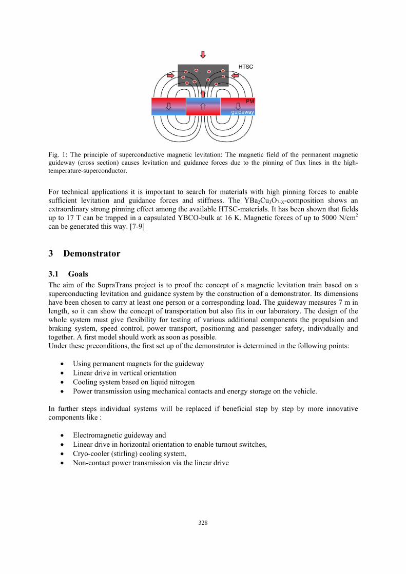
Fig. 1: The principle of superconductive magnetic levitation: The magnetic field of the permanent magnetic guideway (cross section) causes levitation and guidance forces due to the pinning of flux lines in the high-temperature-superconductor.
For technical applications it is important to search for materials with high pinning forces to enable sufficient levitation and guidance forces and stiffness. The YBa2Cu3O7-X-composition shows an extraordinary strong pinning effect among the available HTSC-materials. It has been shown that fields up to 17 T can be trapped in a capsulated YBCO-bulk at 16 K. Magnetic forces of up to 5000 N/cm2 can be generated this way. [7-9]
3 Demonstrator
3.1 Goals The aim of the SupraTrans project is to proof the concept of a magnetic levitation train based on a superconducting levitation and guidance system by the construction of a demonstrator. Its dimensions have been chosen to carry at least one person or a corresponding load. The guideway measures 7 m in length, so it can show the concept of transportation but also fits in our laboratory. The design of the whole system must give flexibility for testing of various additional components the propulsion and braking system, speed control, power transport, positioning and passenger safety, individually and together. A first model should work as soon as possible. Under these preconditions, the first set up of the demonstrator is determined in the following points:
• Using permanent magnets for the guideway • Linear drive in vertical orientation • Cooling system based on liquid nitrogen • Power transmission using mechanical contacts and energy storage on the vehicle.
In further steps individual systems will be replaced if beneficial step by step by more innovative components like :
• Electromagnetic guideway and • Linear drive in horizontal orientation to enable turnout switches, • Cryo-cooler (stirling) cooling system, • Non-contact power transmission via the linear drive
329
3.2 Components
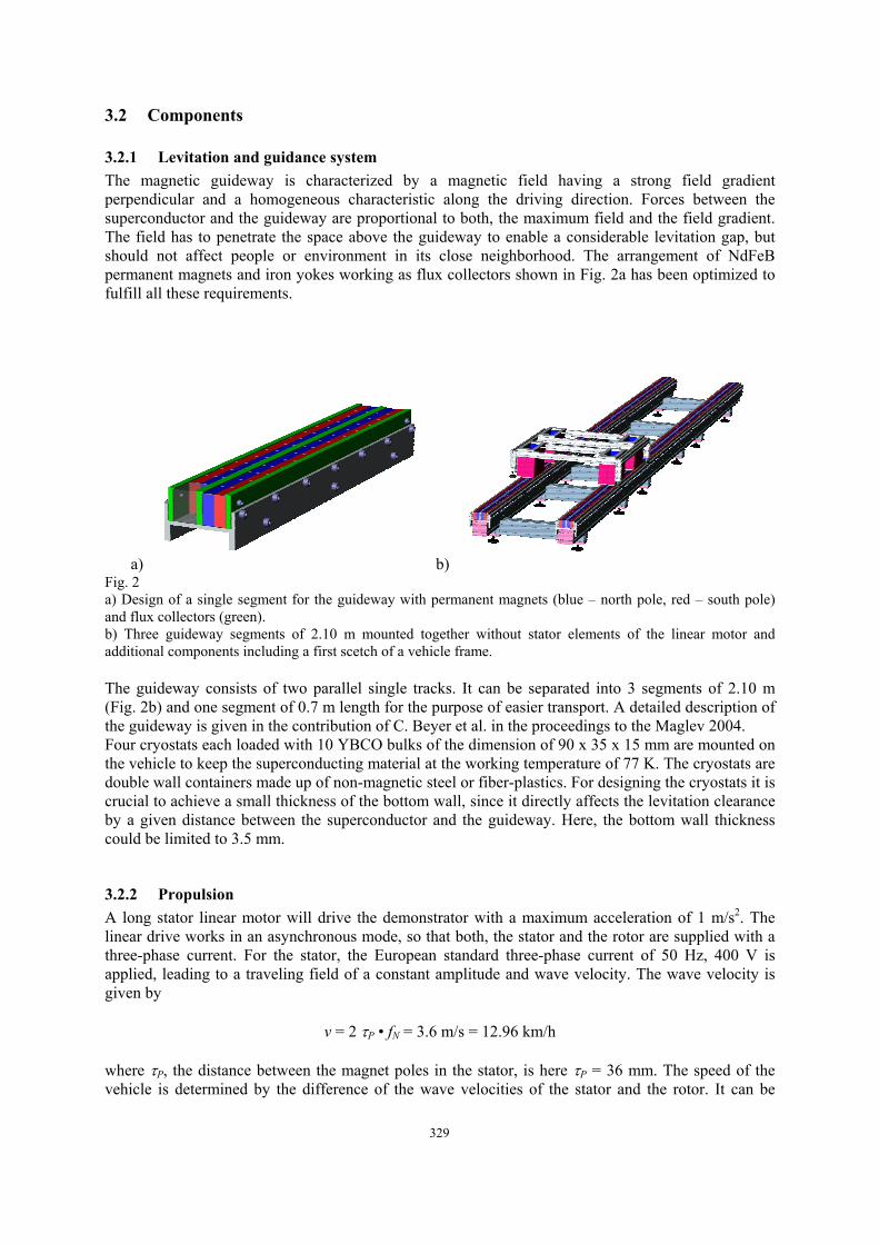
3.2.1 Levitation and guidance system The magnetic guideway is characterized by a magnetic field having a strong field gradient perpendicular and a homogeneous characteristic along the driving direction. Forces between the superconductor and the guideway are proportional to both, the maximum field and the field gradient. The field has to penetrate the space above the guideway to enable a considerable levitation gap, but should not affect people or environment in its close neighborhood. The arrangement of NdFeB permanent magnets and iron yokes working as flux collectors shown in Fig. 2a has been optimized to fulfill all these requirements.
a) b) Fig. 2 a) Design of a single segment for the guideway with permanent magnets (blue – north pole, red – south pole) and flux collectors (green). b) Three guideway segments of 2.10 m mounted together without stator elements of the linear motor and additional components including a first scetch of a vehicle frame. The guideway consists of two parallel single tracks. It can be separated into 3 segments of 2.10 m (Fig. 2b) and one segment of 0.7 m length for the purpose of easier transport. A detailed description of the guideway is given in the contribution of C. Beyer et al. in the proceedings to the Maglev 2004. Four cryostats each loaded with 10 YBCO bulks of the dimension of 90 x 35 x 15 mm are mounted on the vehicle to keep the superconducting material at the working temperature of 77 K. The cryostats are double wall containers made up of non-magnetic steel or fiber-plastics. For designing the cryostats it is crucial to achieve a small thickness of the bottom wall, since it directly affects the levitation clearance by a given distance between the superconductor and the guideway. Here, the bottom wall thickness could be limited to 3.5 mm.
3.2.2 Propulsion A long stator linear motor will drive the demonstrator with a maximum acceleration of 1 m/s2. The linear drive works in an asynchronous mode, so that both, the stator and the rotor are supplied with a three-phase current. For the stator, the European standard three-phase current of 50 Hz, 400 V is applied, leading to a traveling field of a constant amplitude and wave velocity. The wave velocity is given by
v = 2 τP • fN = 3.6 m/s = 12.96 km/h where τP, the distance between the magnet poles in the stator, is here τP = 36 mm. The speed of the vehicle is determined by the difference of the wave velocities of the stator and the rotor. It can be
330
adjusted by the speed control on the vehicle, which sets the frequency of the three phase current in the rotor coils. Depending on phase direction and frequency, the vehicle can stand, break or accelerate to a velocity even higher than the fixed wave velocity of the stator field. The information about the phase shift of the traveling field, which is necessary for generating the corresponding rotor current is obtained by Hall sensors mounted on the vehicle and placed in the air gap of the stator. The stator consists of two rows of vertical oriented stators elements, facing each other with a gap of 20 mm. The rotor board has a thickness of 10 mm floating within the stator gap, resulting in an air gap of 2 x 5 mm. This geometry is advantageous because of its effective use of magnetic energy to generate an appropriate propulsion force. Because of closed flux paths, the magnetic field between two magnetic poles is much higher compared to an open system of just one stator facing a single rotor element. Further, a changing vertical levitation gap (i. e. because of a changing load) causes the rotor to dive deeper in the stator gap but does not affect the air gap between the stator and rotor. However for bended tracks and the construction of turnout switches, the vertical geometry exhibits the disadvantage of either a limited bending radius or discontinuities in the propulsion system.
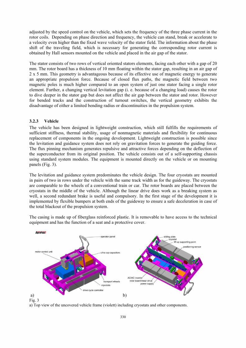
3.2.3 Vehicle The vehicle has been designed in lightweight construction, which still fulfills the requirements of sufficient stiffness, thermal stability, usage of nonmagnetic materials and flexibility for continuous replacement of components in the ongoing development. Lightweight construction is possible since the levitation and guidance system does not rely on gravitation forces to generate the guiding force. The flux pinning mechanism generates repulsive and attractive forces depending on the deflection of the superconductor from its original position. The vehicle consists out of a self-supporting chassis using standard system modules. The equipment is mounted directly on the vehicle or on mounting panels (Fig. 3). The levitation and guidance system predominates the vehicle design. The four cryostats are mounted in pairs of two in rows under the vehicle with the same track width as for the guideway. The cryostats are comparable to the wheels of a conventional train or car. The rotor boards are placed between the cryostats in the middle of the vehicle. Although the linear drive does work as a breaking system as well, a second redundant brake is useful and compulsory. In the first stage of the development it is implemented by flexible bumpers at both ends of the guideway to ensure a safe deceleration in case of the total blackout of the propulsion system. The casing is made up of fiberglass reinforced plastic. It is removable to have access to the technical equipment and has the function of a seat and a protective cover.
a) b) Fig. 3 a) Top view of the uncovered vehicle frame (violett) including cryostats and other components.
331
b) Bottom view of the vehicle including the rotor board of the linear drive (green) which will extend into the stator gap in the guideway.
3.2.4 Operational concept Following the aim of the Supratrans project, to proof the concept of a superconducting magnetic levitation train, the operational concept supports the demonstration and testing of interplay of all technical components. Thereby the vehicle motion is controlled by the vehicle itself or by an operator sitting on the vehicle. This is in contrast to operational concepts of other modern transport systems (i. e. the Transrapid System) but exhibits the advantages of individually driven cars, which interact by formation of a network of intelligent autonomous members. The technical implementation of the demonstrator is based on the demand for a completely wireless vehicle. Two principle operational modes are implemented. In the automatic mode, a predefined operational cycle starts after pressing the start button. Several operational cycles with different parameters for velocity, acceleration and traveling path are available. In the manually controlled mode the vehicle can be driven using a joystick, while the control unit limits the maximum speed, acceleration and deceleration and stops the vehicle at the end of the guideway.
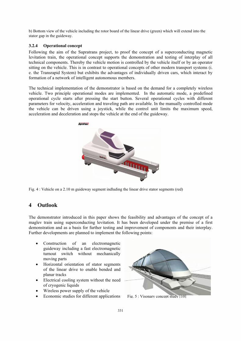
Fig. 4 : Vehicle on a 2.10 m guideway segment indluding the linear drive stator segments (red)
4 Outlook The demonstrator introduced in this paper shows the feasibility and advantages of the concept of a maglev train using superconducting levitation. It has been developed under the premise of a first demonstration and as a basis for further testing and improvement of components and their interplay. Further developments are planned to implement the following points:
• Construction of an electromagnetic guideway including a fast electromagnetic turnout switch without mechanically moving parts
• Horizontal orientation of stator segments of the linear drive to enable bended and planar tracks
• Electrical cooling system without the need of cryogenic liquids
• Wireless power supply of the vehicle • Economic studies for different applications
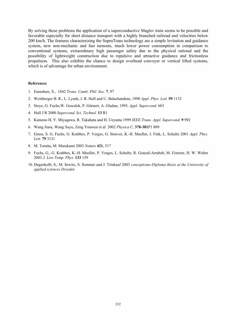
Fig. 5 : Visonary concept study [10]
332
By solving these problems the application of a superconductive Maglev train seems to be possible and favorable especially for short distance transport with a highly branched railroad and velocities below 200 km/h. The features characterizing the SupraTrans technology are a simple levitation and guidance system, new non-mechanic and fast turnouts, much lower power consumption in comparison to conventional systems, extraordinary high passenger safety due to the physical rational and the possibility of lightweight construction due to repulsive and attractive guidance and frictionless propulsion. This also exhibits the chance to design overhead conveyer or vertical lifted systems, which is of advantage for urban environment.
References
1. Earnshaw, S., 1842 Trans. Camb. Phil. Soc. 7, 97
2. Weinberger B. R., L. Lynds, J. R. Hull and U. Balachandran, 1990 Appl. Phys. Lett. 59 1132
3. Stoye, G. Fuchs,W. Gawalek, P. Görnert, A. Gladun, 1995, Appl. Supercond. 683
4. Hull J R 2000 Supercond. Sci. Technol. 13 R1
5. Kameno H, Y. Miyagawa, R. Takahata and H. Ueyama 1999 IEEE Trans. Appl. Supercond. 9 992
6. Wang Jiasu, Wang Suyu, Zeng Youwen et al. 2002 Physica C, 378-381P1 809
7. Gruss, S. G. Fuchs, G. Krabbes, P. Verges, G. Stoever, K.-H. Mueller, J. Fink, L. Schultz 2001 Appl. Phys. Lett. 79 3131
8. M. Tomita, M. Murakami 2003 Nature 421, 517
9. Fuchs, G., G. Krabbes, K.-H. Mueller, P. Verges, L. Schultz, R. Gonzal-Arrabeb, M. Eisterer, H. W. Weber 2003 J. Low Temp. Phys. 133 159
10. Degenkolb, S., M. Sewitz, S. Sommer and J. Trinkauf 2003 conceptrans-Diploma thesis at the University of applied sciences Dresden