Embed Size (px)
Citation preview
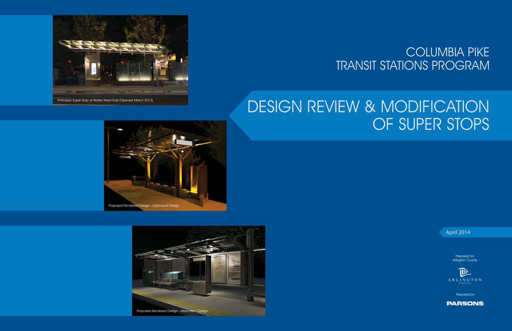
DESIGN REVIEW & MODIFICATIONOF SUPER STOPS
COLUMBIA PIKETRANSIT STATIONS PROGRAM
April 2014
Prepared forArlington County
Prepared by
Prototype Super Stop at Walter Reed East (Opened March 2013)
Proposed Rendered Design - Optimized Design
Proposed Rendered Design - Alternate 1 Design
Columbia Pike Transit Stations Program Design Review and Modification of Super Stops
Parsons ES-1 April 2014
ES EXECUTIVE SUMMARY
ES.1 PURPOSE AND APPROACH
This report documents the design review of and proposed modifications to Arlington County’s Super Stop Program that was undertaken in 2013 after the construction of the first Prototype Super Stop (located at Walter Reed East along Columbia Pike). The study approach involved:
Reviewing and assessing the performance of the Prototype Super Stop based on: functionality; technical performance; post-construction considerations; and results from the public outreach program (i.e., addressing community concerns).
Developing recommendations for the design of future Transit Stations by: o Optimizing the form of the existing design; and o Developing alternative design(s).
Ensuring that any future Transit Stations would meet the requirements of the program in a cost-effective manner by:
o Achieving cost targets; and o Providing for cost-efficiencies across the useful life of the station.
ES.2 DEVELOPMENT PROCESS
The concept development process began with a comprehensive data collection and review phase including incorporation of results from the County’s public consultation, and was followed by a Workshop that was held on October 9, 2013 with a broad cross-section of departments within Arlington County to ensure that all aspects of the Prototype Super Stop’s design, construction, operation, maintenance, and functionality were considered while addressing the costs and public response. The feedback from the Workshop and other meetings guided the design development of the Transit Stations from five initial concepts to the two (the Optimized Design and the Alternate Design) that were advanced into the more detailed development and comparative analysis described in this report.
ES.3 KEY FINDINGS OF THE DESIGN REVIEW
The design review process guided both the development of a range of concepts as well as the narrowing down and refinement of the concepts to the two described in detail in this report. This process additionally resulted in the identification of key features that should be cost-effectively incorporated into future Columbia Pike Transit Stations. The findings of the review process are summarized below:
The canopy is a critical feature of the station design and should be enhanced in terms of size, coverage area, and overhead protection from the elements.
Side protection from the elements (i.e., windscreens) is important to passenger comfort.
The station designs should respect the community-driven process used to achieve the Prototype Super Stop. Materials and lighting should be aesthetically pleasing.
Comfortable, covered seating should be provided and should be flexible in terms of configuration.
The design should accommodate both larger and smaller site conditions.
Options that allow for more cost-effective fabrication, construction, and maintenance should be considered, such as use of standardized forms and materials and/or modular units.
The design should allow for expandability to accommodate increases in boardings in the future.
The station design should consider sidewalk circulation needs (provide open flow to the extent possible) and be oriented parallel to the street curb to maximize circulation and accessibility.
Real-time schedule information is a critical requirement. Display visibility should be improved as compared to the Prototype Super Stop.
The design should allow for future installation of off-board fare collection. The stations should “sit lightly on the land” and fit within the context of the
Columbia Pike corridor.
ES.4 KEY FEATURES: OPTIMIZED AND ALTERNATE DESIGNS
The consultant team developed a “standard” configuration for both the Optimized and Alternate Design concepts with similar amenities to allow for comparability with the Prototype Super Stop. The standard configuration of both design concepts includes the following basic elements:
Canopy structure and foundation Glazed canopy panels Windscreen panels Benches / lean bars ADA-compliant wheelchair-accessible spaces Display cases Trash receptacles / newspaper dispensers Station name display Lighting Flag Sidewalk and bench snow and ice melt system / other civil improvements Sidewalks constructed to County specifications
Additionally, “constrained” and “extended” configurations of each design concept were developed to highlight the flexibility of each concept to meet constrained site configurations and/or provide additional coverage/amenities as boardings increase. These configurations, as well as use of different materials (i.e., stainless steel versus high performance steel or concrete versus aluminum seating), were included in the comparative analysis.
Key characteristics of the Optimized Design include the following:
Developed based on review of the Prototype Super Stop: community feedback, field reviews, and design drawings review
Simplified, but retains overall aesthetics of the Prototype Super Stop Reduces complexity of the canopy (lower weight, lower cost) Reduces footprint of the support columns “Squares-up” the overall footprint to enhance flexibility and allow
modularity (for down- and up-sizing) while reducing costs Provides flexibility with respect to seating (concrete vs. traditional benches)
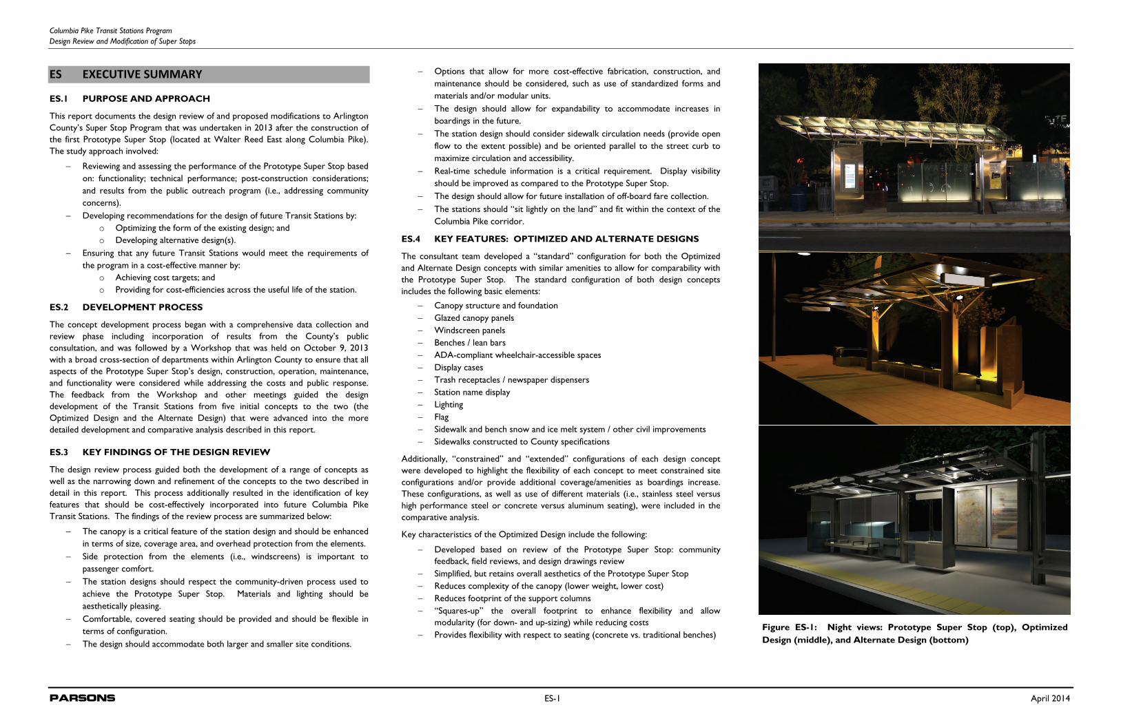
Figure ES-1: Night views: Prototype Super Stop (top), OptimizedDesign (middle), and Alternate Design (bottom)
Columbia Pike Transit Stations Program Design Review and Modification of Super Stops
Parsons ES-2 April 2014
Key characteristics of the Alternate Design include the following:
Independently developed alternative selected from an initial set of six preliminary concepts
Minimizes the footprint of the station by minimizing elements that touch the ground
Utilizes a series of standard structural shapes combined in a unique way Highly adaptable to various needs by providing the ability to support (by
suspending or cantilevering) a variety of seating, lean bars, windscreens, and other amenities from the structure itself
Structural armature provides consistent functional and aesthetic backbone Kit-of-parts system allows for comprehensive adaptation to passenger
demand and site conditions Canopy width/coverage can be calibrated to adapt to constrained site Establishes sophisticated aesthetic language with timeless design that will age
gracefully
ES.5 CONSTRUCTION COSTS
For purposes of comparative analysis, construction costs were separated into three cost categories:
Variable costs are those that are unique to each design concept and include: o Main shelter structure o Shelter amenities o Lighting
Fixed costs are assumed to be equal for all design concepts, including the Prototype Super Stop, and include:
o Electronic information system (display and information system) o Tactile warning strip o Power o Site preparation (site clearing, utility relocation) o Landscaping and site restoration o Other, including third party inspections
Implementation costs and contingencies include preliminary engineering and final design costs, construction management costs, and County program administration costs. Contingencies account for several factors, including uncertainties with respect to delivery methods for construction and to account for the conceptual nature of the design.
With respect to costs, both the Optimized and Alternate Design concepts provide significant enhancements and value to the Transit Station program as follows:
Cost reductions can be achieved by reduced complexity, reduced amount of steel, increased standardization, and increased ability to use off-site fabrication.
System-wide, costs are reduced and flexibility is increased by the “kit-of-parts” system.
Potential cost reductions are amplified if more stations are constructed as part of a single program and/or components are procured as a single package.
Lifecycle costs were also estimated, and it was determined that annual lifecycle costs were substantively the same for both the Optimized and Alternate Designs. In
addition, construction using stainless steel provides long-term life-cycle cost, durability, and aesthetic value for the County.
All cost estimates for the Prototype Super Stop were based on the design engineer’s 2006 construction cost estimated at 100% final design, escalated to 2013 dollars. The design engineer’s construction cost estimate was used because the actual construction cost from WMATA was not available at the time when this design review report was prepated. Cost estimates for the Optimized and Altnerate Design concepts were developed using 2013 dollars.
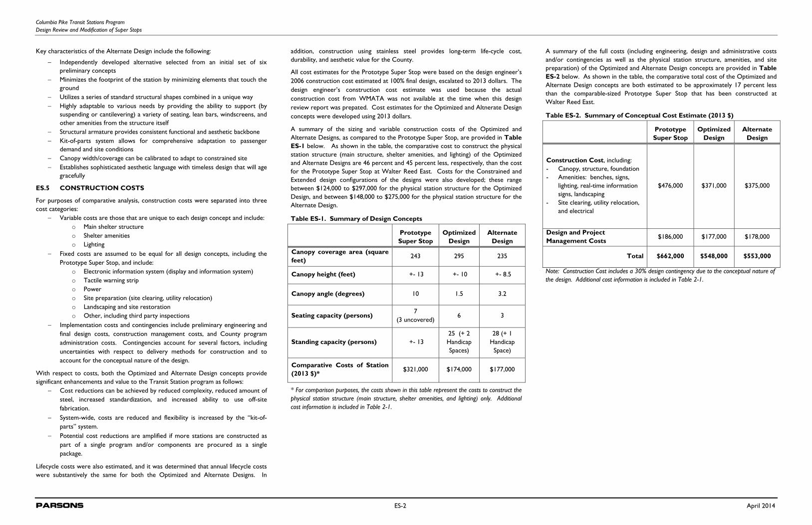
A summary of the sizing and variable construction costs of the Optimized and Alternate Designs, as compared to the Prototype Super Stop, are provided in Table ES-1 below. As shown in the table, the comparative cost to construct the physical station structure (main structure, shelter amenities, and lighting) of the Optimized and Alternate Designs are 46 percent and 45 percent less, respectively, than the cost for the Prototype Super Stop at Walter Reed East. Costs for the Constrained and Extended design configurations of the designs were also developed; these range between $124,000 to $297,000 for the physical station structure for the Optimized Design, and between $148,000 to $275,000 for the physical station structure for the Alternate Design.
Table ES-1. Summary of Design Concepts
Prototype Super Stop
Optimized Design
Alternate Design
Canopy coverage area (square feet)
243 295 235
Canopy height (feet) +- 13 +- 10 +- 8.5
Canopy angle (degrees) 10 1.5 3.2
Seating capacity (persons) 7
(3 uncovered) 6 3
Standing capacity (persons) +- 13 25 (+ 2 Handicap Spaces)
28 (+ 1 Handicap
Space)
Comparative Costs of Station (2013 $)*
$321,000 $174,000 $177,000
* For comparison purposes, the costs shown in this table represent the costs to construct the physical station structure (main structure, shelter amenities, and lighting) only. Additional cost information is included in Table 2-1.
A summary of the full costs (including engineering, design and administrative costs and/or contingencies as well as the physical station structure, amenities, and site preparation) of the Optimized and Alternate Design concepts are provided in Table ES-2 below. As shown in the table, the comparative total cost of the Optimized and Alternate Design concepts are both estimated to be approximately 17 percent less than the comparable-sized Prototype Super Stop that has been constructed at Walter Reed East.
Table ES-2. Summary of Conceptual Cost Estimate (2013 $)
Prototype Super Stop
Optimized Design
Alternate Design
Construction Cost, including: - Canopy, structure, foundation - Amenities: benches, signs,
lighting, real-time information signs, landscaping
- Site clearing, utility relocation, and electrical
$476,000 $371,000 $375,000
Design and Project Management Costs
$186,000 $177,000 $178,000
Total $662,000 $548,000 $553,000
Note: Construction Cost includes a 30% design contingency due to the conceptual nature of the design. Additional cost information is included in Table 2-1.
Columbia Pike Transit Stations Program Design Review and Modification of Super Stops
Parsons i April 2014
TABLE OF CONTENTS
EXECUTIVE SUMMARY .............................................................................................................................................................. ES-1
SECTION 1.0 INTRODUCTION 1.1 Project Background............................................................................................................................................................................... 1 1.2 Study Approach: Overview................................................................................................................................................................ 1 1.3 Concept Development Process: Overview ................................................................................................................................... 2 1.4 Organization of this Report ................................................................................................................................................................ 2
SECTION 2.0 COMPARATIVE ANALYSIS OF DESIGN CONCEPTS 2.1 Standard Configuration of Design Concepts .................................................................................................................................. 3 2.1.1 Optimized Design - Standard ................................................................................................................................................. 3 2.1.2 Alternate Design - Standard .................................................................................................................................................. 5 2.2 Constrained Configuration of Design Concepts ........................................................................................................................... 7 2.2.1 Optimized Design - Constrained .......................................................................................................................................... 7 2.2.2 Alternate Design - Standard .................................................................................................................................................. 9 2.3 Optional Materials / Configurations ................................................................................................................................................ 11 2.3.1 Optimized Design - Options ................................................................................................................................................ 11 2.3.2 Alternate Design - Options ................................................................................................................................................. 12 2.4 Conceptual Cost Comparison ......................................................................................................................................................... 13 2.4.1 Design Elements ...................................................................................................................................................................... 13 2.4.2 Procurement Elements .......................................................................................................................................................... 13 2.5 Construction Costs ............................................................................................................................................................................ 14 2.6 Life Cycle Costs ................................................................................................................................................................................... 14 2.7 Evaluation Matrix ................................................................................................................................................................................. 14
SECTION 3.0 STUDY PROCESS 3.1 Review of Prototype Super Stop ..................................................................................................................................................... 16 3.2 Incorporation of Results from County’s Public Consultation .................................................................................................. 17 3.3 Design Evaluation of Prototype Super Stop .................................................................................................................................. 18 3.4 Alternative Design Development and Cost/Benefit Analysis .................................................................................................... 19 3.5 Proposed Design Modifications and Concept Design Plans ...................................................................................................... 19
SECTION 4.0 DESIGN CRITERIA
SECTION 5.0 ALTERNATE DESIGN CONCEPTS CONSIDERED 5.1 Alternate Design Concept I .............................................................................................................................................................. 20 5.2 Alternate Design Concept II ............................................................................................................................................................. 20 5.3 Alternate Design Concept III ............................................................................................................................................................ 21 5.4 Alternate Design Concept IV ........................................................................................................................................................... 21 5.5 Alternate Design Concept V ............................................................................................................................................................ 21 5.6 Alternate Design Concept VI ........................................................................................................................................................... 22 5.7 County Feedback ................................................................................................................................................................................. 22
SECTION 6.0 REFINED CONCEPTS 6.1 Optimized Design (Draft) .................................................................................................................................................................. 23 6.2 Alternate Design 1 (Draft) ................................................................................................................................................................ 25 6.3 Alternate Design II .............................................................................................................................................................................. 27
SECTION 7.0 CONCEPTS TO MOVE FORWARD 7.1 County Feedback ................................................................................................................................................................................. 29 7.2 Outcome ............................................................................................................................................................................................... 29
FIGURES Figure ES-1 Night Views: Prototype Super Stop, Optimized Design, and Alternate Design .............................................. ES-1 Figure 1-1 Prototype Super Stop at Walter Reed East ....................................................................................................................... 1 Figure 1-2 Concept Development Process: Overview ...................................................................................................................... 2 Figure 2-1 Optimized Design – Standard: Elevation View ................................................................................................................ 3 Figure 2-2 Optimized Design – Standard: Plan View .......................................................................................................................... 3 Figure 2-3 Optimized Design – Standard: Rendered Views (Night Lighting and Day Lighting) ............................................... 4 Figure 2-4 Optimized Design – Standard: Cross-section View ....................................................................................................... 4 Figure 2-5 Alternate Design – Standard: Rendered View .................................................................................................................. 5 Figure 2-6 Alternate Design – Standard: Elevation View .................................................................................................................... 5 Figure 2-7 Alternate Design – Standard: Plan View ............................................................................................................................. 5 Figure 2-8 Alternate Design – Standard: Rendered View (Night Lighting) .................................................................................... 6 Figure 2-9 Alternate Design – Standard: Cross-section View ........................................................................................................... 6 Figure 2-10 Optimized Design – Constrained: Elevation View ....................................................................................................... 7 Figure 2-11 Optimized Design – Constrained: Plan View ................................................................................................................. 7 Figure 2-12 Optimized Design – Constrained: Cross-section View .............................................................................................. 8 Figure 2-13 Optimized Design – Constrained: Rendered View ...................................................................................................... 8 Figure 2-14 Alternate Design – Constrained: Elevation View ........................................................................................................... 9 Figure 2-15 Alternate Design – Constrained: Plan View .................................................................................................................... 9 Figure 2-16 Alternate Design – Constrained: Cross-section View ................................................................................................ 10 Figure 2-17 Alternate Design – Constrained: Rendered View ....................................................................................................... 10 Figure 2-18 Optimized Design – Optional Extension Views ........................................................................................................... 11 Figure 2-19 Alternate Design – Optional Extension Views ............................................................................................................. 12 Figure 2-20 Alternate Design – Extended: Cross-section View of Expanded Canopy ............................................................ 13 Figure 3-1 Images of Prototype Super Stop Elements at Walter Reed East ................................................................................ 18 Figure 5-1 Alternate Design Concept 1 ................................................................................................................................................ 20 Figure 5-2 Alternate Design Concept 1I .............................................................................................................................................. 20 Figure 5-3 Alternate Design Concept 1II ............................................................................................................................................. 21 Figure 5-4 Alternate Design Concept 1V ............................................................................................................................................. 21 Figure 5-5 Alternate Design Concept V ............................................................................................................................................... 21 Figure 5-6 Alternate Design Concept VI .............................................................................................................................................. 22 Figure 6-1 Draft Optimized Design Rendered View I ....................................................................................................................... 23 Figure 6-2 Draft Optimized Design Rendered View 2 ...................................................................................................................... 23 Figure 6-3 Draft Optimized Design Kit-of-Parts ................................................................................................................................ 23 Figure 6-4 Draft Optimized Design Plan and Elevation Views ........................................................................................................ 24 Figure 6-5 Draft Alternate Design 1 Rendered View 1 .................................................................................................................... 25 Figure 6-6 Draft Alternate Design 1 Rendered View 2 .................................................................................................................... 25 Figure 6-7 Draft Alternate Design 1 Kit-of-Parts ............................................................................................................................... 25 Figure 6-8 Draft Alternate Design 1 Plan and Elevation Views ....................................................................................................... 26 Figure 6-9 Alternate Design II Rendered View I ................................................................................................................................. 27 Figure 6-10 Alternate Design II Rendered View 2 ............................................................................................................................. 27 Figure 6-11 Alternate Design II Cross-section View ......................................................................................................................... 27 Figure 6-12 Alternate Design II Kit-of-Parts ........................................................................................................................................ 27 Figure 6-13 Alternate Design II Plan and Elevation Views ................................................................................................................ 28
TABLES Table ES-1 Summary of Design Concepts ........................................................................................................................................ ES-2 Table ES-2 Summary of Conceptual Cost Estimate (2013 $) .................................................................................................... ES-2 Table 2-1 Construction Costs ................................................................................................................................................................ 15 Table 2-2 Evaluation Matrix ..................................................................................................................................................................... 14 Table 3-1 Summary of Survey Results ................................................................................................................................................... 17 Table 3-2 Key Findings of Workshop ................................................................................................................................................... 18 Table 3-3 Options for Proceeding with Transit Station Design ..................................................................................................... 19
Columbia Pike Transit Stations Program Design Review and Modification of Super Stops
Parsons 1 April 2014
1.0 INTRODUCTION
1.1 PROJECT BACKGROUND
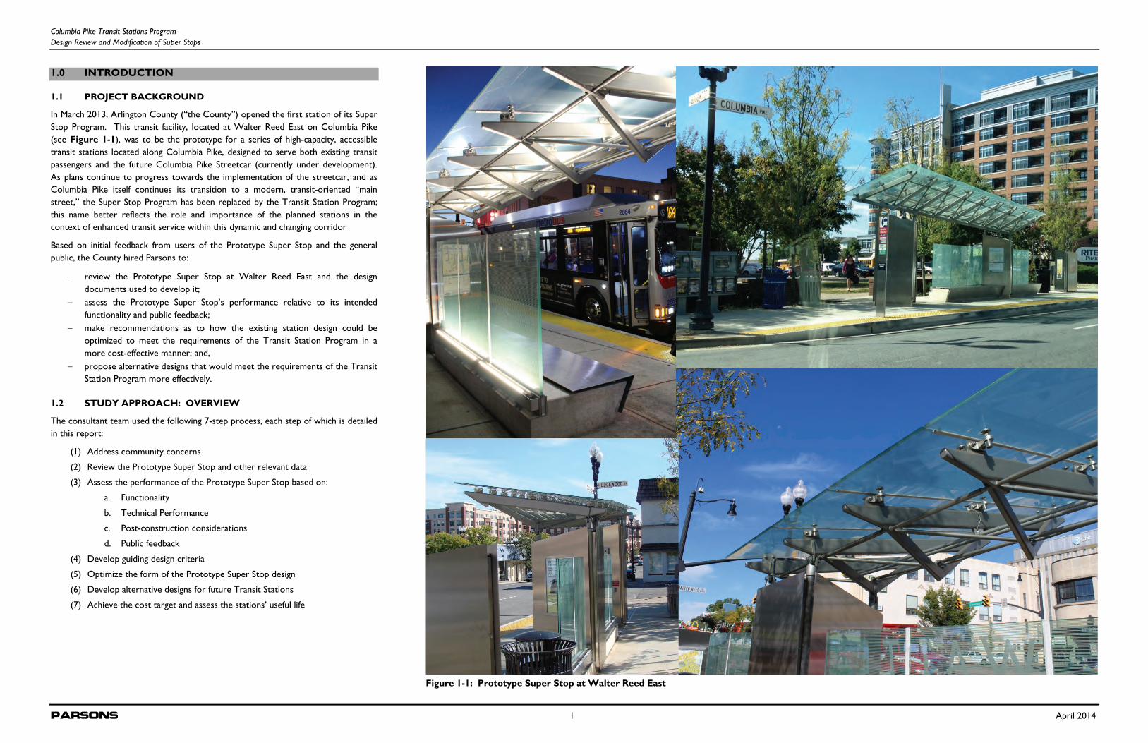
In March 2013, Arlington County (“the County”) opened the first station of its Super Stop Program. This transit facility, located at Walter Reed East on Columbia Pike (see Figure 1-1), was to be the prototype for a series of high-capacity, accessible transit stations located along Columbia Pike, designed to serve both existing transit passengers and the future Columbia Pike Streetcar (currently under development). As plans continue to progress towards the implementation of the streetcar, and as Columbia Pike itself continues its transition to a modern, transit-oriented “main street,” the Super Stop Program has been replaced by the Transit Station Program; this name better reflects the role and importance of the planned stations in the context of enhanced transit service within this dynamic and changing corridor
Based on initial feedback from users of the Prototype Super Stop and the general public, the County hired Parsons to:
review the Prototype Super Stop at Walter Reed East and the design documents used to develop it;
assess the Prototype Super Stop’s performance relative to its intended functionality and public feedback;
make recommendations as to how the existing station design could be optimized to meet the requirements of the Transit Station Program in a more cost-effective manner; and,
propose alternative designs that would meet the requirements of the Transit Station Program more effectively.
1.2 STUDY APPROACH: OVERVIEW
The consultant team used the following 7-step process, each step of which is detailed in this report:
(1) Address community concerns
(2) Review the Prototype Super Stop and other relevant data
(3) Assess the performance of the Prototype Super Stop based on:
a. Functionality
b. Technical Performance
c. Post-construction considerations
d. Public feedback
(4) Develop guiding design criteria
(5) Optimize the form of the Prototype Super Stop design
(6) Develop alternative designs for future Transit Stations
(7) Achieve the cost target and assess the stations’ useful life
Figure 1-1: Prototype Super Stop at Walter Reed East
Columbia Pike Transit Stations Program Design Review and Modification of Super Stops
Parsons 2 April 2014
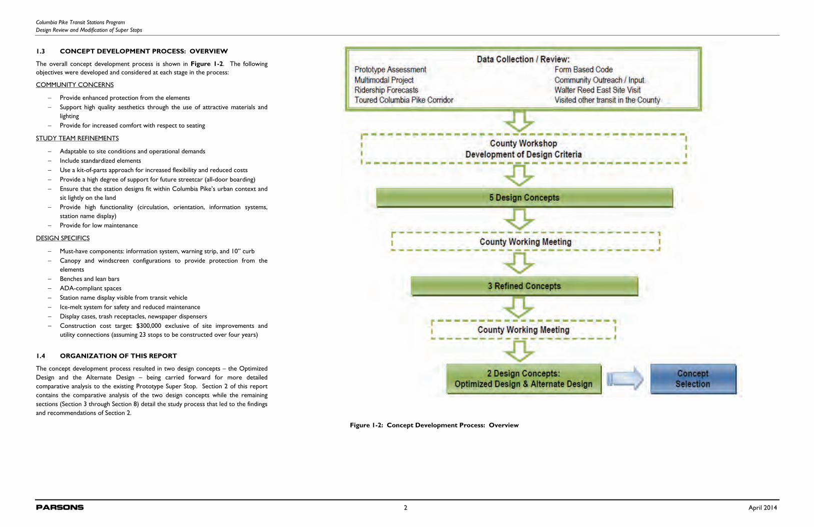
1.3 CONCEPT DEVELOPMENT PROCESS: OVERVIEW
The overall concept development process is shown in Figure 1-2. The following objectives were developed and considered at each stage in the process:
COMMUNITY CONCERNS
Provide enhanced protection from the elements Support high quality aesthetics through the use of attractive materials and
lighting Provide for increased comfort with respect to seating
STUDY TEAM REFINEMENTS
Adaptable to site conditions and operational demands Include standardized elements Use a kit-of-parts approach for increased flexibility and reduced costs Provide a high degree of support for future streetcar (all-door boarding) Ensure that the station designs fit within Columbia Pike’s urban context and
sit lightly on the land Provide high functionality (circulation, orientation, information systems,
station name display) Provide for low maintenance
DESIGN SPECIFICS
Must-have components: information system, warning strip, and 10” curb Canopy and windscreen configurations to provide protection from the
elements Benches and lean bars ADA-compliant spaces Station name display visible from transit vehicle Ice-melt system for safety and reduced maintenance Display cases, trash receptacles, newspaper dispensers Construction cost target: $300,000 exclusive of site improvements and
utility connections (assuming 23 stops to be constructed over four years)
1.4 ORGANIZATION OF THIS REPORT
The concept development process resulted in two design concepts – the Optimized Design and the Alternate Design – being carried forward for more detailed comparative analysis to the existing Prototype Super Stop. Section 2 of this report contains the comparative analysis of the two design concepts while the remaining sections (Section 3 through Section 8) detail the study process that led to the findings and recommendations of Section 2.
Figure 1-2: Concept Development Process: Overview
Columbia Pike Transit Stations Program Design Review and Modification of Super Stops
Parsons 3 April 2014
2.0 COMPARATIVE ANALYSIS OF DESIGN CONCEPTS
2.1 STANDARD CONFIGURATION OF DESIGN CONCEPTS
To allow for an “apples to apples” comparison to the Prototype Super Stop located at Walter Reed East, each of the design alternatives was sized to the approximate coverage of the Prototype Super Stop and was assumed to have similar amenities. This configuration of each design concept was termed the “standard” and is described in detail below. The standard configuration of both design concepts includes the following basic elements:
Canopy structure and foundation Use of stainless steel throughout and glazed canopy panels Windscreen panels Benches / lean bars ADA-compliant wheelchair-accessible spaces Display cases Trash receptacles / newspaper dispensers Station name display Lighting Flag Sidewalk and bench snow and ice melt system / other civil improvements Sidewalks constructed to County specifications
Note that all figures in this report are graphic representations at the conceptual level and do not reflect detailed design features; for example, there would be no gaps between the glass panels or roof panels in the final designs. Additionally, all structural member sizes were validated by structural analysis, considering applicable codes as well as wind, rain, and snow conditions. Analysis was commensurate with the level of design detail and the level of project development required herein.
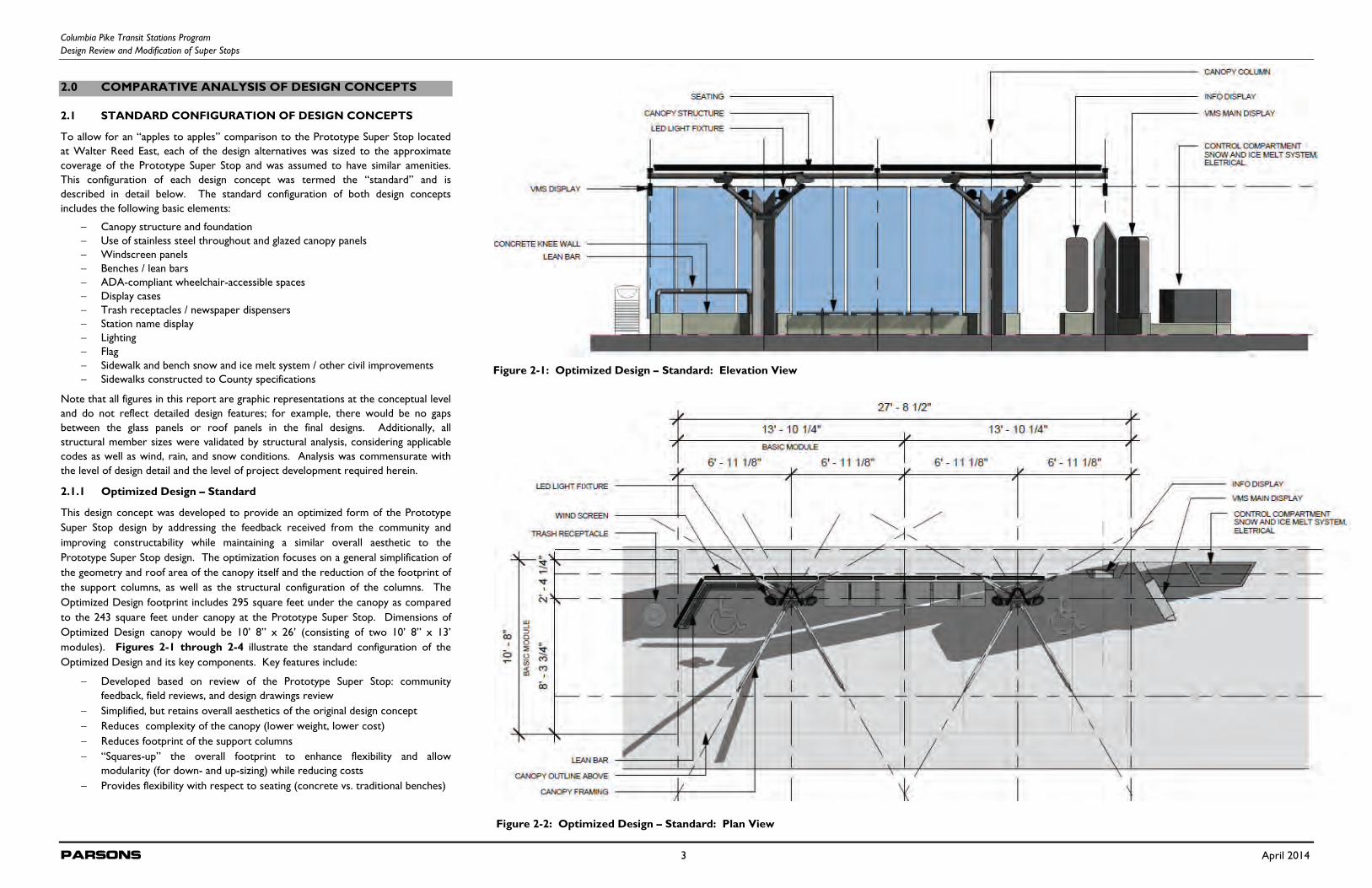
2.1.1 Optimized Design – Standard
This design concept was developed to provide an optimized form of the Prototype Super Stop design by addressing the feedback received from the community and improving constructability while maintaining a similar overall aesthetic to the Prototype Super Stop design. The optimization focuses on a general simplification of the geometry and roof area of the canopy itself and the reduction of the footprint of the support columns, as well as the structural configuration of the columns. The Optimized Design footprint includes 295 square feet under the canopy as compared to the 243 square feet under canopy at the Prototype Super Stop. Dimensions of Optimized Design canopy would be 10’ 8” x 26’ (consisting of two 10’ 8” x 13’ modules). Figures 2-1 through 2-4 illustrate the standard configuration of the Optimized Design and its key components. Key features include:
Developed based on review of the Prototype Super Stop: community feedback, field reviews, and design drawings review
Simplified, but retains overall aesthetics of the original design concept Reduces complexity of the canopy (lower weight, lower cost) Reduces footprint of the support columns “Squares-up” the overall footprint to enhance flexibility and allow
modularity (for down- and up-sizing) while reducing costs Provides flexibility with respect to seating (concrete vs. traditional benches)
Figure 2-2: Optimized Design – Standard: Plan View
Figure 2-1: Optimized Design – Standard: Elevation View
Columbia Pike Transit Stations Program Design Review and Modification of Super Stops
Parsons 4 April 2014
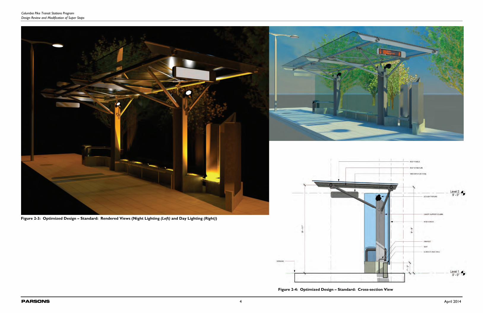
Figure 2-4: Optimized Design – Standard: Cross-section View
Figure 2-3: Optimized Design – Standard: Rendered Views (Night Lighting (Left) and Day Lighting (Right))
Columbia Pike Transit Stations Program Design Review and Modification of Super Stops
Parsons 5 April 2014
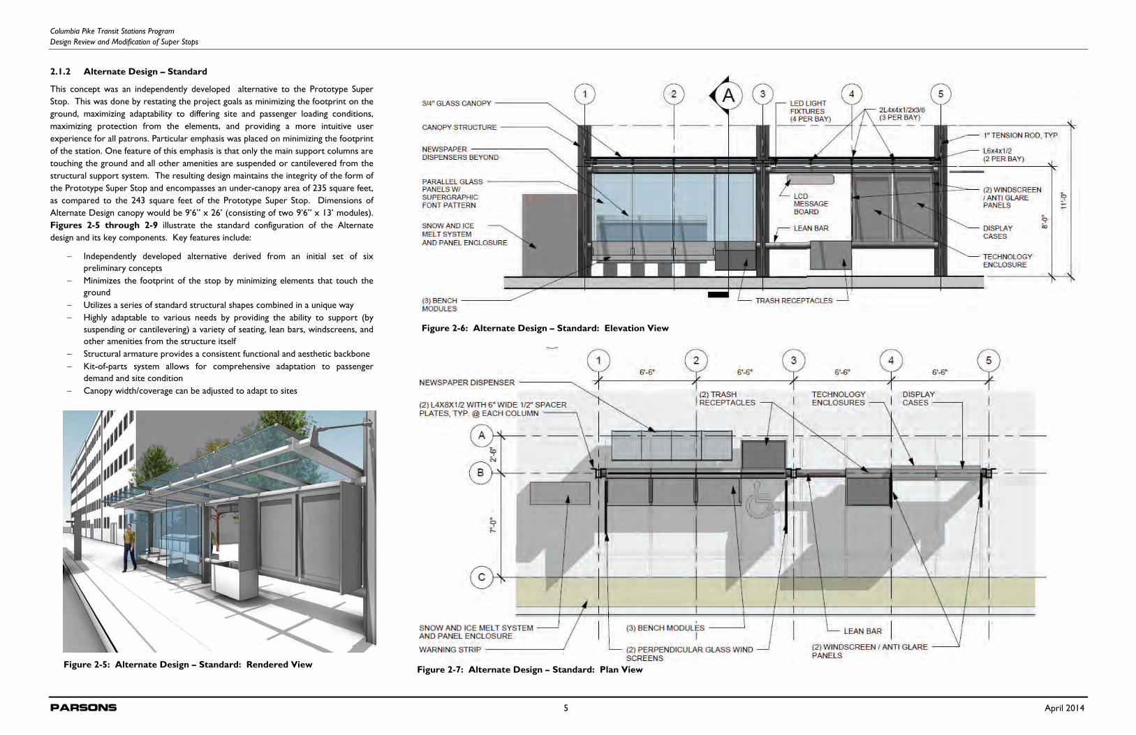
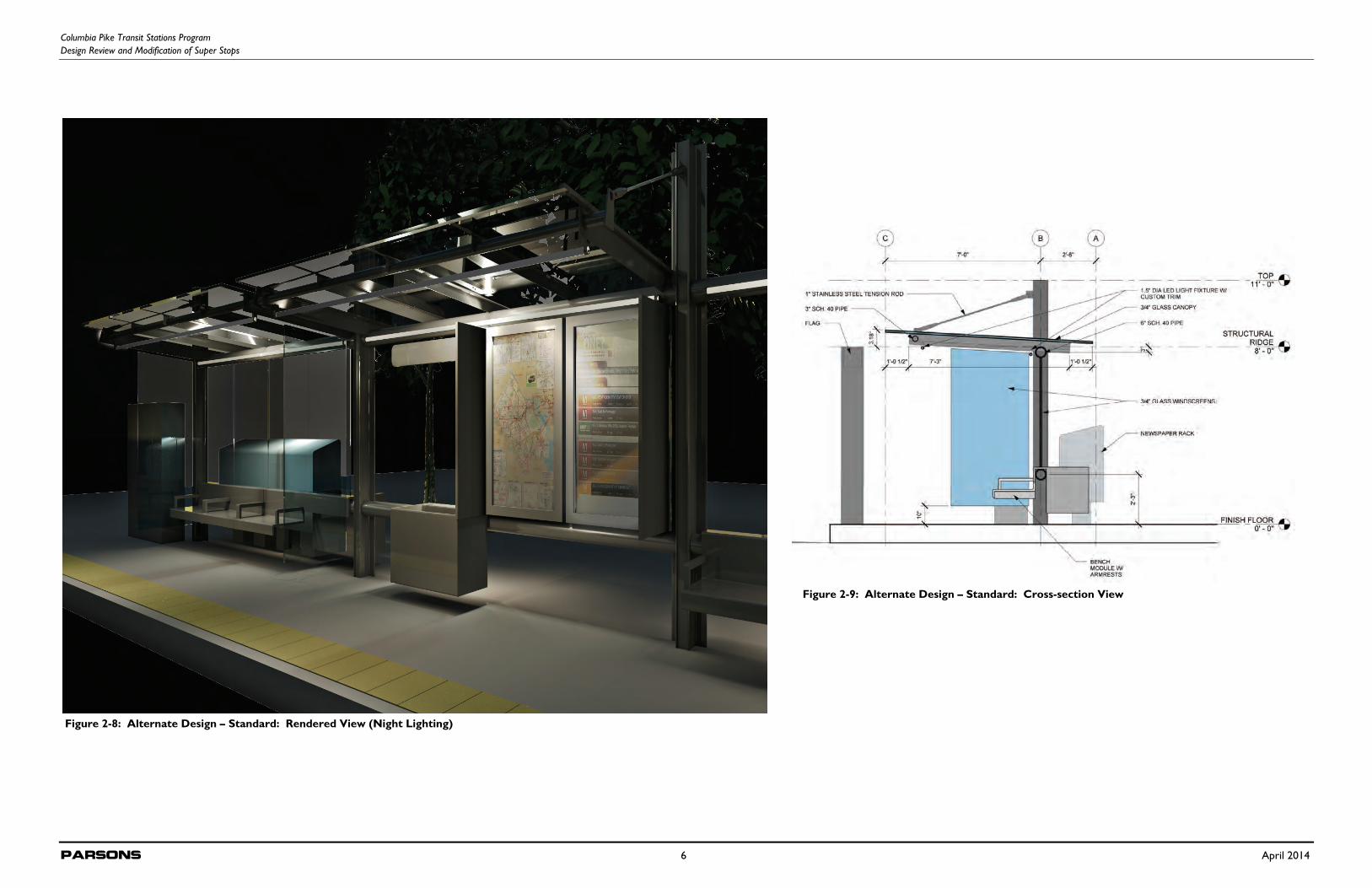
2.1.2 Alternate Design – Standard
This concept was an independently developed alternative to the Prototype Super Stop. This was done by restating the project goals as minimizing the footprint on the ground, maximizing adaptability to differing site and passenger loading conditions, maximizing protection from the elements, and providing a more intuitive user experience for all patrons. Particular emphasis was placed on minimizing the footprint of the station. One feature of this emphasis is that only the main support columns are touching the ground and all other amenities are suspended or cantilevered from the structural support system. The resulting design maintains the integrity of the form of the Prototype Super Stop and encompasses an under-canopy area of 235 square feet, as compared to the 243 square feet of the Prototype Super Stop. Dimensions of Alternate Design canopy would be 9’6” x 26’ (consisting of two 9’6” x 13’ modules). Figures 2-5 through 2-9 illustrate the standard configuration of the Alternate design and its key components. Key features include:
Independently developed alternative derived from an initial set of six preliminary concepts
Minimizes the footprint of the stop by minimizing elements that touch the ground
Utilizes a series of standard structural shapes combined in a unique way Highly adaptable to various needs by providing the ability to support (by
suspending or cantilevering) a variety of seating, lean bars, windscreens, and other amenities from the structure itself
Structural armature provides a consistent functional and aesthetic backbone Kit-of-parts system allows for comprehensive adaptation to passenger
demand and site condition Canopy width/coverage can be adjusted to adapt to sites
Figure 2-7: Alternate Design – Standard: Plan View
Figure 2-6: Alternate Design – Standard: Elevation View
Figure 2-5: Alternate Design – Standard: Rendered View
Columbia Pike Transit Stations Program Design Review and Modification of Super Stops
Parsons 6 April 2014
Figure 2-9: Alternate Design – Standard: Cross-section View
Figure 2-8: Alternate Design – Standard: Rendered View (Night Lighting)
Columbia Pike Transit Stations Program Design Review and Modification of Super Stops
Parsons 7 April 2014
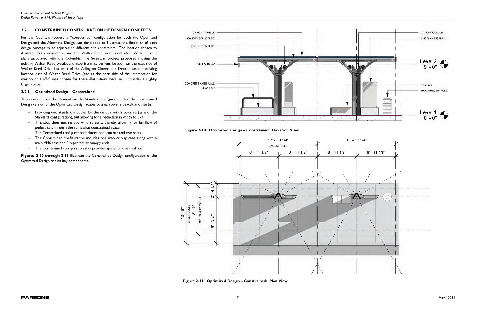
2.2 CONSTRAINED CONFIGURATION OF DESIGN CONCEPTS
Per the County’s request, a “constrained” configuration for both the Optimized Design and the Alternate Design was developed to illustrate the flexibility of each design concept to be adjusted to different site constraints. The location chosen to illustrate this configuration was the Walter Reed westbound site. While current plans associated with the Columbia Pike Streetcar project proposed moving the existing Walter Reed westbound stop from its current location on the east side of Walter Reed Drive just west of the Arlington Cinema and Drafthouse, the existing location east of Walter Reed Drive (and at the near side of the intersection for westbound traffic) was chosen for these illustrations because it provides a slightly larger space.
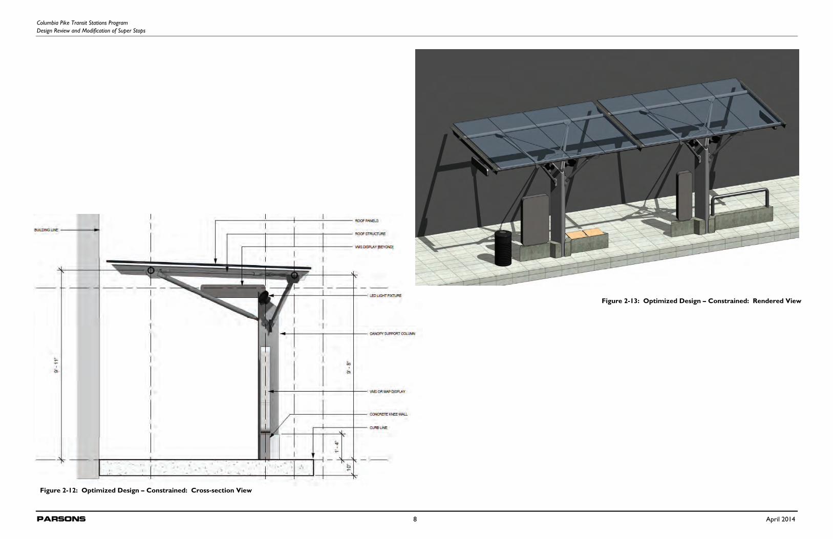
2.2.1 Optimized Design – Constrained
This concept uses the elements in the Standard configuration, but the Constrained Design version of the Optimized Design adapts to a narrower sidewalk and site by:
Providing two standard modules for the canopy with 2 columns (as with the Standard configuration), but allowing for a reduction in width to 8’-7”
This stop does not include wind screens, thereby allowing for full flow of pedestrians through the somewhat constrained space
The Constrained configuration includes one lean bar and two seats The Constrained configuration includes one map display case along with a
main VMS case and 2 repeaters at canopy ends The Constrained configuration also provides space for one trash can
Figures 2-10 through 2-13 illustrate the Constrained Design configuration of the Optimized Design and its key components.
Figure 2-10: Optimized Design – Constrained: Elevation View
Figure 2-11: Optimized Design – Constrained: Plan View
Columbia Pike Transit Stations Program Design Review and Modification of Super Stops
Parsons 8 April 2014
Figure 2-13: Optimized Design – Constrained: Rendered View
Figure 2-12: Optimized Design – Constrained: Cross-section View
Columbia Pike Transit Stations Program Design Review and Modification of Super Stops
Parsons 9 April 2014
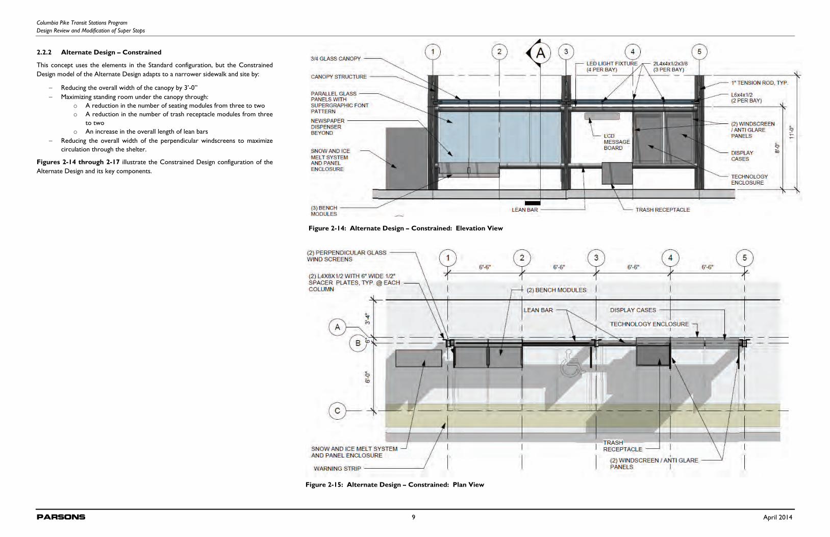
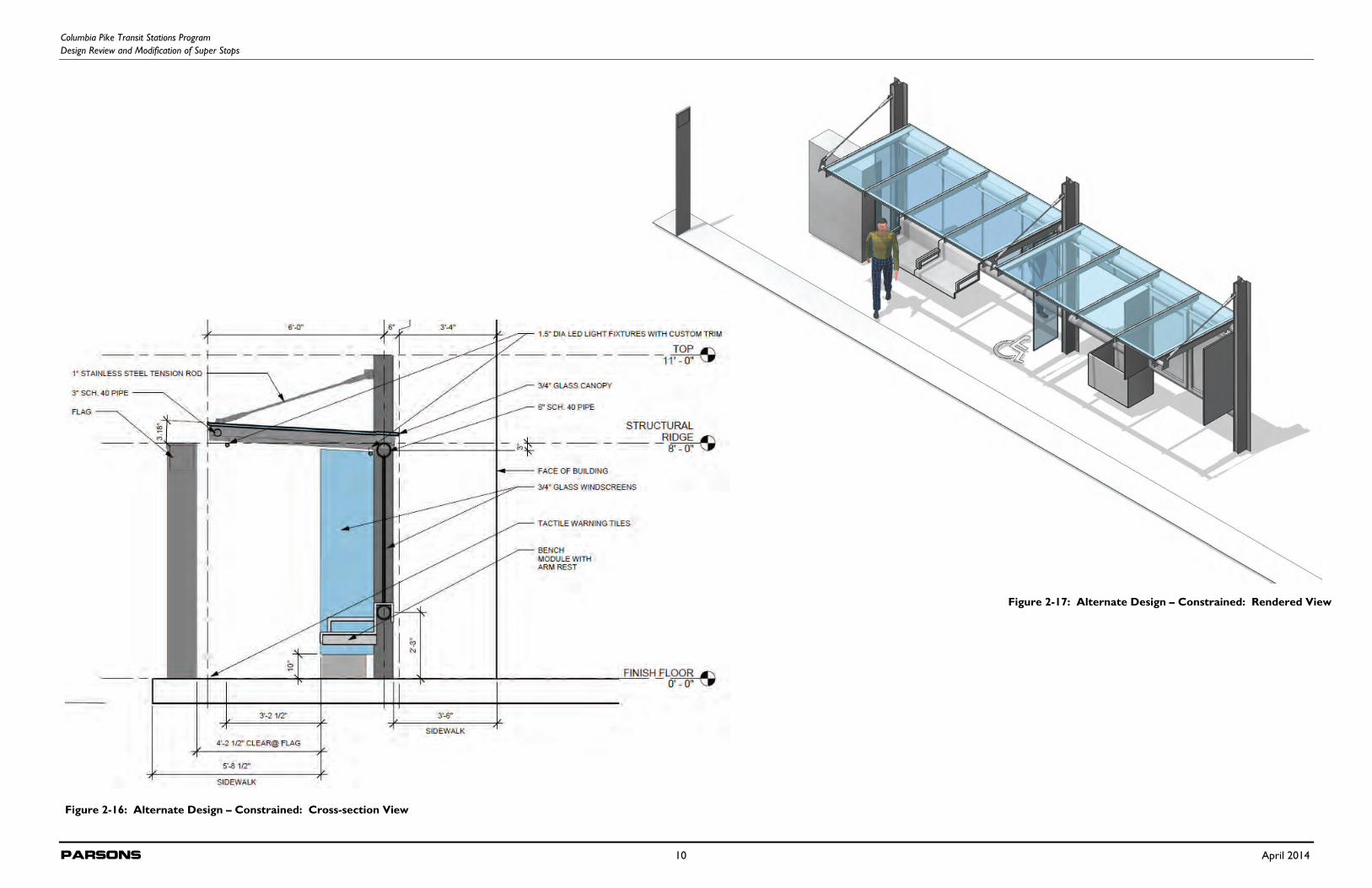
2.2.2 Alternate Design – Constrained
This concept uses the elements in the Standard configuration, but the Constrained Design model of the Alternate Design adapts to a narrower sidewalk and site by:
Reducing the overall width of the canopy by 3’-0” Maximizing standing room under the canopy through:
o A reduction in the number of seating modules from three to two o A reduction in the number of trash receptacle modules from three
to two o An increase in the overall length of lean bars
Reducing the overall width of the perpendicular windscreens to maximize circulation through the shelter.
Figures 2-14 through 2-17 illustrate the Constrained Design configuration of the Alternate Design and its key components.
Figure 2-14: Alternate Design – Constrained: Elevation View
Figure 2-15: Alternate Design – Constrained: Plan View
Columbia Pike Transit Stations Program Design Review and Modification of Super Stops
Parsons 10 April 2014
Figure 2-16: Alternate Design – Constrained: Cross-section View
Figure 2-17: Alternate Design – Constrained: Rendered View
Columbia Pike Transit Stations Program Design Review and Modification of Super Stops
Parsons 11 April 2014
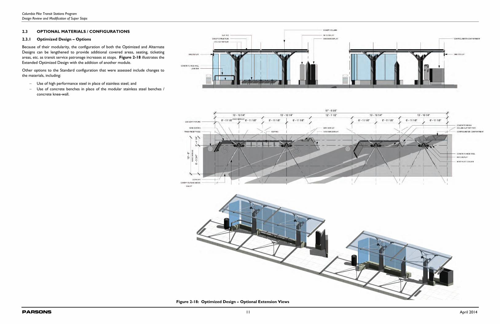
2.3 OPTIONAL MATERIALS / CONFIGURATIONS
2.3.1 Optimized Design – Options
Because of their modularity, the configuration of both the Optimized and Alternate Designs can be lengthened to provide additional covered areas, seating, ticketing areas, etc. as transit service patronage increases at stops. Figure 2-18 illustrates the Extended Optimized Design with the addition of another module.
Other options to the Standard configuration that were assessed include changes to the materials, including:
Use of high performance steel in place of stainless steel; and Use of concrete benches in place of the modular stainless steel benches /
concrete knee-wall.
Figure 2-18: Optimized Design – Optional Extension Views
Columbia Pike Transit Stations Program Design Review and Modification of Super Stops
Parsons 12 April 2014
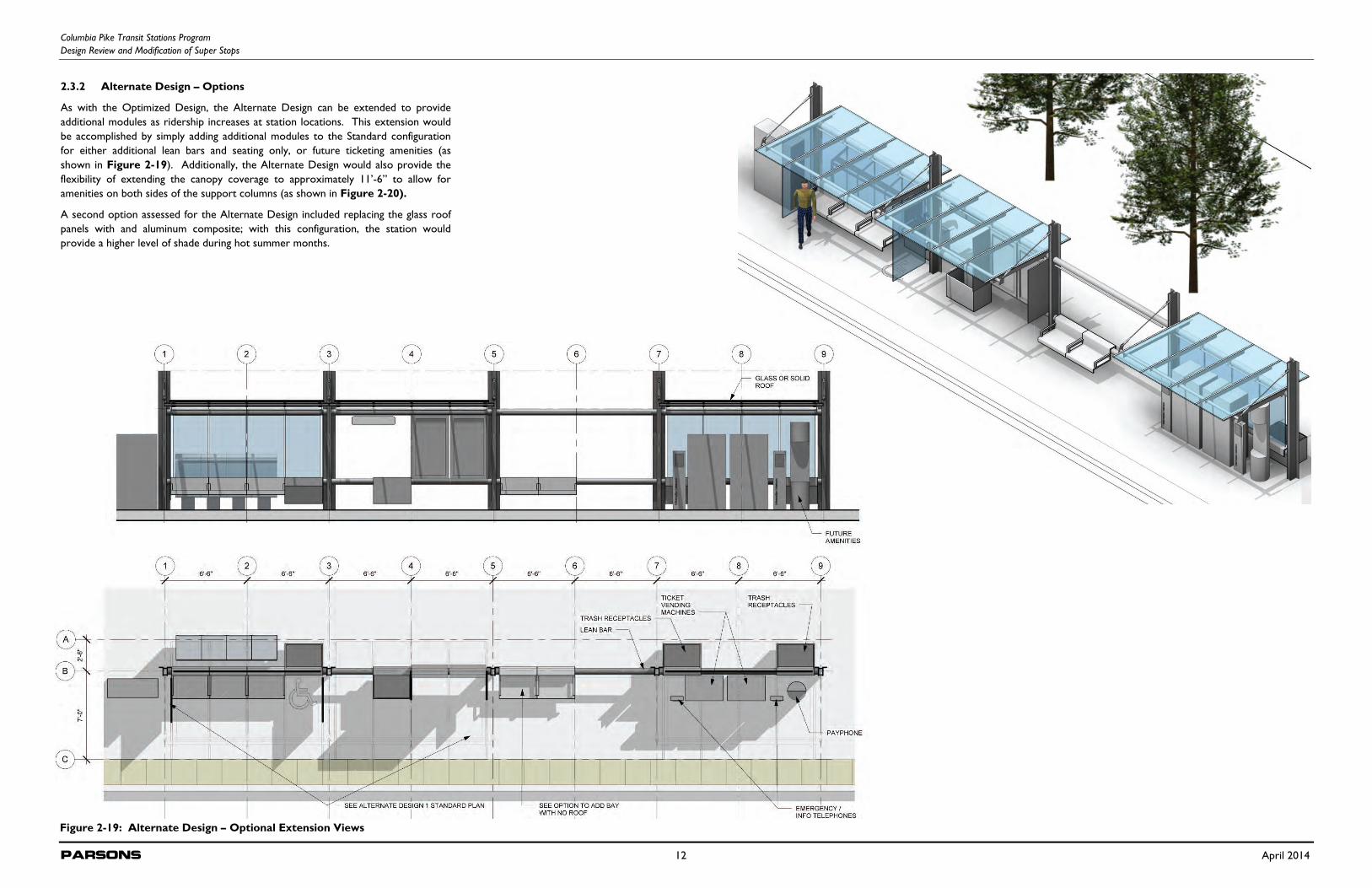
2.3.2 Alternate Design – Options
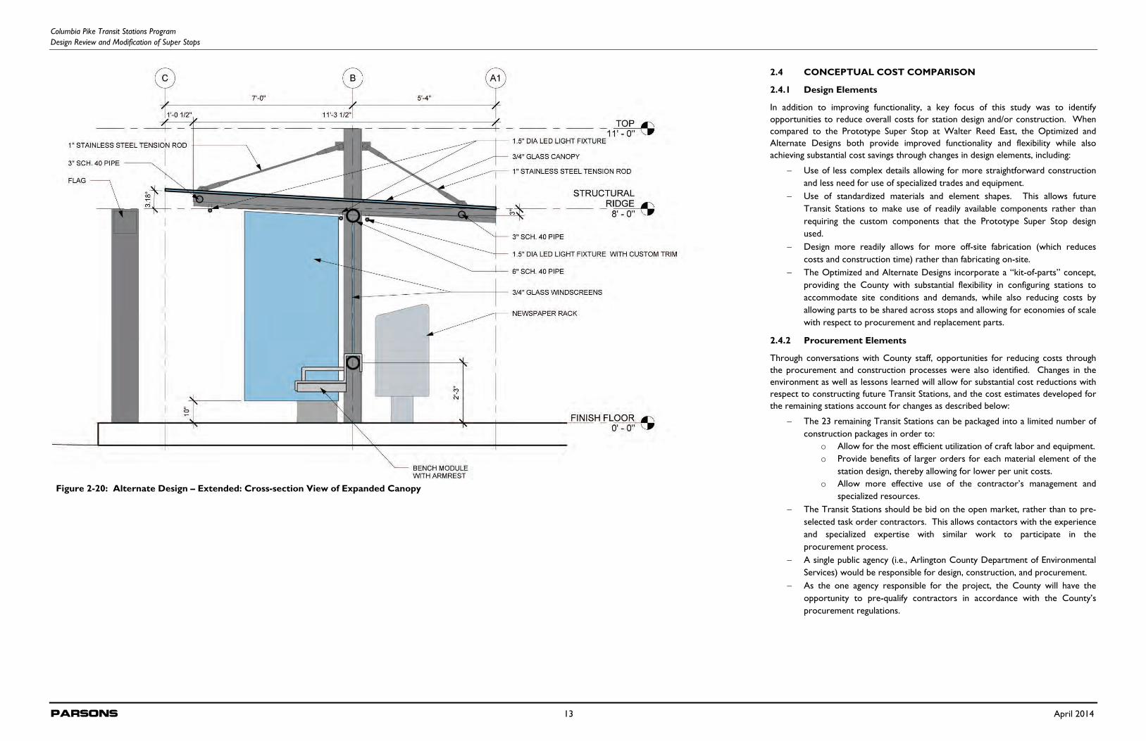
As with the Optimized Design, the Alternate Design can be extended to provide additional modules as ridership increases at station locations. This extension would be accomplished by simply adding additional modules to the Standard configuration for either additional lean bars and seating only, or future ticketing amenities (as shown in Figure 2-19). Additionally, the Alternate Design would also provide the flexibility of extending the canopy coverage to approximately 11’-6” to allow for amenities on both sides of the support columns (as shown in Figure 2-20).
A second option assessed for the Alternate Design included replacing the glass roof panels with and aluminum composite; with this configuration, the station would provide a higher level of shade during hot summer months.
Figure 2-19: Alternate Design – Optional Extension Views
Columbia Pike Transit Stations Program Design Review and Modification of Super Stops
Parsons 13 April 2014
2.4 CONCEPTUAL COST COMPARISON
2.4.1 Design Elements
In addition to improving functionality, a key focus of this study was to identify opportunities to reduce overall costs for station design and/or construction. When compared to the Prototype Super Stop at Walter Reed East, the Optimized and Alternate Designs both provide improved functionality and flexibility while also achieving substantial cost savings through changes in design elements, including:
Use of less complex details allowing for more straightforward construction and less need for use of specialized trades and equipment.
Use of standardized materials and element shapes. This allows future Transit Stations to make use of readily available components rather than requiring the custom components that the Prototype Super Stop design used.
Design more readily allows for more off-site fabrication (which reduces costs and construction time) rather than fabricating on-site.
The Optimized and Alternate Designs incorporate a “kit-of-parts” concept, providing the County with substantial flexibility in configuring stations to accommodate site conditions and demands, while also reducing costs by allowing parts to be shared across stops and allowing for economies of scale with respect to procurement and replacement parts.
2.4.2 Procurement Elements
Through conversations with County staff, opportunities for reducing costs through the procurement and construction processes were also identified. Changes in the environment as well as lessons learned will allow for substantial cost reductions with respect to constructing future Transit Stations, and the cost estimates developed for the remaining stations account for changes as described below:
The 23 remaining Transit Stations can be packaged into a limited number of construction packages in order to:
o Allow for the most efficient utilization of craft labor and equipment. o Provide benefits of larger orders for each material element of the
station design, thereby allowing for lower per unit costs. o Allow more effective use of the contractor’s management and
specialized resources. The Transit Stations should be bid on the open market, rather than to pre-
selected task order contractors. This allows contactors with the experience and specialized expertise with similar work to participate in the procurement process.
A single public agency (i.e., Arlington County Department of Environmental Services) would be responsible for design, construction, and procurement.
As the one agency responsible for the project, the County will have the opportunity to pre-qualify contractors in accordance with the County’s procurement regulations.
Figure 2-20: Alternate Design – Extended: Cross-section View of Expanded Canopy
Columbia Pike Transit Stations Program Design Review and Modification of Super Stops
Parsons 14 April 2014
2.5 CONSTRUCTION COSTS
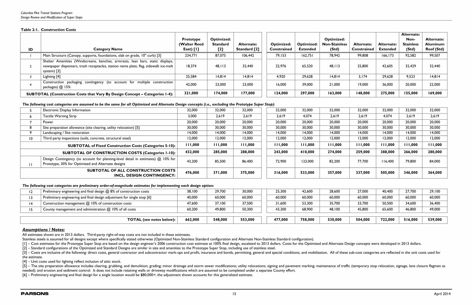
In order to facilitate comparisons across the design concepts, total estimated costs (which are summarized in Table 2-1) were grouped into three categories: 1) construction costs that varied by concept, 2) construction costs that did not vary across concepts, and 3) implementation costs and contingencies. The variable construction costs included main structure costs (comprised of the canopy, supports, foundations, slab on grade, and 10-inch curb), shelter amenity costs (comprised of windscreens, benches, armrests, lean bars, static displays, newspaper dispensers, trash receptacles, station name plates, flag, and sidewalk ice-melt system), and lighting costs. Construction costs that did not vary by concept include the electronic information system (display and information system), tactile warning strips, power connections, site preparation (including site clearing and utility relocation), landscaping and site restoration, and third party inspections. Implementation costs include preliminary engineering and final design costs, construction management and County program administration costs, as well as contingencies. Contingencies account for several factors, including uncertainties with respect to delivery methods for construction as well as the size of construction packages (i.e., how many stations would be constructed in a single package), as well as uncertainties that result when cost estimates are based on concepts rather than final designs. The cost estimates do account for the reduced complexities of the proposed concepts as well as the “kit-of-parts” approach as described in Section 2.4.1.
As Table 2-1 shows, the full cost (including engineering, design and administrative costs and/or contingencies) of the Standard configurations of the Optimized and the Alternate Designs are each estimated to be approximately 17 percent less than the comparably-sized Prototype Super Stop that has been constructed at Walter Reed East. For those cost elements that vary by design concept (main structure, shelter amenities, and lighting) and are, therefore, most affected by the changes incorporated into the new design concepts, the costs of the Optimized and Alternate Designs are 46% and 45% lower, respectively, than the cost for the Prototype Super Stop station at Walter Reed East. Table 2-1 also shows the estimated costs for the optional configurations for both the Optimized and the Alternate Designs, including both Constrained site and Extended site versions of each, as well as using non-stainless steel materials. In addition, a cost estimate for the Alternate Design that replaces the glass in the canopy with aluminum panels was prepared.
All cost estimates for the Prototype Super Stop were based on the design engineer’s 2006 construction cost estimated at 100% final design, escalated to 2013 dollars. The design engineer’s construction cost estimate was used because the actual construction cost from WMATA was not available at the time when this design review report was prepated. Cost estimates for the Optimized and Altnerate Design concepts were developed using 2013 dollars.
2.6 LIFE CYCLE COSTS
By providing a method for assessing the total costs of facility ownership, life cycle cost analyses allow for considering the cost implications of the lifespan of different materials, as well as potential differences in maintenance costs. The assumed lifespan of Columbia Pike Transit Stations is 80-100 years. While not directly comparable in terms of size and functionality, typical bus stop shelters have a lifespan of 20-25 years.
Other than the foundations, concrete, and steel elements, other elements of the Transit Stations will likely require replacement one or more times over the lifespan of either the Optimized or the Alternate Designs. The number of replacement cycles for these other elements over the assumed 80-year lifespan of the Transit Stations (80 years was used as a conservative figure) include:
Two replacement cycles: coated steel, glass features, snow and ice melt systems
Three replacement cycles: lighting fixtures Six to seven replacement cycles: benches, electronic displays, information
systems
Because of the similarities in footprint, materials, and maintenance, differences in life cycle costs between the Optimized and Alternate Design concepts are minor. Consideration of replacement and maintenance costs results in total life cycle costs of approximately $950,000 (net present value), of which approximately $420,000 represents costs for replacement and maintenance over the 80-year life of the station. In addition, the reduced replacement cycles for using stainless steel as opposed to performance-coated steel largely offsets the increased cost of stainless steel (difference of less than 1% of total life cycle cost). Therefore, it is recommended that stainless steel be used based on both durability and aesthetic considerations.
2.7 EVALUATION MATRIX
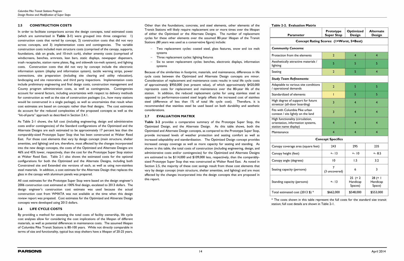
Table 2-2 provides a comparative summary of the Prototype Super Stop, the Optimized Design, and the Alternate Design. As this table shows, both the Optimized and Alternate Design concepts, as compared to the Prototype Super Stop, provide increased levels of weather protection and seating comfort as well as increased adaptability and standardization. The Optimized Design concept provides increased canopy coverage as well as more capacity for seating and standing. As shown in this table, the total costs of construction (including engineering, design, and administrative costs and/or contingencies) for the Optimized and Alternate Designs are estimated to be $114,000 and $109,000 less, respectively, than the comparably-sized Prototype Super Stop that was constructed at Walter Reed East. As noted in Section 2.5, the majority of these cost savings result from those cost elements that vary by design concept (main structure, shelter amenities, and lighting) and are most affected by the changes incorporated into the design concepts that are proposed in this report.
Table 2-2. Evaluation Matrix
Parameter Prototype Super Stop
Optimized Design
Alternate Design
Concept Rating Scores: (1=Worst, 5=Best)
Community Concerns:
Protection from the elements 2 4 4
Aesthetically attractive materials / lighting 5 5 5
Seating 2 5 4
Study Team Refinements:
Adaptable to various site conditions / operational demands 2 5 5
Standardized of elements 1 5 5
High degree of support for future streetcar (all-door boarding) 3 4 4
Fits with Columbia Pike urban context / sits lightly on the land 3 4 4
High functionality (circulation, orientation, information systems, station name display)
4 4 4
Maintenance 4 4 4
Concept Specifics
Canopy coverage area (square feet) 243 295 235
Canopy height (feet) +- 13 +- 10 +- 8.5
Canopy angle (degrees) 10 1.5 3.2
Seating capacity (persons) 7 (3 uncovered) 6 3
Standing capacity (persons) +- 13 25 (+ 2 Handicap Spaces)
28 (+ 1 Handicap
Space)
Total estimated cost (2013 $) * $662,000 $548,000 $553,000
* The costs shown in this table represent the full costs for the standard size transit station; full cost details are shown in Table 2-1.
Columbia Pike Transit Stations Program Design Review and Modification of Super Stops
Parsons 15 April 2014
Table 2-1. Construction Costs
ID Category Name
Prototype (Walter Reed
East) [1]
Optimized: Standard
[2] Alternate:
Standard [2] Optimized: Constrained
Optimized: Extended
Optimized: Non-Stainless
(Std) Alternate:
Constrained Alternate: Extended
Alternate: Non-
Stainless (Std)
Alternate: Aluminum Roof (Std)
1 Main Structure (Canopy, supports, foundations, slab on grade, 10" curb) [3] 234,771 87,075 106,442
79,153 162,751 78,942 99,808 166,173 92,582 99,507
2 Shelter Amenities (Windscreens, benches, armrests, lean bars, static displays, newspaper dispensers, trash receptacles, station name plate, flag, sidewalk ice-melt system) [3]
18,374 48,113 32,440
22,976 65,520 48,113 25,800 42,605 32,429 32,440
3 Lighting [4] 25,584 14,814 14,814
4,920 29,628 14,814 3,174 29,628 9,523 14,814
4 Construction packaging contingency (to account for multiple construction packages) @ 15%
42,000 23,000 23,000
16,000 39,000 21,000 19,000 36,000 20,000 22,000
SUBTOTAL (Construction Costs that Vary By Design Concept – Categories 1-4): 321,000 174,000 177,000
124,000 297,000 163,000 148,000 275,000 155,000 169,000
The following cost categories are assumed to be the same for all Optimized and Alternate Design concepts (i.e., excluding the Prototype Super Stop):
5 Electronic Display Information 32,000 32,000 32,000
32,000 32,000 32,000 32,000 32,000 32,000 32,000
6 Tactile Warning Strip 3,000 2,619 2,619
2,619 4,074 2,619 2,619 4,074 2,619 2,619
7 Power 20,000 20,000 20,000
20,000 20,000 20,000 20,000 20,000 20,000 20,000 8 Site preparation allowance (site clearing, utility relocation) [5] 30,000 30,000 30,000
30,000 30,000 30,000 30,000 30,000 30,000 30,000
9 Landscaping / Site restoration 14,000 14,000 14,000
14,000 14,000 14,000 14,000 14,000 14,000 14,000
10 Third party inspections (soils, concrete, structural steel) 12,000 12,000 12,000
12,000 12,000 12,000 12,000 12,000 12,000 12,000
SUBTOTAL of Fixed Construction Costs (Categories 5-10): 111,000 111,000 111,000
111,000 111,000 111,000 111,000 111,000 111,000 111,000
SUBTOTAL OF CONSTRUCTION COSTS (Categories 1-10): 432,000 285,000 288,000 243,000 410,000 274,000 259,000 388,000 266,000 280,000
11 Design Contingency (to account for planning-level detail in estimates) @ 10% for Prototype, 30% for Optimized and Alternate designs
43,200 85,500 86,400 72,900 123,000 82,200 77,700 116,400 79,800 84,000
SUBTOTAL OF ALL CONSTRUCTION COSTS INCL. DESIGN CONTINGENCY:
476,000 371,000 375,000 316,000 533,000 357,000 337,000 505,000 346,000 364,000
The following cost categories are preliminary order-of-magnitude estimates for implementing each design option:
12 Preliminary engineering and final design @ 8% of construction costs 38,100 29,700 30,000 25,300 42,600 28,600 27,000 40,400 27,700 29,100
13 Preliminary engineering and final design adjustment for single stop [6] 40,000 60,000 60,000
60,000 60,000 60,000 60,000 60,000 60,000 60,000
14 Construction management @ 10% of construction costs 47,600 37,100 37,500 31,600 53,300 35,700 33,700 50,500 34,600 36,400
15 County management and administration @ 10% of all costs 60,200 49,800 50,300 43,300 68,900 48,100 45,800 65,600 46,800 49,000
TOTAL (see notes below): 662,000 548,000 553,000 477,000 758,000 530,000 504,000 722,000 516,000 539,000
Assumptions / Notes: All estimates shown are in 2013 dollars. Third-party right-of-way costs are not included in these estimates. Stainless steels is assumed for all designs except where specifically stated otherwise (Optimized Non-Stainless Standard configuration and Alternate Non-Stainless Standard configuration). [1] – Cost estimates for the Prototype Super Stop are based on the design engineer’s 2006 construction cost estimate at 100% final design, escalated to 2013 dollars. Costs for the Optimized and Alternate Design concepts were developed in 2013 dollars. [2] – Standard configurations of the Optimized and Standard Designs are similar in size and amenities to the Prototype Super Stop, including use of stainless steel. [3] – Costs are inclusive of the following: direct costs, general contractor and subcontractor mark-ups and profit, insurance and bonds, permitting, general and special conditions, and mobilization. All of these sub-cost categories are reflected in the unit costs used for the estimate. [4] – Unit costs used for lighting reflect inclusion of attic stock. [5] – The site preparation allowance includes clearing, grubbing, and demolition; grading; minor drainage and storm sewer modifications; utility relocations; signing and pavement marking; maintenance of traffic (temporary stop relocation, signage, lane closure flagmen as needed); and erosion and sediment control. It does not include retaining walls or driveway modifications which are assumed to be completed under a separate County effort. [6] – Preliminary engineering and final design for a single location would be $80,000+; the adjustment shown accounts for this generalized estimate.
Columbia Pike Transit Stations Program Design Review and Modification of Super Stops
Parsons 16 April 2014
3.0 STUDY PROCESS
The study process consisted of five major tasks:
Review of Prototype Super Stop Incorporation of Results from County’s Public Consultation Design Evaluation of Prototype Super Stop Alternate Design Development and Cost/Benefit Analysis Proposed Design Modifications and Concept Design Plans
Each of these is described in greater detail below.
3.1 REVIEW OF PROTOTYPE SUPER STOP
The study team reviewed a comprehensive set of documents used in the design and construction of the Prototype Super Stop, including:
Original requirements for the Super Stop Program stations Design drawings, specifications, and calculations Preliminary cost estimates Requests for Information (RFIs) from the construction team Ridership forecasts for the Columbia Pike Streetcar
The team reviewed this information to develop a complete understanding of the intent of the prototype’s design and the issues that affected its implementation.
The consultant team also participated with County staff in field visits to the Walter Reed East Prototype Super Stop on the evening of September 25 and the morning of September 26. The intent of these field visits was to observe transit operations and field conditions at the site, both during peak and off-peak conditions. The field visit also highlighted the constraints of implementing the westbound Super Stop at this intersection.
The team also reviewed other transit corridors and facilities in the County, including:
Columbia Pike. A field visit of this corridor provided the study team with an understanding of the physical and operational context in which the stations are intended to function. The tour also highlighted how the Columbia Pike corridor is being developed to become a higher-density, mixed land use, transit-oriented corridor appropriate for future investments in high-capacity transit. Pentagon City. The team toured the area where the Columbia Pike Streetcar will transition into the Crystal City / Potomac Yard Transitway. Review of this site also let the consultant team see other examples of transit shelters implemented by the County. Crystal City / Potomac Yard Transitway. The team was able to see how high-capacity transit stops will be incorporated into the southernmost portion of Arlington County’s streetcar system. Shirlington Station. The team toured the County’s bus transit/transit station, incorporating real-time information and other amenities comparable to those desired for Columbia Pike.
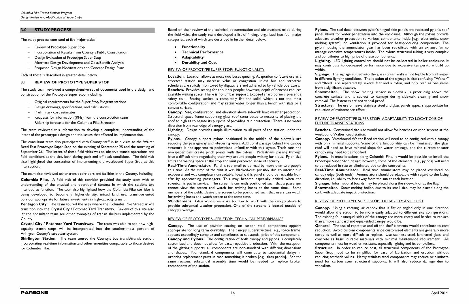
Based on their review of the technical documentation and observations made during the field visits, the study team developed a list of findings organized into four major categories, each of which are described in further detail below:
Functionality Technical Performance Adaptability Durability and Cost
REVIEW OF PROTOTYPE SUPER STOP: FUNCTIONALITY
Location. Location allows at most two buses queuing. Adaptation to future use as a streetcar station may increase vehicular congestion unless bus and streetcar schedules are strictly monitored by dispatchers and adhered to by vehicle operators. Benches. Provides seating for about six people; however, depth of benches reduces available waiting space. There is no lumbar support. Exposed sharp corners present a safety risk. Seating surface is completely flat and solid, which is not the most comfortable configuration, and may retain water longer than a bench with slats or a convex surface. Canopy . Size, configuration, and elevation above sidewalk limit weather protection. Structural space frame supporting glass roof contributes to necessity of placing the roof so high as to negate its purpose of providing rain protection. There is no water diversion from rear edge of canopy glass. Lighting. Design provides ample illumination to all parts of the station under the canopy. Pylons. Canopy support pylons positioned in the middle of the sidewalk are reducing the passageway and obscuring views. Additional passage behind the canopy structure is not apparent to pedestrians unfamiliar with this layout. Trash cans and newspaper bins create pinch points with the pylons. Pedestrians passing through have a difficult time negotiating their way around people waiting for a bus. Pylon size limits the waiting space at the stop and limit perceived sense of security. Real-Time Annunciator. Panel is too small to be read by more than two people at a time. At the time of the visit it was blacked-out, possibly due to intense sun exposure, and was completely unreadable. Ideally, this panel should be readable from afar by approaching passengers. This may become especially critical when the streetcar is put in service. The screen is currently positioned such that a passenger cannot view the screen and watch for arriving buses at the same time. Some members of the public desire the screen to be positioned such that users can watch for arriving buses and watch screen at the same time. Windscreens. Glass windscreens are too low to work with the canopy above to provide substantial weather protection. One of the screens is located outside of canopy coverage. REVIEW OF PROTOTYPE SUPER STOP: TECHNICAL PERFORMANCE
Canopy . The use of powder coating on carbon steel components appears appropriate for long term durability. The canopy superstructure [e.g., space frame] appears exceedingly complex and contributes to substantial price of this component. Canopy and Pylons. The configuration of both canopy and pylons is completely customized and does not allow for easy, repetitive production. With the exception of the glazing supports, all components are non-standard with differing dimensions and shapes. Non-standard components will contribute to substantial delays in ordering replacement parts in case something is broken [e.g., glass panels]. For the same reasons, substantial assembly time would be needed to replace broken components of the station.
Pylons. The seal detail between pylon’s hinged side panels and recessed pylon’s roof panel allows for water penetration into the enclosure. Although the pylons provide adequate weather protection to various components inside [e.g., electronics, snow melting system], no ventilation is provided for heat-producing components. The pylon housing the annunciator gear has been retrofitted with an exhaust fan to manage excessive temperatures inside. The pylons structural tubing is very complex and contributes to high price of these components. Lighting. LED lighting controllers should not be co-located in boiler enclosure. It may contribute to decreased performance due to excessive temperature build up within. Signage. The signage etched into the glass screen walls is not legible from all angles in different lighting conditions. The location of the signage is also confusing: “Walter” and “Reed” are separated by several feet and a pylon, and only read as one name from a significant distance. Snowmelter. The snow melting sensor in sidewalk is protruding above the concrete surface and is subject to damage during sidewalk cleaning and snow removal. The fasteners are not vandal-proof. Structure. The use of heavy stainless steel and glass panels appears appropriate for reduction of maintenance effort. REVIEW OF PROTOTYPE SUPER STOP: ADAPTABILITY TO LOCATIONS OF FUTURE TRANSIT STATIONS
Benches. Constrained site size would not allow for benches or wind screens at the westbound Walter Reed station. Canopy . Westbound Walter Reed station will need to be configured with a canopy with only minimal supports. Some of the functionality can be maintained: the glass roof will need to have minimal slope for water drainage, and the current theater canopy may need to be modified. Pylons. In most locations along Columbia Pike, it would be possible to install the Prototype Super Stop design; however, some of the elements [e.g., pylons] will need to be reduced in size or eliminated due to site constraints. Real-Time Annunciator. Real time annunciators may be placed overhead on canopy edge (both ends). Annunciators should be adaptable with regard to the facing direction, i.e., ability to face away from the sun at each location. Signage. Informational boards may be placed along the sidewalk or at the flag. Snowmelter. Snow melting boiler, due to its small size, may be placed along the curb with adequate impact protection. REVIEW OF PROTOTYPE SUPER STOP: DURABILITY AND COST
Canopy . Using a rectangular canopy that is flat or angled only in one direction would allow the station to be more easily adapted to different site configurations. The existing four unequal sides of the canopy are more costly and harder to replace than a more standard and equal-sided canopy would be. General. The use of repetitive and off-the-shelf elements would contribute to cost reduction. Avoid custom components since customized elements are generally more costly as well as more difficult to replace. Use stainless steel, laminated glass, and concrete as basic, durable materials with minimal maintenance requirement. All components must be weather resistant, especially lighting and its controllers. Structure. In order to reduce cost, all structural components of the Prototype Super Stop need to be simplified for ease of fabrication and erection without reducing aesthetic values. Heavy stainless steel components may reduce or eliminate need for carbon steel structural supports. It will also reduce damage due to vandalism.
Columbia Pike Transit Stations Program Design Review and Modification of Super Stops
Parsons 17 April 2014
3.2 INCORPORATION OF RESULTS FROM COUNTY’S PUBLIC CONSULTATION
The County provided the study team with a copy of the Columbia Pike Super Stops Community Consultation Process Synthesis, a report summarizing the findings from the County’s outreach efforts related to the Prototype Super Stop. As noted in the document, the County’s community consultation consisted of three main components:
1. A survey of stop users, neighbors, and businesses along Columbia Pike 2. A review of emails received prior to survey 3. Two targeted stakeholder feedback sessions
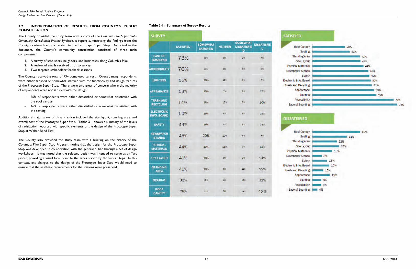
The County received a total of 734 completed surveys. Overall, many respondents were either satisfied or somewhat satisfied with the functionality and design features of the Prototype Super Stop. There were two areas of concern where the majority of respondents were not satisfied with the design:
56% of respondents were either dissatisfied or somewhat dissatisfied with the roof canopy
46% of respondents were either dissatisfied or somewhat dissatisfied with the seating
Additional major areas of dissatisfaction included the site layout, standing area, and overall cost of the Prototype Super Stop. Table 3-1 shows a summary of the levels of satisfaction reported with specific elements of the design of the Prototype Super Stop at Walter Reed East. The County also provided the study team with a briefing on the history of the Columbia Pike Super Stop Program, noting that the design for the Prototype Super Stop was developed in collaboration with the general public through a set of design workshops. It was noted that the selected design was intended to serve as an “art piece”, providing a visual focal point to the areas served by the Super Stops. In this context, any changes to the design of the Prototype Super Stop would need to ensure that the aesthetic requirements for the stations were preserved.
Table 3-1: Summary of Survey Results
Columbia Pike Transit Stations Program Design Review and Modification of Super Stops
Parsons 18 April 2014
3.3 DESIGN EVALUATION OF PROTOTYPE SUPER STOP
Based on review of the Prototype Super Stop and assessment of public feedback, the consultant team led a workshop with County staff on October 9, 2013. The workshop included participation of a broad cross-section of departments within Arlington County to ensure that all aspects of the Prototype Super Stop’s design, construction, operation, maintenance, and functionality were considered while addressing the costs and public response.
As part of the workshop, consultant staff summarized their findings from the County’s community consultation, reviewed their assessment of the Prototype Super Stop, and provided examples of alternative approaches to meeting the requirements of the Transit Station Program. Workshop participants were asked to provide their thoughts on what general issues should be kept in mind as the workshop progressed. Points discussed by the group included:
Off-board fare collection: Stations need to be oriented to future services (bus and streetcar) that use off-board fare collection and allow boarding from multiple points on the platform.
Peaking of ridership: The idea was raised that, if most boardings occur in the eastbound direction and alightings occur in the westbound direction, canopies may not be as critical to alighting passengers who will be leaving the station area. The counterpoint was raised that, as Columbia Pike evolves, it is anticipated that both eastbound and westbound directions are likely to see more balanced levels of boardings.
Seating requirements: o At stations with higher-frequency service, seating may not be as
necessary as lean bars. o It has been observed that people are positioning to be in line for the
next bus, giving up shelter to keep their place in line. o Non-commuters boarding during off-peak hours may have longer wait
times and greater needs for space and seating.
Accessibility: There have been comments from the community that the pylons may affect the accessibility of the station areas. There have also been comments suggesting that the area under the canopy is too small for wheelchair users.
Snowmelting: There was a discussion regarding the need for snow and ice melt equipment in the station area. o It was noted that the community had wanted some level of comfort in
the area of the shelter. o It was also noted that the snowmelting equipment was intended to
prevent icing on platforms, especially on platforms located on hillier portions of Columbia Pike.
o There was a discussion of the energy needs of snowmelting equipment, and it was noted that the team needed to be sensitive to the requirements of the Community Energy Plan.
Station Footprint: Noting that Columbia Pike is evolving, it is important that the stations should sit “lightly on the land,” with a small footprint.
Workshop participants were then split into two smaller groups, each of which was tasked with reviewing the components of the Prototype Super Stop and prioritizing on a scale from 1 (“Essential”) to 5 (“Not required”). The two groups were then merged back together to achieve consensus on how to treat each component in future stations. Table 3-2 summarizes the workshop’s findings regarding each component.
Component Key Findings
Canopy
The canopy is a critical feature of the station design. The team should look at options that would allow for
more cost-effective fabrication and construction. The design should be modified to allow expandability at
the stations.
Signage
Real-time schedule information is a critical requirement at the stations.
Consider shifting from LCD to LED screens to improve visibility.
Consider to adding displays at both ends of the platforms to improve their visibility.
Snowmelt elements
Agreement that there was value to having ice melting equipment to improve safety conditions at the edge of the platform.
Investigate an all-electric system to minimize maintenance needs.
Customization
Any design modifications to the Prototype Super Stop should respect the process used to achieve the current design, especially as the structure currently functions as the art-piece desired by the community.
Stations should serve as focal points—it may not be a bad thing for the stations to stand out from the streetscape around them.
Consider use of standardized forms and materials wherever possible to minimize costs of installation and maintenance.
Seating
Any changes to the Prototype Super Stop design should allow sufficient room under the canopy for seating, recognizing that, at higher-volume and higher- frequency stations, lean bars or less seating may be appropriate.
Fare Collection
The station design should recognize that off-board fare collection is anticipated to become standard in the corridor.
The station design should allow for the future installation of ticket vending machines without impeding accessibility to the station.
The County assumes barrier-free boarding and alighting to both bus and streetcar services.
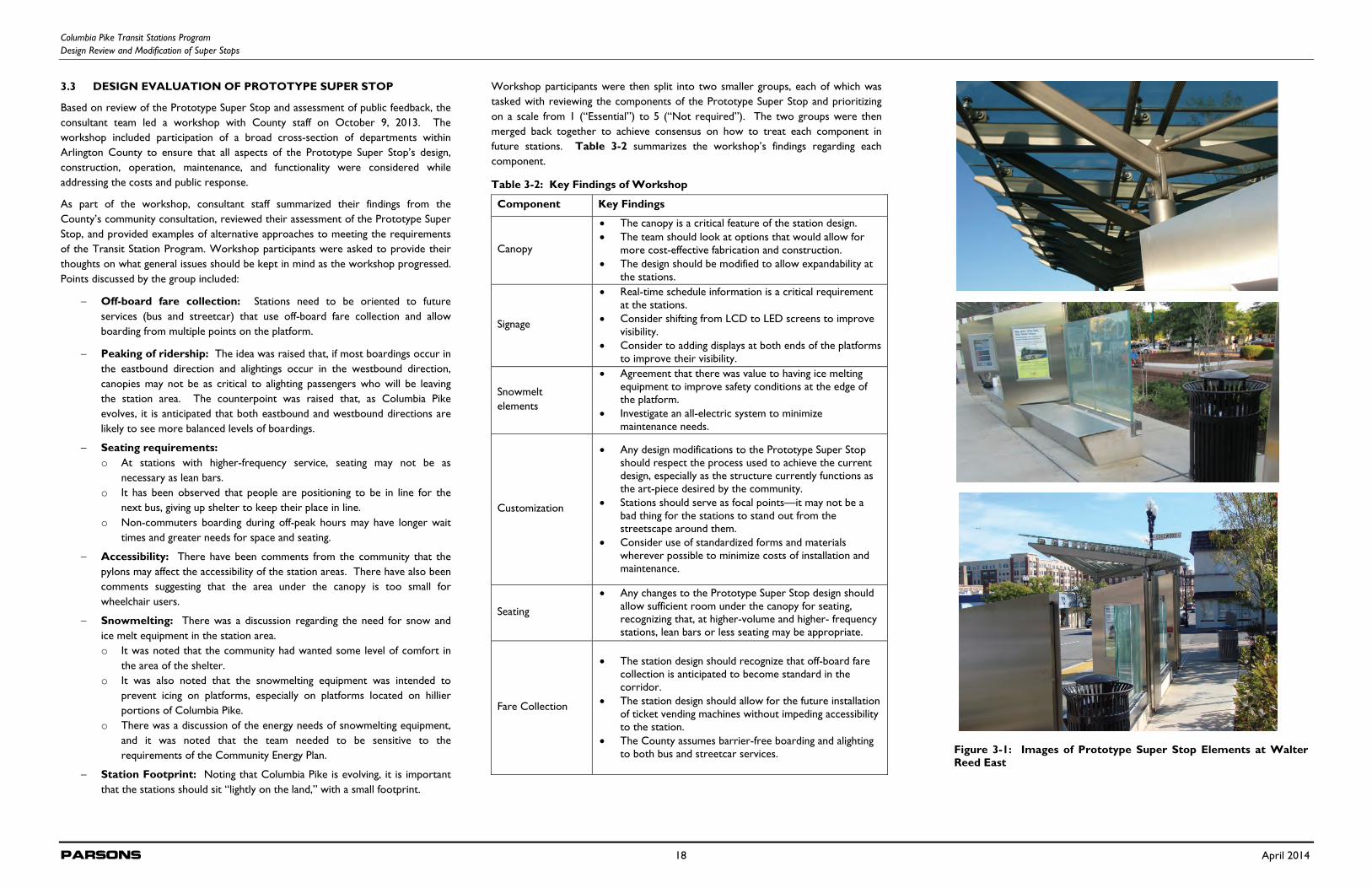
Figure 3-1: Images of Prototype Super Stop Elements at WalterReed East
Table 3-2: Key Findings of Workshop
Columbia Pike Transit Stations Program Design Review and Modification of Super Stops
Parsons 19 April 2014
At the end of the workshop, the consultant team presented four options for how the County could proceed with their approach to the design of the stations. These options and the outcomes whether or not to continue development are presented in Table 3-3. 3.4 ALTERNATIVE DESIGN DEVELOPMENT AND COST/BENEFIT ANALYSIS
Based on the outcomes shown in Table 3-3, the consultant team began development of an “Optimized” Design, as well as a set of new design alternatives for the County’s consideration. The remaining sections of this report provide a detailed account of the development process. 3.5 PROPOSED DESIGN MODIFICATIONS AND CONCEPT DESIGN PLANS
It was anticipated that the final design agreed upon by the County will be advanced to 10-20% design. The design modifications and concept design plans are presented in Section 2 of this report.
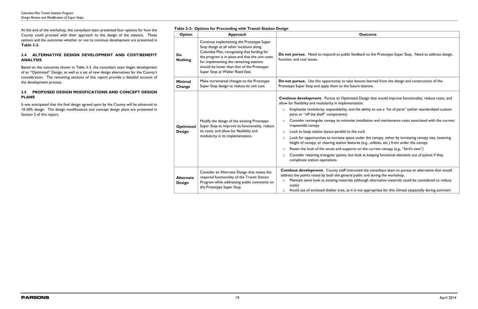
Table 3-3: Options for Proceeding with Transit Station Design Option Approach Outcome
Do Nothing
Continue implementing the Prototype Super Stop design at all other locations along Columbia Pike, recognizing that funding for the program is in place and that the unit costs for implementing the remaining stations should be lower than that of the Prototype Super Stop at Walter Reed East.
Do not pursue. Need to respond to public feedback to the Prototype Super Stop. Need to address design, function, and cost issues.
Minimal Change
Make incremental changes to the Prototype Super Stop design to reduce its unit cost.
Do not pursue. Use this opportunity to take lessons learned from the design and construction of the Prototype Super Stop and apply them to the future stations.
Optimized Design
Modify the design of the existing Prototype Super Stop to improve its functionality, reduce its costs, and allow for flexibility and modularity in its implementation.
Continue development. Pursue an Optimized Design that would improve functionality, reduce costs, and allow for flexibility and modularity in implementation.
o Emphasize modularity, expandability, and the ability to use a “kit of parts” (either standardized custom parts or “off the shelf” components)
o Consider rectangular canopy to minimize installation and maintenance costs associated with the current trapezoidal canopy
o Look to keep station layout parallel to the curb
o Look for opportunities to increase space under the canopy, either by increasing canopy size, lowering height of canopy, or clearing station features (e.g., utilities, etc.) from under the canopy
o Retain the look of the struts and supports on the current canopy (e.g., “bird’s nest”)
o Consider retaining triangular pylons, but look at keeping functional elements out of pylons if they complicate station operations
Alternate Design
Consider an Alternate Design that meets the required functionality of the Transit Station Program while addressing public comments on the Prototype Super Stop.
Continue development. County staff instructed the consultant team to pursue an alternative that would address the points raised by both the general public and during the workshop. o Maintain same look as existing materials (although alternative materials could be considered to reduce
costs) o Avoid use of enclosed shelter area, as it is not appropriate for this climate (especially during summer)
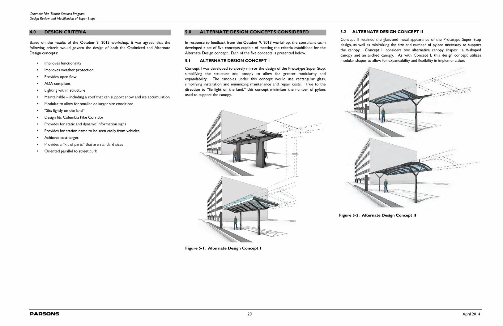
Columbia Pike Transit Stations Program Design Review and Modification of Super Stops
Parsons 20 April 2014
4.0 DESIGN CRITERIA
Based on the results of the October 9, 2013 workshop, it was agreed that the following criteria would govern the design of both the Optimized and Alternate Design concepts:
• Improves functionality
• Improves weather protection
• Provides open flow
• ADA compliant
• Lighting within structure
• Maintainable – including a roof that can support snow and ice accumulation
• Modular to allow for smaller or larger site conditions
• “Sits lightly on the land”
• Design fits Columbia Pike Corridor
• Provides for static and dynamic information signs
• Provides for station name to be seen easily from vehicles
• Achieves cost target
• Provides a “kit of parts” that are standard sizes
• Oriented parallel to street curb
5.0 ALTERNATE DESIGN CONCEPTS CONSIDERED
In response to feedback from the October 9, 2013 workshop, the consultant team developed a set of five concepts capable of meeting the criteria established for the Alternate Design concept. Each of the five concepts is presented below.
5.1 ALTERNATE DESIGN CONCEPT 1
Concept I was developed to closely mirror the design of the Prototype Super Stop, simplifying the structure and canopy to allow for greater modularity and expandability. The canopies under this concept would use rectangular glass, simplifying installation and minimizing maintenance and repair costs. True to the direction to “lie light on the land,” this concept minimizes the number of pylons used to support the canopy.
5.2 ALTERNATE DESIGN CONCEPT II
Concept II retained the glass-and-metal appearance of the Prototype Super Stop design, as well as minimizing the size and number of pylons necessary to support the canopy. Concept II considers two alternative canopy shapes: a V-shaped canopy and an arched canopy. As with Concept I, this design concept utilizes modular shapes to allow for expandability and flexibility in implementation.
Figure 5-1: Alternate Design Concept 1
Figure 5-2: Alternate Design Concept II
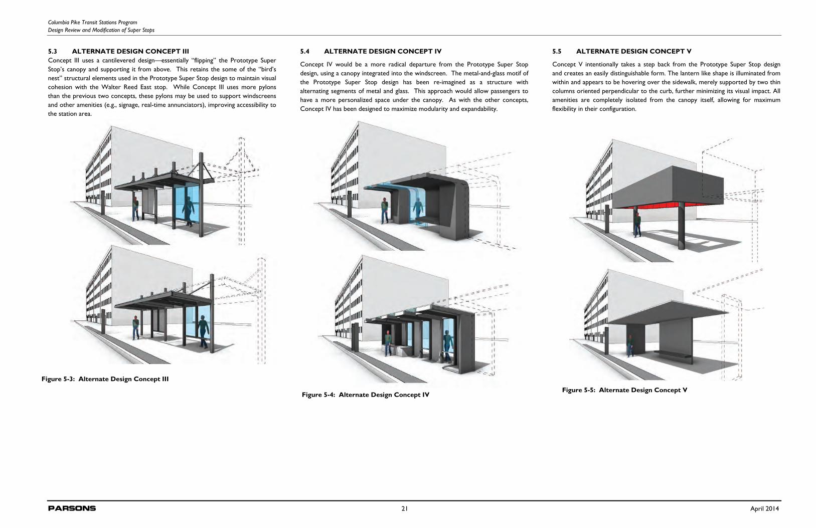
Columbia Pike Transit Stations Program Design Review and Modification of Super Stops
Parsons 21 April 2014
5.3 ALTERNATE DESIGN CONCEPT III Concept III uses a cantilevered design—essentially “flipping” the Prototype Super Stop’s canopy and supporting it from above. This retains the some of the “bird’s nest” structural elements used in the Prototype Super Stop design to maintain visual cohesion with the Walter Reed East stop. While Concept III uses more pylons than the previous two concepts, these pylons may be used to support windscreens and other amenities (e.g., signage, real-time annunciators), improving accessibility to the station area.
5.4 ALTERNATE DESIGN CONCEPT IV
Concept IV would be a more radical departure from the Prototype Super Stop design, using a canopy integrated into the windscreen. The metal-and-glass motif of the Prototype Super Stop design has been re-imagined as a structure with alternating segments of metal and glass. This approach would allow passengers to have a more personalized space under the canopy. As with the other concepts, Concept IV has been designed to maximize modularity and expandability.
5.5 ALTERNATE DESIGN CONCEPT V
Concept V intentionally takes a step back from the Prototype Super Stop design and creates an easily distinguishable form. The lantern like shape is illuminated from within and appears to be hovering over the sidewalk, merely supported by two thin columns oriented perpendicular to the curb, further minimizing its visual impact. All amenities are completely isolated from the canopy itself, allowing for maximum flexibility in their configuration.
Figure 5-3: Alternate Design Concept III
Figure 5-4: Alternate Design Concept IV Figure 5-5: Alternate Design Concept V
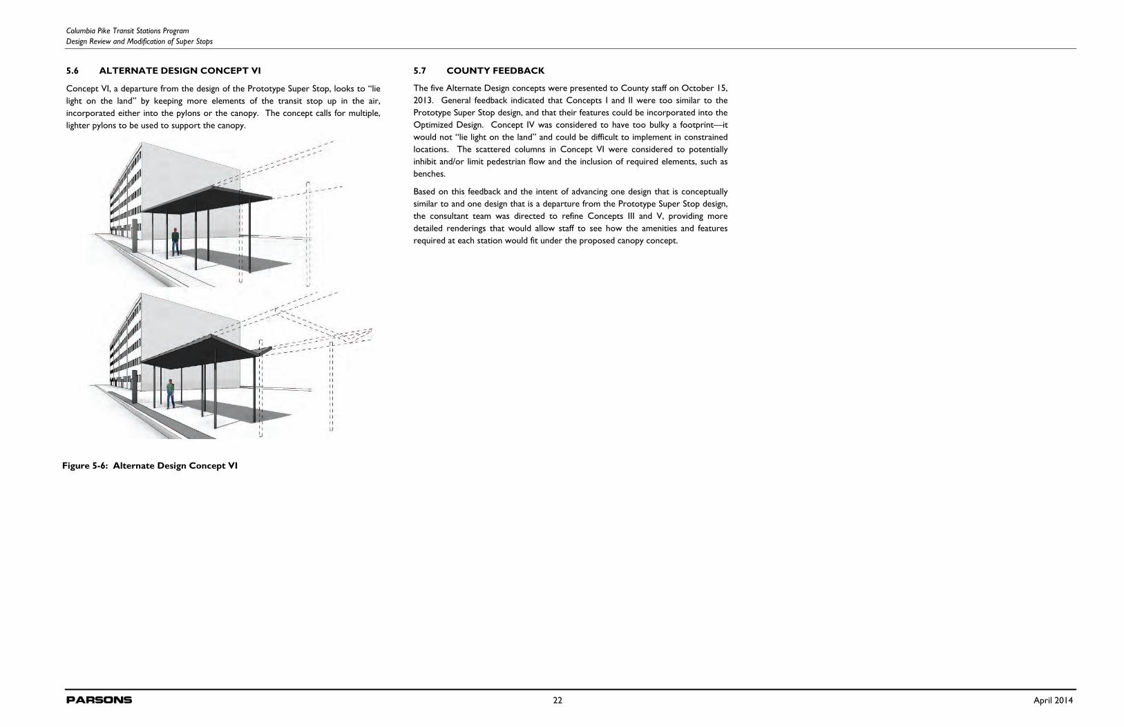
Columbia Pike Transit Stations Program Design Review and Modification of Super Stops
Parsons 22 April 2014
5.6 ALTERNATE DESIGN CONCEPT VI
Concept VI, a departure from the design of the Prototype Super Stop, looks to “lie light on the land” by keeping more elements of the transit stop up in the air, incorporated either into the pylons or the canopy. The concept calls for multiple, lighter pylons to be used to support the canopy.
5.7 COUNTY FEEDBACK
The five Alternate Design concepts were presented to County staff on October 15, 2013. General feedback indicated that Concepts I and II were too similar to the Prototype Super Stop design, and that their features could be incorporated into the Optimized Design. Concept IV was considered to have too bulky a footprint—it would not “lie light on the land” and could be difficult to implement in constrained locations. The scattered columns in Concept VI were considered to potentially inhibit and/or limit pedestrian flow and the inclusion of required elements, such as benches.
Based on this feedback and the intent of advancing one design that is conceptually similar to and one design that is a departure from the Prototype Super Stop design, the consultant team was directed to refine Concepts III and V, providing more detailed renderings that would allow staff to see how the amenities and features required at each station would fit under the proposed canopy concept.
Figure 5-6: Alternate Design Concept VI
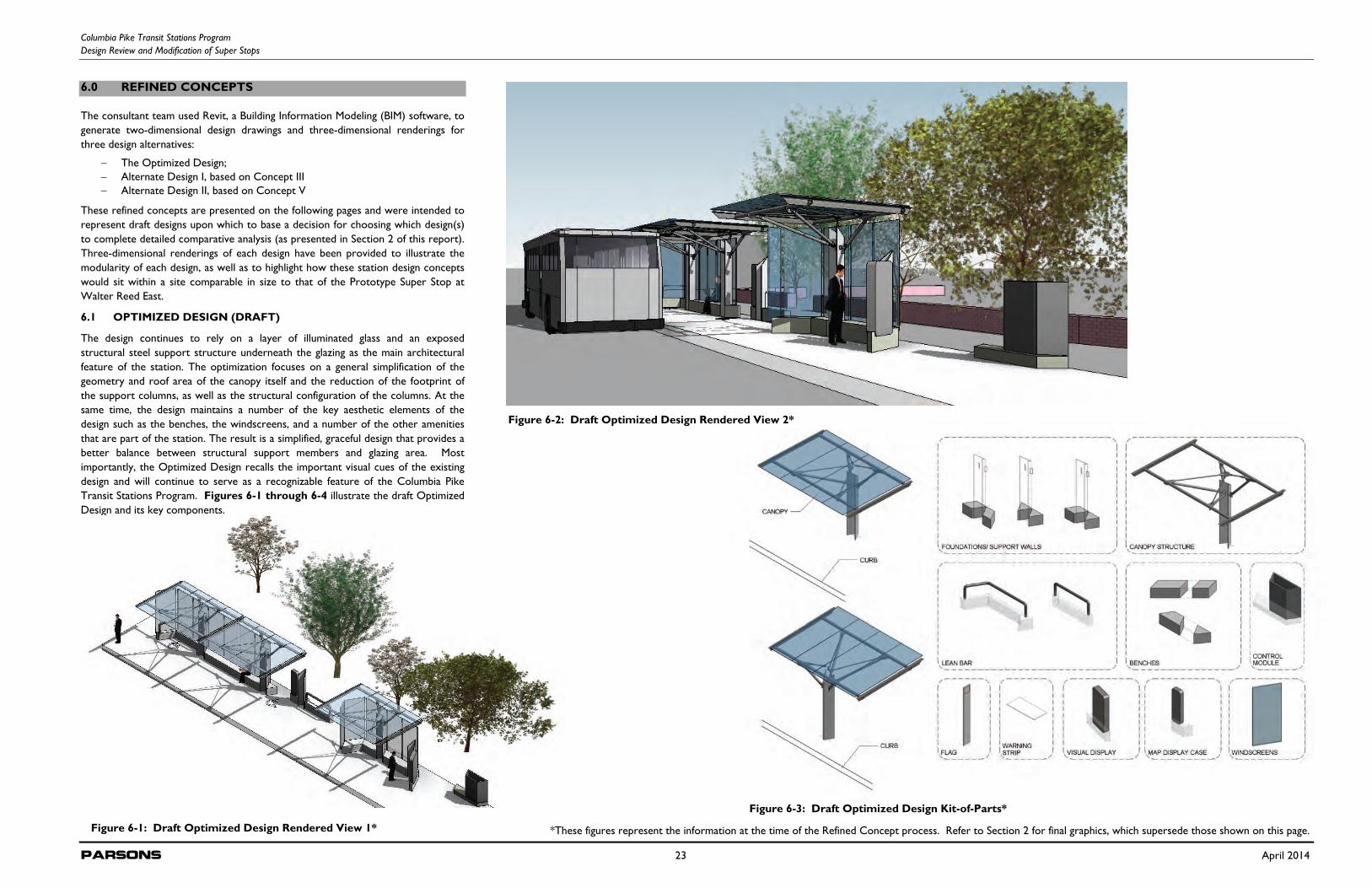
Columbia Pike Transit Stations Program Design Review and Modification of Super Stops
Parsons 23 April 2014
6.0 REFINED CONCEPTS
The consultant team used Revit, a Building Information Modeling (BIM) software, to generate two-dimensional design drawings and three-dimensional renderings for three design alternatives:
The Optimized Design; Alternate Design I, based on Concept III Alternate Design II, based on Concept V
These refined concepts are presented on the following pages and were intended to represent draft designs upon which to base a decision for choosing which design(s) to complete detailed comparative analysis (as presented in Section 2 of this report). Three-dimensional renderings of each design have been provided to illustrate the modularity of each design, as well as to highlight how these station design concepts would sit within a site comparable in size to that of the Prototype Super Stop at Walter Reed East.
6.1 OPTIMIZED DESIGN (DRAFT)
The design continues to rely on a layer of illuminated glass and an exposed structural steel support structure underneath the glazing as the main architectural feature of the station. The optimization focuses on a general simplification of the geometry and roof area of the canopy itself and the reduction of the footprint of the support columns, as well as the structural configuration of the columns. At the same time, the design maintains a number of the key aesthetic elements of the design such as the benches, the windscreens, and a number of the other amenities that are part of the station. The result is a simplified, graceful design that provides a better balance between structural support members and glazing area. Most importantly, the Optimized Design recalls the important visual cues of the existing design and will continue to serve as a recognizable feature of the Columbia Pike Transit Stations Program. Figures 6-1 through 6-4 illustrate the draft Optimized Design and its key components.
Figure 6-1: Draft Optimized Design Rendered View 1*
Figure 6-2: Draft Optimized Design Rendered View 2*
Figure 6-3: Draft Optimized Design Kit-of-Parts*
*These figures represent the information at the time of the Refined Concept process. Refer to Section 2 for final graphics, which supersede those shown on this page.
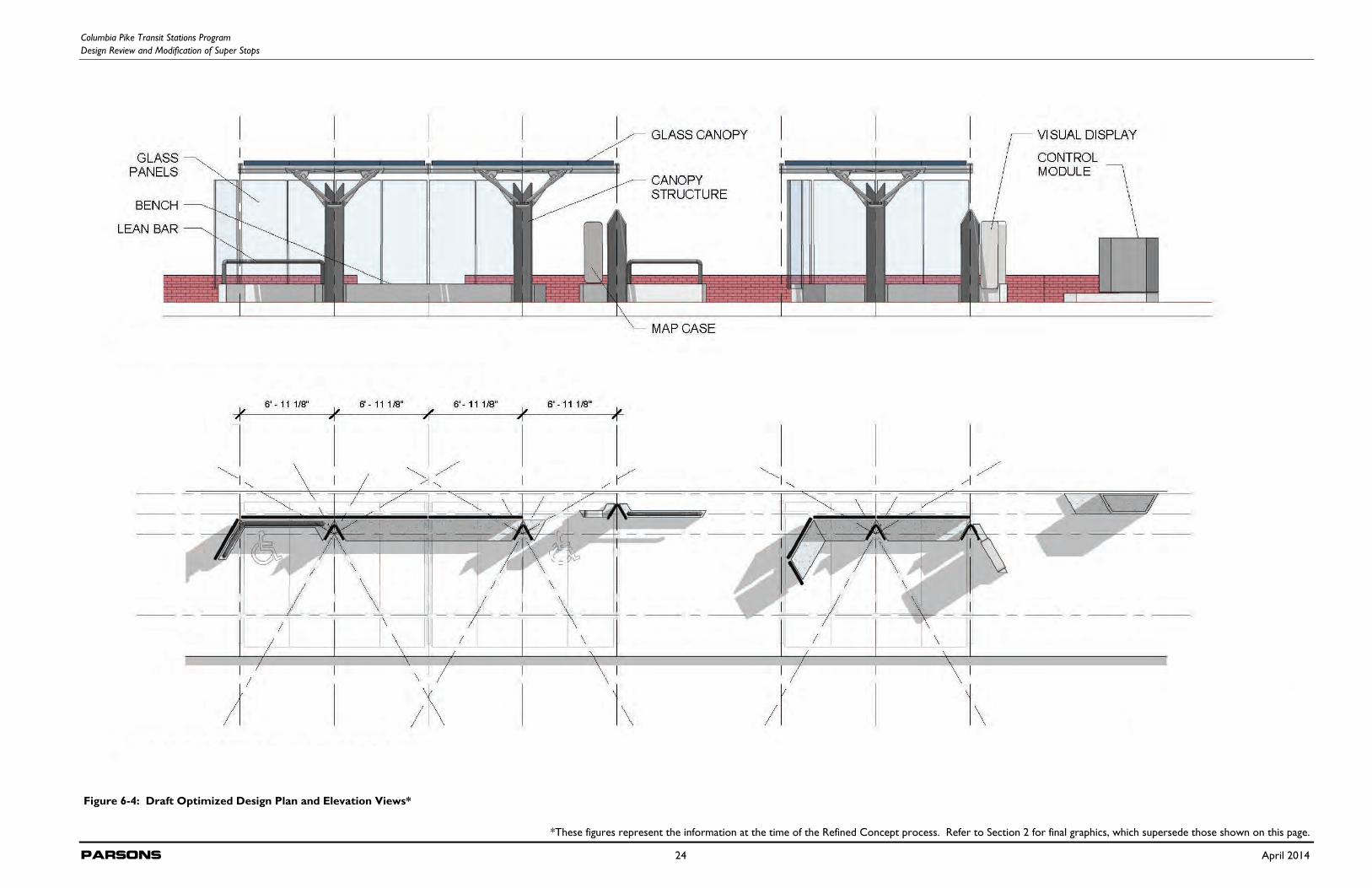
Columbia Pike Transit Stations Program Design Review and Modification of Super Stops
Parsons 24 April 2014
Figure 6-4: Draft Optimized Design Plan and Elevation Views*
*These figures represent the information at the time of the Refined Concept process. Refer to Section 2 for final graphics, which supersede those shown on this page.
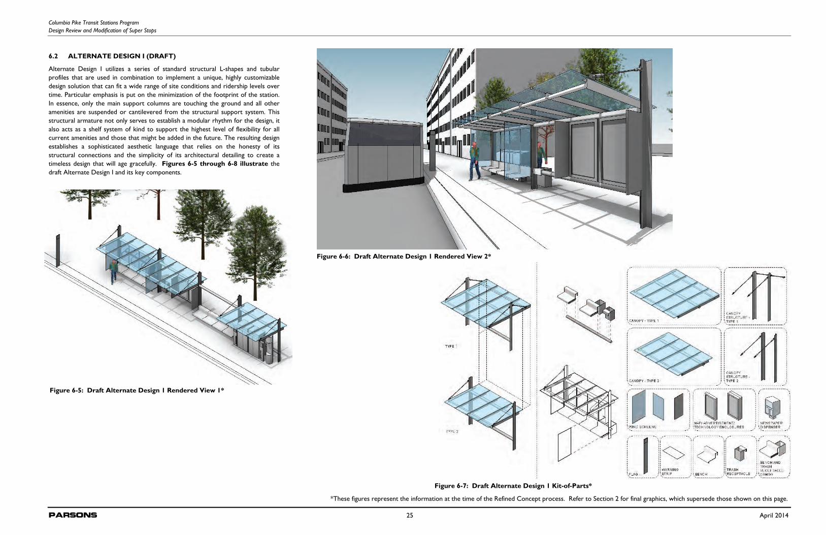
Columbia Pike Transit Stations Program Design Review and Modification of Super Stops
Parsons 25 April 2014
6.2 ALTERNATE DESIGN I (DRAFT)
Alternate Design I utilizes a series of standard structural L-shapes and tubular profiles that are used in combination to implement a unique, highly customizable design solution that can fit a wide range of site conditions and ridership levels over time. Particular emphasis is put on the minimization of the footprint of the station. In essence, only the main support columns are touching the ground and all other amenities are suspended or cantilevered from the structural support system. This structural armature not only serves to establish a modular rhythm for the design, it also acts as a shelf system of kind to support the highest level of flexibility for all current amenities and those that might be added in the future. The resulting design establishes a sophisticated aesthetic language that relies on the honesty of its structural connections and the simplicity of its architectural detailing to create a timeless design that will age gracefully. Figures 6-5 through 6-8 illustrate the draft Alternate Design I and its key components.
Figure 6-5: Draft Alternate Design 1 Rendered View 1*
Figure 6-6: Draft Alternate Design 1 Rendered View 2*
Figure 6-7: Draft Alternate Design 1 Kit-of-Parts*
*These figures represent the information at the time of the Refined Concept process. Refer to Section 2 for final graphics, which supersede those shown on this page.
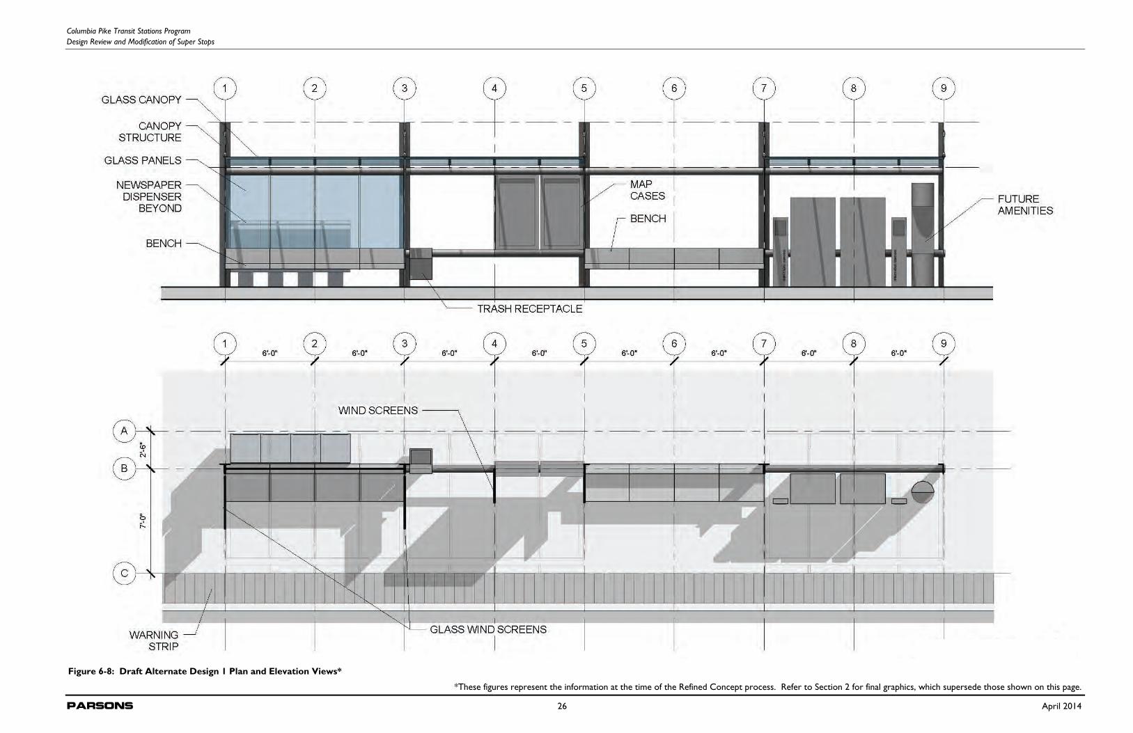
Columbia Pike Transit Stations Program Design Review and Modification of Super Stops
Parsons 26 April 2014
Figure 6-8: Draft Alternate Design 1 Plan and Elevation Views* *These figures represent the information at the time of the Refined Concept process. Refer to Section 2 for final graphics, which supersede those shown on this page.
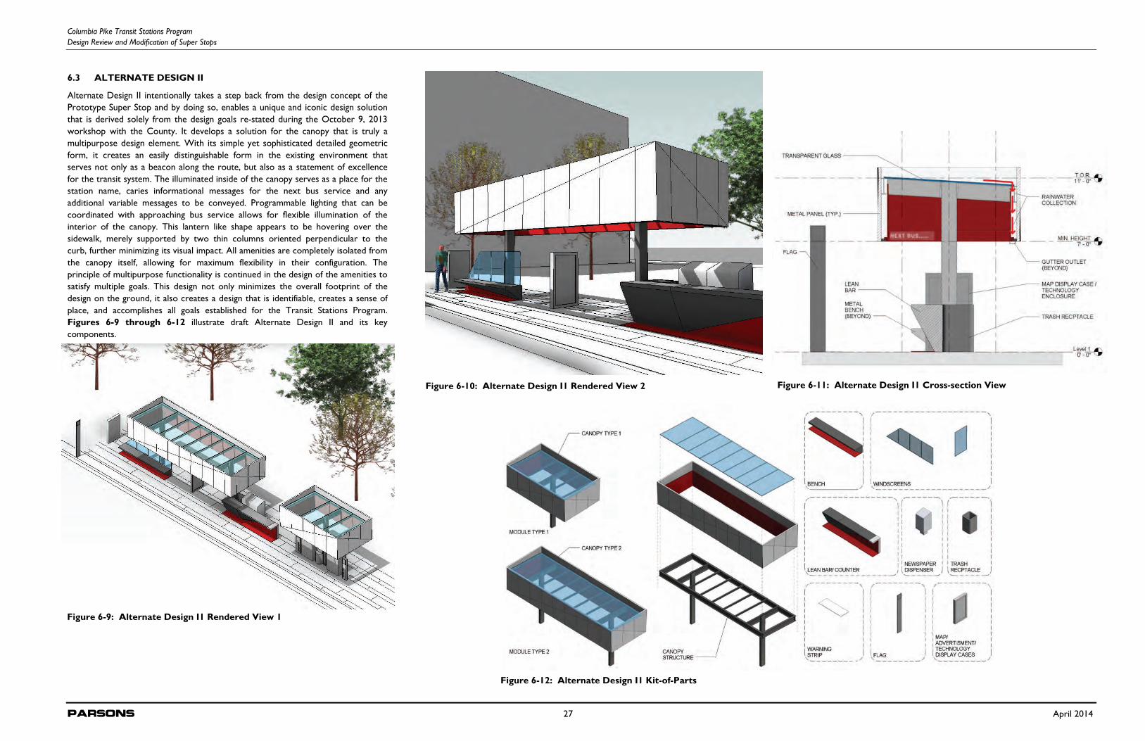
Columbia Pike Transit Stations Program Design Review and Modification of Super Stops
Parsons 27 April 2014
6.3 ALTERNATE DESIGN II
Alternate Design II intentionally takes a step back from the design concept of the Prototype Super Stop and by doing so, enables a unique and iconic design solution that is derived solely from the design goals re-stated during the October 9, 2013 workshop with the County. It develops a solution for the canopy that is truly a multipurpose design element. With its simple yet sophisticated detailed geometric form, it creates an easily distinguishable form in the existing environment that serves not only as a beacon along the route, but also as a statement of excellence for the transit system. The illuminated inside of the canopy serves as a place for the station name, caries informational messages for the next bus service and any additional variable messages to be conveyed. Programmable lighting that can be coordinated with approaching bus service allows for flexible illumination of the interior of the canopy. This lantern like shape appears to be hovering over the sidewalk, merely supported by two thin columns oriented perpendicular to the curb, further minimizing its visual impact. All amenities are completely isolated from the canopy itself, allowing for maximum flexibility in their configuration. The principle of multipurpose functionality is continued in the design of the amenities to satisfy multiple goals. This design not only minimizes the overall footprint of the design on the ground, it also creates a design that is identifiable, creates a sense of place, and accomplishes all goals established for the Transit Stations Program. Figures 6-9 through 6-12 illustrate draft Alternate Design II and its key components.
Figure 6-9: Alternate Design I1 Rendered View 1
Figure 6-10: Alternate Design I1 Rendered View 2
Figure 6-12: Alternate Design I1 Kit-of-Parts
Figure 6-11: Alternate Design I1 Cross-section View
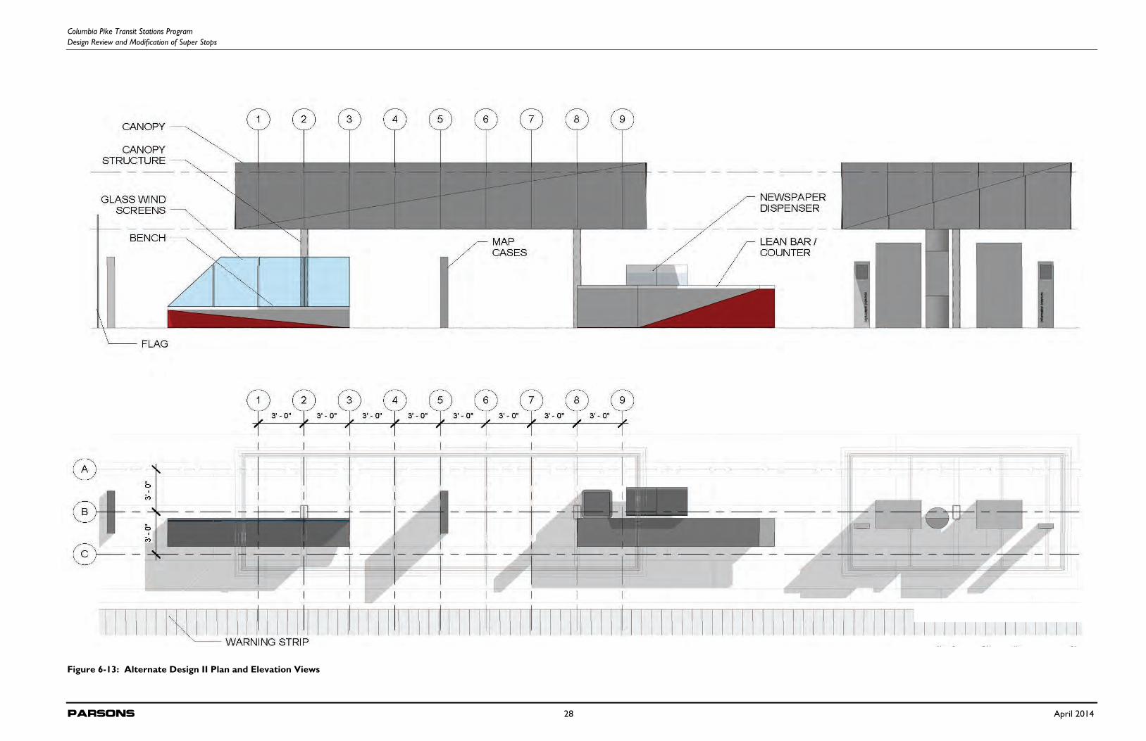
Columbia Pike Transit Stations Program Design Review and Modification of Super Stops
Parsons 28 April 2014
Figure 6-13: Alternate Design II Plan and Elevation Views
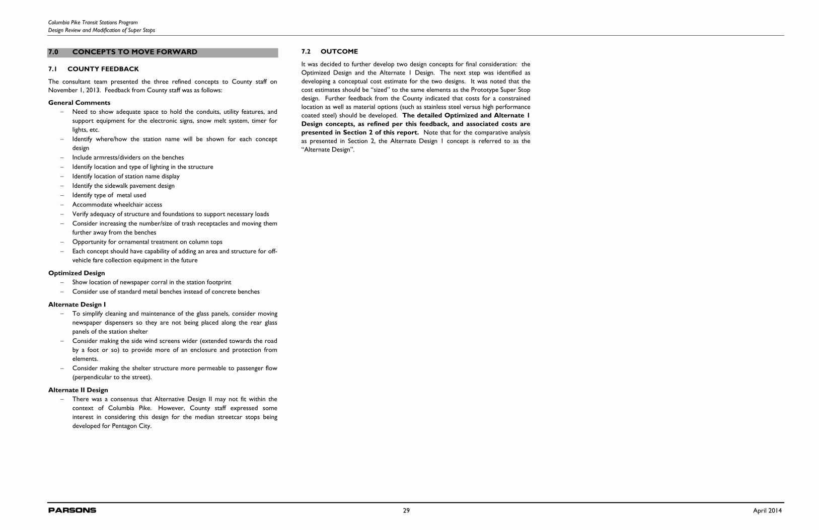
Columbia Pike Transit Stations Program Design Review and Modification of Super Stops
Parsons 29 April 2014
7.0 CONCEPTS TO MOVE FORWARD
7.1 COUNTY FEEDBACK
The consultant team presented the three refined concepts to County staff on November 1, 2013. Feedback from County staff was as follows:
General Comments Need to show adequate space to hold the conduits, utility features, and
support equipment for the electronic signs, snow melt system, timer for lights, etc.
Identify where/how the station name will be shown for each concept design
Include armrests/dividers on the benches Identify location and type of lighting in the structure Identify location of station name display Identify the sidewalk pavement design Identify type of metal used Accommodate wheelchair access Verify adequacy of structure and foundations to support necessary loads Consider increasing the number/size of trash receptacles and moving them
further away from the benches Opportunity for ornamental treatment on column tops Each concept should have capability of adding an area and structure for off-
vehicle fare collection equipment in the future
Optimized Design Show location of newspaper corral in the station footprint Consider use of standard metal benches instead of concrete benches
Alternate Design I To simplify cleaning and maintenance of the glass panels, consider moving
newspaper dispensers so they are not being placed along the rear glass panels of the station shelter
Consider making the side wind screens wider (extended towards the road by a foot or so) to provide more of an enclosure and protection from elements.
Consider making the shelter structure more permeable to passenger flow (perpendicular to the street).
Alternate II Design There was a consensus that Alternative Design II may not fit within the
context of Columbia Pike. However, County staff expressed some interest in considering this design for the median streetcar stops being developed for Pentagon City.
7.2 OUTCOME
It was decided to further develop two design concepts for final consideration: the Optimized Design and the Alternate 1 Design. The next step was identified as developing a conceptual cost estimate for the two designs. It was noted that the cost estimates should be “sized” to the same elements as the Prototype Super Stop design. Further feedback from the County indicated that costs for a constrained location as well as material options (such as stainless steel versus high performance coated steel) should be developed. The detailed Optimized and Alternate 1 Design concepts, as refined per this feedback, and associated costs are presented in Section 2 of this report. Note that for the comparative analysis as presented in Section 2, the Alternate Design 1 concept is referred to as the “Alternate Design”.