Embed Size (px)
Citation preview

APPENDIX B:
DRAFT ENGINEER’S DESIGN
REPORT


Saint Mary’s Airport (KSM) Airport Improvements Project DOT&PF No. Z605630000
Draft Engineer’s Design Report
Prepared by:
DOWL
3535 College Road, Suite 100
Fairbanks, AK 99709
907-374-0275
www.dowl.com
August 2021

INTENTIONALLY LEFT BLANK

Draft Engineer’s Design Report
Saint Mary’s Airport (KSM)
Airport Improvements Project
DOT&PF No. Z605630000
Prepared for:
State of Alaska
Department of Transportation and Public Facilities Northern Region Design & Construction - Aviation
Prepared by:
DOWL 3535 College Road, Suite 100
Fairbanks, AK 99709
August 2021

Airport Improvements Project
St. Mary’s Airport (KSM) ii August 2021
TABLE OF CONTENTS
1.0 INTRODUCTION ............................................................................................... 1-1
1.1 Foreword .............................................................................................................1-1
1.2 Scope of Work .....................................................................................................1-1
1.3 PIH Draft EDR Objectives ...................................................................................1-2
2.0 DESIGN ANALYSIS .......................................................................................... 2-1
2.1 Airport Layout Considerations .............................................................................2-1
2.2 Soils & Grading ...................................................................................................2-2
Historic Project and Subsurface Data Overview ..................................................2-2
Required Soils .....................................................................................................2-3
Uncertainties .......................................................................................................2-3
Available Aggregates ..........................................................................................2-4
Internal Drainage & Frost Depth ..........................................................................2-4
2.3 Drainage .............................................................................................................2-4
2.4 Pavement Design ................................................................................................2-4
Frost Design ........................................................................................................2-6
Fleet Mix .............................................................................................................2-6
Subgrade Conditions & CBR ...............................................................................2-6
Proposed Pavement Sections .............................................................................2-6
2.5 Signage ...............................................................................................................2-8
2.6 Lighting ...............................................................................................................2-8
2.7 Navigational Aids (Navaids) ................................................................................2-9
2.8 Material Source Analysis .....................................................................................2-9
Crushed Aggregate Surface Course (P-299) .......................................................2-9
Subbase Course, 1” Minus (P-154) ................................................................... 2-10
Subbase Course, 3” Minus (Embankment/P-154) ............................................. 2-10
Asphalt Aggregate (P-401) ................................................................................ 2-10
Crushed Surfacing Base Course (P-209) .......................................................... 2-10
2.9 Barge Haul Analysis .......................................................................................... 2-10
2.10 Barge Landings ................................................................................................. 2-11
2.11 Haul Route Analysis .......................................................................................... 2-11
2.12 Conceptual Project Phasing .............................................................................. 2-12
3.0 MODIFICATIONS TO AGENCY STANDARDS ................................................ 3-1
3.1 Modifications to DOT&PF Design Standards .......................................................3-1
3.2 Modifications to FAA Design Standards ..............................................................3-1
3.3 Modifications to DOT&PF Construction Standards ..............................................3-1
4.0 COST ESTIMATE ............................................................................................. 4-1
4.1 Engineer’s Estimate ............................................................................................4-1
5.0 PROJECT SCHEDULE ..................................................................................... 5-1
5.1 Time Constraints .................................................................................................5-1
5.2 Recommended Schedule ....................................................................................5-1
TABLES
Table 2-1 – Summary of Runway 17/35 Design Dimensions ....................................................2-1
Table 2-2 – Summary of Runway 6/24 Design Dimensions ......................................................2-1
Table 2-3 – Summary of Taxiways A & B Design Dimensions ..................................................2-2

Airport Improvements Project
St. Mary’s Airport (KSM) iii August 2021
Table 2-4 – Design Aircraft Fleet Mix .......................................................................................2-6
Table 2-5 – Asphalt Apron Pavement Section ..........................................................................2-7
Table 2-6 – Unpaved Heavy Aircraft Section ............................................................................2-7
Table 2-7 – Heavy Aircraft Shoulder Section ............................................................................2-8
Table 2-8 – Unpaved Light Aircraft Section ..............................................................................2-8
Table 2-9 –Light Aircraft Shoulder Section ...............................................................................2-8
Table 2-10 – Runway 17/35 Half-Width Operation Dimensions .............................................. 2-12
Table 4-1 – Preliminary Baseline Construction Estimate ..........................................................4-1
APPENDICES
Appendix A: Drainage Calculations
Appendix B: AASHTOWARE (AWP) PIH Estimate

Airport Improvements Project
St. Mary’s Airport (KSM) iv August 2021
LIST OF ACRONYMS AC .............................................................................................................. FAA Advisory Circular AOA ......................................................................................................... Airport Operations Area ALP ................................................................................................................. Airport Layout Plan ARC ......................................................................................................... Airport Reference Code CABC ........................................................................................ Crushed Aggregate Base Course CASC ....................................................................................Crushed Aggregate Surface Course CSPP .................................................................................... Construction Safety & Phasing Plan DOT&PF ................................................ Alaska Department of Transportation & Public Facilities EEB ................................................................................................ Electrical Equipment Building FAA .............................................................................................. Federal Aviation Administration FAR .................................................................................................Federal Aviation Regulations GS ............................................................................................................................... Glideslope ICAP .................................................................................................Indirect Cost Allocation Plan ILS ..................................................................................................... Instrument Landing System KSM or PASM ................................................................................................ Saint Mary’s Airport LOC ............................................................................................................................... Localizer M&O ............................................................................................... Maintenance and Operations MIRL ................................................................................. Medium Intensity Runway Edge Lights MALSR ..... Medium Intensity Approach Lighting System with Runway Alignment Indicator Lights NAVAID .............................................................................................................. Navigational Aid OFA ................................................................................................................... Object Free Area PAPI ....................................................................................... Precision Approach Path Indicator REIL ................................................................................................. Runway End Identifier Lights RPZ ....................................................................................................... Runway Protection Zone RSA ............................................................................................................. Runway Safety Area RWY ................................................................................................................................ Runway TDG .......................................................................................................... Taxiway Design Group TOFA ............................................................................................. Taxiway Object Freeway Area TSA .............................................................................................................. Taxiway Safety Area TWY ................................................................................................................................. Taxiway TL ................................................................................................................................... Taxilane VASI .......................................................................................... Visual Approach Slope Indicator
Notice to Users This report reflects the current state of design and reflects design decisions made at the time of publication. Changes frequently occur during the design process that may significantly affect final design. Persons who may rely on information contained in this document should check with DOT&PF for the current design. Contact the Project Manager, Christopher Johnston, at 907-451-2322 or [email protected] for this information.

SECTION 1
St. Mary’s Airport (KSM)
Airport Improvements Project 1-1 August 2021
1.0 INTRODUCTION
1.1 Foreword
Saint Mary’s Airport (KSM) is located approximately seven road miles west of the community of Saint Mary’s, which lies on the north bank of the Andreafsky River five miles from the confluence with the Yukon River. Saint Mary’s is located 450 air miles west-northwest of Anchorage and 515 air miles southwest of Fairbanks. The community is served by barge and air transport. The Saint Mary’s barge landing on the Andreafsky River provides the only deep-water dock in the Yukon Delta. A 22-mile local gravel road links the village of Saint Mary’s to the villages of Andreafsky, Pitka’s Point, and Mountain Village. This road is not maintained during winter months.
KSM has two runways: Runway 17/35 is a gravel runway measuring 6,000-feet by 150-feet, and Runway 6/24 is a gravel runway measuring 1,520-feet by 60-feet. Gravel taxiways (Taxiways A and B) connect Runway 17/35 to the 250-foot by 1,360-foot main apron. The southern half of the main apron is paved (150,000 SF) and the remainder of the apron is surfaced with gravel. Taxiway A also connects Runway 17/35 to the 295-foot by 345-foot gravel General Aviation (GA) Apron (DOT&PF 2020).
1.2 Scope of Work
The Alaska Department of Transportation and Public Facilities (DOT&PF) in cooperation with the Federal Aviation Administration (FAA) proposes to upgrade existing facilities at KSM. Work will include the following: DOWL Design Elements:
• Resurfacing of unpaved Runway 17/35 and extending the Runway Safety Area (RSA) north approximately 450 feet.
• Resurfacing of unpaved Runway 6/24 and widening of existing RSA embankment by approximately 35 feet.
• Resurfacing unpaved Taxiways A and B
• Resurfacing the transient apron and the unpaved portion of the main apron
• Repaving the main asphalt apron
• Addressing drainage issues within the embankment and structural sections throughout.
• Drainage improvements, including new conveyance ditches and culvert replacement
• Demolition of existing FAA-owned Navigational Aids, including Runway 17 Medium Intensity Approach Lighting System with Runway Alignment Indicator Lights (MALSR) and existing Visual Approach Slope Indicators (VASI).
• Demolition of existing lighting equipment.
• Layout of new lighted signs. FAA Navigational Aid Design Elements
The FAA will complete design of new FAA Navigational Aids via a Reimbursable Agreement between FAA and DOT&PF. FAA Design elements include:
• New Precision Approach Path Indicators (PAPI) for each end of Runway 17/35
• New Runway End Identifier Lights (REIL) at the Runway 17 threshold and the Runway 35 displaced threshold.

SECTION 1
St. Mary’s Airport (KSM)
Airport Improvements Project 1-2 August 2021
Electrical Design Elements
New electrical design will be completed under a separate contract. Electrical design components include the following:
• Replacement of all existing runway edge lighting with new Medium Intensity Runway Edge Lighting (MIRL) systems, including new lighting regulators.
• Replacement of existing Medium Intensity Taxiway Edge Lighting (MITL) on Taxiways A and B, and west apron, including new regulators.
• Design of new power service to new lighted airfield signs on provided layout.
• Replacement of the primary wind cone and foundation.
• Replacement of the segmented circle.
• Replacement of the supplementary wind cone and foundation.
• Replacement of the Electrical Equipment Building and backup generator.
• Replacement of the airport beacon.
The DOT&PF anticipates that construction of this project will begin in 2022 and is expected to last two construction seasons.
1.3 Draft Engineer’s Design Report (EDR) Objectives
This draft EDR is intended to provide a narrative of the design process; it describes the technical aspects of the project design, including a review of existing conditions, statement of design criteria and assumptions, modifications to DOT&PF standards, phasing elements, and preliminary quantity and cost estimates. Note that since the geotechnical investigation at the project site is still pending, substantial design changes to materials and typical sections that would not normally occur after this point in the design process may be necessary.
Section 2, Design Analysis, generally follows the DOT&PF Alaska Aviation Preconstruction Manual, Attachment E Engineer’s Design Report Outline.

SECTION 2
St. Mary’s Airport (KSM)
Airport Improvements Project 2-1 August 2021
2.0 DESIGN ANALYSIS
2.1 Airport Layout Considerations
Dimensions, grades, horizontal, and vertical layout will conform to the current FAA Advisory Circular (AC) 150/5300-13A, Change 1, Airport Design. Airport dimensions will generally follow the near-term layout provided in the recent Airport Layout Plan (ALP) update, with exceptions as noted in the tables below. Runway 17/35 will be designed to Airport Design Group (ADG) B-III, including extending the RSA embankment north of Runway 17 and displacing the runway 35 threshold north to provide the standard 600’ RSA prior to each runway threshold. Runway 17/35 design dimensions are shown in Table 2-1 below.
Table 2-1 – Summary of Runway 17/35 Design Dimensions
Dimension Existing ADG B-III Standard Design
Runway Length 6,000’ - 6,000’
Runway Width 150’ 100’1 150’
Runway Shoulder Width 20’ 20’ 20’
RSA Width 300’ 300’ 300’
RSA Length beyond Runway Threshold (Runway 17 / Runway 35 end)
195’/185’ 600’/600’ 600’/600’
Runway Object Free Area (OFA) Width 800’ 800’ 800’
Runway OFA Length Beyond Runway Threshold 1000’ 600’ 600’ 1Existing 150’ runway width will be maintained to support critical Lockheed C-130 (FAA Design Group C-IV) revenue operations without special operational procedures that would be required with a 100’ runway width. See St. Mary’s Airport Layout Plan Narrative Report, July 2020.
Runway 6/24 will be designed to ADG A-I, except the RSA width will be widened to the ultimate ADG B-II standard as shown in the ALP. Runway 6/24 design dimensions are shown in Table 2-2 below.
Table 2-2 – Summary of Runway 6/24 Design Dimensions
Dimension Existing ADG A-I Standard Design
Runway Length 1,520’ - 1,520’
Runway Width 60’ 60’ 60’
Runway Shoulder Width 10’ 10’ 10’
RSA Width 115’ 120’ 150’1

SECTION 2
St. Mary’s Airport (KSM)
Airport Improvements Project 2-2 August 2021
Dimension Existing ADG A-I Standard Design
RSA Length beyond Runway Threshold 240’/225’ 240’ 240’
Runway Object Free Area (OFA) Width 250’ 250’ 250’
Runway OFA Length Beyond Runway Threshold 200’ 200’ 200’ 1The Runway Safety Area width will be designed to the B-II ADG as shown in the ultimate configuration in the current Airport Layout Plan.
Taxiways A and B will be designed to Taxiway Design Group (TDG) 3 standards as shown in the current ALP and detailed in Table 2-3 below.
Table 2-3 – Summary of Taxiways A & B Design Dimensions
Dimension Existing TDG 3
Standard Project Design
Taxiway Width 75’ 50’1 75’
Taxiway Shoulder Width 20’ 20’ 20’
Taxiway Edge Safety Margin 10’ 10’ 10’
Taxiway Safety Area (TSA) Width 118’ 118’ 118’
Taxiway Object Free Area (TOFA) Width 186’ 186’ 186’ 1The existing 75-foot taxiway width will be maintained, as a reduction in taxiway width would likely impact scheduled freight operations and could reduce the safety and utility of the airport.
Taxiway fillet dimensions will generally follow existing layouts to maintain existing aircraft operations.
2.2 Soils & Grading
Historic Project and Subsurface Data Overview
The following is a summary of key elements from a review of the available historic subsurface investigations available:
• The original runways, taxiways, and aprons were paved in 1977. The pavement had failed by 1978 and was removed from all areas except the main apron. Local soils were used for embankment and aggregates.
• Subsequent projects have resurfaced the runways, taxiways, and aprons with locally obtained aggregate.
• All local soil materials are a variation of sandstone and siltstone, exhibiting low degradation and Nordic Abrasion Test values.

SECTION 2
St. Mary’s Airport (KSM)
Airport Improvements Project 2-3 August 2021
• Existing gravel surfacing material is substandard, with low degradation values that contribute to product breakdown over time, contributing to high amounts of fines. Several previous projects have used locally available aggregates that consistently exhibit low degradation values.
• There are existing embankment drainage issues in many locations. Water is present in the surface and subsurface of many runway, taxiway, and apron areas.
• On Runway 17/35, a 1971 report indicates that all native material was removed down to bedrock and replaced with imported fill. Degradation of surfacing materials over time has been observed and is a contributing factor to the high fines and moisture contents.
• Runway 6/24 appears to have been built on approximately 6’ of fill above 2.5’ of native material consisting of compressed peat and silt. Permafrost degradation is likely occurring beneath the runway embankment.
• The paved portion of the apron originally included 3 inches of asphalt over base course. Currently it consists of approximately 1.5 inches of asphalt. This layer is very brittle and exhibits cracking and heaving under aircraft loading. Historic borings have shown variable groundwater levels and permafrost remaining in some locations. Base and subbase materials have been documented at greater than 15% fines content.
Significant historical geotechnical data has been collected. However, additional subsurface exploration is planned for this project to determine thermal state, presence of thaw sensitive materials or ice, extent of soil degradation, and drainage information that will aid in design of key project elements, including runway resurfacing methods, embankment construction, and new PAPI and REIL foundations. The design team is coordinating with DOT&PF on a focused geotechnical investigation to provide additional borings and subsurface data. Results from this investigation will be included in future reports once they are available. The results of this investigation may substantially impact material selection and typical sections throughout this project.
Required Soils
Soils and aggregates required for this project include FAA and DOT&PF Aviation Specification Crushed Aggregate Surfacing Course (P-299), Borrow (P-152) for the runways, taxiways, and aprons; and Subbase Course (P-154) for embankment. The borrow material will be suitable excavated material from the project or local material sources and will be a 1-inch minus gradation per the borrow definition in Specification P-152. Crushed Aggregate Base Course (P-209) and Hot Mix Asphalt (P-401) aggregates are proposed for the new asphalt on the paved apron and are also expected to be imported.
Uncertainties
Final design of the runway, taxiway, and apron typical sections is pending the results of the geotechnical field program expected to be completed in late summer of 2021. The typical sections and material quantities included in this PIH Draft Engineer’s Design Report are preliminary and based on historical data and assumptions concerning soil conditions. As such, the design, specifications, and cost of the project may need to be substantially revised based on the geotechnical field program’s results.

SECTION 2
St. Mary’s Airport (KSM)
Airport Improvements Project 2-4 August 2021
Available Aggregates
An onsite investigation and review of existing reports was conducted to determine local availability of surfacing aggregates (surface course, base course, and asphalt aggregate), subbase course, and borrow material in existing material sites close to St. Mary’s Airport. Originally, sources in Nome, Marshall, Mountain Village, and St. Mary’s were considered possible sources for the surfacing aggregates. After the investigation and document review, it was determined that the quality of material from the Mountain Village and St. Mary’s material sites would not be suitable for use as surfacing aggregate due to low degradation values. Further, the Mt. Village material is typically of lesser quality than the St. Mary’s material and was therefore dismissed as a subbase or borrow source due to the extra haul length required. Current recommendations for design include the following:
• All surfacing aggregates, including Crushed Aggregate Surface Course (P-209), Crushed Aggregate Base Course (P-209), and asphalt aggregates (P-401), will be imported to St. Mary’s by barging.
• Borrow (P-152) and Subbase Course (P-154) for embankment fill material and RSA structural sections outside of runway, taxiway, and apron surfaces are proposed to come from existing material sites near the airport or from suitable project excavation.
Internal Drainage & Frost Depth
Internal drainage within the runways, taxiway, and apron areas is generally poor, with high fines contents likely contributing to capillary action, drawing water to the surface. Our proposed typical sections for areas with heavy aircraft loading (all but Runway 6/24) include a geotextile layer that extends from centerline to edge of embankment. This will be a geotextile for separation and drainage within the structural section and will be capable of wicking moisture out of the embankment section. The use of a wicking geotextile of this nature will require ditching or adequate fill slope adjacent to embankment edges to prevent backwards wicking of water from embankment areas back into the structural section. Proposed ditches are described in the drainage section below.
2.3 Drainage
2.3.1 Existing Runoff Patterns
A preliminary review of site conditions and known drainage features indicates runoff generally sheet flows from existing runways, taxiways, and apron areas into surrounding vegetation. Runoff from Taxiway B and the apron areas is collected on the west side and conveyed in ditches to the southeast corner of the intersection of Taxiway B and Runway 17/35, where it enters one of two culverts. One culvert extends north under Taxiway B, and the other extends west under Runway 17/35 and daylights beyond the RSA embankment. The Taxiway B culvert is the lower invert by a few inches. The runway culvert is reported to be partially filled with gravel surfacing, but this could not be confirmed during the spring site visit. The inlet is a known ponding area during spring thaw.
Proposed design elements are depicted in the PIH plans, and generally include the following:
• Construction of new conveyance ditches on the east and west sides of Runway 17/35. This will include new ditches located outside the RSA embankment with a minimum depth

SECTION 2
St. Mary’s Airport (KSM)
Airport Improvements Project 2-5 August 2021
currently planned at two feet below the wicking geotextile layer. Conveyance ditches will extend from a high point on Runway 17/35 near Taxiway B to the north and south, generally in areas that currently do not drain off existing embankment. New conveyance ditches have been designed for the 10-year design flow per section 5-2.1 of FAA Advisory Circular (AC) 150/5320-5D Airport Drainage Design. This design is detailed later in this section.
• Expansion of existing drainage ditches on the west edge of the paved apron and south side of Taxiway B. These ditches will be increased in size and depth to ensure water drains from the new asphalt pavement, gravel apron areas, and taxiway sections. These ditches will connect to the culvert inlets near the southeast corner of the Runway 17/35/Taxiway B intersection.
• Replacement of the two existing culverts: the 36” culvert under Taxiway B and the 24” culvert under Runway 17/35. Both culverts are anticipated to be replaced with new 36” diameter culverts to ensure adequate drainage capacity. Replacement of the culvert under Runway 17/35 may require the use of pipe jacking or pipe bursting methods to ensure half-width operations can be maintained throughout construction. This will be explored in more detail later in design. Installation of this culvert will be coordinated with the phasing plans to ensure Runway 17/35 maintains operations throughout construction.
2.3.2 Rainfall and Runoff Data
A rainfall intensity of 0.07 in/hour was used for capacity design. This was obtained from the National Weather Service Hydrometeorological Design Studies Center Precipitation Frequency Data Server (PFDS) for the St. Mary’s station using the 10-year recurrence interval, 24-hour duration (https://hdsc.nws.noaa.gov/hdsc/pfds/pfds_map_ak.html).
2.3.3 Capacity and Structure Design
New conveyance ditches have been designed in conformance with Section 2-3 and Section 5 of AC 150/5320-5D Airport Drainage Design using the runoff data above and assuming trapezoidal channels. The rainfall intensity derived above was input into the Rational Method equation to determine peak discharge flow rates within each drainage area. These flow rates were then input into Manning’s equation to determine depth of flow in each new trapezoidal ditch. Drainage calculations are included in Appendix A.
All new conveyance ditches will have sufficient capacity for the 10-year, 24-hour duration storm. Actual ditch dimensions and depth have been increased above these minimums to provide additional capacity during spring runoff to ensure water does not interact with the proposed geotextile for drainage within the structural sections.
2.3.4 Ponding, Erosion Control, and Extraordinary Features
There are known ponding issues at the airport during spring runoff and significant rainfall events. As noted above, the bottom width and overall depth of proposed conveyance ditches have been increased to reduce the effects of ponding. New ditch bottoms will also be excavated to bedrock where possible while maintaining positive drainage. The forthcoming geotechnical investigation is expected to provide additional information regarding soil and bedrock conditions and proposed conveyance ditch locations.

SECTION 2
St. Mary’s Airport (KSM)
Airport Improvements Project 2-6 August 2021
2.4 Pavement Design
The asphalt portion of the main apron is in a very poor condition and is not suitable for overlay. A new asphalt pavement section is proposed to replace this asphalt pavement. Advisory Circular (AC) 150/5320-6F Airport Pavement Design and Evaluation and the FAARFIELD pavement design application were used to develop a new pavement section for the main apron.
Frost Design
New asphalt pavement will be designed using the reduced subgrade strength method outlined in AC 150/5320-6F. Additional frost depth consideration for limited subgrade frost penetration or full frost protection design methods would require significant layers of insulation and non-frost susceptible layers, which is assumed to be beyond the scope and funding availability of this project.
Fleet Mix
The design fleet mix was developed based on information provided in the ALP Narrative Report (ALP narrative) provided by DOT&PF. Bombardier Dash 8-100 operations were adjusted to match current RAVN scheduled air service operations and C-130 cargo operations were adjusted based on discussions with the airport manager. Growth factors for the 20-year pavement design life were interpolated from Table 2 in the ALP narrative. The resulting fleet mix is shown in Table 2-4 below.
Table 2-4 – Design Aircraft Fleet Mix
Aircraft FAARFIELD
Representative Aircraft
Max Takeoff Weight
(MTOW)1
Annual Operations
Annual Departures
Growth Rate
Bombardier Dash 8-100 Dash 7 34,500 520 260 4.2%
Beechcraft 1900 Super King Air 350 17,120 990 495 4.2%
Cessna 208 Caravan Cessna 208B 8,000 3,700 1,850 4.2%
Cessna 207 Stationair-206 3,600 4,600 2,300 4.2%
C-130 C-130 155,000 160 80 4.2% 1Design MTOW adjusted for Dash 8-100 (Ravn Aircraft), Beechcraft 1900, Cessna 208 Caravan, and Cessna 207.
Subgrade Conditions & CBR
Based on a review of historic geotechnical data, subsurface soils indicate a frost group 2 (FG-2) gravelly soil with 10%-20% fines content. A CBR of 10 was used for preliminary design and is expected to be a conservative for these silty sand (SM) to silty gravel (GM) conditions.
Proposed Pavement Sections
The FAA pavement design software FAARFIELD was used to design the proposed asphalt apron pavement section. Several options were considered, including a traditional section as well as

SECTION 2
St. Mary’s Airport (KSM)
Airport Improvements Project 2-7 August 2021
options including cement treated base and cement stabilized subgrade options. The proposed asphalt apron section consists of Hot Mix Asphalt (P-401) over Crushed Aggregate Base Course (P-209), over Borrow (P-152). A geotextile for separation and drainage will also be placed on the subgrade similar to other unpaved airport areas to minimize water infiltration into the pavement section layers. A 6-inch layer of insulation board is also proposed below the Borrow to protect against frost action. The resulting pavement section is shown in Table 2-5 below.
Table 2-5 – Asphalt Apron Pavement Section
Material Thickness (inches)
P-401 Asphalt Mixture Surface Course 4.0
P-209 Crushed Aggregate Base Course 6.0
Geotextile for Separation & Drainage -
Borrow (P-152) 8.0
Insulation Board 6.0
Total Asphalt Pavement Section Depth 24.0
FAARFIELD requires the use of non-standard layers to complete the design of unpaved sections. Adjustments were made to the program to evaluate several Runway 17/35 surfacing options. The proposed unpaved section for areas experiencing heavy aircraft traffic, including Runway 17/35, Taxiways A and B, and the Transient Apron are shown in Table 2-6 below. This section will only be used within the designed width of the Taxiways A and B (75’ width) and Runway 17/35 (150’ width), as well as within the Transient Apron areas. The section shown in Table 2-7 is proposed on runway shoulders, taxiway shoulders, TSA, RSA, and the heavy aircraft shoulder. This section utilizes P-152 Borrow to reduce the quantity of imported P-299 Crushed Aggregate Surface Course required for the project, which results in significant cost savings.
Table 2-6 – Unpaved Heavy Aircraft Section
Material Thickness (inches)
P-299 Crushed Aggregate Surface Course 9.0
P-152 Borrow 12.0
Geotextile for Separation & Drainage -
Total Unpaved Heavy Aircraft Section Depth 21.0

SECTION 2
St. Mary’s Airport (KSM)
Airport Improvements Project 2-8 August 2021
Table 2-7 – Heavy Aircraft Shoulder Section
Material Thickness (inches)
P-152 Borrow 21.0
The proposed unpaved section for areas experiencing only light aircraft loading, including Runway 6/24, is included in Table 2-8 below.
Table 2-8 – Unpaved Light Aircraft Section
Material Thickness (inches)
P-299 Crushed Aggregate Surface Course 9.0
P-152 Borrow 6.0
Total Unpaved Light Aircraft Section Depth 15.0
Similar to the heavy aircraft section, the shoulders and RSA of Runway 6/24 will solely use 1-inch minus Subbase Course for the full depth. This is shown in Table 2-10 below.
Table 2-9 –Light Aircraft Shoulder Section
Material Thickness (inches)
P-152 Borrow 15.0
2.5 Signage
This project will remove existing lighted airport signs and install new lighted signs. A preliminary layout of proposed signs has been completed and is included in the plans. In general, signs are replaced in-kind or upgraded to meet existing FAA sign layout standards. Additional signs are proposed to delineate the intersection of Runway 35, Runway 24, and Taxiway A more clearly.
2.6 Lighting
This project includes removal and replacement of the following airfield lighting equipment:
• Removal of existing Runway 17/35 MIRL and existing Runway 6/24 MIRL and installation of a new MIRL system on each runway, including new lighting regulators.
SECTION 2
St. Mary’s Airport (KSM)
Airport Improvements Project 2-9 August 2021
• Removal of existing Taxiways A and B MITL and installation of a new MITL system on each taxiway, including new lighting regulators. Taxiway lighting will extend around radii and tangents on the west side of the transient and paved main aprons.
• Removal and replacement of primary lighted wind cone and segmented circle.
• Removal and replacement of secondary wind cone.
Existing runway edge lighting may be utilized for temporary lighting during Runway 17/35 half-width operations.
Lighting component design will be completed by a separate consultant under a separate contract with DOT&PF.
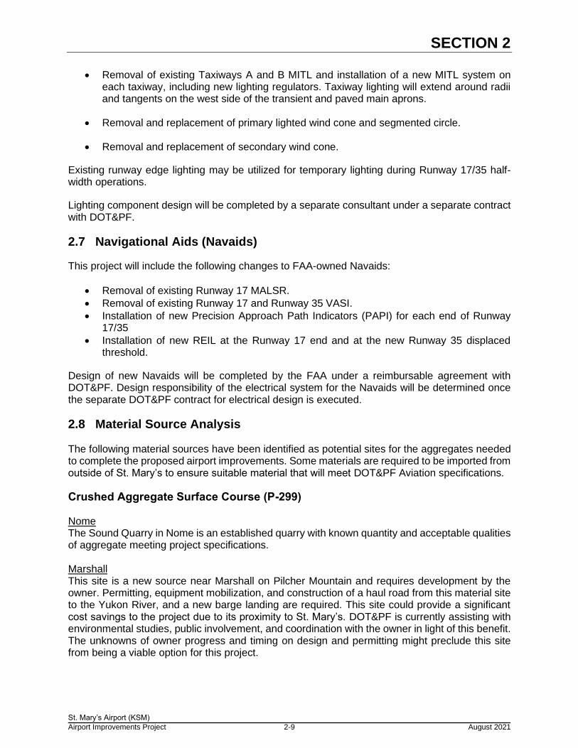
2.7 Navigational Aids (Navaids)
This project will include the following changes to FAA-owned Navaids:
• Removal of existing Runway 17 MALSR.
• Removal of existing Runway 17 and Runway 35 VASI.
• Installation of new Precision Approach Path Indicators (PAPI) for each end of Runway 17/35
• Installation of new REIL at the Runway 17 end and at the new Runway 35 displaced threshold.
Design of new Navaids will be completed by the FAA under a reimbursable agreement with DOT&PF. Design responsibility of the electrical system for the Navaids will be determined once the separate DOT&PF contract for electrical design is executed.
2.8 Material Source Analysis The following material sources have been identified as potential sites for the aggregates needed to complete the proposed airport improvements. Some materials are required to be imported from outside of St. Mary’s to ensure suitable material that will meet DOT&PF Aviation specifications.
Crushed Aggregate Surface Course (P-299) Nome The Sound Quarry in Nome is an established quarry with known quantity and acceptable qualities of aggregate meeting project specifications. Marshall This site is a new source near Marshall on Pilcher Mountain and requires development by the owner. Permitting, equipment mobilization, and construction of a haul road from this material site to the Yukon River, and a new barge landing are required. This site could provide a significant cost savings to the project due to its proximity to St. Mary’s. DOT&PF is currently assisting with environmental studies, public involvement, and coordination with the owner in light of this benefit. The unknowns of owner progress and timing on design and permitting might preclude this site from being a viable option for this project.

SECTION 2
St. Mary’s Airport (KSM)
Airport Improvements Project 2-10 August 2021
Borrow (P-152) The primary source for borrow will be salvaged material excavated from the existing runway, taxiway, and apron areas as well as material available at the Pitkas Point pit as described below. Excavated material will need to be hauled to the stockpile are or Pitkas Point pit and processed prior to use to ensure it meets DOT&PF specifications for borrow, which includes suitable material that passes a 1-inch sieve. Pitkas Point Pitkas Point is the preferred source for any new material required due to the apparent harder sandstone (confirmed by recent test results), as compared to other local material sites. It is important to confirm there is sufficient quantity to supply the project. One concern is unacceptable amounts of Shale mixed in the material. A geotechnical investigation and topographic survey are planned to confirm the site material quality and quantity.
Subbase Course (P-154) Subbase Course (P-154) is available from several existing local material sources, including “West Ridge”, Pitkas Point, St. Mary’s Pit, or suitable excavated soils from the existing runways. This will be a standard FAA P-154 Subbase Course, passing a 3-inch sieve.
Asphalt Aggregates (P-401) Asphalt aggregates have similar requirements to surface course soils with higher degradation values. This material will be imported to the site from either Nome or Marshall.
Crushed Surfacing Base Course (P-209) Similar to the asphalt and surfacing aggregates, the P-209 specification requires higher degradation values that cannot be met by local aggregates; this material will be imported to the site from either Nome or Marshall.
2.9 Barge Haul Analysis Nome It is estimated that this 240-mile (one way) route will take 3.5 days for a single round trip to St. Mary’s carrying approximately 2,200 tons of material. There could be additional delays with this route to wait for suitable tides to enter the mouth of the Yukon River, and weather could impact crossing the Norton Sound. A 10% factor is added to this barge route to account for these factors. Marshall This route is 60 miles (one way) on the Yukon River and will not have to deal with tides or open water weather conditions. Fog can sometimes impede river navigation, but it is not common. No additional cost factor has been added to this route. Current project estimates assume that material will be imported from the more expensive alternative, Nome.

SECTION 2
St. Mary’s Airport (KSM)
Airport Improvements Project 2-11 August 2021
2.10 Barge Landings City of St. Mary’s Barge Landing The City of St. Mary’s barge landing is readily available for use without development. This site requires a 1,200 cubic yard stockpile area (estimated footprint of ~10,000 sf) at the wharf for most of the summer. Haul trucks traveling through the town would create safety and dust concerns and will require coordination with and approval of the City. This barge landing location also requires the use of a longer, steeper haul route as described later in this section. Airport Barge Landing The airport barge landing is dependent on several factors for it to become a viable barge landing for use in this project. These factors include permitting, construction of a new barge landing facility in the Yukon River and associated equipment at the edge of the river, coordination with and potential approval from Boreal Fisheries, and coordination with the community of Saint Mary’s regarding subsistence fisheries at this location. This site is on Airport property, leads to a significantly shorter haul route to the Airport, and the haul route is expected to accommodate larger haul trucks due to the flatter grades. Challenges include potential conflicts with the Boreal Fisheries operations, securing a permitted window for in-water construction of the barge landing that works with construction timing (and river ice), and the impact to subsistence fishing. The barge landing is proposed to be temporary, so all improvements will be removed after construction is complete. Barge Landing Options: Two options will be advanced with the permitting to provide contractors with flexibility, assuming both options are viable:
• Option 1: Causeway into the river with truck haul for offloading the barge; a variation on this would be to drive sheet pile to contain the soil.
• Option 2: Pilings with conveyor for offloading the barge. Both options will be updated with bathymetric survey data, when available. Permitting. Anticipated required permits include:
• Essential Fish Habitat Consultation (National Marine Fisheries Service)
• Title 16 permit (ADF&G)
• Wetland Permit, to be included in the large project permit (USACE)
2.11 Haul Route Analysis St. Mary’s Barge Landing to St. Mary’s Airport This route is an approximately 11-mile round trip from the barge site to the Airport. Drawbacks are steep grades possibly exceeding 10%, trucking through town and occupying the barge landing upland area (material staging) for most of the summer, and road weight restrictions limiting the haul truck sizes. Maintenance of this haul route is expected to be required. Dust impacts in St. Mary’s could be significant at times and will require mitigation measures. Airport Barge Landing to St. Mary’s Airport This route is more direct at 3.2 miles round trip with no grades exceeding 8%. The road is of unknown structure and is expected to require some level of surface enhancement and

SECTION 2
St. Mary’s Airport (KSM)
Airport Improvements Project 2-12 August 2021
maintenance to support the haul trucks. A geotechnical exploration program is proposed for the route to be included as supplemental information for use by the contractor to determine the effort required. This will allow DOT&PF to place enhancement and maintenance costs on the contractor through the bid documents. Current project cost estimates assume that the more expensive St. Mary’s Barge Landing will be used for this project.
2.12 Project Phasing
Construction is anticipated to be completed over two construction seasons. Phase 1 will include importing aggregates to a local airport pit and the construction of the Runway 17 RSA expansion. The remaining phases of work will be in the second construction season and will include resurfacing of all airport surfaces and replacement of all runway and taxiway lighting.
Runway 17/35 operations must be maintained throughout construction; this is a critical phasing element. To accomplish this, the project phasing includes the use of half-width operations on Runway 17/35 during construction within the Runway 17/35 RSA. Half width operations will comply with the FAA Alaska Region Airports Division – Runway Half Width Operation Construction Guidance memorandum and preliminary project phasing meeting this guidance is included in the draft Construction Safety and Phasing Plan (CSPP). Half-width construction will include daylight operations on Runway 17/35 and construction at night with temporary changes to critical airport dimensions as shown below in Table 2-10.
Table 2-10 – Runway 17/35 Half-Width Operation Dimensions
Element Normal Airport
Condition Half-Width Condition
Runway 17/35 Width 150’ 100’1
Runway 17/35 Safety Area Width
300’ 150’
Runway Edge Light Distance from Runway Edge
10’ 2’ – 10’
RSA Transverse Slope 1.0% - 2.0% 2.0% - 5.0% 1This temporary width assumes a portion of the existing RSA embankment will serve as usable runway during construction.

SECTION 3
St Mary’s Airport (KSM)
Airport Improvements Project 3-1 August 2021
3.0 MODIFICATIONS TO AGENCY STANDARDS
3.1 Modifications to DOT&PF Design Standards
There are no proposed modifications to DOT&PF Design Standards.
3.2 Modifications to FAA Design Standards
There are no proposed modifications to FAA Design Standards included in this project.
3.3 Modifications to DOT&PF Construction Standards
There are currently no proposed significant changes to the DOT&PF standard aviation specifications. Existing AASHTOWare Project (AWP) bid items will be used for all bid items, and measurement and payment section of technical specifications will be reviewed to ensure all applicable pay items are included in these specifications.

INTENTIONALLY LEFT BLANK

SECTION 4
St. Mary’s Airport (KSM)
Airport Improvements Project 4-1 August 2021
4.0 COST ESTIMATE
4.1 Engineer’s Estimate
An estimate of construction quantities and associated construction costs is included in Table 4-1 below. This estimate includes costs for barging surfacing aggregates from Nome and hauling to the airport via the St. Mary’s barge landing. If surfacing aggregates are obtained from Marshall and the Airport Barge Landing is used, the unit prices for imported aggregates are expected to be decreased.
Table 4-1 – Preliminary Baseline Construction Estimate
Bid Item Subtotal $ 25,121,405
Construction Engineering (15%) $ 3,768,211
Indirect Cost Allocation Plan (ICAP) (6.34%) $ 1,831,602
Contingency (10%) $ 3,072,122
Plans-in-Hand (PIH) Project Engineer’s Estimate $ 33,793,339
A detailed Project Engineer’s Estimate is included in Appendix B. This estimate is based on design quantities, site inspections, recent bid data for similarly sized airport DOT&PF projects, experience on similar projects, and contacts made with local contractors.

INTENTIONALLY LEFT BLANK

SECTION 5
St. Mary’s Airport (KSM)
Airport Improvements Project 5-1 August 2021
5.0 PROJECT SCHEDULE
5.1 Time Constraints
Hauling of imported materials and stockpiling near the airport will be required during the first construction season. Embankment work to extend the Runway 17 RSA is also expected to occur in the first construction season. Drainage improvements, airfield electrical improvements, Runway 6/24 RSA embankment widening, and resurfacing of both runways, both taxiways, and apron areas are anticipated to be completed in the second year of construction.
5.2 Recommended Schedule
Design, bidding, and construction are expected to follow the approximate schedule outlined below:
• Plans-in-Hand (PIH): 8/20/2021
• Pre-PS&E: 10/12/2021
• Final PS&E: 2/3/2022
• Bidding: March 2022
• Construction (Season 1): Summer 2022
• Construction (Season 2): Summer 2023

INTENTIONALLY LEFT BLANK

Appendix A
APPENDIX A: DRAINAGE CALCULATIONS

INTENTIONALLY LEFT BLANK

K. E
ag
le
Da
te:
8/2
0/2
02
1
RW
Y 1
7-3
5 D
itch
RT
1 (
ST
A 2
2+
00)
Open C
hannel (R
ubble
)Q
=C
IAC
:0.8
(Str
eet)
Left
Bot
.R
ight
Chan.
n=
0.0
30
I (in/h
r):
0.0
7(1
0 y
r, 2
4hr)
Sto
rm E
vent
Qx:
1W
idth
x:1
Slo
pe
Depth
nV
A (
acr
es)
:12.7
4047
(cfs
)(f
t)(f
t/ft
)(f
t)(f
ps)
Q (
cfs
):0.7
13466
0.7
13
46
40.0
06
0.1
20.0
30.9
0
RW
Y 1
7-3
5 D
itch
LT
1 (
ST
A 4
4+
00)
Open C
hannel (R
ubble
)Q
=C
IAC
:0.8
(Str
eet)
Left
Bot
.R
ight
Chan.
n=
0.0
30
I (in/h
r):
0.0
7(1
0 y
r, 2
4hr)
Sto
rm E
vent
Qx:
1W
idth
x:1
Slo
pe
Depth
nV
A (
acr
es)
:5.1
65289
(cfs
)(f
t)(f
t/ft
)(f
t)(f
ps)
Q (
cfs
):0.2
89256
0.2
89
46
40.0
04
0.0
80.0
30.5
5
10 y
r
83
20
15
4th
Ave
nu
e N
E R
ed
mo
nd
, W
A 9
80
52
Te
le: (4
25
) 8
69
-26
70
F
AX
: (4
25
) 8
69
-26
79
Ca
lcu
late
d b
y:
10 y
r

RW
Y 1
7-3
5 D
itch
LT
2 (
ST
A 5
9+
00)
Open C
hannel (R
ubble
)Q
=C
IAC
:0.8
(Str
eet)
Left
Bot
.R
ight
Chan.
n=
0.0
30
I (in/h
r):
0.0
7(1
0 y
r, 2
4hr)
Sto
rm E
vent
Qx:
1W
idth
x:1
Slo
pe
Depth
nV
A (
acr
es)
:0.9
49656
(cfs
)(f
t)(f
t/ft
)(f
t)(f
ps)
Q (
cfs
):0.0
53181
0.0
53
46
40.0
06
0.0
30.0
30.3
3
RW
Y 1
7-3
5 D
itch
RT
2 (
ST
A 5
9+
00)
Open C
hannel (R
ubble
)Q
=C
IAC
:0.8
(Str
eet)
Left
Bot
.R
ight
Chan.
n=
0.0
30
I (in/h
r):
0.0
7(1
0 y
r, 2
4hr)
Sto
rm E
vent
Qx:
1W
idth
x:1
Slo
pe
Depth
nV
A (
acr
es)
:2.3
4068
(cfs
)(f
t)(f
t/ft
)(f
t)(f
ps)
Q (
cfs
):0.1
31078
0.1
31
46
40.0
06
0.0
40.0
30.4
7
10 y
r
10 y
r

RW
Y 1
7-3
5 D
itch
LT
3 (
ST
A 6
6+
00)
Open C
hannel (R
ubble
)Q
=C
IAC
:0.8
(Str
eet)
Left
Bot
.R
ight
Chan.
n=
0.0
30
I (in/h
r):
0.0
7(1
0 y
r, 2
4hr)
Sto
rm E
vent
Qx:
1W
idth
x:1
Slo
pe
Depth
nV
A (
acr
es)
:5.5
80349
(cfs
)(f
t)(f
t/ft
)(f
t)(f
ps)
Q (
cfs
):0.3
125
0.3
12
46
40.0
03
0.1
00.0
30.5
0
TW
Y B
Dit
ch
RT
1 (
ST
A 3
05+
00)
Open C
hannel (R
ubble
)Q
=C
IAC
:0.8
(Str
eet)
Left
Bot
.R
ight
Chan.
n=
0.0
30
I (in/h
r):
0.0
7(1
0 y
r, 2
4hr)
Sto
rm E
vent
Qx:
1W
idth
x:1
Slo
pe
Depth
nV
A (
acr
es)
:4.8
87741
(cfs
)(f
t)(f
t/ft
)(f
t)(f
ps)
Q (
cfs
):0.2
73713
0.2
74
46
40.0
25
0.0
50.0
30.9
810 y
r
10 y
r

INTENTIONALLY LEFT BLANK

Appendix B
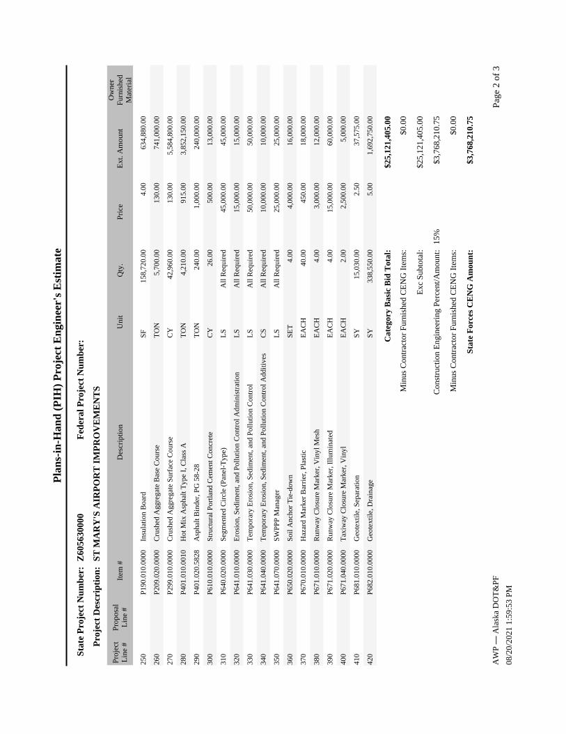
APPENDIX B: AASHTOWARE (AWP) PIH ESTIMATE

INTENTIONALLY LEFT BLANK

Pla
ns-
in-H
and
(P
IH)
Pro
ject
En
gin
eer'
s E
stim
ate
Pro
ject
Des
crip
tion
:
Fed
eral
Pro
ject
Nu
mb
er:
Sta
te P
roje
ct N
um
ber
:
Item
#P
roje
ctL
ine
#D
escr
ipti
onE
xt. A
mou
ntP
rice
Qty
.U
nit
Z60
5630
000
ST
MA
RY
'S A
IRP
OR
T I
MP
RO
VE
ME
NT
S
Ow
ner
Fur
nish
edM
ater
ial
Pro
posa
lL
ine
#
Bas
ic B
idC
ateg
ory:
10C
S P
ipe,
36-
inch
96,0
00.0
015
0.00
D70
1.01
0.00
3664
0.00
LF
20R
ip R
ap2,
250.
0075
.00
D70
1.09
0.00
0030
.00
TO
N
30M
obil
izat
ion
and
Dem
obil
izat
ion
1,00
0,00
0.00
1,00
0,00
0.00
G10
0.01
0.00
00A
ll R
equi
red
LS
40W
orke
r M
eals
and
Lod
ging
, or
Per
Die
m20
0,00
0.00
200,
000.
00G
115.
010.
0000
All
Req
uire
dL
S
50F
ield
Off
ice
25,0
00.0
025
,000
.00
G13
0.01
0.00
00A
ll R
equi
red
LS
60F
ield
Lab
orat
ory
15,0
00.0
015
,000
.00
G13
0.02
0.00
00A
ll R
equi
red
LS
70N
ucle
ar T
esti
ng E
quip
men
t S
tora
ge S
hed
10,0
00.0
010
,000
.00
G13
0.06
0.00
001.
00E
AC
H
80E
ngin
eeri
ng T
rans
port
atio
n (T
ruck
)40
,000
.00
20,0
00.0
0G
131.
010.
0000
2.00
EA
CH
90C
onst
ruct
ion
Sur
veyi
ng b
y th
e C
ontr
acto
r75
,000
.00
75,0
00.0
0G
135.
010.
0000
All
Req
uire
dL
S
100
Ext
ra T
hree
Per
son
Sur
vey
Par
ty7,
500.
0030
0.00
G13
5.02
0.00
0025
.00
HR
110
Con
trac
tor
Qua
lity
Con
trol
Pro
gram
50,0
00.0
050
,000
.00
G20
0.01
0.00
00A
ll R
equi
red
LS
120
Con
trac
tor
Saf
ety
Pla
n C
ompl
ianc
e D
ocum
ent
25,0
00.0
025
,000
.00
G21
0.01
0.00
00A
ll R
equi
red
LS
130
Air
port
Fla
gger
25,0
00.0
025
,000
.00
G70
0.01
0.00
00A
ll R
equi
red
CS
140
Hig
hway
Tra
ffic
Mai
nten
ance
40,0
00.0
040
,000
.00
G71
0.01
0.00
00A
ll R
equi
red
LS
150
Air
port
Lig
htin
g50
0,00
0.00
500,
000.
00L
125.
010.
0000
All
Req
uire
dL
S
160
Air
port
Sig
n, L
-858
45,0
00.0
05,
000.
00L
125.
130.
0000
9.00
EA
CH
170
Tem
pora
ry R
unw
ay L
ight
ing
Sys
tem
85,0
00.0
085
,000
.00
L12
5.18
0.00
00A
ll R
equi
red
LS
180
Sta
ndby
Gen
erat
or a
nd E
nclo
sure
220,
000.
0022
0,00
0.00
L14
5.01
0.00
00A
ll R
equi
red
LS
190
Cle
arin
g24
,500
.00
2,50
0.00
P15
1.01
0.00
009.
80A
CR
E
200
Unc
lass
ifie
d E
xcav
atio
n2,
760,
900.
0015
.00
P15
2.01
0.00
0018
4,06
0.00
CY
210
Bor
row
Mea
sure
d in
Fin
al P
osit
ion
5,13
8,10
0.00
30.0
0P
152.
250.
0000
171,
270.
00C
Y
220
Sub
base
Cou
rse
1,28
5,00
0.00
20.0
0P
154.
010.
0000
64,2
50.0
0C
Y
230
Rem
oval
of
Str
uctu
res
100,
000.
0010
0,00
0.00
P16
5.01
0.00
00A
ll R
equi
red
LS
240
Dus
t P
alli
ativ
e30
0,00
0.00
300,
000.
00P
167.
020.
0000
All
Req
uire
dL
S
Pag
e 1
of 3
AW
P ―
Ala
ska
DO
T&
PF
08/2
0/20
21 1
:59:
53 P
M
Pla
ns-
in-H
and
(P
IH)
Pro
ject
En
gin
eer'
s E
stim
ate
Pro
ject
Des
crip
tion
:
Fed
eral
Pro
ject
Nu
mb
er:
Sta
te P
roje
ct N
um
ber
:
Item
#P
roje
ctL
ine
#D
escr
ipti
onE
xt. A
mou
ntP
rice
Qty
.U
nit
Z60
5630
000
ST
MA
RY
'S A
IRP
OR
T I
MP
RO
VE
ME
NT
S
Ow
ner
Fur
nish
edM
ater
ial
Pro
posa
lL
ine
#
250
Insu
lati
on B
oard
634,
880.
004.
00P
190.
010.
0000
158,
720.
00S
F
260
Cru
shed
Agg
rega
te B
ase
Cou
rse
741,
000.
0013
0.00
P20
9.02
0.00
005,
700.
00T
ON
270
Cru
shed
Agg
rega
te S
urfa
ce C
ours
e5,
584,
800.
0013
0.00
P29
9.01
0.00
0042
,960
.00
CY
280
Hot
Mix
Asp
halt
Typ
e I,
Cla
ss A
3,85
2,15
0.00
915.
00P
401.
010.
0010
4,21
0.00
TO
N
290
Asp
halt
Bin
der,
PG
58-
2824
0,00
0.00
1,00
0.00
P40
1.02
0.58
2824
0.00
TO
N
300
Str
uctu
ral
Por
tlan
d C
emen
t C
oncr
ete
13,0
00.0
050
0.00
P61
0.01
0.00
0026
.00
CY
310
Seg
men
ted
Cir
cle
(Pan
el-T
ype)
45,0
00.0
045
,000
.00
P64
0.02
0.00
00A
ll R
equi
red
LS
320
Ero
sion
, Sed
imen
t, a
nd P
ollu
tion
Con
trol
Adm
inis
trat
ion
15,0
00.0
015
,000
.00
P64
1.01
0.00
00A
ll R
equi
red
LS
330
Tem
pora
ry E
rosi
on, S
edim
ent,
and
Pol
luti
on C
ontr
ol50
,000
.00
50,0
00.0
0P
641.
030.
0000
All
Req
uire
dL
S
340
Tem
pora
ry E
rosi
on, S
edim
ent,
and
Pol
luti
on C
ontr
ol A
ddit
ives
10,0
00.0
010
,000
.00
P64
1.04
0.00
00A
ll R
equi
red
CS
350
SW
PP
P M
anag
er25
,000
.00
25,0
00.0
0P
641.
070.
0000
All
Req
uire
dL
S
360
Soi
l A
ncho
r T
ie-d
own
16,0
00.0
04,
000.
00P
650.
020.
0000
4.00
SE
T
370
Haz
ard
Mar
ker
Bar
rier
, Pla
stic
18,0
00.0
045
0.00
P67
0.01
0.00
0040
.00
EA
CH
380
Run
way
Clo
sure
Mar
ker,
Vin
yl M
esh
12,0
00.0
03,
000.
00P
671.
010.
0000
4.00
EA
CH
390
Run
way
Clo
sure
Mar
ker,
Ill
umin
ated
60,0
00.0
015
,000
.00
P67
1.02
0.00
004.
00E
AC
H
400
Tax
iway
Clo
sure
Mar
ker
, Vin
yl5,
000.
002,
500.
00P
671.
040.
0000
2.00
EA
CH
410
Geo
text
ile,
Sep
arat
ion
37,5
75.0
02.
50P
681.
010.
0000
15,0
30.0
0S
Y
420
Geo
text
ile,
Dra
inag
e1,
692,
750.
005.
00P
682.
010.
0000
338,
550.
00S
Y
Cat
egor
y B
asic
Bid
Tot
al:
$25,
121,
405.
00
$0.0
0
Con
stru
ctio
n E
ngin
eeri
ng P
erce
nt/A
mou
nt:
15%
Min
us C
ontr
acto
r F
urni
shed
CE
NG
Ite
ms:
$0.0
0
$3,7
68,2
10.7
5
Exc
Sub
tota
l:$2
5,12
1,40
5.00
Sta
te F
orce
s C
EN
G A
mou
nt:
$3,7
68,2
10.7
5
Min
us C
ontr
acto
r F
urni
shed
CE
NG
Ite
ms:
$0.0
0
Pag
e 2
of 3
AW
P ―
Ala
ska
DO
T&
PF
08/2
0/20
21 1
:59:
53 P
M

Pla
ns-
in-H
and
(P
IH)
Pro
ject
En
gin
eer'
s E
stim
ate
Pro
ject
Des
crip
tion
:
Fed
eral
Pro
ject
Nu
mb
er:
Sta
te P
roje
ct N
um
ber
:
Item
#P
roje
ctL
ine
#D
escr
ipti
onE
xt. A
mou
ntP
rice
Qty
.U
nit
Z60
5630
000
ST
MA
RY
'S A
IRP
OR
T I
MP
RO
VE
ME
NT
S
Ow
ner
Fur
nish
edM
ater
ial
Pro
posa
lL
ine
#
Bas
ic B
id O
wn
er F
urn
ish
ed M
ater
ial
Tot
al:
$0.0
0
Ind
irec
t C
ost
All
ocat
ion
Pla
n (
ICA
P)
Per
cen
t/A
mou
nt:
6.34
%$1
,831
,601
.64
Cat
egor
y B
asic
Bid
Est
imat
e T
otal
:$3
0,72
1,21
7.39
Cat
egor
y S
ubto
tal
(Pay
Ite
ms
+ S
F C
EN
G +
Fur
n M
ater
ials
):$2
8,88
9,61
5.75
$25,
121,
405.
00P
ay I
tem
Tot
al:
Z60
5630
000
42 I
tem
s
ICA
P A
mou
nt:
$1,8
31,6
01.6
4
SF
CE
NG
Am
oun
t:$3
,768
,210
.75
Ow
ner
Fu
rnis
hed
Mat
eria
ls (
Not
par
t of
th
e C
ontr
act)
:$0
.00
Pro
ject
Est
imat
e T
otal
:$3
0,72
1,21
7.39
Est
imat
e B
id C
onti
nge
ncy
Per
cen
t/A
mou
nt:
$3,0
72,1
21.7
410
.00%
Pro
ject
Est
imat
e T
otal
+ E
stim
ate
Bid
Con
tin
gen
cy:
$33,
793,
339.
13
Pag
e 3
of 3
AW
P ―
Ala
ska
DO
T&
PF
08/2
0/20
21 1
:59:
53 P
M

INTENTIONALLY LEFT BLANK