Embed Size (px)
Citation preview

SI5048U-TUS121440 | TBEN-SI5048U | Version 4.0 US
Off-Grid InverterSUNNY ISLAND 5048-USTechnical Description


SMA America, LLC Legal Restrictions
Technical Description SI5048U-TUS121440 3
Copyright © 2012 SMA America, LLC. All rights reserved.No part of this document may be reproduced, stored in a retrieval system, or transmitted, in any form or by any means, electronic, mechanical, photographic, magnetic or otherwise, without the prior written permission of SMA America, LLC.SMA America, LLC doesn‘t make representations, express or implied, with respect to this documentation or any of the equipment and/or software it may describe, including (with no limitation) any implied warranties of utility, merchantability, or fitness for any particular purpose. All such warranties are expressly disclaimed. Neither SMA America, LLC nor its distributors or dealers nor SMA Solar Technology Canada Inc. nor its distributors or dealers shall be liable for any indirect, incidental, or consequential damages under any circumstances.(The exclusion of implied warranties may not apply in all cases under some statutes, and thus the above exclusion may not apply.)Specifications are subject to change without notice. Every attempt has been made to make this document complete, accurate and up-to-date. Readers are cautioned, however, that SMA America, LLC reserves the right to make changes without notice and shall not be responsible for any damages, including indirect, incidental or consequential damages, caused by reliance on the material presented, including, but not limited to, omissions, typographical errors, arithmetical errors or listing errors in the content material.All trademarks are recognized even if these are not marked separately. Missing designations do not mean that a product or brand is not a registered trademark.
SMA America, LLC3801 N. Havana Street
Denver, CO 80239 U.S.A.

Important Safety Instructions SMA America, LLC
4 SI5048U-TUS121440 Technical Description
IMPORTANT SAFETY INSTRUCTIONSSAVE THESE INSTRUCTIONSThis manual contains important instructions for the following products:
• Sunny Island 5048-USThis manual must be followed during installation and maintenance.
The Sunny Island 5048-US is designed and tested according to international safety requirements, but as with all electrical and electronic equipment, certain precautions must be observed when installing and/or operating the Sunny Island 5048-US. To reduce the risk of personal injury and to ensure the safe installation and operation of the Sunny Island 5048-US, you must carefully read and follow all instructions, cautions and warnings in this manual.Warnings in this documentA warning describes a hazard to equipment or personnel. It calls attention to a procedure or practice, which, if not correctly performed or adhered to, could result in damage to or destruction of part or all of the SMA equipment and/or other equipment connected to the SMA equipment or personal injury.
DANGER
DANGER indicates a hazardous situation which, if not avoided, will result in death or serious injury.
WARNING
WARNING indicates a hazardous situation which, if not avoided, could result in death or serious injury.
CAUTION
CAUTION indicates a hazardous situation which, if not avoided, could result in minor or moderate injury.
NOTICE
NOTICE is used to address practices not related to personal injury.

SMA America, LLC Important Safety Instructions
Technical Description SI5048U-TUS121440 5
Other symbols in this documentIn addition to the safety and hazard symbols described on the previous pages, the following symbol is also used in this manual:
Markings on this productThe following symbols are used as product markings with the following meanings.
InformationThis symbol accompanies notes that call attention to supplementary information that you must know and use to ensure optimal operation of the system.
Warning regarding dangerous voltageThe product works with high voltages. All work on the product must only be performed as described in the documentation of the product.Electric arc hazardsThe product has large electrical potential differences between its conductors. Arc flashes can occur through air when high-voltage current flows. Do not work on the product during operation.Beware of hot surfaceThe product can become hot during operation. Do not touch the product during operation.Observe the operating instructionsRead the documentation of the product before working on it. Follow all safety precautions and instructions as described in the documentation.UL1741 is the standard applied by Underwriters Laboratories to the product to certify that it meets the requirements of the National Electrical Code® and IEEE‑929‑2000. IEEE 929-2000 provides recommendations regarding the proper equipment and functionality necessary to ensure compatible operation when power generation is connected to the utility grid.

General Warnings SMA America, LLC
6 SI5048U-TUS121440 Technical Description
General warningsGeneral warnings
All electrical installations must be done in accordance with the local and National Electrical Code® ANSI/NFPA 70 or the Canadian Electrical Code® CSA C22.1. This document does not and is not intended to replace any local, state, provincial, federal or national laws, regulation or codes applicable to the installation and use of the Sunny Island 5048-US, including without limitation applicable electrical safety codes. All installations must conform with the laws, regulations, codes and standards applicable in the jurisdiction of installation. SMA assumes no responsibility for the compliance or noncompliance with such laws or codes in connection with the installation of the product.The Sunny Island 5048-US contains no user-serviceable parts. For all repair and maintenance, always return the unit to an authorized SMA Service Center.Before installing or using the Sunny Island 5048-US, read all of the instructions, cautions, and warnings in this manual.Before connecting the Sunny Island 5048-US to the electrical utility grid, contact the local utility company. This connection must be made only by qualified personnel.Wiring of the Sunny Island 5048-US must be made by qualified personnel only.

SMA America, LLC Table of Contents
Technical Description SI5048U-TUS121440 7
Table of Contents1 Notes on this Manual. . . . . . . . . . . . . . . . . . . . . . . . . . . . . 151.1 Area of validity . . . . . . . . . . . . . . . . . . . . . . . . . . . . . . . . . . . . . 151.2 Target Group . . . . . . . . . . . . . . . . . . . . . . . . . . . . . . . . . . . . . . 151.3 Additional Information . . . . . . . . . . . . . . . . . . . . . . . . . . . . . . . 151.4 Nomenclature . . . . . . . . . . . . . . . . . . . . . . . . . . . . . . . . . . . . . . 152 The Sunny Island 5048U . . . . . . . . . . . . . . . . . . . . . . . . . . 162.1 Properties . . . . . . . . . . . . . . . . . . . . . . . . . . . . . . . . . . . . . . . . . 162.2 At a Glance . . . . . . . . . . . . . . . . . . . . . . . . . . . . . . . . . . . . . . . 222.3 Scope of Delivery . . . . . . . . . . . . . . . . . . . . . . . . . . . . . . . . . . . 242.4 Required Tools and Resources . . . . . . . . . . . . . . . . . . . . . . . . . 252.5 Identifying the Sunny Island . . . . . . . . . . . . . . . . . . . . . . . . . . . 263 Safety Instructions . . . . . . . . . . . . . . . . . . . . . . . . . . . . . . . 273.1 Important Notes regarding Operation . . . . . . . . . . . . . . . . . . . 273.2 Potential Hazards . . . . . . . . . . . . . . . . . . . . . . . . . . . . . . . . . . . 284 Assembly. . . . . . . . . . . . . . . . . . . . . . . . . . . . . . . . . . . . . . . 304.1 Selecting the Mounting Location. . . . . . . . . . . . . . . . . . . . . . . . 304.2 Mounting the Sunny Island with a Wall Mounting Bracket . . . 334.2.1 Mounting the Sunny Island on a Stone Wall . . . . . . . . . . . . . . . . . . . . . . . . 344.2.2 Mounting the Sunny Island Using Wall Studs. . . . . . . . . . . . . . . . . . . . . . . . 36
5 Opening and Closing. . . . . . . . . . . . . . . . . . . . . . . . . . . . . 375.1 Opening the Sunny Island . . . . . . . . . . . . . . . . . . . . . . . . . . . . 375.2 Closing the Sunny Island. . . . . . . . . . . . . . . . . . . . . . . . . . . . . . 386 Electrical Connection . . . . . . . . . . . . . . . . . . . . . . . . . . . . . 396.1 Grounding . . . . . . . . . . . . . . . . . . . . . . . . . . . . . . . . . . . . . . . . 41

Table of Contents SMA America, LLC
8 SI5048U-TUS121440 Technical Description
6.2 DC terminal. . . . . . . . . . . . . . . . . . . . . . . . . . . . . . . . . . . . . . . . 436.2.1 Safety Precautions/Conditions . . . . . . . . . . . . . . . . . . . . . . . . . . . . . . . . . . . 436.2.2 Cable Sizing . . . . . . . . . . . . . . . . . . . . . . . . . . . . . . . . . . . . . . . . . . . . . . . . . 436.2.3 Cable Protection . . . . . . . . . . . . . . . . . . . . . . . . . . . . . . . . . . . . . . . . . . . . . . 446.2.4 Connecting the Sunny Island to the DC side. . . . . . . . . . . . . . . . . . . . . . . . . 456.3 AC Connection . . . . . . . . . . . . . . . . . . . . . . . . . . . . . . . . . . . . . 466.3.1 Line Fuse . . . . . . . . . . . . . . . . . . . . . . . . . . . . . . . . . . . . . . . . . . . . . . . . . . . . 466.3.2 AC1 (Loads/Sunny Boys) . . . . . . . . . . . . . . . . . . . . . . . . . . . . . . . . . . . . . . . 466.3.3 AC2 (Generator/Grid) . . . . . . . . . . . . . . . . . . . . . . . . . . . . . . . . . . . . . . . . . 486.4 Additional Connections. . . . . . . . . . . . . . . . . . . . . . . . . . . . . . . 506.4.1 Battery Temperature Sensor . . . . . . . . . . . . . . . . . . . . . . . . . . . . . . . . . . . . . 506.4.2 Battery Current Sensor . . . . . . . . . . . . . . . . . . . . . . . . . . . . . . . . . . . . . . . . . 526.4.3 Communication for Multi-device Connection . . . . . . . . . . . . . . . . . . . . . . . . 536.4.4 Multi-function Relay 1 and 2. . . . . . . . . . . . . . . . . . . . . . . . . . . . . . . . . . . . . 556.4.5 BatVtgOut Power Supply . . . . . . . . . . . . . . . . . . . . . . . . . . . . . . . . . . . . . . . 586.4.6 DigIn Digital Input . . . . . . . . . . . . . . . . . . . . . . . . . . . . . . . . . . . . . . . . . . . . . 596.5 Interface for External Communication. . . . . . . . . . . . . . . . . . . . 606.5.1 Connection of the Interface for External Communication . . . . . . . . . . . . . . . 60
7 Control Elements . . . . . . . . . . . . . . . . . . . . . . . . . . . . . . . . 637.1 Display Messages. . . . . . . . . . . . . . . . . . . . . . . . . . . . . . . . . . . 647.2 DC Circuit Breaker . . . . . . . . . . . . . . . . . . . . . . . . . . . . . . . . . . 647.3 Buttons . . . . . . . . . . . . . . . . . . . . . . . . . . . . . . . . . . . . . . . . . . . 657.4 Meaning of the Light Emitting Diodes (LED's) . . . . . . . . . . . . . . 657.5 SD Card . . . . . . . . . . . . . . . . . . . . . . . . . . . . . . . . . . . . . . . . . . 658 Initial Start-up . . . . . . . . . . . . . . . . . . . . . . . . . . . . . . . . . . . 668.1 Requirements. . . . . . . . . . . . . . . . . . . . . . . . . . . . . . . . . . . . . . . 668.2 Starting the Quick Configuration Guide (QCG). . . . . . . . . . . . 668.3 Connecting the Battery Current Sensor. . . . . . . . . . . . . . . . . . . 70

SMA America, LLC Table of Contents
Technical Description SI5048U-TUS121440 9
9 Switching On and Off . . . . . . . . . . . . . . . . . . . . . . . . . . . . 729.1 Switching on . . . . . . . . . . . . . . . . . . . . . . . . . . . . . . . . . . . . . . . 729.2 Stopping (Standby). . . . . . . . . . . . . . . . . . . . . . . . . . . . . . . . . . 739.3 Switching off . . . . . . . . . . . . . . . . . . . . . . . . . . . . . . . . . . . . . . . 749.4 Disconnecting the Device from Voltage Sources. . . . . . . . . . . . 749.5 Reactivating the Device Following Automatic Shutdown . . . . . 7410 Operation . . . . . . . . . . . . . . . . . . . . . . . . . . . . . . . . . . . . . . 7610.1 Menu Structure . . . . . . . . . . . . . . . . . . . . . . . . . . . . . . . . . . . . . 7710.2 Changing Parameters . . . . . . . . . . . . . . . . . . . . . . . . . . . . . . . . 8010.3 Direct Access (to the parameters) . . . . . . . . . . . . . . . . . . . . . . . 8110.4 Compact Meters . . . . . . . . . . . . . . . . . . . . . . . . . . . . . . . . . . . . 8110.5 Entering the Installer Password . . . . . . . . . . . . . . . . . . . . . . . . . 8510.6 Display Messages (Overview) . . . . . . . . . . . . . . . . . . . . . . . . . 8710.7 Parameter Display. . . . . . . . . . . . . . . . . . . . . . . . . . . . . . . . . . . 9010.8 Display of Events. . . . . . . . . . . . . . . . . . . . . . . . . . . . . . . . . . . . 9010.9 Display of Warnings and Failures. . . . . . . . . . . . . . . . . . . . . . . 9111 Archiving Data on an SD Card . . . . . . . . . . . . . . . . . . . . . 9211.1 Inserting the SD Card . . . . . . . . . . . . . . . . . . . . . . . . . . . . . . . . 9511.2 Removing the SD Card . . . . . . . . . . . . . . . . . . . . . . . . . . . . . . . 9611.3 Saving and Loading Parameters . . . . . . . . . . . . . . . . . . . . . . . . 9611.4 Writing Log Data . . . . . . . . . . . . . . . . . . . . . . . . . . . . . . . . . . . 9611.5 Status Messages . . . . . . . . . . . . . . . . . . . . . . . . . . . . . . . . . . . . 9711.6 Updating the Firmware . . . . . . . . . . . . . . . . . . . . . . . . . . . . . . . 9812 Additional Functions . . . . . . . . . . . . . . . . . . . . . . . . . . . . 10112.1 Load Shedding . . . . . . . . . . . . . . . . . . . . . . . . . . . . . . . . . . . . 10112.2 Sleep Mode . . . . . . . . . . . . . . . . . . . . . . . . . . . . . . . . . . . . . . 10312.3 Time-Controlled Operation . . . . . . . . . . . . . . . . . . . . . . . . . . . 103

Table of Contents SMA America, LLC
10 SI5048U-TUS121440 Technical Description
12.4 Overload and Short-Circuit Behavior . . . . . . . . . . . . . . . . . . . 10312.5 Device Faults and Autostart . . . . . . . . . . . . . . . . . . . . . . . . . . 10312.6 Automatic Frequency Control (AFC) . . . . . . . . . . . . . . . . . . . . 10412.7 Time-Controlled Standby. . . . . . . . . . . . . . . . . . . . . . . . . . . . . 10412.8 Reaction in Case of Faults in a 3-phase system . . . . . . . . . . . 10413 Battery Management. . . . . . . . . . . . . . . . . . . . . . . . . . . . 10513.1 Battery Temperature . . . . . . . . . . . . . . . . . . . . . . . . . . . . . . . . 10513.2 Start Options. . . . . . . . . . . . . . . . . . . . . . . . . . . . . . . . . . . . . . 10613.3 State of Charge (SOC) and State of Health (SOH) . . . . . . . . 10613.4 Charge Control . . . . . . . . . . . . . . . . . . . . . . . . . . . . . . . . . . . . 10713.4.1 Boost Charge . . . . . . . . . . . . . . . . . . . . . . . . . . . . . . . . . . . . . . . . . . . . . . . 10913.4.2 Full Charge . . . . . . . . . . . . . . . . . . . . . . . . . . . . . . . . . . . . . . . . . . . . . . . . . 10913.4.3 Equalization Charge . . . . . . . . . . . . . . . . . . . . . . . . . . . . . . . . . . . . . . . . . . 11013.4.4 Manual Equalization Charge . . . . . . . . . . . . . . . . . . . . . . . . . . . . . . . . . . . 11013.4.5 Silent Mode. . . . . . . . . . . . . . . . . . . . . . . . . . . . . . . . . . . . . . . . . . . . . . . . . 11113.5 Battery Preservation Mode . . . . . . . . . . . . . . . . . . . . . . . . . . . 11113.6 Battery Diagnostics . . . . . . . . . . . . . . . . . . . . . . . . . . . . . . . . . 11313.7 Battery Lead Resistance . . . . . . . . . . . . . . . . . . . . . . . . . . . . . 11314 Connecting External Sources . . . . . . . . . . . . . . . . . . . . . 11414.1 Generator . . . . . . . . . . . . . . . . . . . . . . . . . . . . . . . . . . . . . . . . 11414.1.1 Parallel Connection . . . . . . . . . . . . . . . . . . . . . . . . . . . . . . . . . . . . . . . . . . . 11414.1.2 Generator Start Options . . . . . . . . . . . . . . . . . . . . . . . . . . . . . . . . . . . . . . . 11614.1.3 Generator Operation . . . . . . . . . . . . . . . . . . . . . . . . . . . . . . . . . . . . . . . . . 11814.1.4 Manual Generator Operation . . . . . . . . . . . . . . . . . . . . . . . . . . . . . . . . . . 11814.1.5 Automatic Generator Operation. . . . . . . . . . . . . . . . . . . . . . . . . . . . . . . . . 12014.1.6 Limits and Power Adjustment . . . . . . . . . . . . . . . . . . . . . . . . . . . . . . . . . . . . 12214.1.7 Run Times . . . . . . . . . . . . . . . . . . . . . . . . . . . . . . . . . . . . . . . . . . . . . . . . . . 12414.1.8 Operation in Conjunction with PV Inverters. . . . . . . . . . . . . . . . . . . . . . . . . 12514.1.9 Stopping the Generator . . . . . . . . . . . . . . . . . . . . . . . . . . . . . . . . . . . . . . . 125

SMA America, LLC Table of Contents
Technical Description SI5048U-TUS121440 11
14.1.10 Stopping the Sunny Island . . . . . . . . . . . . . . . . . . . . . . . . . . . . . . . . . . . . . 12614.1.11 Faults . . . . . . . . . . . . . . . . . . . . . . . . . . . . . . . . . . . . . . . . . . . . . . . . . . . . . . 12614.2 Grid . . . . . . . . . . . . . . . . . . . . . . . . . . . . . . . . . . . . . . . . . . . . 12714.2.1 Voltage and Frequency Limits . . . . . . . . . . . . . . . . . . . . . . . . . . . . . . . . . . . 12714.2.2 Starting the Sunny Island. . . . . . . . . . . . . . . . . . . . . . . . . . . . . . . . . . . . . . . 12714.2.3 Operation During Grid Loss in Grid-Tied Backup Configuration. . . . . . . . . 12714.2.4 Backup Operation and ”Anti-Islanding” . . . . . . . . . . . . . . . . . . . . . . . . . . . 12714.2.5 Grid Reconnection . . . . . . . . . . . . . . . . . . . . . . . . . . . . . . . . . . . . . . . . . . . 12814.2.6 Grid Operation . . . . . . . . . . . . . . . . . . . . . . . . . . . . . . . . . . . . . . . . . . . . . . 12814.2.7 Grid Failure . . . . . . . . . . . . . . . . . . . . . . . . . . . . . . . . . . . . . . . . . . . . . . . . . 13214.2.8 Faults . . . . . . . . . . . . . . . . . . . . . . . . . . . . . . . . . . . . . . . . . . . . . . . . . . . . . . 13214.2.9 Limits and Power Adjustment . . . . . . . . . . . . . . . . . . . . . . . . . . . . . . . . . . . . 13314.2.10 Operation in Conjunction with PV Inverters. . . . . . . . . . . . . . . . . . . . . . . . . 13314.3 Generator and Grid . . . . . . . . . . . . . . . . . . . . . . . . . . . . . . . . 13415 Relays . . . . . . . . . . . . . . . . . . . . . . . . . . . . . . . . . . . . . . . . 13616 Multicluster Operation. . . . . . . . . . . . . . . . . . . . . . . . . . . 13816.1 Communication between the Sunny Islands . . . . . . . . . . . . . . 13816.2 Initial Commissioning of the Multicluster System. . . . . . . . . . . 14016.3 Switching a Multicluster System On and Off . . . . . . . . . . . . . 14116.3.1 Activation / Startup. . . . . . . . . . . . . . . . . . . . . . . . . . . . . . . . . . . . . . . . . . . 14116.3.2 Stopping and Switching off . . . . . . . . . . . . . . . . . . . . . . . . . . . . . . . . . . . . . 14116.4 Generator Operation . . . . . . . . . . . . . . . . . . . . . . . . . . . . . . . 14216.5 Behavior with Different Charge States . . . . . . . . . . . . . . . . . . 14216.6 Testing Multicluster communication. . . . . . . . . . . . . . . . . . . . . 14216.7 Automatic Frequency Control (AFC) . . . . . . . . . . . . . . . . . . . . 14316.8 Firmware Update . . . . . . . . . . . . . . . . . . . . . . . . . . . . . . . . . . 14316.9 Fault Handling in a Multicluster System . . . . . . . . . . . . . . . . . 14316.10 Grid Operation. . . . . . . . . . . . . . . . . . . . . . . . . . . . . . . . . . . . 14316.11 Emergency generator load support . . . . . . . . . . . . . . . . . . . . 144

Table of Contents SMA America, LLC
12 SI5048U-TUS121440 Technical Description
17 PV Inverter . . . . . . . . . . . . . . . . . . . . . . . . . . . . . . . . . . . . 14517.1 Connection to the Off-Grid Power System
(Protected Loads Panel) . . . . . . . . . . . . . . . . . . . . . . . . . . . . . 14517.2 Setting the off-grid parameters (Sunny Boy) . . . . . . . . . . . . . . 14617.3 Configuration . . . . . . . . . . . . . . . . . . . . . . . . . . . . . . . . . . . . . 14617.4 Sunny Boy Parameter Settings . . . . . . . . . . . . . . . . . . . . . . . . 14617.5 Frequency Shift Power Control (FSPC) . . . . . . . . . . . . . . . . . . 14718 Maintenance and Care . . . . . . . . . . . . . . . . . . . . . . . . . . 14918.1 Enclosure. . . . . . . . . . . . . . . . . . . . . . . . . . . . . . . . . . . . . . . . . 14918.2 Cleaning the Fans . . . . . . . . . . . . . . . . . . . . . . . . . . . . . . . . . . 14918.3 Display . . . . . . . . . . . . . . . . . . . . . . . . . . . . . . . . . . . . . . . . . . 14918.4 Function. . . . . . . . . . . . . . . . . . . . . . . . . . . . . . . . . . . . . . . . . . 14918.5 Battery. . . . . . . . . . . . . . . . . . . . . . . . . . . . . . . . . . . . . . . . . . . 14918.6 Disposal . . . . . . . . . . . . . . . . . . . . . . . . . . . . . . . . . . . . . . . . . 14919 Parameter lists . . . . . . . . . . . . . . . . . . . . . . . . . . . . . . . . . 15019.1 Display Values . . . . . . . . . . . . . . . . . . . . . . . . . . . . . . . . . . . . 15019.1.1 Inverter Meters (110#) . . . . . . . . . . . . . . . . . . . . . . . . . . . . . . . . . . . . . . . . 15019.1.2 Battery Meters (120#) . . . . . . . . . . . . . . . . . . . . . . . . . . . . . . . . . . . . . . . . 15419.1.3 External Meters (130#) . . . . . . . . . . . . . . . . . . . . . . . . . . . . . . . . . . . . . . . 15519.1.4 Charge Controller (140#) (not UL-certified) . . . . . . . . . . . . . . . . . . . . . . . . 15719.2 Adjustable parameters . . . . . . . . . . . . . . . . . . . . . . . . . . . . . . 15919.2.1 Inverter Settings (210#) . . . . . . . . . . . . . . . . . . . . . . . . . . . . . . . . . . . . . . . 15919.2.2 Battery Settings (220#). . . . . . . . . . . . . . . . . . . . . . . . . . . . . . . . . . . . . . . . 16019.2.3 External Settings (230#) . . . . . . . . . . . . . . . . . . . . . . . . . . . . . . . . . . . . . . . 16319.2.4 Relay Settings (240#) . . . . . . . . . . . . . . . . . . . . . . . . . . . . . . . . . . . . . . . . . 17119.2.5 System Settings (250#). . . . . . . . . . . . . . . . . . . . . . . . . . . . . . . . . . . . . . . . 18119.2.6 Password Setting (280#) . . . . . . . . . . . . . . . . . . . . . . . . . . . . . . . . . . . . . . 183

SMA America, LLC Table of Contents
Technical Description SI5048U-TUS121440 13
19.3 Diagnosis (300#) . . . . . . . . . . . . . . . . . . . . . . . . . . . . . . . . . 18319.3.1 Inverter Diagnosis (310#). . . . . . . . . . . . . . . . . . . . . . . . . . . . . . . . . . . . . . 18319.3.2 Battery Diagnosis (320#) . . . . . . . . . . . . . . . . . . . . . . . . . . . . . . . . . . . . . . 18619.3.3 External Diagnosis (330#) . . . . . . . . . . . . . . . . . . . . . . . . . . . . . . . . . . . . . 19019.4 Events, Warnings and Failures (History) . . . . . . . . . . . . . . . . . 19019.4.1 Failure / Event (400#) . . . . . . . . . . . . . . . . . . . . . . . . . . . . . . . . . . . . . . . . 19019.5 Functions in Operation . . . . . . . . . . . . . . . . . . . . . . . . . . . . . . 19119.5.1 Operation (500#). . . . . . . . . . . . . . . . . . . . . . . . . . . . . . . . . . . . . . . . . . . . 19119.6 Direct Access to the Parameters . . . . . . . . . . . . . . . . . . . . . . . 19419.6.1 Direct Access (600#) . . . . . . . . . . . . . . . . . . . . . . . . . . . . . . . . . . . . . . . . . 194
20 Troubleshooting . . . . . . . . . . . . . . . . . . . . . . . . . . . . . . . . 19520.1 Failure Confirmation . . . . . . . . . . . . . . . . . . . . . . . . . . . . . . . . 19520.2 Autostart Handling . . . . . . . . . . . . . . . . . . . . . . . . . . . . . . . . . 19520.3 Master Slave Handling . . . . . . . . . . . . . . . . . . . . . . . . . . . . . . 19520.4 Handling Pending Failures During the Booting Procedure . . . 19620.5 Display of Failures and Events . . . . . . . . . . . . . . . . . . . . . . . . 19620.6 Events . . . . . . . . . . . . . . . . . . . . . . . . . . . . . . . . . . . . . . . . . . . 19720.6.1 Category INV . . . . . . . . . . . . . . . . . . . . . . . . . . . . . . . . . . . . . . . . . . . . . . . 19720.6.2 Category BAT . . . . . . . . . . . . . . . . . . . . . . . . . . . . . . . . . . . . . . . . . . . . . . . 19720.6.3 Category GEN . . . . . . . . . . . . . . . . . . . . . . . . . . . . . . . . . . . . . . . . . . . . . . 19820.6.4 GRD Category . . . . . . . . . . . . . . . . . . . . . . . . . . . . . . . . . . . . . . . . . . . . . . 19820.6.5 Category REL . . . . . . . . . . . . . . . . . . . . . . . . . . . . . . . . . . . . . . . . . . . . . . . 19920.6.6 Category SYS . . . . . . . . . . . . . . . . . . . . . . . . . . . . . . . . . . . . . . . . . . . . . . . 20020.7 Failure Categories. . . . . . . . . . . . . . . . . . . . . . . . . . . . . . . . . . 20020.8 Warnings and Failure Messages . . . . . . . . . . . . . . . . . . . . . . 20120.8.1 Category INV . . . . . . . . . . . . . . . . . . . . . . . . . . . . . . . . . . . . . . . . . . . . . . . 20120.8.2 Category BAT . . . . . . . . . . . . . . . . . . . . . . . . . . . . . . . . . . . . . . . . . . . . . . . 20220.8.3 Category EXT . . . . . . . . . . . . . . . . . . . . . . . . . . . . . . . . . . . . . . . . . . . . . . . 20220.8.4 Category GEN . . . . . . . . . . . . . . . . . . . . . . . . . . . . . . . . . . . . . . . . . . . . . . 20420.8.5 Category GRD . . . . . . . . . . . . . . . . . . . . . . . . . . . . . . . . . . . . . . . . . . . . . . 204

Table of Contents SMA America, LLC
14 SI5048U-TUS121440 Technical Description
20.8.6 Category RLY . . . . . . . . . . . . . . . . . . . . . . . . . . . . . . . . . . . . . . . . . . . . . . . 20420.8.7 Category SYS . . . . . . . . . . . . . . . . . . . . . . . . . . . . . . . . . . . . . . . . . . . . . . . 20520.8.8 AUX Category. . . . . . . . . . . . . . . . . . . . . . . . . . . . . . . . . . . . . . . . . . . . . . . 20720.9 Troubleshooting . . . . . . . . . . . . . . . . . . . . . . . . . . . . . . . . . . . 20920.10 Procedure During Emergency Charge Mode . . . . . . . . . . . . . 21221 Accessories . . . . . . . . . . . . . . . . . . . . . . . . . . . . . . . . . . . . 21522 Technical Data . . . . . . . . . . . . . . . . . . . . . . . . . . . . . . . . . 21623 Glossary . . . . . . . . . . . . . . . . . . . . . . . . . . . . . . . . . . . . . . 21924 Contact . . . . . . . . . . . . . . . . . . . . . . . . . . . . . . . . . . . . . . . 226

SMA America, LLC Notes on this Manual
Technical Description SI5048U-TUS121440 15
1 Notes on this ManualThis manual describes the functionality, mounting, electrical connections and operation of the Sunny Island 5048‑US. Store this manual where it will be accessible at all times.
1.1 Area of validityThis manual is valid for the Sunny Island 5048‑US (SI 5048U), firmware version 6.002/6.000 and later.
1.2 Target GroupThis manual is for qualified personnel. Qualified personnel has received training and has knowledge of the design and function of the device and has demonstrable practical experience of mounting, connecting and commissioning of the device. Qualified personnel is trained to deal with the dangers and hazards involved in installing electric devices.
1.3 Additional InformationYou will find further information on special topics such as selecting and using PV inverters in off-grid power systems in the download area of www.SMA-America.com.
1.4 NomenclatureIn this document SMA Solar Technology America, LLC is referred to in the following as SMA.The syntax specified here for menus and parameters applies throughout the entire manual:Menu: Menu number, hash and menu name (150# Compact Meters)Parameter: Menu number, dot, parameter number and parameter name (150.01 GdRmgTm)

The Sunny Island 5048U SMA America, LLC
16 SI5048U-TUS121440 Technical Description
2 The Sunny Island 5048U2.1 PropertiesThe Sunny Island is a bidirectional inverter (battery inverter and charger) for off-grid power systems. The Sunny Island supplies loads on the off-grid side and charges battery banks with the energy from grid-feeding units connected on the AC side.The comfortable support of AC and DC coupling, as well as the expandability of the systems formed with the Sunny Island guarantee highest flexibility. In addition, innovative technology allows the Sunny Island to achieve a maximum efficiency of more than 95 %. Optimized for partial load operation, it impresses with low open-circuit and standby consumption. Due to the high overload capabilities and the integrated output management, there is no need to oversize the Sunny Island.The operation of up to 3 devices in a 1‑phase parallel system, of 3 devices in a 3‑phase system or of up to 4 devices in a double split‑phase system enables the Sunny Island to establish off‑grid power supply systems with a power of between 2 kW ... 20 kW. In Multicluster systems, powers of up to as much as 100 kW are possible. Thanks to its sophisticated generator management, the Sunny Island can control connected diesel generators in a particularly low‑stress and fuel‑saving manner. It can also be integrated into the public grid. The Sunny Island can also deactivate loads automatically if the battery does not provide sufficient electrical energy.The critical component in off-grid power systems, the battery, is monitored diligently and utilized optimally. The intelligent battery management records the battery's charge level precisely. This makes possible an improved utilization of the battery capacity, which also means that smaller and thus more cost-effective batteries can be used without affecting performance.In order to prevent premature aging caused by incorrect charging and frequent deep discharge, the Sunny Island has an intelligent charge control and reliable deep discharge protection. Because of these functions the battery service life can be greatly extended in comparison with simpler devices.Despite its complex functioning, the Sunny Island is easy to configure. All the settings required for operation can be quickly and easily programmed in a few steps using the ”Quick Configuration Guide”. By employing the concept of central operation referred to as ”Single Point of Operation”, the system/cluster parameters are only set on the master device, and all other devices adopt the configuration automatically. The easy-to-understand menu navigation allows quick access to all important data, even while the system is running. An SD card provides uncomplicated system control, and thus facilitates any service work.
The Sunny Island monitors the set voltage and frequency limits on the grid and generator. If these limits are not observed, it disconnects from the external source without interruption and changes to off-grid operation. The Sunny Island also has an integrated anti-islanding feature which will stop the production of electricity when the grid goes down.
Saving Data and EventsAlways use the SD card to save data and events. In case of a failure SMA can thus help you quickly.
SMA America, LLC The Sunny Island 5048U
Technical Description SI5048U-TUS121440 17
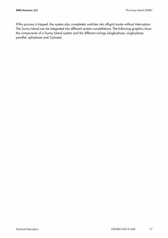
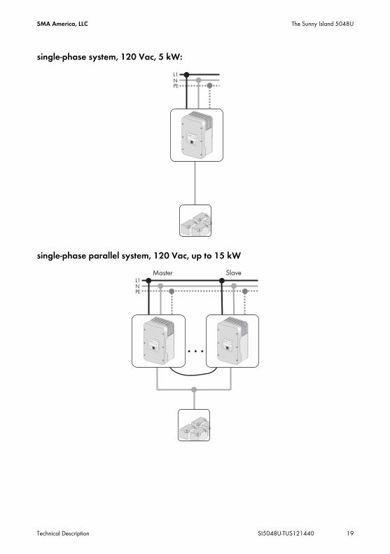
If this process is tripped, the system also completely switches into off-grid mode without interruption. The Sunny Island can be integrated into different system constellations. The following graphics show the components of a Sunny Island system and the different wirings (single-phase, single-phase parallel, split-phase and 3-phase).

The Sunny Island 5048U SMA America, LLC
18 SI5048U-TUS121440 Technical Description
Components of a Sunny Island System
SMA America, LLC The Sunny Island 5048U
Technical Description SI5048U-TUS121440 19
single-phase system, 120 Vac, 5 kW:
single-phase parallel system, 120 Vac, up to 15 kW

The Sunny Island 5048U SMA America, LLC
20 SI5048U-TUS121440 Technical Description
split-phase system, 240 Vac, 10 kW
3-phase system, 120/208 Vac, 15 kW

SMA America, LLC The Sunny Island 5048U
Technical Description SI5048U-TUS121440 21
Double Split‑Phase System, 240 Vac, 20 kW
Multicluster TechnologyRefer to the manual of the Multicluster Box for informations about Multicluster Technology.

The Sunny Island 5048U SMA America, LLC
22 SI5048U-TUS121440 Technical Description
2.2 At a GlanceThe following figure provides an overview of all control elements and connections of the Sunny Island:

SMA America, LLC The Sunny Island 5048U
Technical Description SI5048U-TUS121440 23
Marker DescriptionA DisplayB LEDs showing device operationC Control buttonsD Slot for the SD cardE Opening for the additional connections area (insertion of the cables via conduits)F Connection area for additional connectionsG Opening for the additional connections area (insertion of the cables via conduits)H Rubber connection block for the additional connections area
(insertion of the cable without conduits)I DC Connection AreaK Opening for the DC connection area
(insertion of DC+, DC‒and the grounding conductor).L Opening for AC2 connection (insertion of the line L, N and PE)M AC connection areaN Opening for AC1 connection (insertion of the line L, N and PE)O DC Circuit Breaker

The Sunny Island 5048U SMA America, LLC
24 SI5048U-TUS121440 Technical Description
2.3 Scope of DeliveryCheck the delivery for completeness. Check the packaging and the Sunny Island for externally visible damage.Contact your supplier in case of damage to the packaging. Contact your dealer if you find any damage on the Sunny Island or if there are parts missing in the delivery.
Keeping the packagingKeep the packaging in case you need to return the inverter or its accessories.
Marker Number DesignationA 1 Sunny IslandB 1 Wall mounting bracketC 2 Fan grillsD 1 Battery temperature sensorE 3 Filler plugsF 3 Counter nut for filler plugsG 1 RJ45 cable, blackH 1 Silicone tubeI 1 Rubber plugs for inserting one cableK 2 Rubber plugs for inserting 2 cablesL 1 SD Card

SMA America, LLC The Sunny Island 5048U
Technical Description SI5048U-TUS121440 25
2.4 Required Tools and ResourcesThe following tools and materials are required in order to mount and install the Sunny Island 5048‑US:
M 2 M6x10 mm screws and locking washers for connecting the Sunny Island with the wall mounting bracket.
N 1 Technical DescriptionO 1 Test ReportP 2 4-pole print terminal for connecting the battery temperature sensor
and current sensorQ 2 3-pole print terminal for the connection of relays 1 and 2R 1 RS485 PiggyBack (optional)S 2 RJ45 cable, white (optional)
Tools (not included in delivery)Bootlace ferrulesCable knifeCombination pliersCrimping tool for terminal lugs (suitable for cable cross-sections of up to 2/0 AWG)Diagonal cutting pliersDrillDrill bit (e.g. masonry or wood bit), fastener 3/8 in. or Ø 10 mmFlat-head screwdriver 0.4 x 1⁄8 in. (2.5 mm) 1.0 x 3⁄8 in. (10 mm) /1.0 x 1⁄4 in. (5.5 mm)Flathead screwdriver SZS 1.0 x 6.5Hexagon‑socket wrench 1⁄8 in. bis 5⁄16 in. (3 mm to 8 mm)MultimeterOpen-end/box wrenches or socket wrenches in the sizes 10/19/24/30Phillips screwdriver, PH1 and PH2Spirit levelTorque wrench 35 in‑lbs. − 50 in‑lbs. (4 Nm − 5 Nm) with flat-head screwdriver adapters in the sizes 3⁄8 in. / 1⁄4 in./ 1⁄8 in. (10/5.5/2.5 mm) and SZS 1.0 x 6.5Insulation stripping tool
Marker Number Designation

The Sunny Island 5048U SMA America, LLC
26 SI5048U-TUS121440 Technical Description
2.5 Identifying the Sunny IslandIdentify the Sunny Island by the serial number and the device type on the type plate. The type plate is on the right side of the enclosure.
Material (not included in delivery)Cable tiesHeat shrink tubingHexagon bolts, 5⁄16 in. x 23⁄8 in. (8 mm x 60 mm), washersWall anchors for the wall mounting bracket (e.g. SX 10)

SMA America, LLC Safety Instructions
Technical Description SI5048U-TUS121440 27
3 Safety Instructions3.1 Important Notes regarding OperationFollow all operating and safety instructions in this manual. If these instructions are ignored, a significant danger of injury or death arises and damage to the device, system or plant may also result. Carefully read the safety instructions before installing and commissioning the device. Store the manual at an easily accessible location.
DANGER
Danger to life due to high voltages in the Sunny Island. Risk of death or serious injury due to electric shock.
• All work on the Sunny Island must only be carried out by qualified personnel.• Work on the Sunny Island should only be carried out as described in this manual.• All listed safety instructions must be followed.
NOTICE!
Destruction of the Sunny Island due to parallel connection of Sunny Island inverters which are set to different grid voltages.
• Always employ Sunny Island inverters of the same type within a system.• Do not connect Sunny Island inverters in parallel with grid voltages set to different
values.NOTICE!
Batteries may be destroyed due to deep discharge.The self‑consumption of the Sunny Island discharges the battery. In standby mode, this load is about 4 W and about 25 W in idle mode.
• If you install the Sunny Island and do not wish to use it immediately, switch the Sunny Island off (see section 9.3 ”Switching off” (page 74)).
• If you want to decommission the Sunny Island for a long period, switch the Sunny Island off (see section 9.3 ”Switching off” (page 74)).
Connection RequirementsBe sure to observe all valid regional standards and guidelines.

Safety Instructions SMA America, LLC
28 SI5048U-TUS121440 Technical Description
3.2 Potential Hazards
Installation AltitudeThe Sunny Island has been designed for use at elevations of up to 9840 ft. (3000 m) above sea level. Contact SMA before using the device at elevations above 9840 ft. (3000 m).A performance loss of 0.5 % per 330 ft (100 m) is to be expected starting at an elevation of 6560 ft. (2000 m) above sea level!
DANGER
Electric shock through contact with live component parts. Death or serious injuries.In order to ensure sufficient protection against contact, comply with the following under consideration of the manual:
• Ensure that the Sunny Island is correctly mounted.• Ensure that the Sunny Island is properly grounded.• Ensure that all connections are correctly made.• Ensure that the enclosure lid is firmly closed.
DANGER
Danger to life due to high voltages in the stand‑alone grid. Risk of death or serious injury due to electric shock.The Sunny Island can start on its own.
• Before working on the off-grid power system disconnect all AC and DC power sources.
DANGER
Death hazard if the Sunny Island is used to supply energy to life-sustaining medical devices.This device was not developed to power life-sustaining medical devices.
• Do not use the Sunny Island in systems in which a power outage might result in personal injury.

SMA America, LLC Safety Instructions
Technical Description SI5048U-TUS121440 29
NOTICE!
Destruction of the Sunny Island if installed in improper locations.The Sunny Island is only suited for indoor installation and corresponds to degree of protection NEMA 1 (IP30, or IP40 with inserted SD card).
• Do not expose the Sunny Island to humidity, rain or direct sunlight.

Assembly SMA America, LLC
30 SI5048U-TUS121440 Technical Description
4 Assembly4.1 Selecting the Mounting Location
DANGER
Danger of death if installed in improper locations. Death or serious burns.Despite careful construction, a fire can occur with electrical devices.
• Do not mount the Sunny Island on flammable construction materials.• Do not mount the Sunny Island near highly flammable materials.• Do not mount the Sunny Island in potentially explosive areas.
CAUTION
Risk of injury through contact with hot enclosure parts during operation.Burns to the body will result.
• Mount the inverter in such a way that the enclosure cannot be touched inadvertently.
CAUTION
Risk of injury due to the Sunny Island falling during transport. Physical injury (fractures or crushing) and damage to the Sunny Island.
• Consider the Sunny Island's weight of 139 lb. (63 kg).• Use the recessed grips or steel bars for transporting and mounting.
Overheating of the Sunny Island due to close proximity to other Sunny Island inverters in areas with high ambient temperatures.If several inverters have been installed in areas with high ambient temperatures, the independent cooling of individual inverters needs to be guaranteed.If needed, increase the distance between the individual inverters and provide enough fresh air to ensure the optimal operation of the inverters.The Sunny Island switches itself off automatically in the event of overtemperature.

SMA America, LLC Assembly
Technical Description SI5048U-TUS121440 31
Observe the following conditions during mounting:• The mounting method and mounting location must be suitable for the weight and dimensions of
the Sunny Island.• Mount on a solid surface.• The installation location must be accessible at all times.• The ambient temperature must be between -13 °F (–25 °C) and 122 °F (+50 °C).• Do not expose the Sunny Island to direct sunlight to avoid power reduction (derating) due to
excessive heating.• Install the Sunny Island that way, that the display is at eye level in order to allow the operating
status to be read at all times.• Install vertically or tilted backwards by 45° max.• Never install the device with a forward tilt.• Do not mount in a horizontal position.• The connection area may not point upwards.• The room air can have a humidity of up to 100%, but this must not be condensing.
• In a living area, do not mount the unit on plasterboard walls etc. in order to avoid audible vibrations.The Sunny Island can make noises when in use which can be considered a nuisance when installed in a living area.

Assembly SMA America, LLC
32 SI5048U-TUS121440 Technical Description
• Maintain the minimum distances to walls, other devices and objects as represented in the illustration. In order to maintain sufficient ventilation, when installing the Sunny Island a minimum clearance of 12 in. (30 cm) at the sides and top must be maintained. Operation and reading are made easier by installing the Sunny Island with its display at eye level, and by keeping a distance of 20 in. (50 cm) from the front.
• All external cables are connected through the underside of the enclosure. Therefore a minimum clearance of 20 in (50 cm) must be observed here.

SMA America, LLC Assembly
Technical Description SI5048U-TUS121440 33
4.2 Mounting the Sunny Island with a Wall Mounting Bracket

Assembly SMA America, LLC
34 SI5048U-TUS121440 Technical Description
4.2.1 Mounting the Sunny Island on a Stone Wall
1. Place the wall mounting bracket against a suitable wall for mounting and align using a level. Mark the position of the drill holes using the wall mounting bracket. When doing this, use at least 1 hole on the left side and 1 hole on the right side of the wall mounting bracket.
2. Check the mounting location for the presence of current-carrying cables. If there are current-carrying cables at the mounting location, select a different mounting location.
3. Drill holes on the markings for them.4. Secure the wall mounting bracket to the wall using
appropriate screws and washers. Tighten the screws in a clockwise direction.
CAUTION
Risk of injury due to the Sunny Island falling. Physical injury (fractures or crushing) and damage to the Sunny Island.
• If mounting onto a stone wall, ensure that the wall can carry the weight of the Sunny Island.
• If mounting onto a wooden wall with studs, ensure that the wall mounting bracket is firmly connected with all studs and that the studs can carry the weight of the Sunny Island.
CAUTION
Risk of injury due to the Sunny Island falling during transport or mounting. Physical injury (fractures or crushing) and damage to the Sunny Island.
• Consider the Sunny Island's weight of 139 lb. (63 kg).• Use the recessed grips or steel bars for transporting and mounting.

SMA America, LLC Assembly
Technical Description SI5048U-TUS121440 35
5. Attach the Sunny Island to the wall mounting bracket.
6. Screw the Sunny Island to the wall mounting bracket on both sides using the screws (M6x10) provided. Tighten the screws clockwise.
7. Make sure that the device is securely in place.
8. Close the recessed grips with the fan grills provided. To help you identify the sides, the fan grills are marked with ”links/left” and ”rechts/right” on the inside.
The Sunny Island is mounted using the wall mounting bracket.

Assembly SMA America, LLC
36 SI5048U-TUS121440 Technical Description
4.2.2 Mounting the Sunny Island Using Wall Studs
If the Sunny Island is to be mounted on wall studs, then use the holes in the wall mounting bracket as shown in the figures. Ensure that the wall mounting bracket is positioned at least over one wall stud. Note that the wall mounting bracket is designed to mount on a single wall stud or on 2 wall studs. When mounting to wall studs use minimum of four 5/16 in. (8 mm) lag screws with a minimum length of 2 in. (50 mm).
If two or more Sunny Island inverters have to be installed, mount the inverters on two studs each in order to get better cooling. Make sure that the wall where you intend to install the Sunny Island is vertical and can carry the weight of the Sunny Island (139 Ibs, 63 kg) on a long-term basis.
Otherwise proceed as per the mounting on a stone wall (see section 4.2.1 ”Mounting the Sunny Island on a Stone Wall” (page 34)).
CAUTION
Risk of injury due to the Sunny Island falling. Physical injury (fractures or crushing) and damage to the Sunny Island.
• If mounting onto a stone wall, ensure that the wall can carry the weight of the Sunny Island.
• If mounting onto a wooden wall with studs, ensure that the wall mounting bracket is firmly connected with all studs and that the studs can carry the weight of the Sunny Island.

SMA America, LLC Opening and Closing
Technical Description SI5048U-TUS121440 37
5 Opening and ClosingThe enclosure of the Sunny Island has a removable lid. Remove the enclosure lid only when installing the device or for required maintenance or repair work.
5.1 Opening the Sunny Island1. Stop the Sunny Island (see section 9.2 ”Stopping (Standby)” (page 73)).2. Disconnect the Sunny Island from voltage sources (see section 9.4 ”Disconnecting the Device
from Voltage Sources” (page 74)).3. Ensure that the system cannot be accidentally switched on again.
4. Loosen all 6 allen screws on the enclosure lid and set them aside.
5. Remove the enclosure lid and set it aside. The Sunny Island is open.
WARNING
Danger to life due to high voltages in the Sunny Island. Risk of death or serious injury due to electric shock.
• Wait 15 minutes before opening the Sunny Island, until its capacitors are discharged.

Opening and Closing SMA America, LLC
38 SI5048U-TUS121440 Technical Description
5.2 Closing the Sunny Island
1. Place the enclosure lid onto the enclosure and fasten with the 6 screws and the corresponding washers in the sequence depicted on the right. Tighten the screws to a torque of 53 in‑lbs. (6 Nm).
2. Commission the Sunny Island as described in section 9.1 ”Switching on” (page 72) The Sunny Island is closed and in operation.
DANGER
Electric shock due to live enclosure lid. Death or serious injuries.• Fasten the washers for all 6 screws with the toothing facing toward the enclosure lid.
Tighten the Screws with Washers in the Correct OrderTighten the screws with 53 in-lbs (6 Nm) torque in the order shown. The toothing of the washers must face toward the enclosure lid.

SMA America, LLC Electrical Connection
Technical Description SI5048U-TUS121440 39
6 Electrical ConnectionAll cables are fed through the openings on the bottom side of the device (see next illustration) and connected to the appropriate connection terminals on the Sunny Island.
Use cable ducts to install the cables on the DC and AC sides on the Sunny Island. The cable ducts guarantee a dust-free and waterproof installation of the cables in the enclosure and also provide strain relief for the cable connection. Close all unused openings in the enclosure using the appropriate filler plugs.Use the provided terminal blocks to connect the cables inside the Sunny Island enclosure in a manner conforming to the appropriate standards.Obtain an overview of the different components and connection areas of the Sunny Island 2.2 ”At a Glance” (page 22)).Refer to the table below for the appropriate torque values and wire sizes.
Terminal Bolt clamp Wire Size Wire typeDC connections 50 in‑lbs. (5.7 Nm) AWG 10 - AWG 2/0
(6 mm² − 70 mm²)Only use copper conductors. These must be rated for at least 167°F (75 °C). Do not use fine-wire strands.

Electrical Connection SMA America, LLC
40 SI5048U-TUS121440 Technical Description
An overview of the different components and their connection areas of the Sunny Island 5048U can be found in section 2.2 ”At a Glance” (page 22).Detailed installation descriptions of the connections are provided in the following sections:
• Grounding (section 6.5 ”Interface for External Communication” (page 60))• DC connection (section 6.2 ”DC terminal” (page 43))• AC connection (section 6.3 ”AC Connection” (page 46))• Battery temperature sensor (section 6.4.1 ”Battery Temperature Sensor” (page 50))• Battery current sensor (section 6.4.2 ”Battery Current Sensor” (page 52))• Communication for multi-device connection (section 6.4.3 ”Communication for Multi-device
Connection” (page 53))• Multi-function relay 1 and 2 (section 6.4.4 ”Multi-function Relay 1 and 2” (page 55))• External communication (section 6.5 ”Interface for External Communication” (page 60)).
AC connections 22 in-lbs. − 39 in-lbs. (2.5 Nm − 4.5 Nm)
AWG 4 (25 mm²) Only use copper conductors. These must be rated for at least 167°F (75 °C). Do not use fine-wire strands.
Additional Connections 5 − 7 in. lbs.(0.56 Nm − 0.79 Nm)
AWG 30 − AWG 12(0.05 mm² - 4 mm²)
Only use copper conductors. These must be rated for at least 167°F (75 °C).
Terminal Bolt clamp Wire Size Wire type
SMA America, LLC Electrical Connection
Technical Description SI5048U-TUS121440 41
6.1 GroundingWARNING
Risk of lethal electric shock. • Fuse the sub‑distribution of the generator or the power distribution grid at input AC2
of the Sunny Island with an overcurrent protective device (Branch Circuit Protection).• Ensure that the overcurrent protective device complies with the specifications of the
National Electrical Code®, ANSI/NFPA 70• Use an overcurrent protective device for a maximum 70 A.
WARNING
Risk of lethal electric shock due to faulty grounding.To allow different types of grounding, the N connection of the Sunny Island is NOT connected to PE at the factory. However, since a connection between N and PE is required for correct operation, this must be done outside of the device.
• Before commissioning, connect the Sunny Island 4548‑US/6048‑US and all other components of the stand‑alone grid to a grounded grid.
• Take the National Electrical Code®, ANSI/NFPA 70, and all locally applicable standards and regulations into consideration.
External grounding of the negative pole of the batteryExternal grounding of the negative pole of the batteries is possible, because the batteries and the grid side are galvanically insulated within the Sunny Island.
• Dimension the cross‑section of the protective conductor sufficiently. Thus you are ensuring that in the event of a fault the high currents occurring can be discharged with an external grounding.
• If grounding of the negative pole of the battery is necessary, assemble this outside of the Sunny Island.

Electrical Connection SMA America, LLC
42 SI5048U-TUS121440 Technical Description
Connecting the grounding conductor
1. Install a conduit with a diameter of 11/2 in. (38.1 mm) at the opening in the center of the Sunny Island. Attach the conduit in the inside of the Sunny Island using the appropriate nut.
2. Pull the cabling through the supply line from the inside of the distribution board into the enclosure of the Sunny Island.
3. Remove the protective insulation from the groundig conductor.4. Plug the grounding conductor into the DC connection block for grounding and tighten the screw
to a torque of 50 in.-lbs. (5.7 Nm). The grounding conductor is connected.
Calculating the cross‑section of a grounding conductorSMA cannot state generally valid values for the cross‑section of the grounding conductor required for the external grounding of the battery. The cable dimensions depend on the type and size of the battery connected, the external fuse (DC side) and the material used in the grounding cable.
Calculating the Required Grounding Conductor Cross‑section According to Applicable StandardsAn exact calculation of the grounding conductor cross‑section must take account of the regionally applicable standards and guidelines (e.g National Electric Code® Article 250.122).

SMA America, LLC Electrical Connection
Technical Description SI5048U-TUS121440 43
6.2 DC terminal
6.2.1 Safety Precautions/ConditionsConnect a suitable battery to the DC side (see section 22 ”Technical Data” (page 216)). The DC connection must observe all applicable local ordinances and guidelines.
6.2.2 Cable Sizing
Example of Cable SizingWith a 48 V battery voltage and an outgoing AC power of 5 000 W, a current of up to 140 A flows through the SI 5048U battery cable.
NOTICE
Function impairments of devices on the DC busbar.The Sunny Island is not suitable for use with DC supply grids. Function impairment can occur on devices installed on the DC side of a Sunny Island with cables exceeding 98 ft. (30 m) and with a flexible connection.
• Only use fixed installations.• Do not use cables of lengths greater than 98 ft. (30 m) between the Sunny Island
and the battery and/or DC device.
WARNING
Danger to life through chemical burns in the event of leaking acid.Acid can escape in the event of improper handling of the battery.
• Observe all safety indications and warnings provided by the battery manufacturer.• Use special (insulated) tools to mount and install the battery.• Provide sufficient ventilation in the room in which the batteries are. When gasses are
produced by the batteries, these cannot be allowed to collect.
Keep the Cables to the Battery as Short as PossibleThe battery cables should be as short as possible. Long cables and insufficient cable diameters reduce the system efficiency as well as the overload capabilities. Do not lay the battery lead under plaster or in armored plastic pipes.Choice of Cable Cross-sectionsSMA recommends choosing cable cross-sections greater than those given byNEC 250.122 in the case of cable lengths exceeding 32.8 ft (10 m).

Electrical Connection SMA America, LLC
44 SI5048U-TUS121440 Technical Description
The current flowing through the battery cable causes a power loss and a drop in voltage with every meter of plain battery cable. You can use the following table to find the power loss and voltage drop associated with different cable cross-sections.
Example:For a 32.8 ft. (10-meter) distance between the Sunny Island and the battery, at least 65.6 ft. (20 m) of cable are needed (distance there and back). Using a cross-section of AWG 1/0 (50 mm²), 140 A (current flowing through the battery cable) cause a power loss of 170 W in total and an effective voltage drop of 1.2 V.Calculation of the Average Nominal Current of the BatteryYou can calculate the average nominal current of the connected battery using the following formula:
IBat = Nominal current of the batteryPAC = AC power of the inverterUBat = Nominal voltage of the batteryηINV = Efficiency of the inverter at a given AC power
6.2.3 Cable ProtectionIn addition to the internal DC circuit breaker, install a separate, external fuse as close as possible to the battery. Install a suitable fuse plug for the fuse according to the maximum specified DC currents.
Cable Cross-section Power loss Voltage dropAWG 1/0 (50 mm²) 2.6 W/ft. (8,5 W/m) 18 mV/ft. (60 mV/m)AWG 2/0 (70 mm²) 1.8 W/ft. (6 W/m) 14 mV/ft. (45 mV/m)
DANGER
Electric shock resulting from insufficient protection of the DC lines. Death or serious burns.• Check whether external line protection is present.• If no external line protection is present, observe the following:
– Lay the DC cables so that ground faults and short‑circuits cannot occur.– Install an additional current‑limiting fuse outside of the Sunny Island.
When doing so, observe all applicable local standards and guidelines.

SMA America, LLC Electrical Connection
Technical Description SI5048U-TUS121440 45
6.2.4 Connecting the Sunny Island to the DC side
Requirements• 1 conduit with a diameter of 11/2 in. (38.1 mm) is installed at the opening in the middle of the
Sunny Island (see section 6.1 ”Grounding” (page 41)). • The conduit is attached inside the Sunny Island with a suitable nut.
Installing the DC connection1. Pull the positive DC cable through the conduit from the distribution board into the enclosure of
the Sunny Island.2. Pull the negative DC cable through the conduit from the distribution board into the enclosure of
the Sunny Island.3. Remove the protective insulation from the positive and the negative DC cable.
4. Plug the negative DC lines into the "DC‒" connection block and tighten the screw to a torque of 50 in.-lbs. (5.7 Nm).
5. Plug the positive DC lines in to the "DC+" connection block and tighten the screw to a torque of 50 in.-lbs. (5.7 Nm).
WARNING
Risk of lethal electric shock.• Connect the external fuse and the battery cable to the battery only after all
installation work has been completed.
DC Connection AreaThe space between the conductor and the connection area must be clean. This way a transition resistance and the heating of the terminals is reduced.The Sunny Island has a MAX DC terminal rated for 2x #2/0 AWG for DC+, DC- and PE.

Electrical Connection SMA America, LLC
46 SI5048U-TUS121440 Technical Description
6.3 AC Connection
6.3.1 Line FuseYou must connect the Sunny Island via a sub‑distribution to the stand‑alone grid and any external source present.Fit the sub‑distribution with appropriate miniature circuit‑breakers and observe all locally applicable standards and guidelines.
6.3.2 AC1 (Loads/Sunny Boys)The sub‑distribution of the stand‑alone grid (e.g. consumer, PV inverter, wind power inverter) is to be connected to output AC1 of the Sunny Island.If you want to secure individual load circuits in a 120 V grid separately, install miniature circuit‑breakers and fuses with a rated current of no more than 20 A.If larger miniature circuit‑breakers are used, or miniature circuit‑breakers that blow more slowly, the Sunny Island cannot trip them.
DC CablesDo not connect any other components to the DC cables. Other components must be connected directly to the battery via separate cables.The Sunny Island has a MAX DC terminal rated for 2x#2/0 for Pos, Neg and PE.
Fitting the sub‑distribution with miniature circuit‑breakersThe sub‑distribution must be equipped with appropriate circuit breakers. Observe all locally applicable standards and guidelines.Maximum permissible input currentThe maximum input current allowed on the Sunny Island is 56 A. Higher input currents must not be connected to the Sunny Island.No all‑pole isolator on the Sunny IslandThe Sunny Island is not equipped with an all‑pole isolator. The neutral conductor (N conductor) is looped through the device and the N terminals of AC1 and AC2 are connected inside the Sunny Island.
Cable lengths in 1‑phase, parallel, split‑phase‑, double split‑phase‑ and 3‑phase systemsThe AC lines between the Sunny Island and the sub‑distribution of a system must have the same cable cross‑section and the same length for all parallel connected devices. Distributing loads and AC feed‑ins in multiple‑phase systemsDistribute the feed‑in capacity and the consumed power of the loads and AC feed‑in generators as equally as possible across all plant phases.
SMA America, LLC Electrical Connection
Technical Description SI5048U-TUS121440 47
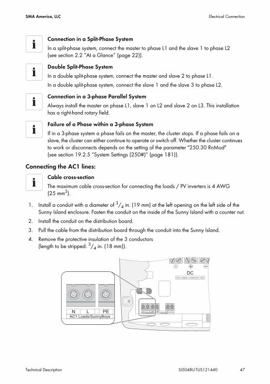
Connecting the AC1 lines:
1. Install a conduit with a diameter of 3/4 in. (19 mm) at the left opening on the left side of the Sunny Island enclosure. Fasten the conduit on the inside of the Sunny Island with a counter nut.
2. Install the conduit on the distribution board.3. Pull the cable from the distribution board through the conduit into the Sunny Island.4. Remove the protective insulation of the 3 conductors
(length to be stripped: 3/4 in. (18 mm)).
Connection in a Split‑Phase SystemIn a split‑phase system, connect the master to phase L1 and the slave 1 to phase L2 (see section 2.2 ”At a Glance” (page 22)).Double Split‑Phase SystemIn a double split‑phase system, connect the master and slave 2 to phase L1.In a double split‑phase system, connect the slave 1 and the slave 3 to phase L2.Connection in a 3‑phase Parallel SystemAlways install the master on phase L1, slave 1 on L2 and slave 2 on L3. This installation has a right‑hand rotary field.Failure of a Phase within a 3‑phase SystemIf in a 3‑phase system a phase fails on the master, the cluster stops. If a phase fails on a slave, the cluster can either continue to operate or switch off. Whether the cluster continues to work or disconnects depends on the setting of the parameter "250.30 RnMod" (see section 19.2.5 ”System Settings (250#)” (page 181)).
Cable cross‑sectionThe maximum cable cross‑section for connecting the loads / PV inverters is 4 AWG (25 mm2).

Electrical Connection SMA America, LLC
48 SI5048U-TUS121440 Technical Description
5. Insert PE into the terminal labeled "AC1 Loads/Sunny Boys" and tighten the fastening screw with a torque of 22 in-lbs. − 39 in-lbs. (2.5 Nm − 4.5 Nm). Use a torque wrench with flat-head screwdriver bit SZS 1.0 x 6.5.
6. Insert N and L into the terminals labeled "AC1 Loads/Sunny Boys" and tighten the fastening screws with a torque of 22 in-lbs. − 39 in-lbs. (2.5 Nm − 4.5 Nm). Use a torque wrench with flat-head screwdriver bit SZS 1.0 x 6.5.
The AC1 cables are connected.
6.3.3 AC2 (Generator/Grid)The sub‑distribution of the generator or power distribution grid is to be connected at input AC2 of the Sunny Island.
Cable lengths in 1‑phase, parallel, split‑phase‑, double split‑phase‑ and 3‑phase systemsThe AC cables between all Sunny Island and the generator/grid in a system must have the same size and length.1‑phase parallel systemIn the case of 1‑phase parallel systems, also connect the generator or the grid to all slaves on AC2. The cable cross‑sections and cable lengths used must be identical.Distribution of Loads and AC Feed‑In Generators in Multi‑Phase SystemsDistribute the feed‑in capacity and consumption power of the loads as well as the AC feed‑in generators as equally as possible across all system phases.Split‑Phase SystemIn a split‑phase system, connect the master to phase L1 and the slave 1 to phase L2 (see also section 2.2 ”At a Glance” (page 22)).Double Split‑Phase SystemIn a double split‑phase system, connect the master and slave 2 to phase L1.In a double split‑phase system, connect the slave 1 and the slave 3 to phase L2.3‑phase systemAlways install the master on phase L1, slave 1 on L2 and slave 2 on L3. This installation has a right‑hand rotary field.

SMA America, LLC Electrical Connection
Technical Description SI5048U-TUS121440 49
Connecting the AC2 Lines (Generator/Grid):
1. Install a conduit with a diameter of 3/4 in. (19 mm) at the right opening on the left side of the Sunny Island enclosure. Fasten the conduit on the inside of the Sunny Island with a counter nut.
2. Install the conduit on the distribution board.3. Pull the cable from the distribution board through the conduit into the Sunny Island.4. Remove the protective insulation of the 3 conductors (length to be stripped: 3/4 in. (18 mm)).5. Insert PE into the terminal labeled "AC2 Gen/Grid" and tighten the fastening screw with a
torque of 22 in-lbs. − 39 in-lbs. (2.5 Nm − 4.5 Nm). Use a torque wrench with flat-head screwdriver bit SZS 1.0 x 6.5.
6. Insert N and L into the terminals labeled "AC2 Gen/Grid" and tighten the fastening screws with a torque of 22 in-lbs. − 39 in-lbs. (2.5 Nm − 4.5 Nm). Use a torque wrench with flat-head screwdriver bit SZS 1.0 x 6.5.
Additional Fuses in the SystemIf there are no additional fuses installed between the generator or power distribution grid and the Sunny Island, the Sunny Island knows whether it has a connection to the power distribution grid/to the generator. The Sunny Island can then draw current from the power distribution grid/from the generator.If there are additional fuses or switches installed between the Sunny Island and the power distribution grid/the generator, the Sunny Island can not determine whether fuses or switches are separated or whether there is no voltage available from the power distribution grid/the generator. In either case the Sunny Island cannot charge its battery and the consumers that are in operation will discharge the Sunny Island battery.Check the additional fuses and switches regularly in order that the Sunny Island battery only discharges when there is no voltage available from the power distribution grid/the generator.
Cable cross‑sectionThe maximum cable cross‑section for connecting the generator is 4 AWG (25 mm²).

Electrical Connection SMA America, LLC
50 SI5048U-TUS121440 Technical Description
6.4 Additional ConnectionsFor installing the connections described below, feed the cables through the specified holes in the cable insert. Plugs for sealing the RJ45 communication cable for internal and external communication are provided in the rubber terminal block upon delivery. Combining plugs allows you to establish up to 4 cable entries (2 plugs without entry, 1 with 1 entry and 2 with 2 entries). Use the plugs with entries as needed to connect the communication cables.
6.4.1 Battery Temperature SensorThe battery temperature sensor measures the temperature of the connected battery. This is necessary since the optimum charging voltage for a battery strongly depends on the temperature. Further information is provided in section 13.4 ”Charge Control” (page 107).A battery temperature sensor (included in the delivery) must be connected in order to operate the Sunny Island. In case of a fault (short-circuit, cable break), the Sunny Island operates in a safe setting, which over time, however, leads to insufficient battery charging. A warning indicating that the defective battery temperature sensor should be replaced immediately is displayed.

SMA America, LLC Electrical Connection
Technical Description SI5048U-TUS121440 51
Connecting the Battery Temperature Sensor
1. Pierce the appropriate place on the cable insert with a pointed object.2. Starting from the outside, feed the cables with wire-end sleeves through the hole in the Sunny
Island.
3. Connect the cables correspondingly to the ”BatTmp” connection of the 4-pole print terminal included in delivery.
4. Tighten the terminals (torque: 5 in‑lbs. ‑ 7 in‑lbs. (0.56 Nm ‑ 0.79 Nm)).5. Insert the 4-pole print terminal into the ”BatTmp” socket on the Sunny Island.6. Attach the battery temperature sensor externally to one of the battery cells. Choose a spot
between two cells and the middle area of the battery bank. The heat generation during operation is the greatest here.
NOTICE
Destruction of the battery through deep discharge as a result of the installation of an unsuitable battery temperature sensor.
• Only use the battery temperature sensor included in the scope of delivery.• Do not drill holes into the battery to install the battery temperature sensor.
Battery Temperature Sensor in a clusterA battery temperature sensor is provided with each Sunny Island. Only one battery temperature is needed for one cluster. Connect the temperature sensor to the master of the cluster.
Polarity of the CablesThe polarity of the two cables is irrelevant for the functioning of the battery temperature sensor.

Electrical Connection SMA America, LLC
52 SI5048U-TUS121440 Technical Description
6.4.2 Battery Current SensorIn addition to the internal measurement, the Sunny Island provides the possibility to measure the battery current via a shunt. You need this function if you intend to operate additional DC generators and DC loads in your off-grid power system. In a cluster, only one battery current sensor is needed; it is connected to the master of the cluster.
Example:
Connecting the Battery Current Sensor
NOTICE
Destruction of the battery due to the connection of additional DC devices.If additional DC devices are installed in an off‑grid system, the internal Sunny Island current measurement becomes inaccurate. The charge current can no longer be set exactly and as a result will destroy the battery.
• Install an external battery current sensor (shunt).

SMA America, LLC Electrical Connection
Technical Description SI5048U-TUS121440 53
1. Pierce the appropriate place on the cable insert with a pointed object.2. Starting from the outside, feed the cables with bootlace ferrules through the hole in the Sunny
Island.3. Connect the cables correspondingly to the ”BatCur” connection of the 4-pole print terminal
included in the delivery.4. Tighten the terminals (torque: 5 in‑lbs. ‑ 7 in‑lbs. (0.56 Nm ‑ 0.79 Nm)).5. Insert the 4-pole print terminal into the ”BatCur” socket on the Sunny Island. The battery current sensor is installed.
6.4.3 Communication for Multi-device ConnectionThe Sunny Island can be connected in parallel, split-phase or in a 3-phase system with other Sunny Island devices in order to increase the overall power. The devices communicate with each other through an RJ45 communication cable. A black RJ45 cable is provided with each Sunny Island. You need the cable in order to establish an (internal) communication between several Sunny Island devices. The maximum total length of the communication bus may not exceed 98 ft. (30 m). If you operate only one Sunny Island in your system, the cable is not required.Proceed as follows to implement the connection:1. Remove one of the two plugs from the cable insert.2. Feed the RJ45 cable from the outside through the plugs inside the Sunny Island master.3. Remove the terminating resistor from the ”ComSyncOut” socket of the master and plug it into
the ”CompSyncIn” socket of the master.4. Plug the RJ45 cable into the ”ComSyncOut” socket.
Use Cables of Intrinsically Safe CircuitsUse cables of intrinsically safe circuits for the connection of battery current sensors. ”Intrinsically safe” means here that the cable is double-insulated and that the wire melts but the insulation remains intact in the event of a short-circuit. In addition, the cable is not combustible. In order to avoid measuring errors, make sure to use twisted cables.Installation InformationThe battery current sensor must be looped around the negative pole of the battery. In addition, the contact of that battery current sensor which is connected to the Sunny Island (1) must be connected to the terminal ”BatCur+” (see following figure).
• Positive battery current means that the battery is discharging (current from the battery).
• Negative battery current means that the battery is charging (current into the battery).
Commissioning the Battery Temperature SensorWhen connecting a battery current sensor to the Sunny Island, the device's internal offset must be adjusted during the first commissioning of the off-grid power system. To do this, proceed as described in section 8.3 ”Connecting the Battery Current Sensor” (page 70).

Electrical Connection SMA America, LLC
54 SI5048U-TUS121440 Technical Description
5. Connect the Sunny Island master to the slave.
Number of slaves Connection Procedure1 slave • Take the RJ45 cable leading away from the master, introduce
it into the Sunny Island slave and plug it into the ”ComSyncIn” socket.
• Leave the termination resistor plugged into the ”ComSyncOut” socket.
The Sunny Island master and slave are connected.2 slaves • Take the RJ45 cable leading away from the master, introduce
it into the Sunny Island slave 1 and plug it into the ”ComSyncIn” socket there.
• Remove the terminating resistor from the ”ComSyncOut” socket in the Sunny Island slave 1.
• Plug the RJ45 cable included in delivery into the ”ComSyncOut” socket of the slave 1.
• Take the RJ45 cable leading away from the slave 1, introduce it into the Sunny Island slave 2 and plug it into the ”ComSyncIn” socket there.
The Sunny Island master and the slaves are connected.Master Slave 1 Slave 2
terminationresistor
location
terminationresistorlocation

SMA America, LLC Electrical Connection
Technical Description SI5048U-TUS121440 55
6.4.4 Multi-function Relay 1 and 2The Sunny Island offers you several options for the control of internal and external processes. For this purpose, two multi-function relays are integrated into the Sunny Island to which you can assign functions using the ”241.01 Rly1Op” and ”241.02 Rly2Op” parameters (see section 15 ”Relays” (page 136)).We recommend connecting the load shedding and generator request functions to the master, since, if a failure occurs, the slave may be waiting for a confirmation, but the master continues to operate and the device can at least operate in a limited capacity.
Connection to the Relay Contact
1. Pierce the appropriate place on the cable insert with a pointed object.2. Starting from the outside, feed the cables with wire-end sleeves through the hole in the Sunny
Island.3. Cut an appropriate piece from the silicone tube (included in the delivery) and pull it over the
wires.
Operating Principles of the RelaysThe relays are changeover contacts; they can be used as normally closed contacts (NCC) or as normally open contacts (NOC).You can only assign one function to each relay!
WARNING
Danger to life from electric shock due to incorrect insulation.• Securely disconnect the relay cable from the communication area and the AC area.• Strip the insulated conductors of the relay cable.• Sheathe all relay cables installed using the silicone tube provided.• Do not operate the device without the silicone tube.
Electrical Connection SMA America, LLC
56 SI5048U-TUS121440 Technical Description
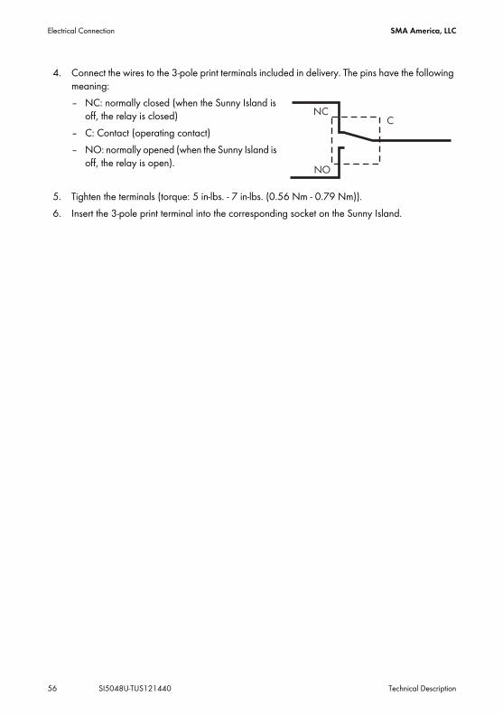
4. Connect the wires to the 3-pole print terminals included in delivery. The pins have the following meaning:– NC: normally closed (when the Sunny Island is
off, the relay is closed)– C: Contact (operating contact)– NO: normally opened (when the Sunny Island is
off, the relay is open).
5. Tighten the terminals (torque: 5 in‑lbs. ‑ 7 in‑lbs. (0.56 Nm ‑ 0.79 Nm)).6. Insert the 3-pole print terminal into the corresponding socket on the Sunny Island.

SMA America, LLC Electrical Connection
Technical Description SI5048U-TUS121440 57
Power Contactor for Load SheddingThe Sunny Island can automatically switch off loads to protect the batteries from deep discharge. To do this, an external (AC or DC) power contactor must be installed between the Sunny Island and the loads (see section 12.1 ”Load Shedding” (page 101)).Installing the Power Supply of a DC Power Contactor for Load Shedding (e.g., relay2):
1. Wire the A1 coil connector of the power contactor to the connection terminal NO (relay2).2. Wire the connection terminal C (relay2) to the connection terminal BatVtgOut +.3. Wire the A2 coil connector of the power contactor to the connection terminal ”BatVtgOut –”. The control circuit of the power contactor is installed.
Power Supply of the DC Power ContactorA 48 V voltage is present in the battery‑supplied control circuit.
• Load the BatVtgOut terminals with a maximum 0.75 A.
A2
A1
Load-Sheddingcontactor

Electrical Connection SMA America, LLC
58 SI5048U-TUS121440 Technical Description
Generator startThe Sunny Island can control generators. The Sunny Island directly supports generators that can be started/stopped using a single contact.
6.4.5 BatVtgOut Power SupplyThe battery voltage is conducted to the outside at these terminals. The battery voltage is fused at both poles by PTC resistors (max. 0.75 A). Depending on the internal temperature of the Sunny Island, the tripping threshold is at over 0.75 A.This connection can be used, for example, to supply a DC contactor for load shedding.Connecting the BatVtgOut Power Supply1. Pierce the appropriate place on the cable insert with a pointed object.2. Starting from the outside, feed the cables with wire-end sleeves through the hole in the Sunny
Island.3. Connect the cables to the ”BatVtgOut” connection of the 4-pole print terminal.4. Tighten the print terminal screws (torque: 5 in‑lbs. ‒ 7 in‑lbs. (0.56 Nm ‒ 0.79 Nm)). The BatVtgOut power supply is connected.
Default Setting of the RelaysBy default, relay 1 is set to the generator start function ”AutoGn” and relay 2 is set to the load shed function ”AutoLodSoc”.
SMA America, LLC Electrical Connection
Technical Description SI5048U-TUS121440 59
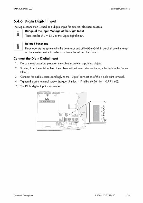
6.4.6 DigIn Digital InputThe DigIn connection is used as a digital input for external electrical sources.
Connect the DigIn Digital Input1. Pierce the appropriate place on the cable insert with a pointed object.2. Starting from the outside, feed the cables with wire-end sleeves through the hole in the Sunny
Island.3. Connect the cables correspondingly to the ”DigIn” connection of the 4-pole print terminal.4. Tighten the print terminal screws (torque: 5 in‑lbs. ‒ 7 in‑lbs. (0.56 Nm ‒ 0.79 Nm)). The DigIn digital input is connected.
Range of the Input Voltage at the DigIn InputThere can be 5 V − 63 V at the DigIn digital input.
Related FunctionsIf you operate the system with the generator and utility (GenGrid) in parallel, use the relays on the master device in order to activate the related functions.

Electrical Connection SMA America, LLC
60 SI5048U-TUS121440 Technical Description
6.5 Interface for External CommunicationYou can connect communication devices from SMA Solar Technology (e.g., Sunny Boy Control, Sunny WebBox) or a PC with the appropriate software to a communication interface. A detailed wiring diagram can be found in the communication device manual, of the software or on the Internet at www.SMA-America.com.You can incorporate an RS485 communication interface into the Sunny Island.
6.5.1 Connection of the Interface for External Communication
Connect the Interface for External Communication1. Remove the right plug from the cable insert.
Powerline Modem (NLM)Communication via Powerline/Powerline modem (NLM) is not possible in off-grid power systems.Communication in a clusterFitting of a communication interface in a cluster is only necessary on the master.
NOTICE
Destruction of the communication interface through electrostatic discharge.Internal components of the Sunny Island can be irreparably damaged by static discharge.
• Ground yourself before touching components.

SMA America, LLC Electrical Connection
Technical Description SI5048U-TUS121440 61
2. Feed the cable from the outside through the cable entry (C) inside the Sunny Island.3. Plug the cable into the ”ComSmaIn” socket.4. Place the plug around the cable.5. Reinsert the plug in the opening provided in the cable insert.6. Lay the cable in area (B).7. Connect the cable. Assignment pins in the RJ45 socket:
8. The RS485 data bus of the Sunny Island is terminated with a terminating resistor. This terminating resistor is already plugged into the ”ComSmaOut” socket. Only remove the plug if you want to connect another communication device.
9. Plug the communication interface onto the board (A).
Marker DescriptionA Slot for communication interfaceB Cable routeC Enclosure entry in the base of the Sunny Island
Sunny Boy/Sunny WebBox
RS485 - signal assignment
RJ45 socket - Sunny Island
RJ45 plug color code
2 A (Data+) 3 white with green stripes
5 GND 2 orange with white stripes
7 B (Data‒) 6 green with white stripes

Electrical Connection SMA America, LLC
62 SI5048U-TUS121440 Technical Description
Connecting Sunny Island to Sunny Boy and Sunny WebBox with one RS485 cable
Connecting Sunny Island to Sunny Boy and Sunny WebBox with seperate RS485 cables
Data Transmission SpeedThe Sunny Island can be operated at different data transmission rates to communicate with external devices. For this, adjust the ”250.06 ComBaud” parameter.
Setting the Baud RateIf PV inverters are connected to the communication bus, then the baud rate must be set to 1,200 bps (default setting).

SMA America, LLC Control Elements
Technical Description SI5048U-TUS121440 63
7 Control ElementsIn order to commission the Sunny Island, you should familiarize yourself with its operation beforehand. The individual control elements can be seen in the following figure.
Marker DescriptionA DisplayB Red LEDC Green LEDD Control buttonsE Slot for the SD cardF DC Circuit Breaker

Control Elements SMA America, LLC
64 SI5048U-TUS121440 Technical Description
7.1 Display MessagesThe display of the Sunny Island has two lines, each with 16 characters.
For more information see section 10.6 ”Display Messages (Overview)” (page 87).
7.2 DC Circuit BreakerThe DC circuit breaker is used to switch on/off as well as to disconnect the Sunny Island on the DC side. For details, see section 9 ”Switching On and Off” (page 72).
Meaning of the symbolsYou will find information on the meaning of the individual symbols in section 10.6 ”Display Messages (Overview)” (page 87).
Marker DescriptionA Output power / charging power (load status)B Direction of energy flow and system statusC Display, if Sunny Island is operating within the grid limits or generator limits.D Device assignmentE Status of the external source (asterisk, question mark or exclamation mark)F Relay 1 statusG Relay 2 statusH Warning message (exclamation mark)

SMA America, LLC Control Elements
Technical Description SI5048U-TUS121440 65
7.3 ButtonsThe table explains the functions of the buttons on the Sunny Island:
7.4 Meaning of the Light Emitting Diodes (LED's)On the Sunny Island control panel there are both a green (above) and a red (below) light emitting diode (LED), the functions of which are described in the table below:
7.5 SD CardThe Sunny Island features an SD card which can be used for updating firmware and as a service interface. For details, see section 11 ”Archiving Data on an SD Card” (page 92).
Button Functioncancels the selected functionanswers NOnavigates one menu level higherstops device (when held pressed down)navigates up one list element, increases data value
navigates down one list element, decreases data value
selects functionselects valueconfirms changeanswers YESnavigates one menu level downstarts device (when held pressed down)stops device (when held pressed down)
Green LED Red LED Operating state– – Standby or faultOn – Operation– On Disturbance or Fault
Initial Start-up SMA America, LLC
66 SI5048U-TUS121440 Technical Description
8 Initial Start-up8.1 Requirements
The Quick Configuration Guide (QCG) allows you to commission your off-grid power system quickly and easily. To do so, use the menu to select the 'right' system for you. The display then shows special queries via which the system's parameters can be set specifically.
8.2 Starting the Quick Configuration Guide (QCG)
Check the connections• Before commissioning check all electrical connections for correct polarity.• Ensure that all electrical connections are connected in accordance with the
specifications of this technical description.Always save dataAlways use the SD card to save data and events. In case of a failure SMA can thus help you quickly.
• Always leave the SD card plugged in the Sunny Island.• Plug the SD card into the card reader in the PC in order to read off the data and
events.
Occurrence of an ErrorIf the device displays an error message unexpectedly, this error must be fixed before the device can be put into operation. For this purpose, refer to section 20 ”Troubleshooting” (page 195).Default Setting of ParametersUpon starting the Quick Configuration Guide, meaningful parameter values are set by default.

SMA America, LLC Initial Start-up
Technical Description SI5048U-TUS121440 67
The QCG is automatically activated during the initial start-up of the Sunny Island. In this case begin with point 3. If the QCG is not activated automatically, begin with point 1.1. Switch the Sunny Island's DC circuit breaker to the ”ON” position.
The Sunny Island initiates the start-up phase. The notifications shown here are displayed. The last notification is displayed as soon as the start-up phase is completed.
2. Press and hold down <Enter> until the Sunny Island beeps three times. The QCG is started.
– ”Start System” (if you have accidentally accessed the QCG and would only like to restart the system)
– ”New System” (if you would like to start a new system or perform changes to the system configuration)
– ”New Battery” (if you wish to reset battery-specific parameters only. You cannot change general parameters using ”New Battery”)
– ”Emerg. Charge” (if you would like to charge a deeply discharged battery using an external source)
Systems with several Sunny IslandsIf you have a system with more than 1 Sunny Island, you must take the following measures:
• Configure the Sunny Island with the latest firmware version as master or install the latest firmware version in the master (see www.SMA‑America.com). The master updates the firmware of the slaves once the off‑grid system is started.
• You must first run the QCG on the slave(s) before starting the master device (display message "INIT MASTER OK START?"). Only the device type is set there. Only start the master device thereafter!

Initial Start-up SMA America, LLC
68 SI5048U-TUS121440 Technical Description
3. Use ”New System” to set the following parameters:– Device type (master, slave1, slave2, slave3)
– System configuration (see table for setting options)
– Date / Time– Battery type (VRLA, FLA, NiCd), default setting: ”VRLA”
– Adjustable for FLA and VRLA: Nominal voltage of the battery 42 V - 52 V adjustable in 2V- steps; default setting 48 V. For NiCd: Nominal voltage of the battery 43.2 V to 48 V adjustable in 1.2 V-steps; default setting 45.6 V.
– Nominal capacity of the battery (100 Ah - 10,000 Ah), default setting: ”100 Ah”
Systems with One Sunny IslandIf only one Sunny Island is used in the system, the device type is set to ”master” and is not displayed.
Displayed text Description3Phase 3-phase system, 3 Sunny Island inverters1Phase1 Single-phase system, 1 Sunny Island inverters1Phase2 Single-phase system, 2 Sunny Island inverters1Phase3 Single-phase system, 3 Sunny Island inverters1Phase4 Single-phase system, 4 Sunny Island inverters2Phase2 2-phase system, 2 Sunny Island inverters2Phase4 2-phase system, 4 Sunny Island invertersMC-Box Setting for Multicluster operation
Battery typesVRLA: Valve Regulated Lead AcidClosed lead acid batteries with immobilized electrolyte in gel or AGM (Absorbent Glass Mat Separator) in all standard designs available on the market (grid plate, tubular plate, small, large, AGM, Gel, etc.).FLA: Flooded Lead AcidClosed lead acid batteries with liquid electrolyte in all standard designs available on the market (grid plate, tubular plate, small, large, etc.).NiCd: Nickel CadmiumSealed Pocket-type plate or fiber plate nickel-cadmium batteries.

SMA America, LLC Initial Start-up
Technical Description SI5048U-TUS121440 69
– External power supply unit
GenGrid:– Maximum generator current (0 A - 224 A), default setting: ”30 A”– Generator interface (Manual, GenMan, Autostart), default setting: ”Autostart”– Maximum grid current (0 A - 224 A), default setting: ”30 A”Grid:– Maximum grid current (0 A - 224 A), default setting: ”30 A”Gen:– Maximum generator current (0 A - 224 A), default setting: ”30 A”– Generator interface (Manual, GenMan, Autostart), default setting: ”Autostart”
4. The following parameters must be set when ”New Battery” is selected:– Battery type (VRLA, FLA, NiCd), default setting: ”VRLA”– Nominal battery voltage (42 to 52 V in 2-V steps for FLA and VRLA, 43.2 V to 48 V in
1.2-V steps for NiCd), presetting is ”48.0 V”– Nominal capacity of the battery (100 Ah - 10,000 Ah), default setting: ”100 Ah” After entering all parameters, the following
notification appears.
5. Press <Enter> to confirm. The notification shown here is displayed.
6. Press <Enter> and hold until you hear a peep. The Sunny Island has started and is in operation.
Value in variable ExplanationPvOnly Off Grid, no grid, no generatorGen Off Grid with GeneratorGrid Grid BackupGenGrid Grid Backup with Generator
Adjustable ParametersFor more information on adjustable parameters, see section 19 ”Parameter lists” (page 150). Note that some parameters can only be changed after entering the installer password (see section 10.5 ”Entering the Installer Password” (page 85)), or in standby mode (see section 9.2 ”Stopping (Standby)” (page 73)).

Initial Start-up SMA America, LLC
70 SI5048U-TUS121440 Technical Description
8.3 Connecting the Battery Current SensorIf you have installed a battery current sensor in your system you must calibrate the device's internal offset. To do this, proceed as follows:1. Put the Sunny Island in standby, as described in section 9.2 ”Stopping (Standby)” (page 73).
2. Short-circuit the battery current sensor cables.– BatCur+ to terminal 1– BatCur– to terminal 1
3. Set the following parameters:Choose the type of battery current sensor:– ”225.01 BatCurSnsTyp” (None / 50 mV / 60 mV). Only after activation of the parameter
with 50 mV or 60 mV other parameters (02, 03 and 04 in the menu ”225# Battery Current Sensor”) will be shown and activated.
4. Set the nominal current for the battery current sensor (e.g., 400 A / 60 mV):– ”225.02 BatCurGain60”: (for a 60 mV output)– ”225.03 BatCurGain50”: (for a 50 mV output).
5. Automatic calibration of the electronics (at start-up).– set ”225.04 BatCurAutoCal” to ”Start” The Sunny Island conducts an automatic calibration.
NOTICE!
Entering incorrect parameters endangers operational safety. Damage to the off‑grid system and its components.All parameters which could affect the operating safety of the off-grid power system are protected by the installer password.
• Only qualified personnel are permitted to set and adjust system parameters.• Enter the password as described in section 10.5 ”Entering the Installer Password”
(page 85).

SMA America, LLC Initial Start-up
Technical Description SI5048U-TUS121440 71
6. Check the offset error:”120.06 TotBatCur” should be around zero.
7. Connect the battery current sensor cables correctly again, as shown in the figure.Make sure the wires have the correct polarity when doing this.– BatCur+ to terminal 1– BatCur– to terminal 2
8. Start the Sunny Island (see section 9.1 ”Switching on” (page 72)).9. Check the current direction: ”120.06 TotBatCur”.
Current Direction: Discharging the Battery• No generator / grid connected• Loads are being supplied
The value of the battery current is positive.Current Direction: Charging the Battery
• Generator / grid connected• Loads are not/are marginally supplied• Battery is being charged
The value of the battery current is negative.

Switching On and Off SMA America, LLC
72 SI5048U-TUS121440 Technical Description
9 Switching On and Off9.1 Switching on
1. Check the following requirements:– correct electrical connections– voltages and polarities.
2. Switch the Sunny Island's DC circuit breaker to the ”ON” position. The Sunny Island's display lights up.
The Sunny Island initiates the start-up phase. The notifications shown here are displayed. The last notification is displayed as soon as the start-up phase is completed.
3. Wait 5 seconds (QCG starts automatically) or manually start QCG (press and hold down <ENTER> until the Sunny Island beeps 3 times). The QCG is started and the notice shown here
is displayed. Continue as described in section 8.2 ”Starting the Quick Configuration Guide (QCG)” (page 66).orWait 5 seconds.
Systems with Several Sunny Island InvertersSwitch on the slaves before switching on the master. To do this, proceed as follows.
”250.01 AutoStr” ParameterEven with the ”250.01 AutoStr” parameter set, the Sunny Island must be manually started after each time the device is switched on using the DC circuit breaker.

SMA America, LLC Switching On and Off
Technical Description SI5048U-TUS121440 73
The Sunny Island skips the QCG and the notification shown here is displayed.
4. Press <Enter> and keep pressed. Process bars is shown in the display.
On a slave, the notification displayed here is shown until the master is started.
5. Press <Enter> on the master. A peep is heard. The Sunny Island is in operation and the green LED is on.
9.2 Stopping (Standby)
Proceed as follows to stop the Sunny Island:1. Press <Enter> or <ESC> to stop the Sunny Island.
The notification shown here is displayed.
2. Press and hold <Enter>. The remaining time is displayed as a bar.
The Sunny Island is stopped. The notification shown here is displayed.
StandbyEven in standby mode the Sunny Island still requires approx. 4 W of power from the battery.

Switching On and Off SMA America, LLC
74 SI5048U-TUS121440 Technical Description
9.3 Switching offTo switch off the Sunny Island, proceed as follows:
1. Stop the Sunny Island as described in section 9.2 ”Stopping (Standby)” (page 73).2. Switch the Sunny Island's DC circuit breaker to the ”OFF” position. The Sunny Island is switched off.
9.4 Disconnecting the Device from Voltage Sources1. Switch off the Sunny Island as described in section 9.3 ”Switching off” (page 74).2. Disconnect the Sunny Island from the battery.3. Disconnect the Sunny Island from the voltage sources (AC1 and AC2). Separate AC1 and AC2
and disconnect from voltage sources. When PV inverters connected to AC1 sense a power outage, they shut themselves down
automatically.4. Check that the Sunny Island has been disconnected from voltage sources.5. Wait at least 15 minutes to let the capacitors discharge and to allow the voltage inside the
device to drop to a safe level. The Sunny Island is free of voltage.
9.5 Reactivating the Device Following Automatic ShutdownA complete shutdown indicates that components of the off-grid power system have failed or are not working correctly due to incorrect parameter settings. Check the off-grid power system for possible faults, both before and after reactivating the system, to avoid a complete shutdown in the future.
”Disconnection sequence”Only with the sequence shown here can you ensure that all internal counter positions/values are saved.
NOTICE
Damage to the Sunny Island and connected devices.• Disconnect the loads only.• Do not disconnect generators.• Install an external load-shedding contactor if the off-grid power system on the AC
generating side is coupled to PV generators or wind generators.

SMA America, LLC Switching On and Off
Technical Description SI5048U-TUS121440 75
To reactivate the Sunny Island after it has switched off due to a battery being too deeply discharged, proceed as follows:1. Switch the Sunny Island's DC circuit breaker to the ”OFF” position.
2. Wait at least 15 minutes.3. Switch the Sunny Island's DC circuit breaker to the ”ON” position.
The Sunny Island's display lights up.
4. Switch on the Sunny Island as described in section 9.1 ”Switching on” (page 72).
5. Monitor the generator startup and check that the Sunny Island switches to charge mode.6. Check for error-free functioning of all other energy generators in the system.
DANGER
Danger to life due to high voltages in the Sunny Island. Risk of death or serious injury due to electric shock.After an automatic disconnection, high residual voltages can remain in the Sunny Island capacitors.
• Wait at least 15 minutes before restarting the Sunny Island. The Sunny Island capacitors discharge in this time.
Switching on the DC Circuit BreakerIf, in rare cases, the device cannot be switched back on after 30 minutes, wait a little longer and try it again.
Charging the BatteriesAfter reactivation, it is important that the batteries are charged. If an autostart generator is present in the off-grid power system, the Sunny Island will request the generator after a few minutes.
Battery Preservation Mode after ReactivationIf, after reactivation, the Sunny Island immediately switches into battery preservation mode (see section 13.5 ”Battery Preservation Mode” (page 111)), disconnect all loads from the AC output.The loads can be reconnected once the Sunny Island enters charge mode. A precondition for this is that a generator capable of providing the required power is connected.For more information refer to section 20.10 ”Procedure During Emergency Charge Mode” (page 212).

Operation SMA America, LLC
76 SI5048U-TUS121440 Technical Description
10 OperationThe main menu consists of a ”Home Screen” and the main menu entries, which split up into the different menu levels. Operating modes are displayed on the Home Screen, e.g., the current operating mode, performance, etc. (see section 10.6 ”Display Messages (Overview)” (page 87)).The menu consists of a main menu and a maximum of two sub-menu levels (see section 10.1 ”Menu Structure” (page 77)).Use the up and down arrow buttons to navigate through the menu levels. The cyclical arrangement (wrap around) allows you to scroll both forward and backwards to access the desired menu as quickly as possible.
When the desired menu is reached press the <ENTER> key in order to activate it. The <ESC> key exits the menu and puts you one menu level up.
The Sunny Island utilizes an operation concept referred to as ”Single Point of Operation”. For a system with more than one device, all entries are made on the master. There you configure the entire system, confirm events, warnings and errors in the QCG (see section 8 ”Initial Start-up” (page 66)), and update your firmware when required (see section 11.6 ”Updating the Firmware” (page 98)).Exception: when starting the device for the first time, you must set the slave devices as slaves in the QCG, and everything else is performed by the master.
Fast Access to MenusIf you would like to access sub-menu 7, go backwards starting from ”1” over ”9”, instead of going six steps forwards.
Switching to the ”Home Screen” after InactivityIf you do not press any buttons for more than five minutes (inactivity), the Home Screen is automatically displayed.Background IlluminationThe background illumination is automatically deactivated after a short time of inactivity. You can switch the background illumination back on by pressing one of the four buttons. No settings are changed when you press the button, this only activates the display illumination.Button SoundThe button sound is switched on by default. To deactivate it, set the ”250.04 BeepEna” parameter to off. If ”250.04 BeepEna” is set to off, the Sunny Island does not alert faults and errors with an acoustic warning signal.Slave Devices Wait for Commands from the master Devices.Slave devices must wait for commands from the master devices. The following message is displayed during this time.

SMA America, LLC Operation
Technical Description SI5048U-TUS121440 77
10.1 Menu StructureThe navigation area includes the ”Home Screen” and the following main menu items
• 100# Meters (display values)• 200# Settings• 300# Diagnosis• 400# Failure/Event (lists)• 500# Operation (operating functions)• 600# Direct Access
The main menus are divided into several sub-menus. In a submenu you can select a second sub-menu or a parameter.
You can access the navigation area from one of two levels:• User level• Installer level (password required).
The menu items and parameters which allow the changing of system parameters are accessible after entering the installer password (see section 10.5 ”Entering the Installer Password” (page 85)).
Single Point of OperationSingle Point of Operation also means that all log data, including the slave log data, is saved at the master device on the SD card.MessagesMessages can be displayed at any time while the device is in operation and they have priority over the Home Screen display.
NOTICE
Entering incorrect parameters endangers operational safety. Damage to the off‑grid system and its components.All parameter settings which could affect the operating safety of the off‑grid system are protected by the installer password.
• Only electrically skilled persons are permitted to set and adjust system parameters.• Enter the password as described in section 10.5 ”Entering the Installer Password”
(page 85).

Operation SMA America, LLC
78 SI5048U-TUS121440 Technical Description
Overview of the Menu Structure

SMA America, LLC Operation
Technical Description SI5048U-TUS121440 79
100# Meters - Display values:In this main menu you will find the display values for the following components of the off-grid power system:
• 110# Meter Inverter ‒ Sunny Island• 120# Battery Meters ‒ Battery• 130# External Meters ‒ Grid/Generator• 140# Charge Controller ‒ Sunny Island Charger (is only shown when there is at least one
Sunny Island Charger connected to the Sunny Island)• 150# Compact Meters ‒ compact view of values for commissioning
By opening the relevant sub-menu - if necessary, the second sub-menu - you can view the parameters (e.g., Parameter ”112.03 InvVtg).200# SettingsThe following sub-menus allow you to view and adjust the system parameters:
• 210# Inverter Settings ‒ Sunny Island • 220# Battery Settings ‒ Battery• 230# External Settings ‒ Grid/Generator• 240# Relay Settings ‒ Relays• 250# System Settings ‒ System• 280# Password Setting ‒ Password entry
300# DiagnosisThe following sub-menus allow you to view system data:
• 310# Inverter Diagnosis ‒ Sunny Island• 320# Battery Diagnosis ‒ Battery• 330# External Diagnosis ‒ Grid/Generator
400# Failure/EventThe following sub-menus contain various failure and event lists:
• 410# Failures Current ‒ Current failures• 420# Failure History ‒ Previous warnings and failures• 430# Event History ‒ Events
500# Operation - Functions during operationThe following sub-menus allow you to view and adjust operating parameters:
• 510# Operation Inverter ‒ Sunny Island• 520# Operation Battery ‒ Battery• 540# Operation Generator ‒ Generator• 550# Operation MMC ‒ SD Card• 560# Operation Grid ‒ Grid

Operation SMA America, LLC
80 SI5048U-TUS121440 Technical Description
600# Direct Access - Direct access to the parametersThis is a main menu that gives you direct access to the settings and display values (see section 10.3 ”Direct Access (to the parameters)” (page 81)).
10.2 Changing ParametersUsing the up and down arrow buttons, you navigate through a selected menu to view or change a parameter, for example. When the relevant parameter is displayed, you can read its present value.An arrow next to the value indicates that the parameter can be changed.If you press <ENTER>, the arrow begins to blink, and you can use the up and down arrow buttons to change the value of the ”221.02 BatCpyNom” parameter.
As soon as the desired value appears on the display, press ENTER to save the new value.Then select Y(es) or N(o) by pressing the up/down arrow buttons to accept or reject the changes.Finally press ”<ENTER> again in order to finish the process and continue with other modifications.
The Sunny Island displays a corresponding message for parameters that can only be changed in standby mode or require a different password level.
Increment Size (speed)The increment size (speed) of the change increases if you hold the button pressed down.
Changing ParametersNote that some parameters can only be changed when the device is in standby mode (see section 9.2 ”Stopping (Standby)” (page 73)). The parameters for which this applies can be found in the tables in sections 19.2 ”Adjustable parameters” (page 159) and 20 ”Troubleshooting” (page 195).
Display DescriptionIncorrect password level, you cannot make any changes in the menus. This is explained in section 10.5 ”Entering the Installer Password” (page 85).All menu items and parameters that can only be changed by the installer are shown with a gray background in the parameter list (see section 19 ”Parameter lists” (page 150).This parameter can only be changed in standby mode. Stop the Sunny Island to change the parameter (see section 9.2 ”Stopping (Standby)” (page 73)).
SMA America, LLC Operation
Technical Description SI5048U-TUS121440 81
10.3 Direct Access (to the parameters)The ”600# Direct Access” menu gives you direct access to the selected parameter using the parameter name or number.Via the Select Name sub-menu, you have direct access to the following functions:
• GnManStr: manual starting of the generator (see section 14.1.4 ”Manual Generator Operation” (page 118)),
• ManChargSel: manual starting of equalization charge (see section 13.4.3 ”Equalization Charge” (page 110)).
Via the Select Number menu, you have direct access to every parameter by entering the parameter number.
10.4 Compact MetersThe ”150# Compact Meters” menu is intended primarily to help the installer commission the device. The display gives you information at a glance on the following areas:
• Battery 1• Battery 2• Inverter (AC values)• InvTot• Grid/generator (external)• ExtTot• Inverter status
Example:Using the menu 600# Direct Access, you can select the ”#222.01 BatChrgCurMax” parameter, for example, to set the maximum battery charging current.The direct access must be entered as a five-digit number, for example, 22201. Here, the first three digits describe the menu number and the last two describe the parameter number.Exit the menu level after the parameter has been set.
Selecting the range of valuesYou can select the different displays of the compact meters using the up/down arrow keys. Here, you can also use the ”Wrap Around” function. The displays are always shown from the upper left to the lower right.

Operation SMA America, LLC
82 SI5048U-TUS121440 Technical Description
Bat 1 (Battery Value 1)
Bat 2 (Battery Value 2)
Marker DescriptionA Compact Meter nameB Present battery charge state (BatSoc)C Estimated error of the charge state (BatSocErr)D Total battery current of the cluster (TotBatCur)E Battery temperature (BatTmp)
Marker DescriptionA Compact Meter nameB Battery voltage (BatVtg)C Nominal value of charging voltage (BatChrgVtg)D Active charging process (BatChrgOp)E Remaining absorption time [AptTmRmg]

SMA America, LLC Operation
Technical Description SI5048U-TUS121440 83
Inv (AC values of inverter)
InvTot (total AC values of inverter)
Marker DescriptionA Compact Meter nameB Present voltage at the inverter (InvVtg)C Present frequency at the inverter (InvFrq)D Present active power of the inverter (InvPwrAt)E Present reactive power at the inverter (InvPwrPt)
Marker DescriptionA Compact Meter nameB Total active power of the inverter (cluster)C Total reactive power of the inverter (cluster)

Operation SMA America, LLC
84 SI5048U-TUS121440 Technical Description
Ext (AC values of external source)
ExtTot (total AC values of external source)
Marker DescriptionA Compact Meter nameB Voltage of the external source (ExtVtg)C Frequency of the external source (ExtFrq)D Active power of the external source (ExtPwrAt)E Reactive power of the external source (ExtPwrPt)
Marker DescriptionA Compact Meter nameB Total active power of the external source (cluster)C Total reactive power of the external source (cluster)

SMA America, LLC Operation
Technical Description SI5048U-TUS121440 85
OpStt (Inverter and Generator Status)
10.5 Entering the Installer Password
The password is dependent on the operating hours counter. In the installer level there are extended access privileges to all necessary parameters.
Marker DescriptionA Compact Meter nameB Operating state of the inverter (InvOpStt)C State of the generator (GnStt)
NOTICE
Entering incorrect parameters endangers operational safety. Damage to the off‑grid system and its components.All parameter settings which could affect the operating safety of the off-grid power system are protected/blocked by the installer password.
• Only qualified personnel are permitted to set and adjust system parameters.Do not Disclose the Password to Unauthorized PersonsDo not provide the following information for entering the installer password to unauthorized persons. Illegal provision of this information to other persons will lead to invalidation of all warranties by SMA.Enter PasswordThe Sunny Island allows you to enter the password not only in standby, but also during operation.

Operation SMA America, LLC
86 SI5048U-TUS121440 Technical Description
Password = Sum of digits of the operating hours.Proceed as follows to enter the installer password from the ”Home Screen”:1. Keep pressing the down arrow button until you
reach the menu ”200# Settings”.2. Press <ENTER>.3. Keep pressing the down arrow button until you
reach the menu ”280# Password Setting”.
4. Press <ENTER>. The sub-menu for ”280# Password Setting”
opens.
5. Press <ENTER>.6. Determining the password. Calculate the sum of the
digits of the operating hours. In the message shown here:1 + 2 + 3 + 4 + 5 + 6 = 21
7. Enter the password by pressing the up/down arrow buttons.8. Confirm the password by pressing <Enter>. The installer password has been entered.
Operating level [1] = the installer level is set.9. Exit the menu by pressing the <ESC> key.
Switching Operating LevelsIf the password is invalid, the Sunny Island does not switch to the installer level. In this case, recalculate and re-enter the installer password as described in this section.The installer level is switched back to the user level if:
• the Sunny Island is switched off and on again, • specific parameters are entered (e.g., the ”510.01 InvRs” parameter) that cause a
restart,• an incorrect password is entered,• if no activity takes place within five minutes.

SMA America, LLC Operation
Technical Description SI5048U-TUS121440 87
10.6 Display Messages (Overview)The display has two lines, each with 16 characters. The first line shows the menu number and the menu name, or the name of the parameter where applicable. The menu name is supplemented or the added text is displayed (e.g., parameter value) in the lower line, if required.”Home Screen”
In the Home Screen, the Sunny Island also shows the following values in succession (in 3-second intervals: parameter name and parameter value) in the upper line:
• Bar graph for output power or charging power (the direction of energy flow is displayed by the arrows in the lower line)
• Total active power of the inverter (cluster)• Active power of external source (total of all phases)• Present state of charge of the battery (SOC)• Counters (always one of five possibilities, depending on priority)
– remaining absorption time– remaining generator warm-up time– remaining Run1h time for the generator– remaining time of Timer1– remaining time of Timer2
Marker DescriptionA Output power / charging power (load status)B Direction of energy flow and system statusC Displays if the Sunny Island loaded parameters for grid operation or parameters for
generator operation.D Device assignmentE Status of the external source (asterisk, question mark or exclamation mark)F Relay 1 statusG Relay 2 statusH Warning message (exclamation mark)

Operation SMA America, LLC
88 SI5048U-TUS121440 Technical Description
• Active charging process
Meaning of the Symbols Appearing on the ”Home Screen”
Situation-Dependent Value DisplayThe display shows only values that are relevant in the actual system status. If there is no generator connected, no generator values are displayed.Messages on the Slave DevicesOn the slave devices, the upper line of the display shows the bar graph for output power or charging power. The lower line of the display shows the device assignment (e.g., S1 for slave1) and, where applicable, the status of external sources (*, for a description, see further above) and the status of relays.
Symbol MeaningNominal power
Nominal load exceeded.
Direction of energy flow between grid/generator side, battery and load side.
Generator/grid side is on.
Battery
Load side (loads/Sunny Boys)
Power pole
The Sunny Island is working with grid limits.
The Sunny Island is working with generator limits.
The Sunny Island is configured as master.
The Sunny Island is configured as slave 1.
The Sunny Island is configured as slave 2.
Status of the external source:Voltage and frequency of the generator/grid are within set limits.Status of the external source:Voltage and frequency of the generator/grid are not within set limits. In this case, the Sunny Island does not connect the generator to the off-grid power system.

SMA America, LLC Operation
Technical Description SI5048U-TUS121440 89
Status of the external source is displayed (at position E):The maximum admissible generator reverse power was exceeded; the Sunny Island has disconnected the generator from the off-grid power system. Request reason ”Battery”:The generator has been requested as a result of the battery charge level.Request reason ”Cycle”:The generator was requested via the generator operation's time-dependent repetition cycle (parameter: 235.17 GnTmOpCyc).This symbol can only be shown in Multicluster operation.Request reason ”External”:The generator was requested via the extension cluster. This request can only take place in multicluster operation.Request reason ”Load”:The generator has been requested as a result of the load-dependent generator request.Request reason ”Start”:The generator has been requested by the operator manually setting the generator request in the Sunny Island from ”Auto” to ”Start”. The generator is then no longer automatically controlled or switched off by the Sunny Island.Request reason ”Time”:The generator was started for one hour using the ”Run1h” setting in the Sunny Island. Once this time has passed, the Sunny Island automatically switches off the generator.Display for relays (solid circle = the relay is activated / empty circle = the relay is deactivated).Warning message is displayed (at position (H):This symbol blinks until you have confirmed the warning or the error in the menu ”#410 Failures Current” or ”#420 Failure History”.
Display ”Generator Status” and ”Request Reason”Both indications mentioned above are alternatively displayed as status of the external source.Example:If, for example, the display changes every 3 seconds from ”*” to ”B”, this means that the generator voltage and frequency lie within the specified limits and that the generator was requested as a result of the battery charge level.
Symbol Meaning

Operation SMA America, LLC
90 SI5048U-TUS121440 Technical Description
10.7 Parameter DisplayParameters on the Sunny Island are displayed as follows:In the upper line, the parameter number comes first, then a separator (hash) followed by the parameter name. In the lower line, there is the value with the unit and the modification mark (enter arrow) is on the far right.
10.8 Display of EventsThe Sunny Island can display a list of events:The running count of the events is on the upper line; the date and time display changes in 2-second intervals On the lower line are the number of the event and the corresponding short text.
Stopping the Generator ManuallyIf the generator has been manually stopped, no generator status information is displayed. The field remains empty in this case.Indications of a WarningIf faults occur, the device switches into standby mode and shows the fault on the display. The fault must be eliminated and confirmed, then the Sunny Island carries out an autostart.
Parameter/Value ListIf you would like to switch from a menu (regardless of whether it is a main or sub-menu) into a parameter/value list, the menu numbers are not included on the display.Syntax for Menus and ParametersThe syntax specified here for menus and parameters applies to the entire document.A menu is identified by the number of the menu, the hash and the name of the menu (e.g., 120# Battery Meters).A parameter is identified by the menu number, period, parameter number and the name of the parameter (120.02BatVtg).

SMA America, LLC Operation
Technical Description SI5048U-TUS121440 91
10.9 Display of Warnings and FailuresThe Sunny Island can display a list of errors and warnings:The running number (quantity) of the errors is on the upper line; the time and date display changes in 2-second intervals. On the lower line are the number of the error and the corresponding error short text.A ”!” on the right on the upper line indicates when the warning and/or error occurred.A ”C” on the right on the upper line indicates when the warning or the error was confirmed or cleared.
Direct Access to the Error ListAs a shortcut, press ESC and the arrow up button simultaneously to go directly to the error list (#420 Failure History).

Archiving Data on an SD Card SMA America, LLC
92 SI5048U-TUS121440 Technical Description
11 Archiving Data on an SD CardThe Sunny Island can save firmware, parameters and measuring data on a multimedia card (MMC/SD card) that must be FAT-16-formatted and may have a maximum capacity of 2GB (possible memory capacities are 32/64/128/256/512 MB as well as 1 GB and 2 GB). Use the SD card included in delivery solely for the Sunny Island. Do not save any multimedia data on the SD card. File names are saved in 8.3 format and files with other designations are ignored.
After you have inserted the SD card into the card reader slot on your PC, you can search for the respective drive in the Explorer (in Microsoft Windows). The following data is saved on this drive (here: E:):
Format exampleA valid 8.3 format is, for example, ”M1111LOG.DAT”. 8.3 is the ”old” MS-DOS format with a file name that has a maximum of 8 figures before and 3 figures after the dot.Type of Memory CardSMA recommends using MMC/SD cards manufactured by Transcend.If you use a memory card from another manufacturer, check whether the card isFAT16-formatted. If necessary, format the card. Be aware that data stored on the card will be lost.

SMA America, LLC Archiving Data on an SD Card
Technical Description SI5048U-TUS121440 93
The files on the SD card have the following meanings:
The Sunny Island's firmware expects device-specific data in the main directory of the SD card. This data includes a new firmware, parameters and measuring data. The Sunny Island uses the SD card for saving and loading device parameters.In addition, the Sunny Island supports the acquisition of measurement data on the SD card. It saves this data in a special file. This contains, among other things, a header, time stamp, date and data type. There are two different types of log data:
• Measurement data (are saved cyclically)• Events and errors (are only saved when they occur)
The Sunny Island supports the acquisition of measurement data with data from the fields:• Battery• Inverters• System• External source
File name Meaningevthism.log (evthisN.log for slaveN) Event history of the device, saved by means of parameter
”550.03 CardFunc”,option StoEvtHis
failhism.log (failhisN.log for slaveN) Failure history of the device, saved by means of parameter ”550.03 CardFunc”, option StoFailHis
si030607.evt Event/failure history for the day(format: mmddyy)
si030607.log Data recording for the day(format: mmddyy)
sipar1.lst Parameter list of the device, created by means of parameter ”550.01 ParaSto”, option Set1
sipar2.lst Parameter list of the device, created by means of parameter ”550.01 ParaSto”, option Set2
sipar.lst This file is saved after changing a parameter.update.bin Software for the devicebatstat.txt Statistical values of the battery. These values are saved
every day at 10:00 p.m.batstat.sma Internal data from SMAsi.ccf System information from Sunny Island.
”BOOTEX.LOG” FileThe ”BOOTEX.LOG” file is not necessarily on the card. It is created depending on the operating system used (e.g., Windows XP or Windows2000).

Archiving Data on an SD Card SMA America, LLC
94 SI5048U-TUS121440 Technical Description
• Loads
The data saved on the SD card can be processed using common table calculation programs.• The first 13 lines of the file are used for information (file header).• The following data is separated by semicolons. • Decimal places are separated by periods.• The date format is MM/DD/YYYY.• The time format is hh:mm.
Always Save DataAlways use the SD card to save data and events. In case of a failure SMA can thus help you quickly.1. In the event of a fault contact the SMA Service Line.2. Upon agreement with the SMA Service Line, save all data from the SD card into
1 folder and compress this (e.g. as ZIP file).3. Send the compressed data via e‑mail to the SMA Service Line.
Log dataFor additional information on processing the log data, refer to the manual of the data processing software you use.

SMA America, LLC Archiving Data on an SD Card
Technical Description SI5048U-TUS121440 95
11.1 Inserting the SD Card
Insert the SD card with the cut corner pointing down into the slot on the Sunny Island (see illustration).
After inserting the SD card into the Sunny Island, the message shown is displayed, prohibiting the removal of the card.
The initialization of the SD card can take several minutes. During this time, the buttons are disabled and cannot be used for making entries, and three points appear in the lower line of the display.If the procedure was successful, the graphic shown here is displayed.
The Sunny Island initializes the SD card and writes a file "Sipar1.Ist" to the SD card.In case of a fault, the following message appears:
NOTICE
Electrostatic discharge when inserting the SD card. Electrostatic discharges can damage the Sunny Island components.
• Ground yourself before you insert or remove the SD card from the Sunny Island enclosure.

Archiving Data on an SD Card SMA America, LLC
96 SI5048U-TUS121440 Technical Description
11.2 Removing the SD CardTo ensure that all log data is saved upon deactivation, write all as-yet unsaved data from the buffer to the SD card by using the parameter ”550.03 CardFunc” with the option ”ForcedWrite”.
11.3 Saving and Loading ParametersYou can specify and use different settings with different parameter, i.e. for winter and summer. These sets of parameters are called set 1 and set 2. Using the ”550.01 ParaSto” parameter, you can save the current parameter settings and using the ”550.02 ParaLod” parameter, you can load the saved parameters.
When saving the parameters you have the following options:• Set1 (save parameter set 1)• Set2 (save parameter set 2)
When loading the parameters you have the following options:• Set1 (load parameter set 1)• Set2 (load parameter set 2)• Factory (load the factory settings (reset))
11.4 Writing Log DataUsing the ”550.04 DatLogEna” parameter, you can activate the function for writing log data to your SD card (activated by default).If the Sunny Island is writing data to the SD card, removing the card is prohibited and the message shown here is displayed.
Data lossIf you remove the SD card without first activating the parameter ”550.03 CardFunc”, you lose up to a maximum of 15 minutes' data.
Save SettingsIf the system is working optimally, it is a good idea to save these settings. This is especially useful if you try out new settings and then wish to reset the inverter back to the previous settings.
SD Card Write ProtectionThe write protection function of SD cards (plastic sliding clip on the left side) is not supported by the Sunny Island. You should take note of this when writing data to your card.

SMA America, LLC Archiving Data on an SD Card
Technical Description SI5048U-TUS121440 97
11.5 Status MessagesUsing the ”312.07 CardStt” parameter, you can request the status of your SD card:Display Description
The SD card is deactivated.
The SD card is activated.
The memory capacity of your SD card has been exceeded.
The SD card has an invalid file format.
The SD card is not compatible.
Your Sunny Island is loading parameters from the SD card.
Loading parameters from SD card has failed.
The SD card is being accessed.
The Sunny Island is writing log data onto the SD card.

Archiving Data on an SD Card SMA America, LLC
98 SI5048U-TUS121440 Technical Description
11.6 Updating the FirmwareThe firmware of the Sunny Island can be updated using the SD card. When the Sunny Island starts up or when the SD card is inserted, the Sunny Island searches for special update files on the SD card. If it finds files containing new firmware versions, it performs an update when the Sunny Island is in standby mode.
Proceed as follows for a firmware update:
1. Create a security copy of the existing parameter lists (see section 11.3 ”Saving and Loading Parameters” (page 96)).
2. Download the current version of the firmware from the Internet at www.SMA-America.com.3. Copy the ”UPDATE.BIN” file onto the SD card.4. Set the master device to standby.5. Insert the SD card in the master's slot.
The update is carried out.
6. Press <Enter> and keep pressed. The Sunny Island starts and the update is complete.
Duration of the firmware updateThe update for 1‑phase systems takes approximately 5 minutes.Depending on the system configuration with more than one Sunny Island, updating the software might take up to 20 minutes.A status bar shows the progress of the update. Leave the SD card in the Sunny Island until the update is finished. During the update process, leave the DC disconnector to the ”On” position.
Note:• You may only download firmware versions from www.SMA-America.com. Using
unauthorized firmware versions cancels the warranty.• None of the already-existing parameter settings are changed or erased during a
firmware update.• New parameters are assumed with default values.• If there is an update to firmware version greater or equal to 5.000 the battery
management is automatically reset. All set parameters are lost.• Do not activate the DC circuit breaker during the firmware update.• Do not switch off the Sunny Island during the firmware update.
Reset after a successful updateAfter the update has been successfully completed a reset ensures the changes become effective. After the reset, the master device remains in standby mode.

SMA America, LLC Archiving Data on an SD Card
Technical Description SI5048U-TUS121440 99
Firmware Update in a System with one Sunny Island Inverter
Firmware Update in a System with Several Sunny Island InvertersIn a system with several Sunny Island inverters, the firmware is only updated on the master. If the master detects that a slave has a different firmware version, it transmits its firmware to the slave and makes sure that all Sunny Island inverters within a system operate with the identical firmware version.While the master updates the slaves, the devices display, among others, the following messages.. The display duration of the display messages listed below may vary. Wait until the master displays the message ”Update finished. Press Enter” and the slaves display the message ”Ready. Wait for Master.” Do no enter anything while the update is running.
Starting QCGIf you have carried out a firmware update in which the number before the dot in the firmware version has changed, it is advisable to start QCG and to perform all settings anew.
During the update, the Sunny Island displays the following messages.
Display message Message shown by ExplanationMaster Update of master starts.
Master Update of master part 1/2.
Master Update of master part 2/2.
!"

Archiving Data on an SD Card SMA America, LLC
100 SI5048U-TUS121440 Technical Description
⋮Master Update of slaves starts.
⋮Master Update of slaves
running.
⋮Master Update of master
finished.
⋮Slave Update of slaves
finished.
Parameters and SettingsIndividual parameters and settings are retained during a firmware update.
Switching on a Slave with a Different Firmware VersionIf a slave with a different firmware version is switched on, first stop the master. All slaves stop. Then start the master again. The slaves start automaticaly and the master performs the firmware-update.
Display message Message shown by Explanation
#"!$%

SMA America, LLC Additional Functions
Technical Description SI5048U-TUS121440 101
12 Additional Functions12.1 Load SheddingIf, over an extended period, the loads connected to the Sunny Island use more energy than that which the generators connected produce, the battery can deeply discharge. The Sunny Island shuts down automatically if the state of charge of the battery is too low. This way, the Sunny Island avoids a deep discharge of the battery. Due to the Sunny Island's automatic shutdown, the loads are not supplied with current and the generators connected to the Sunny Island cannot charge the battery.In off-grid power systems in which generators are connected directly to the battery via a DC/DC converter, these generators charge the battery even if the Sunny Island shuts down automatically. When the battery reaches a particular state of charge, the Sunny Island can carry out an automatic restart after the automatic shutdown. After the automatic restart, the generators connected to the Sunny Island can also charge the battery.You can avoid the Sunny Island's automatic shutdown by installing a power contactor for load shedding. If the battery shows a low SOC, the power contactor disconnects the loads in the off-grid power system automatically. The Sunny Island remains in operation and can charge the battery.Install an external (AC or DC) power contactor between the Sunny Island and the loads (see also section 21 ”Accessories” (page 215)).
NOTICE
Rapid battery electric discharge in the event of missing load shedding. Premature failing of the off‑grid system.
• Install an external load-shedding contactor once the off-grid power system on the AC generating side is coupled to PV generators or wind generators.
• If there is overloading due to low energy production or very high energy consumption, you must be able to switch off loads.
• Always switch off the loads, never the energy generators (e.g., Sunny Boy)!

Additional Functions SMA America, LLC
102 SI5048U-TUS121440 Technical Description
The graphic shows an example for the settings that minimize the load shedding function at night. From 6:00 a.m. to 10:00 p.m. the load shedding is activated for a charge state (SOC) of 40 %, at nighttime (from 10:00 p.m. to 6:00 a.m.), however, the charge state of the battery is allowed to go down to 30 % before the load-shedding contactor is activated.The load shedding function can be assigned a total of two times. Thus in the above listed parameters the part "Lod1" (see Parameter 242.01 "Lod1SocTm1Str" ‑ "242.06 Lod1Tm2Str") for the first assigned function, the part "Lod2" (see Parameter 242.07 "Lod2SocTm1Str" − 242.12 "Lod2Tm2Str") for a second, identical function. These two load-shedding functions, which are dependent on the battery's state of charge, allow for tiered load-shedding in which, by using different SOC values, different priorities can be given to various load groups.Define the time intervals t1 and t2:
• Starting time t1: with the ”242.05 Lod1Tm1Str” parameter, set the start time for t1 (and with it the end of t2).
• Starting time t2: with the ”242.06 Lod1Tm2Str” parameter, set the start time for t2 (and with it the end of t1).
• If the time intervals t1 (Lod1Tm1Str) and t2 (Lod1Tm2Str) are consistent with one another, only t1 will be activated.
Set the battery state of charge at which the time interval t1 or t2 will start/stop:• The battery state of charge during the t1 interval, the recognition of which will lead to the load-
shedding function being started: Parameter ”242.01 Lod1SocTm1Str”.• The battery state of charge during the t1 interval, the recognition of which will lead to the load-
shedding function being stopped: Parameter ”242.02 Lod1cTm1Stp”.
Lod1SocTm2 Stp Lod1SocTm2 Stp
0h 6h
Lod1Tm1Str Lod1Tm2Str
Lod1SocTm1 Stp
22h 24h
Lod1SocTm2 Str Lod1SocTm2 Str
Lod1SocTm1 Str
t1
t2t230
40
80
Soc [%]

SMA America, LLC Additional Functions
Technical Description SI5048U-TUS121440 103
• The battery state of charge during the t2 interval, the recognition of which will lead to the load-shedding function being started: Parameter ”242.03 Lod1SocTm2Str”.
• The battery state of charge during the t2 interval, the recognition of which will lead to the load-shedding function being stopped: Parameter ”242.04 Lod1SocTm2Stp”.
12.2 Sleep ModeUsing the ”250.10 SleepEna” parameter set to ”Enable” allows the sleep mode to be activated in single-phase grids, which the master uses to switch off the slaves when the power value allows this.
12.3 Time-Controlled OperationThe Sunny Island can be operated in a time-controlled manner using a timer function (like a clock timer), supplying power at a planned point in time.To do this, this function must be activated by using the ”510.02 InvTmOpEna” parameter. With the ”510.03 InvTmOpStrDt” parameter you can specify the starting date, and with the ”510.04 InvTmStrTm” you specify the starting time. With the parameter ”510.05 InvTmOpRnDur” you set the running time and with the parameter ”510.06 InvTmOpCyc” you determine whether this function will be carried out once, or every day or week, at, or starting at, the specified start time (dateand time).
12.4 Overload and Short-Circuit BehaviorThe Sunny Island can be temporarily operated under overload conditions. It can also supply short-circuit currents.In case of overload, the Sunny Island supplies an output of 6 500 W for 30 minutes and can supply 7 200 W for 5 minutes. The device can even supply 8 400 W of output power for one minute.If a short-circuit occurs, the Sunny Island provides current of max. 180 A (for 60 ms). This is sufficient to trigger commercial 20 A circuit breakers.
12.5 Device Faults and AutostartIf a critical fault occurs, the Sunny Island automatically shuts down and displays the reason on the display. If the autostart function is activated (”250.01 AutoStr” parameter) the Sunny Island can confirm the failure automatically and restart on its own. If the failure persists the Sunny Island cannot be started.
Sleep ModeThe ”Sleep Mode” works exclusively in off-grid operation! The values for connection and disconnection of the Sunny Island are already set at the factory (optimized in terms of efficiency).
Automatic Start CounterIf the autostart counter has counted down to 0, the Sunny Island waits for 10 minutes before attempting to restart automatically.

Additional Functions SMA America, LLC
104 SI5048U-TUS121440 Technical Description
12.6 Automatic Frequency Control (AFC)Clocks that depend on the stability of the grid frequency for their accuracy become increasingly inaccurate when there are constant frequency deviations. Frequency fluctuations, i.e., deviations from the nominal frequency, occur, for example, in off-grid power systems that operate with a diesel generator.The ”Automatic Frequency Control (AFC)” (German: AFRA) function of the Sunny Island allows the use of clocks in these types of off-grid power systems. This function is activated using the ”250.11 AfraEna” parameter.The time deviation is compensated on average.
12.7 Time-Controlled StandbyYou can set the Sunny Island to standby mode in a time-controlled way. Activate the time-controlled standby using the parameter ”250.13 SlpAtNgt”. Set the parameter to ”Enable”.After activation set the start and stop times for the standby. Carry out the setting via the parameter ”250.14 SlpStrTm” and ”250.15 SlpStpTm”.
12.8 Reaction in Case of Faults in a 3-phase systemUsing the parameter ”250.30 RnMod” you can influence the behavior of the Sunny Island in a 3-phase system in case of a fault. The parameter is set to ”RunAlways” at the factory. This means that the Sunny Island master ignores all faults at the slave devices.If you set the parameter to ”StopAlways” the system will be put in standby mode upon detection of a fault at the slave devices. Faults which can be removed via an autostart are not included.
Display of messagesMessages can be displayed at any time while the device is in operation and they have priority over the Home Screen display.
Quartz-controlled Clock in the Sunny IslandThe internal clock in the Sunny Island is quartz-controlled and thus operates correctly (within the tolerance limits). The adjustment refers to externally connected clocks that depend on the grid frequency.
SMA America, LLC Battery Management
Technical Description SI5048U-TUS121440 105
13 Battery ManagementThe battery management of the Sunny Island supports the following three battery types ("221.01 BatTyp" parameter):
The battery capacity (”221.02 BatCpyNom” parameter) is to be entered as the nominal capacity for a 20 hour discharge (C20). If this information is not available from the battery manufacturer's data sheet, it can be calculated from the data for different discharge times (120 h, 100 h, 20 h, 5 h, 1 h) in the following manner:
The Sunny Island is designed and preset for a nominal battery voltage ("221.03 BatVtgNom" parameter) of 48 V (24 cells for every 2 V) with lead acid batteries (FLA and VRLA) and 45.6 V (38 cells for every 1.2 V) with nickel cadmium batteries.
13.1 Battery TemperatureThe Sunny Island continuously monitors the battery temperature using the battery temperature sensor provided. At 9°F (5°C) below the maximal temperature allowed (set using the parameter "221.04 BatTmpMax"), a warning is displayed. If the maximum value for the battery temperature is exceeded, the Sunny Island switches off.When lead acid batteries drop below 14 °F ( − 10 °C) and NiCd batteries drop below − 4 °F ( − 20 °C), a warning is displayed.The battery temperature is taken into consideration when the charging voltage is calculated (see section 13.4 ”Charge Control” (page 107)).
FLA Flooded Lead Acid: Closed lead acid batteries with liquid electrolyte in all standard designs available on the market (grid plate, tubular plate, small, large, etc.).
VRLA Valve Regulated Lead Acid: Closed lead acid batteries with immobilized electrolyte in gel or AGM (Absorbent Glass Mat Separator) in all standard designs available on the market (grid plate, tubular plate, small, large, AGM, Gel, etc.).
NiCd Nickel Cadmium: Sealed pocket-type plate or fiber plate nickel-cadmium batteries.
C20 C120/1.18 C20 C10/0.92C20 C100/1.15 C20 C5/0.81C20 C20 C20 C1/0.57
If individual battery cells fail over several years of continuous operation, the nominal voltage can be set in the range from 42 V to 48 V. Up to three individual cells can be removed and the system can still be further operated.

Battery Management SMA America, LLC
106 SI5048U-TUS121440 Technical Description
13.2 Start OptionsIf the battery is replaced in a system, the battery management system must be restarted and reconfigured. This can be done using the ”Quick Configuration Guide QCG” (see section 8.2 ”Starting the Quick Configuration Guide (QCG)” (page 66)).
13.3 State of Charge (SOC) and State of Health (SOH)The Sunny Island has a very precise internal charge level calculation (display value ”120.01 BatSoc”). The operation for calculating the charge level is based on balancing the ampere hours. This means that all currents flowing in and out of the battery are accumulated and referred to the nominal capacity. In order to take into consideration faults caused by self-discharge and charging losses caused by gassing, these losses are already internally extracted. Unlike other operations, no fixed charging factor must be set.After full charge has been reached, the charge state value is reset to 90 %, 95 % or 100 %, depending on the actual state of charge of the battery. If default settings are not changed, a state of charge of 90 % after boost charge, 95 % after full charge and 100 % after equalization charge is reached. Since fully charged states are only rarely achieved, the operation used here can also use the battery voltage during constant discharge phases with low discharge currents to recalibrate the charge state. Compared to the ampere-hour balancing method, the operation used here exhibits a high level of stability over the long term when recalibrated at regular intervals. Both the ampere-hour balancing method and the recalibration procedure, which is performed via the voltage, automatically adjust to the connected battery over time (depends on the number of grid failures). The estimated charge state error (display value ”120.11 BatSocErr”) will provide you with continuous information on the accuracy of the battery charge state currently calculated. The average error will continuously diminish as the adjustment to the actual battery state of charge increasingly improves.Only when the battery is new its usable capacity corresponds to the capacity specified by the battery manufacturer. As the battery ages and as a result of frequent insufficient charging, the battery's usable capacity may decrease considerably on a permanent or only temporary basis.
NOTICE
Destruction of the battery through deep discharge.If the battery temperature sensor is defective or missing, the Sunny Island continues to run, assuming a battery temperature of 104 °F (40 °C). This can lead to a deep discharge of the battery in the long run.
• Observe the corresponding warnings of the Sunny Island.• Connect the battery temperature sensor.• Replace the defective battery temperature sensor.

SMA America, LLC Battery Management
Technical Description SI5048U-TUS121440 107
The battery's state of health (display value ”320.01 Soh”) is a measurement of the present useable capacity expressed as a percentage relative to the nominal capacity. 100 % means that the entire nominal capacity can be used. 50 % means that only half of the original nominal battery capacity can be used. The battery's state of health is also calculated by means of a self-adapting method which, however, can only produce good and exact values after a number of charging cycles. The present capacity for the Sunny Island is automatically adjusted downwards for temperatures < 68 °F (20 °C), since the usable capacity of batteries is significantly reduced at temperatures below the nominal temperature. In case of lead acid batteries, the nominal capacity is adjusted by a fixed factor of − 0.6 %/°F ( − 1 %/°C). For NiCd batteries a factor of − 0.4 %/°F ( − 0,75 %/°C) is used.
13.4 Charge ControlThe Sunny Island uses a 3-phase charge control, using the IUoU procedure. When the device operates with the public grid, there is also an optional fourth phase called silent mode.
The I stands for the constant current phase (I phase). In this phase, the charging is limited by the maximum defined battery current (parameter "222.01 BatChrgCurMax"), the nominal generator current (parameter "234.03 GnCurNom"), the nominal grid current (parameter "232.03 GdCurNom") or the maximum AC charging current of the Sunny Island (parameter"210.02 InvChrgCurMax"). The respective value reached first is the limiting value. During this phase the battery voltage increases as the battery is charged. Once the battery voltage reaches the predefined value for the second phase Uo (”222.07 — 222.09”, ChrgVtgBoost or ChrgVtgFul or ChrgVtgEqu parameters), the constant voltage charging (absorption phase) begins. In this phase, the battery voltage is maintained at a constant level, resulting in a continually decreasing battery current. The Sunny Island remains in this phase for

Battery Management SMA America, LLC
108 SI5048U-TUS121440 Technical Description
a defined period of time (”222.02 — 222.04”, AptTmBoost or AptTmFul or AptTmEqu” parameters). For this charging phase, the Sunny Island automatically selects one of three possible charging methods (boost, full, equalizing) which are described in detail in sections 13.4.1 ”Boost Charge” (page 109) to 13.4.3 ”Equalization Charge” (page 110). The remaining charging time (display value ”120.04 AptTmRmg”) of this phase and the actual process (display value ”120.05 BatChrgOp”) can be read on the display. The following figure shows the relationship and the process diagram of the charging phases and charging processes.
Once this constant voltage phase is finished, the Sunny Island switches to float charge which again carries out constant voltage charging but at a greatly reduced charging voltage (”222.10 ChrgVtgFlo” parameter). The purpose of the float charge is to keep the battery in a fully charged state without causing premature aging through overcharging. The Sunny Island remains in this phase until either more than 30 % of the nominal capacity has been used (all discharges are added up) or the state of charge is below 70 %. When the Sunny Island is operating on the public grid, it can also switch from the float charge into silent mode.
Changing the Charging VoltageThe charging voltage does not rapidly change, but is slowly adjusted to the new nominal value by approx. 0.5 mV/cell*s as the constant voltage phase changes to the float charge. This also takes place if the nominal value is changed manually.

SMA America, LLC Battery Management
Technical Description SI5048U-TUS121440 109
The charging capability of batteries is highly dependent on the battery temperature. For temperatures < 77 °F (25 °C), the charging voltage must be slightly increased, and for temperatures > 77 °F (25 °C) it must be slightly decreased. This is necessary to prevent overcharging and deep discharge reliably at any battery temperature. For this reason, the Sunny Island is equipped with automatic temperature compensation of the charging voltage. The battery charging voltage is adjusted by:
• 2 mV/°F (4 mV/°C) and cell, in the case of VLA and FRLA battery types.• 0 mV/°F (0 mV/°C), in the case of NiCd batteries.
The temperature compensation value can be set using the parameter ”222.11 BatTmpCps”.
13.4.1 Boost ChargeThe boost charge is the most common charging process of the Sunny Island. The boost charge ensures a high generator workload through a high charging voltage over a short period of time. With liquid FLA lead acid batteries, this charge process should be used for gassing and thus compensating the electrolytes. The boost charge process can charge the battery up to approx. 85 % to 90 %.
13.4.2 Full ChargeEvery 14 days or 8 nominal charge throughputs, the Sunny Island automatically initiates a full charge (parameter ”222.05 CycTmFul”).
The objective is to recharge the battery to a charge level of at least 95 % and to compensate the possible effects of an insufficient charge. Regular full charging approximately every 2 to 4 weeks can double the service life of the battery.
Nominal Charge ThroughputA nominal charge throughput is reached when the sum of the discharge currents corresponds to the nominal capacity of the battery. Example: The battery has a nominal capacity of 100 Ah. A nominal charge throughput is reached when the battery has been discharged 10 times for 1 hour by 10 A.
Change to a Full ChargeIf the Sunny Island changes to full charge after a specific time of boost charging has elapsed, the entire time of boost charge elapsed is considered for the full charge. More than 1% of the Nominal Capacity of the Battery will be DischargedIf more than 1 % of the battery's nominal capacity is discharged during a full charge, 50 % of the time elapsed is considered for the next constant voltage phase.External Charging DeviceIf an external charging device or charge controller is connected to the battery and the criteria for a full charge are fulfilled due to external charging, the Sunny Island treats this as if it had performed the full charge itself.

Battery Management SMA America, LLC
110 SI5048U-TUS121440 Technical Description
13.4.3 Equalization ChargeA battery bank consists of many individual battery cells connected in series which all behave slightly different. Over time, this results in different charge levels in the individual cells. This can lead to premature failure, initially of individual cells, and finally to failure of the entire bank.The Sunny Island can perform an equalization charge automatically every 180 days (”222.06 CycTmEqu” parameter) or every 30 nominal charge throughputs. During this process, it performs controlled overcharging of the battery bank to ensure that even the weaker cells are fully recharged. Equalization charging extends the battery service life by up to 50 %. The automatic equalization charging function can also be deactivated (”222.12 AutoEquChrgEna” parameter, activated by default) or manually started (”520.01 ChrgSelMan” parameter).
13.4.4 Manual Equalization ChargeThe parameter ”520.01 ChrgSelMan” activates the manual equalization charge on the Sunny Island. If a generator is connected to the system, it is automatically started and stopped once the equalization charge is completed.
Procedures Parallel to the Full ChargeAny parallel procedures causing the generator to stop during the full charging process are not taken into account until the charging process is completed.
Change to an Equalization ChargeIf the Sunny Island changes to equalization charge after a specific time of boost charging or full charging has elapsed, these times are completely considered for the equalization charge. More than 1% of the Nominal Capacity of the Battery will be DischargedIf more than 1 % of the battery's nominal capacity is discharged during an equalization charge, 50 % of the time elapsed is considered for the next constant voltage phase.External Charging DeviceIf an external charging device or charge controller is connected to the battery and the criteria for an equalization charge are fulfilled due to external charging, the Sunny Island treats this as if it had performed the equalization charge itself.
Carrying out the Equalization ChargeAn equalization charge should be performed at least once a year. After a long period of time without charging, e. g., in the case of systems which are only operated seasonally, manual equalization charges are required at the end or at the beginning of the season.

SMA America, LLC Battery Management
Technical Description SI5048U-TUS121440 111
13.4.5 Silent ModeIn addition to the float charge, the silent mode can be used (”224.01 SilentEna” parameter), only when operating on the public grid in the operation type ”GridCharge”.The main purpose of the silent mode is to save energy by switching from charge mode to standby mode in utility backup systems where the Sunny Island is predominantly in float charge.The silent mode is activated after the time set for float charge (”224.02 SilentTmFlo” parameter) has expired. The Sunny Island remains in silent mode for a fixed time (”224.03 SilentTmMax” parameter) or until the battery voltage per cell is 0.14 V lower than the set voltage (”222.10 ChrgVtgFlo” parameter). This ensures that the battery is always fully charged, even in silent mode. If a grid failure is detected during silent mode, the Sunny Island makes an off-grid power system available within 10 ms … 30 ms.
13.5 Battery Preservation ModeThe Sunny Island has a sophisticated battery preservation mode. The battery preservation mode prevents the battery from being deeply discharged as far as possible when the energy supply is low, thus, preventing a total system failure as well as damage to the battery.The battery preservation mode has three levels that are activated as a result of the state of charge (when the charge drops below the respective limit, parameters ”223.05 BatPro1Soc”, ”223.06 BatPro2Soc” and ”223.07 BatPro3Soc”):Level 1: The first level is used to switch the Sunny Island into standby mode at times when the energy is not necessarily required (e.g., at night). You define the start time using the ”223.01 BatPro1TmStr” parameter and the stop time using the ”223.02 BatPro1TmStp” parameter.

Battery Management SMA America, LLC
112 SI5048U-TUS121440 Technical Description
Level 2: The second level of the battery preservation mode ensures that the Sunny Island is started regularly every two hours only in the time period during which energy supply is expected, and that it attempts to charge the battery from the AC side. In case of photovoltaic plants this time is during the day. In this case, you define the start time using the ”223.03 BatPro2TmStr” parameter and the stop time using the ”223.04 BatPro2TmStp” parameter.
Level 3: The third level ensures that the battery is protected from deep discharge and thus against damage. In this case, the Sunny Island is switched off completely. To start it, see section 9.5 ”Reactivating the Device Following Automatic Shutdown” (page 74).At all three levels, the Sunny Island is stopped only if no battery current flows within 10 minutes (limit 3A charging current).The limits for all three levels can be set independently from each other. This allows individual levels to be skipped.
For level 1 and 2, a hysteresis of 5 % of the SOC charge level is designated for exiting this state.Battery preservation mode is not automatically exited if an external voltage source (grid reconnection/generator start) is present.The battery preservation mode can be exited by manually starting the Sunny Island. If, within 10 minutes (see above) a charging current is detected, the Sunny Island continues to operate; otherwise, it switches off again.
Parameter BatPro1Soc < BatPro2SocIf the BatPro1Soc parameter < BatPro2Soc, level 1 is skipped and only level 2 is carried out.
During inverter operation, the Sunny Island burdens the battery with 25 W. If the Sunny Island is in standby, only the on-board power supply is fed, which needs approx. 4 W. This results in a savings of 21 W.Using the conditions described in level 1 of the battery preservation mode for conversion purposes and assuming an operation time from 6:00 a.m. to 10:00 p.m., this results in 336 Wh/day. That in turn corresponds to 7 Ah at 48 V and thus 210 Ah per month (30 days).

SMA America, LLC Battery Management
Technical Description SI5048U-TUS121440 113
13.6 Battery DiagnosticsThe ”320# Battery Diagnosis” menu displays several values that provide information on the past operational behavior of the battery. These values are helpful in checking the efficiency of the set parameters and in viewing the typical operating conditions of the battery (see section 19.3 ”Diagnosis (300#)” (page 183)).
13.7 Battery Lead ResistanceIn menu ”221# Battery Property” you can specify the battery lead resistance (BatWirRes). The resistance is the ohmic resistance of the battery up to the input of the Sunny Island master. The default value of the parameter ”221.06 BatWirRes” is 0 m Ω . The resistance is made up of the resistance of cable 1 + fuse + resistance of cable 2:R = R (cable 1) + R (fuse 1) + R (cable 2).
The following applies:
ρ = specific resistance for copperL = length of cable in m (1 m = 39⁄32 ft.)A = cross-section of the cable in mm2 (for conversion of cable sizes see page 43)
BatfuseR (fuse 1) at the Batfuse is approx. 1 m Ω .

Connecting External Sources SMA America, LLC
114 SI5048U-TUS121440 Technical Description
14 Connecting External SourcesThe Sunny Island supports the integration of external energy sources. Here a distinction is made between the integration of a generator and the integration of the public grid.Both the generator as well as the public grid are integrated through the AC2 connection of the Sunny Island. A single-phase, split-phase and 3-phase connection can be established. In the case of single-phase parallel operation the transfer relays are operated in parallel, making it possible to use a correspondingly larger current, which in turn allows for a generator or grid connections with a higher capacity
The Sunny Island has separate parameters for the grid and generator. This generally allows both operating modes to be used without making additional adjustments. The parameter settings and display values distinguish between settings or values which are generator-specific or grid-specific and settings or values (EXT) common to both grid and generator.
14.1 GeneratorThe Sunny Island can start or stop a generator depending on consumer power or battery state of charge. In this case, different limits and times are taken into consideration (see section 14.1.5 ”Automatic Generator Operation” (page 120)).Expanded Generator Management SystemIf necessary, the Sunny Island and the generator can supply loads jointly; the sum of (nominal) power of both energy sources is available via the off-grid power system.
14.1.1 Parallel ConnectionIn the case of Sunny Island inverters connected in parallel which operate on the same phase and in the same cluster, the internal transfer relay is activated simultaneously. It is thus possible to multiply the generator current and therefore to connect a larger generator or a higher grid current.The maximum current in the system is limited to 150 A:
Connection in a Single-phase Parallel SystemWhen installing parallel single-phase systems, the connection cables for AC1 and AC2 of all Sunny Islands must have the same cable cross-sections and cable lengths.
Number of Sunny Island inverters Maximum current1 Sunny Islands 56 A2 Sunny Island inverters 112 A3 Sunny Island inverters 150 A

SMA America, LLC Connecting External Sources
Technical Description SI5048U-TUS121440 115
Sunny Island connected in parallel to a 120V generator
Sunny Island with a split-phase connection to a 240 V generator
Generally the internal transfer relays of the slaves close only if the internal relay of the master is closed.Systems with master and slave unit on one battery (cluster operation) will keep on working if one slave fails. If the master fails, the whole cluster stops its operation.

Connecting External Sources SMA America, LLC
116 SI5048U-TUS121440 Technical Description
14.1.2 Generator Start OptionsThe Sunny Island supports the following options for starting the generator which can be set in standby mode with the ”234.07 GnStrMod” parameter:
• Manual• Autostart
Manual (Manual Generator Start)This setting is for generators that do not have an electrical remote starting option and, for example, are started using cable winches or cranks, or similarly.In this case, the Sunny Island does not have the option of starting the generator. It only monitors the generator input (AC2). If, while monitoring the input, the device detects that the generator voltage and frequency are within the set limits (see 14.1.6 ”Limits and Power Adjustment” (page 122)), the device is synchronized and connected following the warm-up time.The following figure shows the wiring for a generator that cannot be started remotely:
The generator is also always switched off manually. The Sunny Island then automatically switches to operation without generator.
Cable Length and Cable Cross-sectionUse the same cable lengths and cable cross-sections when installing the Sunny Island inverters with the generator.

SMA America, LLC Connecting External Sources
Technical Description SI5048U-TUS121440 117
AutostartThis allows autostart generators to be directly integrated. They have a separate internal controller that controls the start procedure.The Sunny Island requests the generator via the GnReq signal. If the generator voltage and frequency are within the set limits (see 14.1.6 ”Limits and Power Adjustment” (page 122)), the device is synchronized and connected following the warm-up time.The Sunny Island keeps the request signal active until a disconnection is made and the shut-off delay time set has expired.
GenReq SignalThe GnReq signal (see section 15 ”Relays” (page 136)) is set for signaling the generator request and can thus be used as an alarm contact (in this case: a bulb). If no request is pending, the signal is reset.If an internal request is sent while the generator is already running, the signal is disabled until the generator is externally stopped and the stop time has expired (30 seconds).Disconnecting the GeneratorA disconnect should be positioned between the Sunny Island and the generator. If the generator is to be stopped, it is first manually disconnected using the disconnect and then it is stopped. This prevents actuation of the generator by the Sunny Island when switching off.
Shut-off DelayAutostart generators can have an internal shut-off delay that is only activated when the request has been disabled. This can extend the shut-off delay time accordingly.Internal Warm-up PhaseWith some generator types, the voltage is only switched to the output after the internal warm-up phase is finished. Therefore, the time of the generator activation sequence is monitored internally.
• 2 x ”234.12 GnWarmTm” + 2 minutes for manual and automatic start

Connecting External Sources SMA America, LLC
118 SI5048U-TUS121440 Technical Description
The following figure shows the wiring for a generator capable of autostart:
If the generator is started manually in this operating mode, the Sunny Island detects the running generator and connects it once the warm-up time has expired. If the generator is externally stopped, this is detected, the generator is disconnected and the off-grid power system is continued to be supplied.
14.1.3 Generator OperationThe Sunny Island allows automatic operation (depending on charge state or load) (see section 14.1.5 ”Automatic Generator Operation” (page 120)). In addition, manual operation is also possible.
14.1.4 Manual Generator OperationThe manual operating modes for the generator management are triggered using the ”540.01 GnManStr” parameter. The following operating modes are distinguished:
Generator RequestIf the generator is running after being externally started and a generator request occurs, the GnReq signal is disabled until the generator is externally stopped again and the stop time has expired.
Auto: In this operating mode, the generator is automatically started due to the settings. This includes the start via the state of charge or the consumer power or by the request for a manual equalization charge.(”520.01 ChrgSelMan” = Start).
Stop: The generator is manually stopped. The current generator request is canceled – immediate disconnection from generator and change to lock state. Once the lockout time has ended, the generator switches into automatic operation.

SMA America, LLC Connecting External Sources
Technical Description SI5048U-TUS121440 119
An equalization charge can be manually started using the ”520.01 ChrgSelMan” parameter. This sets the battery management (see 13 ”Battery Management” (page 105)) into the equalization charge state and requests the generator. This request persists until equalization charge has been completed.The following process diagrams provide an overview of the start/stop behavior of the Sunny Island during manual generator operation:Generator Interface ”234.07 GnStrMod” = Manual; Start at the Generator
Generator Interface ”234.07 GnStrMod” = Autostart; Start at the Generator
Start: Manual generator start – the generator runs ”continuously” until stopped. The generator can only be manually stopped.
Run1h: Operation for one hour. Once the lockout time has expired, the transition back into automatic mode follows.
1 Manual generator start2 ”Generator is running” detected, beginning of warm-up phase3 Internal generator request is ignored4 Warm-up phase is completed, generator is connected5 Generator current limit6 Current is reduced, battery absorption phase7 Manual generator stop, disconnection of the generator8 Minimum stop time has expired
* Transfer relay
1 Manual generator start2 ”Generator is running” detected, beginning of warm-up phase3 Warm-up phase completed4 Generator is connected5 Generator current limit6 Current is reduced, battery absorption phase7 Manual generator stop, disconnection of the generator8 Generator is disconnected, beginning of stop time9 End of stop time
* Transfer relay

Connecting External Sources SMA America, LLC
120 SI5048U-TUS121440 Technical Description
14.1.5 Automatic Generator OperationIn automatic operating mode (”235.01 GnAutoEna” parameter), the Sunny Island automatically defines the settings (as a function of battery charge state or loads) to determine when the generator starts and how long it runs. The automatic operating mode is activated using GnAutoEna = On (default). If GnAutoEna = Off, the automatic operating mode is deactivated.In addition, the user can also manually start and stop the generator, if required.Charge State Dependent Start
The time periods t1 and t2 are defined using the ”235.07 GnTm1Str” and ”235.08 GnTm2Str” parameters. The start time for t1 (and thus the end of t2) is defined using GnTm1Str, and the start time for t2 (end of t1) is defined using GnTm2Str.
The time intervals t1 and t2 are assigned charge states for start-up and stop with the ”235.03 GnSocTm1Str”, ”235.04 GnSocTm1Stp”, ”235.05 GnSocTm2Str” and ”235.06 GnSocTm2Stp” parameters. GnSocTm1Str designates the battery charge state at which the generator is started during the t1 time and GnSocTm1Stp designates the charge state at which the generator is switched off during t1. The GnSocTm2Str and GnSocTm2Stp parameters are similarly defined during the time t2.The following figure shows an example of the settings if operation of the generator at night is to be avoided as much as possible. Between 6:00 a.m. and 10:00 p.m., the generator is started at a charge state (SOC) of 40 % and by contrast, the battery is discharged to 30 % at night (between 10:00 p.m. and 6:00 a.m.) before the diesel generator starts.
The Sunny Island changes to the operating mode ”Stop/Lock” when stopped manually during automatic operation.
• Manual inputs on the Sunny Island have a higher priority than automatic operation. • If the Sunny Island is manually stopped while the automatic operating mode is
activated it switches to stop/lock operating mode.• If Generator Automatic Start is activated and the conditions for automatic operation
are met, the Sunny Island changes back into the Start operating mode after lock time (or manual acknowledgment with the ”540.02 GnAck” parameter).
GnTm1Str = GnTm2StrIf GnTm1Str = GnTm2Str, only t1 is activated!

SMA America, LLC Connecting External Sources
Technical Description SI5048U-TUS121440 121
Load Dependent StartIn case increased energy demands arise, the generator can be requested for support. This function can be switched on or off (default) using the ”235.09 GnPwrEna” parameter. The function is only effective if the ”235.01 GnAutoEna” parameter is simultaneously set to On.The load limit for the request and the generator stop is configured using the ”235.10 GnPwrStr” and ”235.11 GnPwrStp” parameters. The average time by which an average value for the consumer power is calculated can be set using ”235.12 GnPwrAvgTm”. This prevents temporary power consumption peaks of a few seconds from causing a power-dependent generator start.If the generator has been started due to the load, it runs according to the minimum generator run time. If, once this time has expired, the average power is below the cutoff limit, the generator is stopped again.
The following process diagrams provide an overview of the start/stop behavior of the Sunny Island during automatic generator operation:
Reaching the floating charge processIf the float charging process (see section 13.4 ”Charge Control” (page 107)) is activated before the cutoff limit (GnSocTm1Stp or GnSocTm2Stp) is reached, the generator request is disabled again. If a full or equalization charge is active, the generator is only stopped after this charge is completed and not when ”235.04 GnSocTm1Stp” or ”235.06 GnSocTm2Stp” is reached.
Multi-phase systemOnly the total consumer power of all phases is monitored. Individual phases in a multi-phase system are not monitored.The consumer power is calculated using the inverter power (”111.01 TotInvPwrAt” parameter) and generator power (”131.01 TotExtPwrAt” parameter).

Connecting External Sources SMA America, LLC
122 SI5048U-TUS121440 Technical Description
Generator Interface ”234.07 GnSrtMod” = Manual; Generator Request Via Sunny Island
Generator Interface ”234.07 GnSrtMod” = Autostart; Generator Request Via Sunny Island
14.1.6 Limits and Power AdjustmentThe voltage limits can be set using the ”234.01 GnVtgMin” and ”234.02 GnVtgMax” parameters and the frequency limits for generator operation can be set using the ”234.05 GnFrqMin” and ”234.06 GnFrqMax” parameters. If the values are outside these permitted limits, the generator is disconnected. Slightly narrower limits apply to generator connection.
1 Generator is requested via Sunny Island2 Manual generator start3 ”Generator is running” detected, beginning of warm-up phase4 Warm-up phase is completed, connection5 Generator current limit6 Minimum run time has expired7 Current is reduced, battery absorption phase8 Charging process is completed, request signal is disabled9 Manual generator stop10 Generator is disconnected11 Stop time has expired
1 Generator started by Sunny Island2 Generator start3 Beginning of warm-up time4 Warm-up time has expired5 Generator is connected6 Current limit7 Minimum running time expired8 Current is reduced, battery absorption phase9 Charging process is completed, generator disconnection10 Generator shut-off delay time expired, generator disconnection11 Stop time has expired
Power-Dependent Generator StartWarm-up times, minimum run times and shut-off delay times are also maintained for power dependent generator starts.
System Voltage (AC)The system voltage (AC) depends on the generator voltage when the generator is running.

SMA America, LLC Connecting External Sources
Technical Description SI5048U-TUS121440 123
The voltage and frequency limits are monitored in phases. At least the phase on the master device must comply with the limits defined for connecting the generator. If the limits are not maintained, slave devices, where applicable, connect or disconnect individually.
The Sunny Island burdens the generator at each phase with the current defined in the parameter ”234.03 GnCurNom” as a maximum. The power that is not directly used by the loads flows into the battery for charging. At the same time, the limits for the AC charging current limit (”210.02 InvChrgCurMax” parameter) on the Sunny Island and the DC charging current limit (”222.01 BatChrgCurMax” parameter) are active. Low values for this limit may be the reason why the defined generator current cannot be adjusted. If the battery voltage reaches the charging voltage nominal value, it is also reduced (absorption phase, see section 13.4 ”Charge Control” (page 107)).
If the ”234.15 GnCtlMod” parameter is set to CurFrq, the generator is also limited at frequencies lower than the nominal frequency (”234.04 GnFrqNom” parameter). This function can be used if the full generator output is not always available and you want to prevent the generator from being overloaded. The default setting is only intended to control the nominal generator current.If the current set using the ”234.03 GnCurNom” parameter is not sufficient for powering the loads, the battery provides support (”real generator support”).The Sunny Island provides all the required reactive power.
Generator Disconnection by the masterIf the master device disconnects the generator, all slave devices are disconnected as well.
Generator Disconnection by a SlaveIf a slave device is disconnected from a generator (and the master continues to be connected to the generator), the slave device can reconnect once the voltage and frequency are within the valid range again. In this case a monitoring period is running. Only after the time for the ”234.12 GnWarmTm” parameter has expired and after voltage and frequency are determined to be valid does reconnection take place.
Value for the ”234.03 GnCurNom” ParameterA sensible value for the ”234.03 GnCurNom” parameter is approx. 80 % of the maximum generator current for each phase.

Connecting External Sources SMA America, LLC
124 SI5048U-TUS121440 Technical Description
14.1.7 Run TimesIf the generator is started (or the Sunny Island detects an external generator start), the warm-up phase starts. If, during this time, the voltage or frequency detected is not within the permissible range, the warm-up time begins again. If the generator cannot be connected at the GenMan within twice the time set at ”234.12 GnWarmTm” + 2 minutes, the connection process is canceled and a new attempt is made. After three attempts, the system changes to error state (Fail ”GnNoSync”). If the generator has been connected, the minimum run time begins (”234.08 GnOpTmMin” parameter). The generator remains connected during this time, even if in the meantime the generator request is no longer pending. If the minimum run time has ended and a generator request is no longer present, the generator disconnects and enters the shut-off delay phase (Cool). If this power-down phase is completed after the ”234.10 GnCoolTm” time, the generator is stopped.If a generator fault (e.g., generator failure) is detected, the generator is also disconnected and then stopped immediately. In doing so, the shut-off delay time is skipped.Once the stop time (”234.09 GnStpTmMin” parameter) has elapsed, the generator is ready for the next request.
If a generator fault is detected several times and the number of autostarts (”235.02 GnAutoStr” parameter) has been exceeded, the system changes to the locked error state. This state lasts for the time period set at ”234.11 GnErrStpTm”. Once this time has expired, the generator is ready for another attempt.
The ”133.03 GnRmgTm” display value is used to display the remaining time of the generator meter. Depending on the current request or the phase in which the generator state machine is, the following times are displayed:
• Remaining time of Run1h• Remaining run time during the warm-up phase (Warm)• Remaining minimum run time in operation (Run)• Remaining run time during the shut-off delay time (Cool)
Suppression of the internal generator requestAn internal generator request is disabled during the shut-off delay time and stop time or in error state.
Autostart CounterThe recording of autostarts is only reset after the generator has been successfully connected and the minimum run time has expired or when the locked error state (FailLock) is disabled.Error StateThe error state and the locked error state can be canceled by confirming the generator fault (”540.02 GnAck” parameter).

SMA America, LLC Connecting External Sources
Technical Description SI5048U-TUS121440 125
• Remaining stop time after the shut-off delay time has expired (Lock)• Remaining time in the error state (Fail)• Remaining time in the locked error state (FailLock)
14.1.8 Operation in Conjunction with PV Inverters
If the battery is fully charged, the frequency limits the power output of the AC feed-in generators (Sunny Boy). If the generator is now manually started, for example, the frequency would be lowered, if required, as the Sunny Island synchronizes with the generator. The AC feed-in generators (Sunny Boy) would then feed additional energy into the system and possibly overload the batteries. In order to prevent this, in this case the off-grid frequency is temporarily increased, in line with the synchronization, until the AC feed-in generators (Sunny Boy) are disconnected from the off-grid power system as a result of the grid limits being exceeded.
14.1.9 Stopping the GeneratorIf the generator was started via the Sunny Island (automatically or manually), it can be manually stopped at any time using the ”540.01 GnManStr” parameter. This disconnects the generator (the minimum run time is not taken into account here) and the shut-off delay time (Cool) is skipped. Afterwards, the system enters the stop time (Lock).
NOTICE
Wrong system design may lead to exceeding the maximum AC power of the PV inverters. Damage to the Sunny Island.
• The maximum AC output power of the PV inverters connected should not exceed 10 kW per Sunny Island.
• Observe the following:PAC max of the PV inverter = 2 x PAC nom of the Sunny Island
DANGER
Electric shock through residual voltage in the off‑grid system due to generator shut‑off delays. Death or serious injuries.The shut-off delay time depends on the generator type. During the shut-off delay time, there is still grid voltage at the loads.
• Wait until the generator does no longer deliver any voltage.• Measure voltage to ensure that none is present in the system.

Connecting External Sources SMA America, LLC
126 SI5048U-TUS121440 Technical Description
14.1.10 Stopping the Sunny IslandIf the Sunny Island is stopped by the user, the generator is immediately disconnected. The generator is then stopped (generator request, GnReq, is disabled). The shut-off delay phase (Cool) is skipped and the system enters the stop time.
14.1.11 FaultsReverse PowerIf the reverse power (”234.13 GnRvPwr” parameter) set for the ”234.14 GnRvTm” time is exceeded, the generator is disconnected and stopped. The shut-off delay time (Cool, parameter ”234.10 GnCoolTm”) is skipped and the system enters the minimum stop time (Lock). After reverse power, connection is blocked for at least ”231.03 ExtLkTm” or ”234.09 GnStpTmMin”.
Generator FailureIf a generator failure is detected (failure on the master phase), the generator is disconnected immediately and a stop signal occurs on the generator. The system enters the minimum stop time (Lock).Generator Phase FailureThe failure of a phase (e.g. broken fuse) on a slave device is treated as a phase failure. The slave device then disconnects this phase. If the phase is detected as being available again, it is reconnected after the warm-up time ”234.12 GnWarmTm” has elapsed.The phase failure on the master device is treated as a generator failure (see above).Slave Device FailureYou can influence the behavior of the cluster upon failure of a slave device. For further information see section 12.8 ”Reaction in Case of Faults in a 3-phase system” (page 104).
Generators with a Manual Start OptionGenerators with the ”manual” start option can generally only be started and stopped at the generator.Generator Start PreventedIf the generator start is to be disabled after a manual stop, this must be performed by setting the ”235.01 GnAutoEna” parameter to ”Off”.
If the generator is started directly at the generator management box or the generator, it can only be stopped there again. Stopping the Sunny Island only disconnects the generator and the system enters the stop time (Lock).
Reverse PowerObserve the reverse power which the Sunny Island can generate. The generator must provide this protection, observe the indications of the generator manufacturers regarding this!

SMA America, LLC Connecting External Sources
Technical Description SI5048U-TUS121440 127
14.2 GridThe Sunny Island supports the operation of grid backup systems. Here, a distinction is made between two main states: either a main power grid and an off-grid power system are connected or a main power grid and an off-grid power system are disconnected. The operating mode of the Sunny Island is derived from this. If the off-grid power system is disconnected, the Sunny Island alone is responsible for powering this off-grid power system. If the main power grid is connected to the off-grid power system, the off-grid power system is powered from the main power grid. The voltage and frequency in the off-grid power system and in the main power grid are identical.
14.2.1 Voltage and Frequency LimitsIn order to operate on the grid, very strict limits (for voltage and frequency) must generally be maintained. These strict limits are not sensible for generator operation. The limits are therefore set separately for grid operation and the generator limits are not used.
14.2.2 Starting the Sunny IslandThe Sunny Island always starts in off-grid operation. Once the device is operating, it checks for the presence and validity (voltage and frequency) of the external grid.
14.2.3 Operation During Grid Loss in Grid-Tied Backup ConfigurationIn this scenario, when the utility grid is down, the Sunny Island supplies the demands of the protected loads panel. At the same time the Sunny Island serves as the voltage source for Sunny Boy inverters or any other grid-compatible current sources.If the supply of energy of the current sources like Sunny Boy inverters exceeds the demands of the protected loads panels, the excess will be used by the Sunny Island to charge the batteries.
14.2.4 Backup Operation and ”Anti-Islanding”In general, Sunny Boy inverters in backup systems are working for feeding energy into the public grid. According to UL1741 an Anti-Islanding has to be active. During normal operation, the Sunny Island performs this verification. The battery inverter is connected to the Sunny Boy via a CAT5 cable using a RS485 communication. This communication line tells the Sunny Boy that the Sunny Island is active and monitors the public grid.
Operating Mode ”Grid Feed”Under specific conditions, the system can also temporarily feed energy from the off-grid power system into the main power grid in the GridCharge operating mode (”232.08 GdMod” parameter).
Default SettingsThe default settings for limits during grid operation comply with the following standards:
• For 120V_60Hz: UL1741

Connecting External Sources SMA America, LLC
128 SI5048U-TUS121440 Technical Description
Whenever this information is missing (in case of maintenance or a failure) the Sunny Boy inverters switch from the ”OffGrid” to the ”grid-tied” setting and take over the Anti-Islanding function. This ensures that an Anti-Islanding is active at all times according to UL1741 when feeding into the public grid.If the Sunny Island continues working it tells the Sunny Boy inverters to switch back to ”OffGrid” settings and performs the Anti-Islanding again.This function can be realized with the Sunny Islands in combination with the PV inverters Sunny Boy 3000‑US/3800-US/4000-US/5000-US/6000-US/7000-US/8000-US.RS485 Piggy-Backs must be integrated into the Sunny Island as well as in the Sunny Boy inverters. In addition, a CAT5 cable is needed.
14.2.5 Grid ReconnectionIn off-grid operation, the Sunny Island constantly checks whether the grid has been reconnected (see above). The following conditions have to be fulfilled to guarantee that the Sunny Island synchronizes with the grid and connects to the grid:
• The frequency of the grid has to be between the values of the ”232.05 GdFrqMin” and ”232.06 GdFrqMax” parameters for the time defined in the ”232.07 GdVldTm” parameter.
• The voltage of the public grid has to be between the values of the ”232.01 GdVtgMin” and 5 V below the ”232.02 GdVtgMax” parameter for the time defined in the ”232.07 GdVldTm” parameter.
14.2.6 Grid OperationIn grid operation, the off-grid power system and main power grid are connected. The Sunny Island is connected along with the off-grid power system to the main power grid. In this case, the voltage and frequency in both grids are identical.
In grid operation, the grid monitoring checks whether the permissible limits for voltage and frequency (see Grid Reconnection) are maintained or whether the grid fails to assume powering the off-grid power system. To do this, the main power grid is disconnected (grid backup operation).The battery is generally charged or its charge is maintained on the grid.Charge ModeCharge mode on the grid is indicated by energy flowing to the battery. The battery is charged until the respective charge process (Boost, Full, Equalize) has been completed and the system changes to float charge (Float) (see section 13.4 ”Charge Control” (page 107)).
Grid FailuresAll grid failures that occur during grid operation affect the off-grid power system.

SMA America, LLC Connecting External Sources
Technical Description SI5048U-TUS121440 129
Grid as generator: Charging the Sunny Island via the grid in order to avoid deep discharge
You can configure the Sunny Island in such way, that it charges its battery automatically via the grid as soon as the charge level is low. To activate this function, set the ”232.41 GdSocEna” parameter to ”Enable” and the ”560.01 GdManStr” parameter to ”Auto.”
The Sunny Island connects to the public grid, when the charge level of its batteries lies within the limits determined by the following parameters:
• ”233.01 GdSocTm1Str” — ”233.02 GdSocTm1Stp”• ”233.03 GdSocTm2Str” — ”233.04 GdSocTm2Stp”
The Sunny Islands differentiates between two time periods, for which you can set different limiting values to connect and disconnect the grid using the parameters mentioned above: These two time periods are subdivided via the following parameters:
• ”233.05 GdTm1Str”• ”233.06 GdTm2Str”
The Sunny Island charges its batteries using the battery charging process which is set via the parameter ”233.09 GdStrChrgMod”.
Manual grid start deactivates settings for automatic grid startVia the ”560.01 GdManStr” parameter you can define whether the grid is to be connected or not.
• ”Stop”: public grid is never connected.• ”Start”: public grid is always connected.• ”Auto”: public grid connects automatically and protects the battery from deep
discharge.The following chapter describes how to perform the settings for an automatic grid start.

Connecting External Sources SMA America, LLC
130 SI5048U-TUS121440 Technical Description
Grid as generator: connecting the grid as soon as the loads request high power from the Sunny IslandYou can configure the Sunny Island in such way that it automatically connects to the grid, as soon as the connected loads request high power from the Sunny Island. To activate this function, set the ”232.42 GdPwrEna” parameter to ”Enable”. The Sunny Island connects to the grid, when the power requested by the loads, lies within the limits that are defined by the following parameters:
• ”233.07 GdPwrStr” — ”233.08 GdPwrStp”
Silent ModeIn order to save energy, the silent mode can be activated using the ”224.01 SilentEna” parameter set to ”enable” (default disable). In this case, the Sunny Island is set to standby mode if the charge has been completed and the battery has been in float charge for some time (see section 13.4.5 ”Silent Mode” (page 111)).The silent mode is exited regularly to recharge the battery.In a 1‑phase parallel Sunny Island system, only the master detects a grid failure in silent mode. The slaves do not detect a grid failure in silent mode.Feeding OperationWhether energy is fed from the off-grid power system into the main power grid is controlled using the ”232.08 GdMod” parameter.The cross-section of the cable to the public grid must be adjusted to the maximum current. This guarantees, that the Sunny Island - in case of a fully charged battery and total solar irradiation - can feed in the entire power into the public grid.In any case, talk to your utility operator to find out whether it is possible to feed into the grid!If GdCharge is set, no energy is fed into the grid. If GridFeed (Default) is set, energy is fed into the grid.
AC feed-in generators on the off-grid side (Sunny Boy) can feed their energy into the grid through the internal transfer relay of the Sunny Island; for limitations, see section 14.1.6 ”Limits and Power Adjustment” (page 122).
Feeding into the gridIf parameter ”232.08 GdMod” is set to „GridFeed“, the Sunny Island can feed into the grid, despite ”232.42 GdPwrEna” is enabled or disabled.
Feeding in from the DC Side into the GridIn order to allow electricity to be fed from the DC side into the grid, the battery voltage in a charged battery (on the grid) must be increased by external DC chargers or the Sunny Island Charger above the nominal charging voltage.

SMA America, LLC Connecting External Sources
Technical Description SI5048U-TUS121440 131
The following illustration shows the energy flow direction for net metering and energy consumption of public grid.

Connecting External Sources SMA America, LLC
132 SI5048U-TUS121440 Technical Description
14.2.7 Grid FailureA grid fault is characterized by the voltage or frequency being outside of the permissible limits (see section 14.2.5 ”Grid Reconnection” (page 128)) or the main power grid being disconnected. In this case, the time limits are relevant: Smaller deviations are permitted for longer than large deviations (see section 14.2.1 ”Voltage and Frequency Limits” (page 127)). In case of a grid fault/failure, the main power grid is disconnected and the inverter is started from silent mode.
14.2.8 FaultsReverse PowerIf the defined reverse power (”232.09 GdRvPwr” parameter) is exceeded for the time ”232.10 GdRvTm”, the grid is disconnected. After reverse power, connection is blocked for at least ”231.03 ExtLkTm”.Grid FailureIf a grid failure is detected (failure at the master phase), the grid is disconnected immediately.Grid Phase FailureThe failure of a phase (e.g. broken fuse) on a slave device is treated as a phase failure. The slave device then disconnects this phase. If the phase is detected as being available again, it is reconnected.The phase failure on the master device is treated as a grid failure (see above).Slave Device FailureIf a slave device fails, the system continues to operate using the remaining devices of the cluster.
Waking Up from the Silent ModeIf the Sunny Island is in silent mode when there is a public grid failure, there is a short grid failure in the off-grid power system (see section 13.4.5 ”Silent Mode” (page 111)).

SMA America, LLC Connecting External Sources
Technical Description SI5048U-TUS121440 133
14.2.9 Limits and Power AdjustmentThe Sunny Island draws power from the public grid during each phase using the current specified via the ”232.03 GdCurNom” parameter. The power that is not directly used by the loads flows into the battery for charging. At the same time, the limits for the AC charging current (”210.02 InvChrgCurMax” parameter) on the Sunny Island and the DC charging current (”222.01 BatChrgCurMax” parameter) are active. If the battery voltage reaches the charging voltage nominal value, it is also reduced (see section 13.4 ”Charge Control” (page 107)).If the current set using the ”#232.03 GdCurNom” parameter is not sufficient for powering the loads, the battery provides support.
14.2.10 Operation in Conjunction with PV InvertersSince electricity is fed into the grid through the relay of the Sunny Island, it must be prevented from overloading. For this reason, reverse power monitoring is used which, if required, establishes the connection to the main power grid if the reverse power limit is exceeded, or if an excessive load is applied to the relay.
If the battery is fully charged, the frequency limits the power output of the AC feed-in generators (PV inverters) in the off-grid power system. If the grid is now reconnected, the frequency would be lowered, if required, as the Sunny Island is synchronized with the grid. The AC feed-in generators would then feed additional energy into the system and possibly overload the batteries. In order to prevent this, in this case the off-grid frequency is temporarily increased, in line with the synchronization, until the AC feed-in generators are disconnected from the off-grid power system as a result of the grid limits being exceeded.
Silent Mode ActiveWhen silent mode is activated, the grid cannot be supported!A short grid outage can occur. This way, the voltage fed to the loads will be interrupted for a short time.
NOTICE
Overload of the Sunny Island through high currents. Destruction of the Sunny Island.If the current flowing through the relay exceeds the maximum permissible current, the grid is disconnected (relay protection).
• Do not install more PV power in the off-grid power system than the maximum quantity allowed by the AC input (see section 22 ”Technical Data” (page 216)).

Connecting External Sources SMA America, LLC
134 SI5048U-TUS121440 Technical Description
14.3 Generator and GridIn addition to the public grid, a generator can also be integrated into an off-grid power system as a secondary protective measure. This is particularly useful in case of long-term grid failures, even if the battery size is no longer sufficient to bridge the failure after a period of time.The standard solution in such cases is to use a transfer switch that can be purchased as a manual or an automatic switch. By using such a switch, a diesel generator is connected to the AC2 connection, to which the public grid is normally connected, as displayed in the figure below:
To use such a switch, proceed with the installation as follows:
1. Connect the negative pole of the DigIn connection on the Sunny Island to the negative pole of the BatVtgOut connection, also located on the Sunny Island.
2. Connect the positive pole of the DigIn connection to a NO connection of an auxiliary contact of the transfer switch.
NOTICE
Abrupt switching from the power distribution grid to the generator and vice versa. Destruction of the Sunny Island.
• If an automatic switch is installed, make sure that the breaker completely disconnects the Sunny Island from the grid and from the generator for at least 5 seconds.
• If a manual switch is installed, leave the switch in off-position for at least 5 seconds before switching to the new position.
• Refer to the download area at www.SMA-America.com for further information on how to install a switch for connecting the Sunny Island to the power distribution grid and to a generator.

SMA America, LLC Connecting External Sources
Technical Description SI5048U-TUS121440 135
3. Connect the positive pole of the BatVtgOut connection to the second contact of the same auxiliary contact on the transfer switch.
An auxiliary contact is used because the Sunny Island must ”know” whether it is connected to the public grid or whether it must manage a diesel generator.To enable such a kind of operation, you must set the ”231.06 ExtSrc” parameter to ”GenGrid” (see section 8.2 ”Starting the Quick Configuration Guide (QCG)” (page 66)).
Settings Performed on the Generator and GridAll the settings made for the generator and grid in the sub-menus also apply to the ”GenGrid” selection.

Relays SMA America, LLC
136 SI5048U-TUS121440 Technical Description
15 RelaysThe Sunny Island offers you several options for the control of internal and external processes. For this purpose, two relays are integrated into the device with which you can assign functions using the parameters ”241.01 Rly1Op” and ”241.02 Rly2Op”.You can find more information on both relays in section 6.4.4 ”Multi-function Relay 1 and 2” (page 55). The different settings have the following meanings:Function/Setting Meaning Function descriptionOff Off Relay remains permanently switched
off (deactivated).On On Relay remains permanently switched
on (e.g. relay function test during commissioning).
AutoGn Automatic generator request The generator is automatically activated due to set criteria (see section 14.1.5 ”Automatic Generator Operation” (page 120)).
AutoLodExt Automatic load shedding dependent on an external source
Automatic connection / disconnection of loads. Connection only occurs if the device is connected to an external source (e.g. generator), or if the Lod1Soc limits are exceeded (see section 12.1 ”Load Shedding” (page 101)).
AutoLodSoc1 Auto LoadShedding Soc1 Automatic connection / disconnection of loads. Connection if Lod1Soc limits are exceeded (see section 12.1 ”Load Shedding” (page 101)).
AutoLodSoc2 Auto LoadShedding Soc2 Automatic load disconnection. Connection if Lod2Soc limits are exceeded (see section 12.1 ”Load Shedding” (page 101)).
Tm1 Timer 1 (time-controlled switching of relay 1)
Programmable timer (once, daily, weekly) with duty cycle.
Tm2 Timer 2 (time-controlled switching of relay 2)
Programmable timer (once, daily, weekly) with duty cycle.
AptPhs Absorption phase is active Relay switching when battery charge is in absorption phase.
GnRn Generator active Relay switching when generator is in operation and connected.
ExtVfOk External voltage and frequency is OK External voltage and frequency are within the valid range for connection.

SMA America, LLC Relays
Technical Description SI5048U-TUS121440 137
GdOn Public grid Relay switching when public grid is available and connected.
Error Error Sunny Island has a fault; in case of fault, contact is open (relay is deactivated).
Warn Warning The Sunny Island has warning pending.
Run Run Sunny Island is in operation, contact is closed (relay is activated) if the device is running in inverter operation.
BatFan Battery fan Relay is used for automatic battery room ventilation (switching the fan).
AcdCir Acid circulation Relay is used for automatic acid circulation (switching the electrolyte pump).
MccBatFan Multicluster Battery Fan Relay is used for automatic battery room ventilation (switching the fan).
MccAutoLod Multicluster Auto Loadshedding Automatic disconnection of loads through an extension cluster in the Multicluster system.
CHPReq CHP plant request Request of the CHP plant through the CHP plant control.
CHPAdd Request additional CHP plant Request of additional CHP plant through the CHP plant control.
SiComRemote Remote control via SI Com module. The relay can be controlled remotely via the SI Com module.
Overload Overload When applying the power limit of the Sunny Island (temperature-dependent) the relay will open.
Function/Setting Meaning Function description

Multicluster Operation SMA America, LLC
138 SI5048U-TUS121440 Technical Description
16 Multicluster Operation16.1 Communication between the Sunny IslandsFor increased output, up to four Sunny Island clusters can be interconnected to form a Multicluster system. For such a system, the Multicluster Box for Sunny Island 4548-US/5048-US/6048-US (MCB12-U) is required. Within each cluster, a communication cable connects the master to the slaves. Each cluster is connected to the others via another communication cable, connected to the respective master.The Multicluster Piggy-Back (MC-PB) is mounted at the external communication plug-in position in the Sunny Island. The scope of delivery of the Multicluster Piggy-Back includes a PE cable. Install the PE cable (B) as illustrated in the following figure.
Marker DescriptionA Multicluster Piggy-Back (MC-PB)B Connection of the PE cableC Cable route
Electrostatic DischargeElectrostatic discharges are an acute danger to the Sunny Island and to the communication interface. Ground yourself before removing the communication interface from the packaging, and before touching any components within the Sunny Island. To achieve this, touch PE.
DCUse copper conductors only
A
B
C

SMA America, LLC Multicluster Operation
Technical Description SI5048U-TUS121440 139
Each Multicluster Piggy-Back (MC-PB) is delivered with one yellow and one gray RJ45 communication cable and two plugs (termination resistors).You require the yellow cable to establish communication between the master of the main cluster and the masters of the extension clusters.The gray cable is used for external communication (via RS485) needed for the system monitoring (Sunny WebBox).
Proceed as follows when connecting the communication cable:1. Remove the left of the two plugs from the cable insert.2. Feed the RJ45 cable from the outside through the plugs inside the Sunny Island master.3. Plug the RJ45 plug in the lower socket. The termination resistor remains plugged in the upper
one.4. Lead the RJ45 cable into the next Sunny Island and connect it to the upper socket there.5. Insert the termination resistor into the lower socket if no other Sunny Island will be connected.6. Wrap the rubber plug (with one or two entries, depending on the number of cables) around the
RJ45 cable.7. Reinsert the plug in the opening provided in the cable insert.
RJ45 CableThe RJ45 communication cable is a standard Cat5e-FTP cable (simple shielding), with gold contacts.
Multicluster Piggy-BackIf just one cluster is used in connection with an MC-BOX, no Multicluster Piggy-Back is required.

Multicluster Operation SMA America, LLC
140 SI5048U-TUS121440 Technical Description
16.2 Initial Commissioning of the Multicluster System1. Carry out steps 1 - 3 in section 8.2 ”Starting the Quick Configuration Guide (QCG)”
(page 66).2. At ”New System” set the following parameters:
– Device type (master, slave1, slave2, slave3)– System configuration (3Phase, 1Phase 1, 1Phase 2, 1Phase 3, 1Phase 4, 2Phase2,
2Phase4, MC-Box), for Multicluster operation choose ”MC-Box”. Default setting: ”1Phase 1”
– Multicluster configuration (MainCluster, ExtensionClst1, ExtensionClst2, ExtensionClst3), default setting is ”MainCluster”
– Device type of the Multicluster Box (MC‑Box-12), default setting: "MC‑Box‑12"3. For the other settings proceed as described in section 8.2 ”Starting the Quick Configuration
Guide (QCG)” (page 66) under point 3.
Slave 1
Main-Cluster Extension-Cluster 1 Extension-Cluster 2
Master Slave 2 Slave 1Master Slave 2 Slave 1Master Slave 2

SMA America, LLC Multicluster Operation
Technical Description SI5048U-TUS121440 141
16.3 Switching a Multicluster System On and Off
16.3.1 Activation / StartupSwitching on a Multicluster system can only take place at the master of the main cluster. The extension clusters will be started automatically after starting the main cluster. A requirement is that the DC circuit breakers of all Sunny Island inverters in the extension cluster are set to ”ON”.Proceed as follows:1. Carry out steps 1 - 4 in section 9.1 ”Switching on” (page 72) on the master of the main cluster.
The extension cluster masters show the message shown here.
2. Press and hold <ENTER> on the main cluster master. The remaining time is displayed as a bar.
A peep is heard. The main master is on and in operation. The green LED is on.
16.3.2 Stopping and Switching offThe Sunny Island Multicluster system can only be stopped at the master of the main cluster. Proceed at the main cluster master as described in sections 9.2 ”Stopping (Standby)” (page 73) and 9.3 ”Switching off” (page 74).
Starting the Multicluster SystemThe Multicluster system is started once the main master has started. All extension clusters follow the main master.Occurrence of an ErrorIf the device displays an error message unexpectedly, this error must be fixed before the Sunny Island can be put into operation. For this purpose, refer to section 20 ”Troubleshooting” (page 195).

Multicluster Operation SMA America, LLC
142 SI5048U-TUS121440 Technical Description
16.4 Generator OperationThe main master's generator request comprises its own request (based on SOC, time, etc.) and possible requests from one or more extension clusters. The generator remains in a requested state as long as a request is present.
16.5 Behavior with Different Charge StatesIn Multicluster systems, each cluster has its own battery bank. To prevent the charge states of the various battery banks from diverging over time, a function for equalization of the charge states is integrated into the Sunny Island devices. This ensures that instead of the power always being divided equally among all clusters, the cluster with the highest charge state delivers the highest output, or charges its battery with the lowest amount of power.The differences in outputs depend on the differences in charge states, and amount to 1 % of the nominal power per 1 % difference in charge state. Thus, when initial charge states differ, equalization of the charge states over the course of time is ensured. If all batteries in the various clusters have the same capacity, the charge states should always be within a few percent of each other. Only if an error occurs, or upon deliberate deactivation of individual clusters, can a greater imbalance arise, but even then, such an imbalance should also be equalized after one day at most.
16.6 Testing Multicluster communicationEnter the installer password in order to be able to select the parameters "510.08 TstClstCom" und "510.09 ClstComStt".1. Using the parameter "510.08 TstClstCom" a communication test between the clusters can be
started from each master device of a cluster. Only switch the master device of the extension cluster to "Transmit".
2. Request the status of the test via the Parameter "510.09 ClstComStt" at each master, including the master at which the test was started.
If the communication test is successful, the status "OK" appears on each master.
Generator RequestThe established generator request at the extension clusters is transferred to the main master via a communication connection.
Nominal Capacity of the Battery BanksIdeally, the various battery banks should all have the same nominal capacity.In the event of differences of up to 30 %, the equalization function guarantees a similar average charge state. However, the smallest battery is then cycled more intensively. The nominal capacity and overload capability are no longer equal to the value of an individual device multiplied by the number of devices, but are 10 % - 20 % lower for the cluster with the smaller battery.

SMA America, LLC Multicluster Operation
Technical Description SI5048U-TUS121440 143
16.7 Automatic Frequency Control (AFC)In Multicluster operation, automatic frequency control (AFC) can only be activated at the main master. This function is activated using the ”250.11 AfraEna” parameter.
16.8 Firmware Update
Carry out the update on all masters of the individual clusters via an SD card. All extension masters must have completed their updates! The message shown on the right is displayed.After the update of the masters has been carried out, carry out an automatic update of the slaves.
16.9 Fault Handling in a Multicluster SystemFor Multicluster system operation, the entire main cluster is always required. If a device in the main cluster fails (master and/or slave), this causes the main cluster to stop.If the main cluster is stopped — whether due to a fault, or otherwise — this causes the extension clusters to stop, and thus the entire Multicluster system.For operation of an extension cluster, it is necessary that at least the master device (of the extension cluster) is operating. If a slave device in the extension cluster fails, this does not cause the master device to stop.The devices in an extension cluster are only started up if the respective device detects a voltage upon starting.
16.10 Grid OperationThe Multicluster system is not certified for gried-tie applications.
Stopping the Sunny IslandIt is recommended to stop the entire cluster network, and to deactivate the loads insofar as this is possible.DC Circuit BreakerDo not activate the DC circuit breaker during update process!
Starting the Multicluster SystemStart the system only after the firmware update has been carried out on all Sunny Islands.

Multicluster Operation SMA America, LLC
144 SI5048U-TUS121440 Technical Description
16.11 Emergency generator load supportIf a Multicluster system fails, manual operation via the generator is possible. For this purpose, the generator must be started manually, directly at the generator. As soon as a voltage is present, the Multicluster Box connects the generator through to the loads, without there being a Sunny Island in operation.

SMA America, LLC PV Inverter
Technical Description SI5048U-TUS121440 145
17 PV InverterThe following section provides information for connecting and configuring the Sunny Boy inverter in off-grid power systems.The Sunny Island along with the Sunny Boy inverters are optimized to work in backup (grid-tied) as well as in off-grid applications.This section describes the parameter setting of the Sunny Boy for both kinds of application. In backup operation, the ”Default” parameter has to be set to ”UL 1741”. In operation in parallel with the grid, the Sunny Island automatically detects a grid failure and sets the Sunny Boy inverters automatically to ”Off-Grid” mode. To set up this arrangement, the Sunny Island and the Sunny Boy have to be connected with a communication cable and the parameters of the Sunny Boy inverters has to be set according to this documentation. In case the grid returns, the Sunny Island switches back to grid-tied mode according to ”UL 1741”.
17.1 Connection to the Off-Grid Power System (Protected Loads Panel)
• Connect the Sunny Boy inverter to the grid in accordance with the Sunny Boy installation guide.• Connect the AC distribution sub-panel to the AC1 terminals of the Sunny Island. This distribution
sub-panel is where the PV inverter will be connected as well.• You must set the corresponding parameters in the Sunny Boy to suit an off-grid power system so
that it works properly together with the Sunny Island. The required values for these settings are described in the next section.
WARNING
Danger to life due to high voltages in the Sunny Island. Risk of death or serious injury due to electric shock.
• Ensure that the entire connection area of the Sunny Island 5048U is free of voltage before installing the Sunny Boy inverter. Refer to Section 3 ”Safety Instructions” (page 27).

PV Inverter SMA America, LLC
146 SI5048U-TUS121440 Technical Description
17.2 Setting the off-grid parameters (Sunny Boy)
Controlled battery charging is needed in an off-grid configuration. Sunny Boy inverters can reduce their feed-in power for this reason. This task is performed by a ”Power adjustment via frequency” system (see section 17.5 ”Frequency Shift Power Control (FSPC)” (page 147)).To activate this feature, you must first pre-configure the Sunny Boy via programming.
17.3 ConfigurationIn order to adjust the parameters of the Sunny Boy, you need a connection to a communication device. Install one of these three variants:
• Sunny WebBox• Sunny Boy Control• PC/laptop with Sunny Data Control software and a service cable for data transmission
(SMA order number: "USBPBS‑11" ‑ USB service interface)
17.4 Sunny Boy Parameter SettingsGrid‑tied
*Even with the setting "BackupMode" to "OnAll", the system fulfills the regulations according to UL 1741.
NOTICE
Risk of death from back‑feed into the power distribution grid in the event of grid failure. Once you set the Sunny Boy to stand‑alone grid parameters, the device no longer complies with IEEE 929 and the IEEE 1547.
• Observe the locally applicable regulations.• Consult the electric utility company.
Inverter Parameters SettingSunny Boy 3000‑US Default
BackupModeUL1741OnAll*Sunny Boy 3800‑US
Sunny Boy 4000‑USSunny Boy 5000‑USSunny Boy 6000‑USSunny Boy 7000‑USSunny Boy 8000‑US

SMA America, LLC PV Inverter
Technical Description SI5048U-TUS121440 147
Stand‑alone grid with or without generator
The "OffGrid" parameter setting automatically sets the following Sunny Boy parameters to the values below:
This completes the stand‑alone grid parameter settings for the Sunny Boy.
17.5 Frequency Shift Power Control (FSPC)This section describes the operating principles of the ”power adjustment via frequency” (Frequency Shift Power Control - FSPC).
Inverter Parameters SettingSunny Boy 3000‑US Default
BackupModeOffGridOffSunny Boy 3800‑US
Sunny Boy 4000‑USSunny Boy 5000‑USSunny Boy 6000‑USSunny Boy 7000‑USSunny Boy 8000‑US
No. Parameters Short descr. Value1 Test current mA Off (MSD = 0)2 Vac.Min V 106 (‒12% Vac nom)3 Vac.Max V 132 (+10% Vac nom)4 Fac‑delta–
lower range in which the Sunny Boy is active relative to f0
Hz ‒3.0 (starting from the base frequency f0)
5 Fac‑max+Upper range, where the Sunny Boy is active, based on f0
Hz +3.0 (starting at the base frequency f0)
6 dFac‑Maxmax. rate of change
Hz/s 4
7 Fac‑start deltafrequency increase in relation to f0, at which point the power adjustment via frequency begins
Hz 1 (starting from the base frequency f0)
8 Fac‑Limit deltaFrequency increase based on f0, where the power control via frequency ends. The output power of the Sunny Boy at this point is 0 W.
Hz 2 (starting from the base frequency f0)

PV Inverter SMA America, LLC
148 SI5048U-TUS121440 Technical Description
If Sunny Boy inverters are connected to the AC side of the off-grid power system, the Sunny Island must be able to limit their output power. This situation can occur when, e.g., the Sunny Island battery is fully charged and the (solar) power available from the PV generator exceeds the power required by the connected loads. To prevent the excess energy from overcharging the battery, the Sunny Island 5048U recognizes this situation and changes the frequency at the AC output. This frequency adjustment is analyzed by the Sunny Boy. As soon as the grid frequency increases beyond the value specified by ”fAC-Start Delta” the Sunny Boy limits its output power accordingly.This function is shown in the following figure:
The different settings have the following meanings:• f0 refers to the base frequency of the micro grid created by the Sunny Island.• fAC Delta– and fAC Delta+ refer to the maximum range in which the Sunny Boy is active relative
to f0, 60 Hz.• fAC Start Delta refers to the frequency increase relative to f0, at which point the power
adjustment via frequency begins• fAC Limit Delta refers to the frequency increase relative to f0, at which point the power
adjustment via frequency ends. The output power of the Sunny Boy at this point is 0 W.If the value is below the fAC-Delta– limit or exceeds the fAC-Delta+ limit, the Sunny Boys disconnect from the grid.When FSPC is activated and the diesel generator in the off-grid power system is operating, the diesel generator determines the frequency, and the Sunny Boys react to certain changes in the diesel generator frequency. The diesel generators generally operate at 60 Hz under load. For this reason, in most cases the Sunny Boys will deliver their entire power to the off-grid power system, even when the generator is running.
If the current battery voltage (VBat) is greater than the nominal battery voltage (VBat, nom) and is also to be synchronized with an external source (generator), the Sunny Island temporarily increases the frequency and disconnects the Sunny Boys using the frequency shutdown method (overfrequency). Afterwards, it synchronizes with the generator.

SMA America, LLC Maintenance and Care
Technical Description SI5048U-TUS121440 149
18 Maintenance and CareThe Sunny Island has been constructed for low maintenance. Thus, the necessary work is limited to only a few points.
18.1 EnclosureCheck that the Sunny Island enclosure is mechanically sound. If damage (e.g. cracks, holes, missing covers) endangers the operating safety, the Sunny Island must be deactivated immediately.Larger particles of dirt should be removed from the device with a soft brush or similar item. Dust can be removed with a damp cloth. Never use solvents, abrasives or corrosive materials for cleaning!
18.2 Cleaning the FansThe cleaning intervals depend on the ambient conditions. If the fans are covered with loose dust, you can clean them with the aid of a vacuum cleaner (recommended) or a soft paint brush/hand brush. Clean the fans only when at a standstill. If it is necessary to replace the fans, contact your installer.
18.3 DisplayIt is best to clean the control elements with a soft, damp cloth. Never use solvents, abrasives or corrosive materials for cleaning!Take care not to accidentally press the membrane buttons during cleaning. Only clean the membrane keypad when the Sunny Island is deactivated.
18.4 FunctionCheck regularly whether fault indications are present. If a fault indication is displayed, for which you cannot identify any apparent cause, the off-grid power system must be inspected by an installer. To ensure optimal operation, the operator should regularly check the Sunny Island's entries in the error list at short intervals (monthly, or even weekly), especially during the first months after commissioning. This can help to discover hidden faults in the installation or errors in the configuration.
18.5 BatteryInspect and maintain the battery at regular intervals. In this regard, observe all of the battery manufacturer's specifications.
18.6 DisposalDispose of the Sunny Island at the end of its service life in accordance with the disposal regulations for electronic waste which apply at the installation site at that time. Alternatively, send the devices back to SMA with shipping paid by sender, and labeled ”FOR DISPOSAL” (section 24 ”Contact” (page 226).

Parameter lists SMA America, LLC
150 SI5048U-TUS121440 Technical Description
19 Parameter listsOnly parameters in the menu branches ”200 Settings” and ”500 Operation” can be changed. All other values are only displayed on the Sunny Island 5048-US display. All menu items that can only be changed after entering the installer password are shaded in gray in the following tables.
19.1 Display Values
19.1.1 Inverter Meters (110#)111# Inverter Total Meters
#112 Inverter Device Meters
Menu structure depends on system configurationDepending on the set system configuration, individual menu items may be missing.
Failure during operation due to wrong parameter settings.Use caution when setting parameters. Incorrect settings can lead to faulty operation of the inverter. Take note of the original values of all parameters that you change.
No. Name Description01 TotInvPwrAt Total active power of the inverters (cluster) in kW02 TotInvCur Total current of the inverters (cluster) in Amps03 TotInvPwrRt Total reactive power of the inverters (cluster) in kVAr
No. Name Description Display valuePlain text (No.)
Explanation
01 InvOpStt Operating mode of the Sunny Island
Standby (2) StandbyRun (3) OperationRun (4)/EmCharge Emergency charge modeError (5) ErrorStartup (1) Transfer standby > operation
02 InvPwrAt Effective power of the Sunny Island in kW
03 InvVtg Voltage of the Sunny Island in V
04 InvCur Current of the Sunny Island in A
05 InvFrq Frequency of the Sunny Island in Hz

SMA America, LLC Parameter lists
Technical Description SI5048U-TUS121440 151
#113 Inverter Slave1 Meters
06 InvPwrRt Reactive power of the Sunny Island in kVAr
07 Rly1Stt State of relay 1 Off Relay openOn Relay closed
08 Rly2Stt State of relay 2 Off Relay openOn Relay closed
No. Name Description Display value Explanation01 InvOpSttSlv1 Operating mode of
the Sunny Island slave 1
Standby StandbyRun In operationError ErrorStartup Transfer standby > operation
02 InvPwrAtSlv1 Effective power of the Sunny Island slave 1 in kW
03 InvVtgSlv1 Voltage of the Sunny Island slave 1 in V
04 InvCurSlv1 Current of the Sunny Island slave 1 in A
05 InvPwrRtSlv1 Reactive power of the Sunny Island slave 1 in kVAr
06 Rly1SttSlv1 State of relay 1 on Sunny Island slave 1
Off Relay openOn Relay closed
07 Rly2SttSlv1 State of relay 2 on Sunny Island slave 1
Off Relay openOn Relay closed
No. Name Description Display valuePlain text (No.)
Explanation
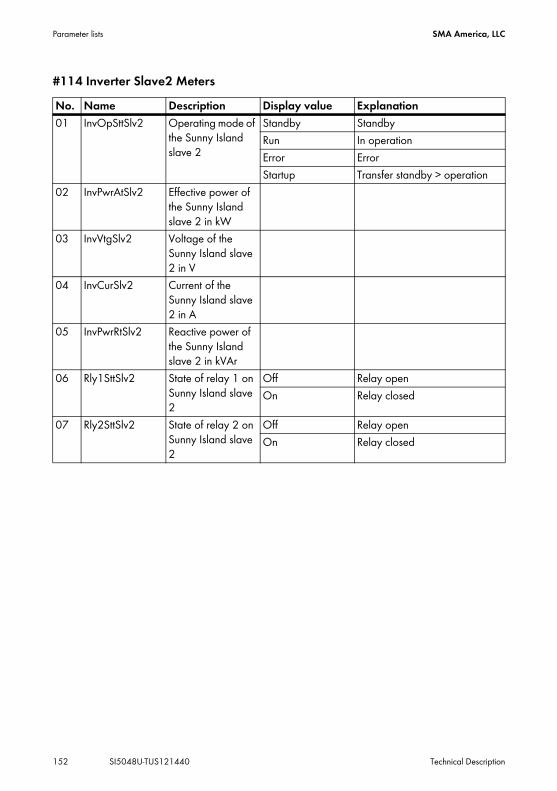
Parameter lists SMA America, LLC
152 SI5048U-TUS121440 Technical Description
#114 Inverter Slave2 MetersNo. Name Description Display value Explanation01 InvOpSttSlv2 Operating mode of
the Sunny Island slave 2
Standby StandbyRun In operationError ErrorStartup Transfer standby > operation
02 InvPwrAtSlv2 Effective power of the Sunny Island slave 2 in kW
03 InvVtgSlv2 Voltage of the Sunny Island slave 2 in V
04 InvCurSlv2 Current of the Sunny Island slave 2 in A
05 InvPwrRtSlv2 Reactive power of the Sunny Island slave 2 in kVAr
06 Rly1SttSlv2 State of relay 1 on Sunny Island slave 2
Off Relay openOn Relay closed
07 Rly2SttSlv2 State of relay 2 on Sunny Island slave 2
Off Relay openOn Relay closed

SMA America, LLC Parameter lists
Technical Description SI5048U-TUS121440 153
#115 Inverter Slave3 MetersNo. Name Description Display value Explanation01 InvOpSttSlv3 Operating mode of
the Sunny Island slave 3
Standby StandbyRun In operationError ErrorStartup Transfer standby > operation
02 InvPwrAtSlv3 Effective power of the Sunny Island slave 3 in kW
03 InvVtgSlv3 Voltage of the Sunny Island slave 3 in V
04 InvCurSlv3 Current of the Sunny Island slave 3 in A
05 InvPwrRtSlv3 Reactive power of the Sunny Island slave 3 in kVAr
06 Rly1SttSlv3 State of relay 1 on Sunny Island slave 3
Off Relay openOn Relay closed
07 Rly2SttSlv3 State of relay 2 on Sunny Island slave 3
Off Relay openOn Relay closed

Parameter lists SMA America, LLC
154 SI5048U-TUS121440 Technical Description
19.1.2 Battery Meters (120#)No. Name Description Display value
Plain text (No.)Explanation
01 BatSoc Present battery charge state (SOC) in %
02 BatVtg Battery voltage in V03 BatChrgVtg Charging voltage
target value in V04 AptTmRmg Remaining
absorption time in hours, minutes and seconds
05 BatChrgOp Active charging process
Boost (1) Boost chargeFull (2) Full chargeFloat (3;7) Float chargeEqualize (4;5) Equalize chargeSilent (6;8) Silent mode (resting phase)
06 TotBatCur Total battery current of the cluster in A
Negative values indicate charging, positive values indicate discharging.
07 BatTmp Battery temperature in °C
08 RmgTmFul Remaining time until next full charge in days
09 RmgTmEqu Remaining time until next equalization charge in days
10 AptPhs Absoption phase state
Off (1) Absorption phase not activeOn (2) Absorption phase is active
11 BatSocErr Estimated SOC error in %
Estimated error of the displayed state of charge from the battery's actual state of charge in percent (e.g. +/-3 %).

SMA America, LLC Parameter lists
Technical Description SI5048U-TUS121440 155
19.1.3 External Meters (130#)#131 Total Meters
132# Grid State
#133 Generator State
No. Name Description01 TotExtPwrAt Total active power of the external source in kW02 TotExtCur Total current of the external source in A03 TotExtPwrRt Total reactive power in kVAr04 TotLodPwr Total averaged active power of the consumers (cluster) in kW05 TotMccLodPwr Total averaged active power of the consumers (Multicluster) in kW
No. Name Description01 GdRmgTm Remaining time of GdValTm parameter in hours, minutes and seconds
No. Name Description Display valuePlain text (No.)
Explanation
01 GnDmdSrc Source for generator request:
None (1) No requestBat (2) Battery charge state-dependentLod (3) Load-dependentTim (4) Time-controlledRun1h (5) Requested for 1 hourStart (6) Manually startedExtSrcReq (7) Requested via an external
source02 GnStt Generator state Off (1) Off
Init (2) InitReady (3) Waiting for request (ready)Warm (4) Warming upConnect (5) ConnectingRun (6) In operationRetry (7) RestartingAC Disconnect (8) DisconnectingCool (9) Cooling downLock (10) Locked after gen operationFail (11) Generator failure or errorFailLock (12) Locked after gen failure

Parameter lists SMA America, LLC
156 SI5048U-TUS121440 Technical Description
#134 Device Meters
135# Slave1 Meters
136# Slave2 Meters
03 GnRmgTm Minimum remaining generator run time. Displayed in hours, minutes and seconds.
04 GnRnStt Generator run state that is detected by Sunny Island master.
Off (1) offOn (2) on
No. Name Description01 ExtPwrAt Active power of the external source in kW02 ExtVtg Voltage of the external source in V03 ExtCur Current of the external source in A04 ExtFrq Frecuency of the external source in Hz05 ExtPwrRt Reactive power of the external source in kVAr
No. Name Description01 ExtPwrAtSlv1 Active power of the external source slave 1 in kW02 ExtVtgSlv1 Voltage of the external source slave 1 in V03 ExtCurSlv1 Current of the external source slave 1 in A04 ExtPwrRtSlv1 Reactive power of the external source slave 1 in kVAr
No. Name Description01 ExtPwrAtSlv2 Active power of the external source slave 2 in kW02 ExtVtgSlv2 Voltage of the external source slave 2 in V03 ExtCurSlv2 Current of the external source slave 2 in A04 ExtPwrRtSlv2 Reactive power of the external source slave 2 in kVAr
No. Name Description Display valuePlain text (No.)
Explanation

SMA America, LLC Parameter lists
Technical Description SI5048U-TUS121440 157
137# Slave3 Meters
138# Chp Meters (Combined Heat and Power)
19.1.4 Charge Controller (140#) (not UL-certified)
141# SIC40 Total
No. Name Description01 ExtPwrAtSlv3 Active power of the external source slave 3 in kW02 ExtVtgSlv3 Voltage of the external source slave 3 in V03 ExtCurSlv3 Current of the external source slave 3 in A04 ExtPwrRtSlv3 Reactive power of the external source slave 3 in kVAr
No. Name Description Display value Explanation01 ChpStt State of CHP plant Idle Off
Run In operationLock Locked after operation
02 ChpPwrAt Power of the CHP plant
03 ChpRmgTm Remaining time of the CHP plant (minimum running time in hours, minutes and seconds)
04 ChpStrRmgTm Remaining time of the power request of the CHP plant (minimum running time in hours, minutes and seconds)
Visibility of parameters in menu 140#The parameters in menu 140# are only visible, if at least one Sunny Island Charger is connected to the system.
No. Name Description01 TotSicEgyCntIn Total energy of all Sunny Island Chargers in kWh02 TotSicDyEgyCntIn Total daily yield of all Sunny Island Chargers in kWh03 TotSicPvPwr Total PV power of all Sunny Island Chargers in W04 TotSicBatCur Total battery current of all Sunny Island Chargers in A

Parameter lists SMA America, LLC
158 SI5048U-TUS121440 Technical Description
142# SIC40 1
143# SIC40 2
144# SIC40 3
No. Name Description01 Sic1EgyCntIn Energy of the first Sunny Island Charger in kWh02 Sic1TdyEgyCntIn Daily yield of the first Sunny Island Charger in kWh03 Sic1PvPwr PV power of the first Sunny Island Charger in W04 Sic1PvVtg PV voltage of the first Sunny Island Charger in V05 Sic1BatVtg Battery voltage of the first Sunny Island Charger in V06 Sic1BatCur Battery current of the first Sunny Island Charger in A07 Sic1HsTmp Heatsink temperature of the first Sunny Island Charger in °C08 Sic1SWVers Software version of the first Sunny Island Charger
No. Name Description01 Sic2EgyCntIn Energy of the second Sunny Island Charger in kWh02 Sic2TdyEgyCntIn Daily yield of the second Sunny Island Charger in kWh03 Sic2PvPwr PV power of the second Sunny Island Charger in W04 Sic2PvVtg PV voltage of the second Sunny Island Charger in V05 Sic2BatVtg Battery voltage of the second Sunny Island Charger in V06 Sic2BatCur Battery current of the second Sunny Island Charger in A07 Sic2HsTmp Heatsink temperature of the second Sunny Island Charger in °C08 Sic2SWVers Software version of the second Sunny Island Charger
No. Name Description01 Sic3EgyCntIn Energy of the third Sunny Island Charger in kWh02 Sic3TdyEgyCntIn Daily yield of the third Sunny Island Charger in kWh03 Sic3PvPwr PV power of the third Sunny Island Charger in W04 Sic3PvVtg PV voltage of the third Sunny Island Charger in V05 Sic3BatVtg Battery voltage of the third Sunny Island Charger in V06 Sic3BatCur Battery current of the third Sunny Island Charger in A07 Sic3HsTmp Heatsink temperature of the third Sunny Island Charger in °C08 Sic3SWVers Software version of the third Sunny Island Charger

SMA America, LLC Parameter lists
Technical Description SI5048U-TUS121440 159
145# SIC40 4
19.2 Adjustable parameters
19.2.1 Inverter Settings (210#)
No. Name Description01 Sic4EgyCntIn Energy of the fourth Sunny Island Charger in kWh02 Sic4TdyEgyCntIn Daily yield of the fourth Sunny Island Charger in kWh03 Sic4PvPwr PV power of the fourth Sunny Island Charger in W04 Sic4PvVtg PV voltage of the fourth Sunny Island Charger in V05 Sic4BatVtg Battery voltage of the fourth Sunny Island Charger in V06 Sic4BatCur Battery current of the fourth Sunny Island Charger in A07 Sic4HsTmp Heatsink temperature of the fourth Sunny Island Charger in °C08 Sic4SWVers Software version of the fourth Sunny Island Charger
No. Name Description Value Explanation Default value
01 InvVtgNom Nominal voltage of the Sunny Island
120 V / 60 Hz 120 V
02 InvChrgCurMax Maximum AC charging current
38 A
03 InvFrqNom Nominal frequency of the Sunny Island
120 V / 60 Hz 60 Hz

Parameter lists SMA America, LLC
160 SI5048U-TUS121440 Technical Description
19.2.2 Battery Settings (220#)#221 Battery PropertyNo. Name Description Value Explanation Default
value01 BatTyp Battery type VRLA Valve regulated lead
acid (AGM or GEL type)
VRLA
FLA Flooded lead acid battery
NiCd Nickel-cadmium battery
02 BatCpyNom Nominal battery capacity(E:C10/U:C20)
100 Ah
03 BatVtgNom Nominal battery voltage
VRLA 48 VFLA 48 VNiCd 45.6 V
04 BatTmpMax Maximum battery temperature
104°F … 122°F (40 °C … 50 °C)
113°F (45 °C)
05 BatTmpStr Battery start temperature following stop due to overtemperature
32 °F ... 104 ° F(0 °C … 40 °C) ”BatTmpMax”
104°F(40 °C)
06 BatWirRes Power resistor of the battery connection in mOhm
0 mOhm …50 mOhm
07 BatFanTmpStr Starting temperature for the ”BatFan” function
104°F (40 °C)

SMA America, LLC Parameter lists
Technical Description SI5048U-TUS121440 161
#222 Battery Charge ModeNo. Name Description Value Explanation Default
value01 BatChrgCurMax Charging current of
the battery10 A … 1200 A 1,200 A
02 AptTmBoost Absorption time for boost charge
1 min … 600 min VRLA 120 min1 min … 600 min FLA 90 min1 min … 600 min NiCd 300 min
03 AptTmFul Absorption time for full charge
1 h … 20 h VRLA 5 h1 h … 20 h FLA 5 h1 h … 20 h NiCd 7 h
04 AptTmEqu Absorption time for equalization charge
1 h … 48 h 10 h
05 CycTmFul Full charge cycle time
1 day ... 180 days 14 days
06 CycTmEqu Equalization charge cycle time
7 days ... 365 days 180 days
07 ChrgVtgBoost Nominal value of cell voltage for normal charge
2.2 V … 2.7 V VRLA 2.40 VFLA 2.55 V
1.5 V ... 1.8 V NiCd 1.65 V08 ChrgVtgFul Nominal value of
cell voltage for full charge
2.3 V ... 2.7 V VRLA 2.40 VFLA 2.50 V
1.5 V ... 1.8 V NiCd 1.65 V09 ChrgVtgEqu Nominal value of
cell voltage for equalization charge
2.3 V ... 2.7 V VRLA 2.40 VFLA 2.50 V
1.5 V ... 1.8 V NiCd 1.65 V
10 ChrgVtgFlo Nominal value of cell voltage for float charge
2.2 V ... 2.4 V VRLA 2.25 VFLA 2.25 V
1.4 V ... 1.6 V NiCd 1.55 V11 BatTmpCps Battery temperature
compensation0 mV /°C ... 10 mV /°C
VRLA 4.0 mV/°C
FLA 4.0 mV/°CNiCd 0 mV/°C
12 AutoEquChrgEna Automatic equalization charge
Disable disable EnableEnable enable

Parameter lists SMA America, LLC
162 SI5048U-TUS121440 Technical Description
#223 Battery Protection
#224 Battery Silent Mode
No. Name Description Display value Default value01 BatPro1TmStr Starting time of the
battery-preservation mode (level 1)
22:00:00
02 BatPro1TmStp End time of battery-preservation mode (level 1)
06:00:00
03 BatPro2TmStr Starting time of the battery-preservation mode (level 2)
17:00:00
04 BatPro2TmStp End time of battery-preservation mode (level 2)
09:00:00
05 BatPro1Soc Battery charge state for battery-preservation mode level 1
0 % … 70 % 20 %
06 BatPro2Soc Battery charge state for battery-preservation mode level 2
0 % … 70 % 15 %
07 BatPro3Soc Battery charge state for battery-preservation mode level 3
0 % … 70 % 10 %
No. Name Description Value Explanation Default value
01 SilentEna Silent mode on the grid
Disable disable DisableEnable enable
02 SilentTmFlo Maximum time for float charge until transfer into silent
1 h … 48 h 3 h
03 SilentTmMax Maximum time for silent until transfer into float charge
1 h … 168 h 12 h

SMA America, LLC Parameter lists
Technical Description SI5048U-TUS121440 163
225# Battery Current Sensor
19.2.3 External Settings (230#)231# Ext General
No. Name Description Value Explanation Default value
01 BatCurSnsTyp Battery current sensor type
None No sensor is connected.
None
60 mV Battery Current Sensor 60 mV
50 mV Battery Current Sensor 50 mV
02 BatCurGain60 External battery current sensor type (60 mV type)
0 A … 1.000 A 100 A/60 mV
03 BatCurGain50 External battery current sensor type (50 mV type)
0 A … 1.000 A 100 A/50 mV
04 BatCurAutoCal Automatic calibration of the external battery current sensor
Start Start the automatic calibration:
No. Name Description Value Explanation Default value
01 PvFeedTmStr PV feed-in start 04:00:0002 PvFeedTmStp PV feed-in stop 22:00:0003 ExtLkTm Lock time after
reverse power or relay protection
0 min … 60 min 20 min
05 ExtSrc Generator and grid operating mode
PvOnly PV only PvOnlyGen GeneratorGrid GridGenGrid Generator / Grid
12 ChpEna Combined heat and power
Disable disabled DisableEnable enabled

Parameter lists SMA America, LLC
164 SI5048U-TUS121440 Technical Description
232# Grid ControlNo. Name Description Display value Explanation Default
value01 GdVtgMin Minimum grid voltage 105.6 V02 GdVtgMax Maximum grid voltage 132 V03 GdCurNom Grid nominal current 30 A04 GdFrqNom Grid nominal frequency 60 Hz05 GdFrqMin Minimum grid frequency 59.3 Hz06 GdFrqMax Maximum grid
frequency60.5 Hz
07 GdVldTm Minimum time required for grid voltage and grid frequency to be within permissible range for connection
300 sec
08 GdMod Grid interface GridCharge Grid charging only GdFeedGridFeed Grid feed and grid
charging09 GdRvPwr Permissible grid reverse
power (active power)0 W … 5000 W 100 W
10 GdRvTm Permissible time for grid reverse power
0 sec … 60 sec 5 sec
15 GdAlSns AI sensitivity Low Low NormalMedium MediumNormal NormalHigh High
37 GdVtgIncProEna Voltage increase protection
Disable disable DisableEnable enable
38 GdVtgIncPro Boundary for voltage increase protection
132 V
41 GdSocEna Activate the grid request based on SOC
Disable disable DisableEnable enable
42 GdPwrEna Activate the grid request based on power
Disable disable DisableEnable enable

SMA America, LLC Parameter lists
Technical Description SI5048U-TUS121440 165
233# Grid StartNo. Name Description Display value Explanation Default
value01 GdSocTm1Str SOC limit for
switching on the grid for time 1
40 %
02 GdSocTm1Stp SOC limit for switching off the grid for time 1
80 %
03 GdSocTm2Str SOC limit for switching on the grid for time 2
40 %
04 GdSocTm2Stp SOC limit for switching off the grid for time 2
80 %
05 GdTm1Str Time 1 for grid request in hours, minutes and seconds.Begin time 1, end time 2.
06 GdTm2Str Time 2 for grid request in hours, minutes and seconds.Begin time 2, end time 1.
07 GdPwrStr Grid request starting capacity
4.0 kW
08 GdPwrStp Grid request disconnection power limit
2.0 kW
09 GdStrChrgMod Charging start upon grid connection
Off Off EqualFull Full chargeEqual Equalize chargeBoth Full and equalization
charge

Parameter lists SMA America, LLC
166 SI5048U-TUS121440 Technical Description
234# Generator ControlNo. Name Description Value Explanation Default
value01 GnVtgMin Minimum generator
voltage80 V
02 GnVtgMax Maximum generator voltage
150 V
03 GnCurNom Nominal generator current
30 A
04 GnFrqNom Generator nominal frequency at nominal load
60 Hz
05 GnFrqMin Minimum generator frequency
54 Hz
06 GnFrqMax Maximum generator frequency
66 Hz
07 GnStrMod Generator interface Manual Manual AutostartAutostart AutomaticGenMan Generator
management box from SMA
08 GnOpTmMin Minimum run time of the generator
15 min
09 GnStpTmMin Minimum stop time of the generator
15 min
10 GnCoolTm Cooling-down time of the generator
5 min
11 GnErrStpTm Stop time of the generator if there is a fault
1 h
12 GnWarmTm Warm-up time 60 sec13 GnRvPwr Generator reverse
power (active power)100 W
14 GnRvTm Permissible time for reverse power/reverse current
30 sec
15 GnCtlMod Generator regulation Cur Current CurCurFrq Frequency

SMA America, LLC Parameter lists
Technical Description SI5048U-TUS121440 167
235# Generator Start
20 GnAlSns AI sensitivity Low Low NormalMedium MediumNormal NormalHigh High
No. Name Description Value Explanation Default value
01 GnAutoEna Generator autostart Off Disable OnOn Enable
02 GnAutoStr Number of autostarts 303 GnSocTm1Str SOC limit for switching on
generator for time 140 %
04 GnSocTm1Stp SOC limit for switching off generator for time 1
80 %
05 GnSocTm2Str SOC limit for switching on generator for time 2
40 %
06 GnSocTm2Stp SOC limit for switching off generator for time 2
80 %
07 GnTm1Str Time 1 for generator request in hours, minutes and seconds.Begin: Time 1, End: Time 2
08 GnTm2Str Time 2 for generator request in hours, minutes and seconds.Begin: Time 2, End: Time 1
09 GnPwrEna Generator request based on power
Off Disable OffOn Enable
10 GnPwrStr Generator request switch-on power limit
4 kW
11 GnPwrStp Generator request switch-off power limit
2 kW
12 GnPwrAvgTm Average time for power-related generator start
60 sec
13 GnTmOpEna Time-controlled generator operation
Disable Disable DisableEnable Enable
No. Name Description Value Explanation Default value
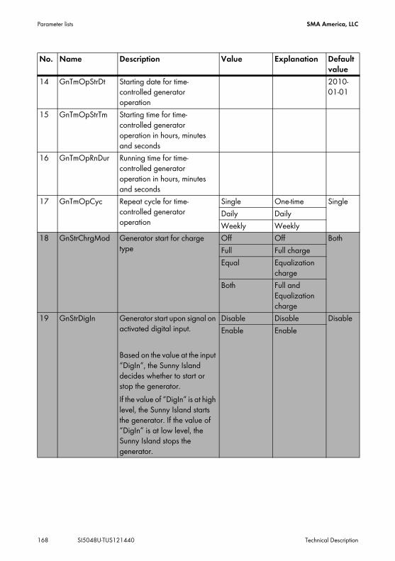
Parameter lists SMA America, LLC
168 SI5048U-TUS121440 Technical Description
14 GnTmOpStrDt Starting date for time-controlled generator operation
2010-01-01
15 GnTmOpStrTm Starting time for time-controlled generator operation in hours, minutes and seconds
16 GnTmOpRnDur Running time for time-controlled generator operation in hours, minutes and seconds
17 GnTmOpCyc Repeat cycle for time-controlled generator operation
Single One-time SingleDaily DailyWeekly Weekly
18 GnStrChrgMod Generator start for charge type
Off Off BothFull Full chargeEqual Equalization
chargeBoth Full and
Equalization charge
19 GnStrDigIn Generator start upon signal on activated digital input.
Based on the value at the input “DigIn”, the Sunny Island decides whether to start or stop the generator.If the value of “DigIn” is at high level, the Sunny Island starts the generator. If the value of “DigIn” is at low level, the Sunny Island stops the generator.
Disable Disable DisableEnable Enable
No. Name Description Value Explanation Default value

SMA America, LLC Parameter lists
Technical Description SI5048U-TUS121440 169
236# CHP Control (Combined Heat and Power)
237# CHP Start
No. Name Description Value Explanation Default value
01 ChpOpTmMin Minimum run time of CHP plant
60 min
02 ChpStpTmMin Minimum stop time of CHP plant
10 min
03 ChpPwrMax Maximum power of CHP plant
5 kW
04 ChpPwrMin Minimum power of CHP plant
2 kW
05 ChpFrqPwrMax Maximum frequency of CHP plant
51 Hz
06 ChpFrqPwrMin Minimum frequency of CHP plant
52 Hz
07 ChpFrqOff 53 Hz
No. Name Description Display value Explanation Default value
01 ChpSocTm1Str SOC limit for switching on CHP plant for time 1
40 %
02 ChpSocTm1Stp SOC limit for switching off CHP plant for time 1
80 %
03 ChpSocTm2Str SOC limit for switching on CHP plant for time 2
40 %
04 ChpSocTm2Stp SOC limit for switching off CHP plant for time 2
80 %
05 ChpTm1Str Time 1 for CHP plant request in hours, minutes and seconds.Begin: Time 1, End: Time 2.

Parameter lists SMA America, LLC
170 SI5048U-TUS121440 Technical Description
06 ChpTm2Str Time 2 for CHP plant request in hours, minutes and seconds.Begin: Time 2, End: Time 1.
07 ChpPwrEna Activate CHP plant request based on power
Disable Disable EnableEnable Enable
08 ChpPwrStr Combined heat and power system request switch-on power limit
4 kW
09 ChpPwrStrDly Time delay for power request for CHP plant
5 min
10 ChpManStr AutoStartStop
11 ChpAddOnTm Time for the additional CHP request activated
60 sec
12 ChpAddOffTm Time for the additional CHP request deactivated
120 sec
13 ChpAddSocDel Distance to the next SOC limit
5 %
No. Name Description Display value Explanation Default value

SMA America, LLC Parameter lists
Technical Description SI5048U-TUS121440 171
19.2.4 Relay Settings (240#)241# Relay GeneralNo. Name Description Value Explanation Default
value01 Rly1Op Function of relay 1 Off Off AutoGn
On OnAutoGn Generator requestAutoLodExt External
loadsheddingAutoLod1Soc SOC1 LoadsheddingAutoLod2Soc SOC2 LoadsheddingTmr1 Timer 1Tmr2 Timer 2AptPhs Absorption phaseGnRn Generator in
operationExtVfOk External source
(voltage and frequency OK)
GdOn Grid in operation (connected)
Error ErrorWarn WarningRun In operationBatFan Battery ventilation
(room)AcdCir Acid circulationMccBatFan Multicluster battery
room ventilatorMccAutoLod LoadsheddingCHPReq CHP plant requestCHPAdd CHP plant additional
requestSiComRemote SI Com moduleOverload Overload

Parameter lists SMA America, LLC
172 SI5048U-TUS121440 Technical Description
02 Rly2Op Function of relay 2 Off Off AutoLodExtOn On
AutoGn Generator requestAutoLodExt External
loadsheddingAutoLod1Soc SOC1 LoadsheddingAutoLod2Soc SOC2 LoadsheddingTmr1 Timer 1Tmr2 Timer 2AptPhs Absorption phaseGnRn Generator in
operationExtVfOk External source
(voltage and frequency OK)
GdOn Grid in operation (connected)
Error ErrorWarn WarningRun In operationBatFan Battery ventilation
(room)AcdCir Acid circulationMccBatFan Multicluster battery
room ventilatorMccAutoLod LoadsheddingCHPReq CHP plant requestCHPAdd CHP plant additional
requestSiComRemote SI Com moduleOverload Overload
No. Name Description Value Explanation Default value
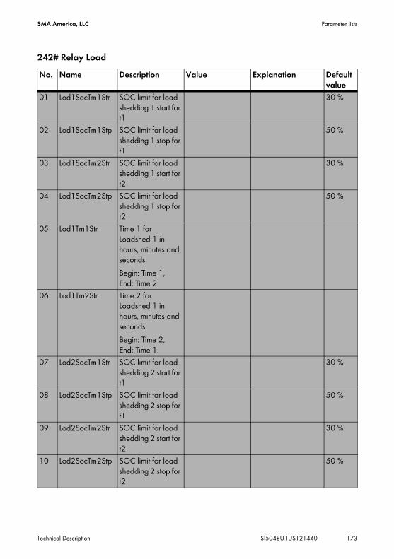
SMA America, LLC Parameter lists
Technical Description SI5048U-TUS121440 173
242# Relay LoadNo. Name Description Value Explanation Default
value01 Lod1SocTm1Str SOC limit for load
shedding 1 start for t1
30 %
02 Lod1SocTm1Stp SOC limit for load shedding 1 stop for t1
50 %
03 Lod1SocTm2Str SOC limit for load shedding 1 start for t2
30 %
04 Lod1SocTm2Stp SOC limit for load shedding 1 stop for t2
50 %
05 Lod1Tm1Str Time 1 for Loadshed 1 in hours, minutes and seconds.Begin: Time 1, End: Time 2.
06 Lod1Tm2Str Time 2 for Loadshed 1 in hours, minutes and seconds.Begin: Time 2, End: Time 1.
07 Lod2SocTm1Str SOC limit for load shedding 2 start for t1
30 %
08 Lod2SocTm1Stp SOC limit for load shedding 2 stop for t1
50 %
09 Lod2SocTm2Str SOC limit for load shedding 2 start for t2
30 %
10 Lod2SocTm2Stp SOC limit for load shedding 2 stop for t2
50 %

Parameter lists SMA America, LLC
174 SI5048U-TUS121440 Technical Description
243# Relay Timer
11 Lod2Tm1Str Time 1 for Loadshed 2 in hours, minutes and seconds.Begin: Time 1, End: Time 2.
12 Lod2Tm2Str Time 2 for Loadshed 2 in hours, minutes and seconds.Begin: Time 2, End: Time 1.
No. Name Description Display value Explanation Default value
01 RlyTmr1StrDt Start date for timer 1
2006-01-01
02 RlyTmr1StrTm Start time for relay control timer 1 in hours, minutes and seconds.
03 RlyTmr1Dur Running time for relay control timer 1 in hours, minutes and seconds.
04 RlyTmr1Cyc Repetition cycle time for timer 1
Single One-time SingleDaily DailyWeekly Weekly
05 RlyTmr2StrDt Start date timer 2 2006-01-01
06 RlyTmr2StrTm Start time for relay control timer 2 in hours, minutes and seconds.
07 RlyTmr2Dur Running time for relay control timer 2 in hours, minutes and seconds.
No. Name Description Value Explanation Default value

SMA America, LLC Parameter lists
Technical Description SI5048U-TUS121440 175
244# Relay Slave1
08 RlyTmr2Cyc Repetition cycle time for timer 2
Single One-time SingleDaily DailyWeekly Weekly
No. Name Description Value Explanation Default value
01 Rly1OpSlv1 Function of relay 1 on slave 1
Off Off OffOn OnAutoGn Generator requestAutoLodExt External
loadsheddingAutoLod1Soc SOC1 LoadsheddingAutoLod2Soc SOC2 LoadsheddingTmr1 Timer 1Tmr2 Timer 2AptPhs Absorption phaseGnRn Generator in
operationExtVfOk External source
(voltage and frequency OK)
GdOn Grid in operation (connected)
Error ErrorWarn WarningRun In operationBatFan Battery ventilation
(room)AcdCir Acid circulationMccBatFan Multicluster battery
room ventilatorMccAutoLod LoadsheddingCHPReq CHP plant requestCHPAdd CHP plant additional
requestSiComRemote SI Com moduleOverload Overload
No. Name Description Display value Explanation Default value

Parameter lists SMA America, LLC
176 SI5048U-TUS121440 Technical Description
02 Rly2OpSlv1 Function of relay 2 on slave 1
Off Off OffOn OnAutoGn Generator requestAutoLodExt External
loadsheddingAutoLod1Soc SOC1 LoadsheddingAutoLod2Soc SOC2 LoadsheddingTmr1 Timer 1Tmr2 Timer 2AptPhs Absorption phaseGnRn Generator in
operationExtVfOk External source
(voltage and frequency OK)
GdOn Grid in operation (connected)
Error ErrorWarn WarningRun In operationBatFan Battery ventilation
(room)AcdCir Acid circulationMccBatFan Multicluster battery
room ventilatorMccAutoLod LoadsheddingCHPReq CHP plant requestCHPAdd CHP pland additional
requestSiComRemote SI Com moduleOverload Overload
No. Name Description Value Explanation Default value

SMA America, LLC Parameter lists
Technical Description SI5048U-TUS121440 177
245# Relay Slave2No. Name Description Value Explanation Default
value01 Rly1OpSlv2 Function of relay 1
on slave 2Off Off OffOn OnAutoGn Generator requestAutoLodExt External
loadsheddingAutoLod1Soc SOC1 LoadsheddingAutoLod2Soc SOC2 LoadsheddingTmr1 Timer 1Tmr2 Timer 2AptPhs Absorption phaseGnRn Generator in
operationExtVfOk External source
(voltage and frequency OK)
GdOn Grid in operation (connected)
Error ErrorWarn WarningRun In operationBatFan Battery ventilation
(room)AcdCir Acid circulationMccBatFan Multicluster battery
room ventilatorMccAutoLod LoadsheddingCHPReq CHP plant requestCHPAdd CHP pland additional
requestSiComRemote SI Com moduleOverload Overload

Parameter lists SMA America, LLC
178 SI5048U-TUS121440 Technical Description
02 Rly2OpSlv2 Function of relay 2 on slave 2
Off Off OffOn OnAutoGn Generator requestAutoLodExt External
loadsheddingAutoLod1Soc SOC1 LoadsheddingAutoLod2Soc SOC2 LoadsheddingTmr1 Timer 1Tmr2 Timer 2AptPhs Absorption phaseGnRn Generator in
operationExtVfOk External source
(voltage and frequency OK)
GdOn Grid in operation (connected)
Error ErrorWarn WarningRun In operationBatFan Battery ventilation
(room)AcdCir Acid circulationMccBatFan Multicluster battery
room ventilatorMccAutoLod LoadsheddingCHPReq CHP plant requestCHPAdd CHP pland additional
requestSiComRemote SI Com moduleOverload Overload
No. Name Description Value Explanation Default value
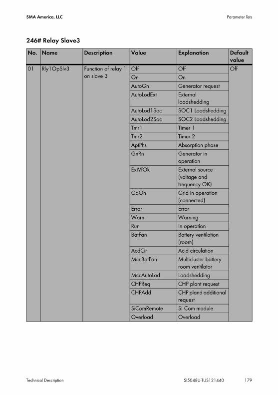
SMA America, LLC Parameter lists
Technical Description SI5048U-TUS121440 179
246# Relay Slave3No. Name Description Value Explanation Default
value01 Rly1OpSlv3 Function of relay 1
on slave 3Off Off OffOn OnAutoGn Generator requestAutoLodExt External
loadsheddingAutoLod1Soc SOC1 LoadsheddingAutoLod2Soc SOC2 LoadsheddingTmr1 Timer 1Tmr2 Timer 2AptPhs Absorption phaseGnRn Generator in
operationExtVfOk External source
(voltage and frequency OK)
GdOn Grid in operation (connected)
Error ErrorWarn WarningRun In operationBatFan Battery ventilation
(room)AcdCir Acid circulationMccBatFan Multicluster battery
room ventilatorMccAutoLod LoadsheddingCHPReq CHP plant requestCHPAdd CHP pland additional
requestSiComRemote SI Com moduleOverload Overload

Parameter lists SMA America, LLC
180 SI5048U-TUS121440 Technical Description
02 Rly2OpSlv3 Function of relay 2 on slave 3
Off Off OffOn OnAutoGn Generator requestAutoLodExt External
loadsheddingAutoLod1Soc SOC1 LoadsheddingAutoLod2Soc SOC2 LoadsheddingTmr1 Timer 1Tmr2 Timer 2AptPhs Absorption phaseGnRn Generator in
operationExtVfOk External source
(voltage and frequency OK)
GdOn Grid in operation (connected)
Error ErrorWarn WarningRun In operationBatFan Battery ventilation
(room)AcdCir Acid circulationMccBatFan Multicluster battery
room ventilatorMccAutoLod LoadsheddingCHPReq CHP plant requestCHPAdd CHP pland additional
requestSiComRemote SI Com moduleOverload Overload
No. Name Description Value Explanation Default value

SMA America, LLC Parameter lists
Technical Description SI5048U-TUS121440 181
19.2.5 System Settings (250#)No. Name Description Value Explanation Default
value01 AutoStr Autostart
If the value 0 has been set, this means that the autostart is deactivated.
3
02 Dt Date MM/DD/YYYY 99.99.9999
03 Tm Time in hours, minutes and seconds
HH:MM:SS 99:99:99
04 BeepEna Button Sound Off Disable OnOn Enable
05 ClstCfg Cluster configuration
Slave1 Cluster Slave 1 1Phase1Slave2 Cluster Slave 2Slave3 Cluster Slave 31Phase1 Single-phase,
1 Sunny Island1Phase2 Single-phase,
2 Sunny Island inverters
1Phase3 Single-phase, 3 Sunny Island inverters
1Phase4 Single-phase, 4 Sunny Island inverters
2Phase2 2-phase, 2 Sunny Island inverters
2Phase4 2-phase, 4 Sunny Island inverters
3Phase 3-phase, 3 Sunny Island inverters
MC‒Box Setting for Multicluster operation

Parameter lists SMA America, LLC
182 SI5048U-TUS121440 Technical Description
06 ComBaud Baudrate 1200 12004800960019200
09 ComAdr Address for communication
1
10 SleepEna Sleep Mode Disable Disable EnableEnable Enable
11 AfraEna Tertiary regulation (AFC - automatic frequency control)
Disable Disable EnableEnable Enable
13 SlpAtNgt Switch off the slaves at night
Disable Disable DisableEnable Enable
14 SlpStrTm Start time for switching off at night (sleep mode)
20:00:00
15 SlpStpTm Stop time for switching off at night (sleep mode)
05:00:00
23 Box Type of Multicluster Box used
MCB-12U MC-Box-12
24 ClstMod Cluster type in Multicluster operation (system configuration)
SingleCluster SingleClusterMainCluster
ExtensionClst1ExtensionClst2ExtensionClst3ExtensionClstN
25 ClstAdr Cluster address28 ChrgCtlOp Typ of DC charging
deviceAuto Automatic AutoDCOnly Battery charger onlySMA Sunny Island Charger
30 RnMod ”Run mode”Reaction in case of failures
RunAlways Always available RunAlwaysStopAlways Stop in case of device
failure
No. Name Description Value Explanation Default value

SMA America, LLC Parameter lists
Technical Description SI5048U-TUS121440 183
19.2.6 Password Setting (280#)For detailed information about this menu see section 10.5 ”Entering the Installer Password” (page 85).
19.3 Diagnosis (300#)
19.3.1 Inverter Diagnosis (310#)311# System Total Diagnosis
312# Inverter Device Diagnosis
No. Name Description01 EgyCntIn Energy absorbed in kWh02 EgyCntOut Energy fed in kWh03 EgyCntTm Energy metering run time in hours
No. Name Description ValuePlain text (No.)
Explanation Default value
01 Adr Device address Master (1) Address MasterSlave1 (2) AddressSlave2 (3) AddressSlave3 (4) Address
02 FwVer Firmware version of the Sunny Island master
03 SN Serial number of the Sunny Island master
04 OnTmh Operating hours of the Sunny Island in hours
05 ClstCfgAt Set cluster configurationThe value is based on the setting in QCG
06 OpStt Operating mode of the Sunny Island
Operating (1) In operationWarning (2) WarningFailure (3) Error

Parameter lists SMA America, LLC
184 SI5048U-TUS121440 Technical Description
313# Inverter Slave1 Diagnosis
07 CardStt SD card status message
Off (1) None OffOperational (2) BusyMount (3) InitializationOutOfSpace (4) No storage space
availableBadFileSys (5) No filing system
recognizedIncomp (6) Incompatible filing
systemParameters (7) Parameter set write
accessParamFailed (8) Parameter set write
access failedWriteLogData (9) Log data write accessWriteLogFailed (10)
Log data write access failed
08 FwVer2 DSP firmware version
09 FwVer3 BFR boot loader10 FwVer4 DSP boot loader
No. Name Description Value Explanation01 FwVerSlv1 Firmware version of
the Sunny Island slave 1
02 SNSlv1 Serial number of the Sunny Island slave 1
03 OnTmhSlv1 Operating hours of the Sunny Island slave 1 in hours
04 PhSlv1 Phase of the Sunny Island slave 1
L1 Phase L1L2 Phase L2L3 Phase L3
05 OpSttSlv1 Operating mode of the Sunny Island slave 1
Operating In operationWarning WarningFailure Error
No. Name Description ValuePlain text (No.)
Explanation Default value

SMA America, LLC Parameter lists
Technical Description SI5048U-TUS121440 185
314# Inverter Slave2 Diagnosis
06 FwVer2Slv1 Firmware version of the Sunny Island slave 1
07 FwVer3Slv1 Bootloader BFR of Sunny Island slave 1
08 FwVer4Slv1 Bootloader DSP of Sunny Island slave 1
No. Name Description Value Explanation01 FwVerSlv2 Firmware version of
the Sunny Island slave 2
02 SNSlv2 Serial number of the Sunny Island slave 2
03 OnTmhSlv2 Operating hours of the Sunny Island slave 2 in hours
04 PhSlv2 Phase of the Sunny Island slave 2
L1 Phase L1L2 Phase L2L3 Phase L3
05 OpSttSlv2 Operating mode of the Sunny Island slave 2
Operating In operationWarning WarningFailure Error
06 FwVer2Slv2 Firmware version of the Sunny Island slave 1
07 FwVer3Slv2 Bootloader BFR of Sunny Island slave 2
08 FwVer4Slv2 Bootloader DSP of Sunny Island slave 2
No. Name Description Value Explanation

Parameter lists SMA America, LLC
186 SI5048U-TUS121440 Technical Description
315# Inverter Slave3 Diagnosis
19.3.2 Battery Diagnosis (320#)
No. Name Description Display value Explanation01 FwVerSlv3 Firmware version of
the Sunny Island slave 3
02 SNSlv3 Serial number of the Sunny Island slave 3
03 OnTmhSlv3 Operating hours of the Sunny Island slave 3 in hours
04 PhSlv3 Phase of the Sunny Island slave 3
L1 Phase L1L2 Phase L2L3 Phase L3
05 OpSttSlv3 Operating mode of the Sunny Island slave 3
Operating In operationWarning WarningFailure Error
06 FwVer2Slv3 Firmware version of the Sunny Island slave 3
07 FwVer3Slv3 Bootloader BFR of Sunny Island slave 3
08 FwVer4Slv3 Bootloader DSP of Sunny Island slave 3
No. Name Description Display value Explanation Default value
01 Soh State of Health (SOH)Ratio of current capacity to its nominal value
100 %
02 StatTm Statistics metering run time in days
03 ChrgFact Charging factor 1.00

SMA America, LLC Parameter lists
Technical Description SI5048U-TUS121440 187
04 BatEgyCntIn Energy meter for battery charge in kWh
05 BatEgyCntOut Energy meter for battery discharge in kWh
06 AhCntIn Meter for battery charging ampere hours
07 AhCntOut Meter for battery discharging ampere hours
08 BatTmpPkMin Minimum battery temperature in °C
09 BatTmpPkMax Maximum battery temperature in °C
10 EquChrgCnt Equalization charge meter
11 FulChrgCnt Full charge meter12 BatCurOfsErr Offset error of
battery current in A13 OcvPointCnt Meter for open-
circuit voltage points
15 AhCntFul Meter for battery discharging ampere hours since the last full charge (in Ah/100 Ah)
16 AhCntEqu Meter for battery discharging ampere hours since the last equalization charge (in Ah/100 Ah)
17 BatVtgPk Maximum battery voltage to have appeared in V
No. Name Description Display value Explanation Default value

Parameter lists SMA America, LLC
188 SI5048U-TUS121440 Technical Description
18 BatCurPkIn Maximum battery current in the charging direction to have appeared (in A)
19 BatCurPkOut Maximum battery current in discharging direction to have appeared (in A)
20 SocHgm100 Frequency distribution of the charge state, in percent, 100 % > SOC >= 90 %
21 SocHgm090 Frequency distribution of the charge state, in percent, 90 % > SOC >= 80 %
22 SocHgm080 Frequency distribution of the charge state, in percent, 80 % > SOC >= 70 %
23 SocHgm070 Frequency distribution of the charge state, in percent, 70 % > SOC >= 60 %
24 SocHgm060 Frequency distribution of the charge state, in percent, 60 % > SOC >= 50 %
25 SocHgm050 Frequency distribution of the charge state, in percent, 50 % > SOC >= 40 %
No. Name Description Display value Explanation Default value

SMA America, LLC Parameter lists
Technical Description SI5048U-TUS121440 189
26 SocHgm040 Frequency distribution of the charge state, in percent, 40 % > SOC >= 30 %
27 SocHgm030 Frequency distribution of the charge state, in percent, 30 % > SOC >= 20 %
28 SocHgm020 Frequency distribution of the charge state, in percent, 20 % > SOC >= 10 %
29 SocHgm010 Frequency distribution of the charge state, in percent, 10 % > SOC >= 0 %
30 SocHgm000 Frequency distribution of the charge state, in percent, SOC < 0 %
31 SocVtgCal Charge state recalibration only via open-circuit voltage (in percent)
32 ErrSocVtgCal Estimated error of the voltage-calibrated charge state
50 %
33 SocChrgCal Charge state recalibration only via full charge
50 %
34 ErrSocChrgCal Estimated error of the full-charge-calibrated charge state
50 %
No. Name Description Display value Explanation Default value

Parameter lists SMA America, LLC
190 SI5048U-TUS121440 Technical Description
19.3.3 External Diagnosis (330#)331# Grid Diagnosis
332# Generator Diagnosis
19.4 Events, Warnings and Failures (History)
19.4.1 Failure / Event (400#)You can find further information about the menus ”410# Failures Current”, ”420# Failure History” and ”430# Event History” starting on section 10.9 ”Display of Warnings and Failures” (page 91).
35 OcvGra Slope of the open-circuit voltage curve
700 Ah/V
36 OcvMax Maximum open-circuit voltage
2.12 V
No. Name Description01 GdEgyCntIn Energy meter for grid feed-in in kWh02 GdEgyCntOut Energy meter for power taken from the grid in kWh03 GdEgyTmh Running time of grid energy meter in hours04 GdOpTmh Operating hour meter for grid operation05 GdCtcCnt Meter for grid connections06 TotTmh Feed-in hours
No. Name Description01 GnEgyCnt Generator energy meter in kWh02 GnEgyTm Running time of generator energy meter in hours03 GnOpTmh Operating hour meter for generator04 GnStrCnt Number of generator starts
No. Name Description Display value Explanation Default value

SMA America, LLC Parameter lists
Technical Description SI5048U-TUS121440 191
19.5 Functions in Operation
19.5.1 Operation (500#)#510 Operation InverterNo. Name Description Value Explanation Default
value01 InvRs Triggering a new
start of the Sunny Island
Restart Restart
02 InvRmOpEna Time-controlled inverter operation
Disable Disable DisableEnable Enable
03 InvTmOpStrDt Start date for time-controlled inverter operation
2006-01-01
04 InvTmOpStrTm Start time for time-controlled inverter operation in hours, minutes and seconds
Value can be set freely
05 InvTmOpRnDur Running time for time-controlled inverter operation in hours, minutes and seconds
Value can be set freely
06 InvTmOpCyc Repetition cycle for time-controlled inverter operation (Tm1)
Single One-time SingleDaily DailyWeekly Weekly

Parameter lists SMA America, LLC
192 SI5048U-TUS121440 Technical Description
520# Operation Battery
07 CntRs Erase energy counterThe value indicates which energy counters should be erased.
Inv Sunny IslandBat BatteryGn GeneratorGd GridAll All energy metersSic1 Sunny Island
Charger 1Sic2 Sunny Island
Charger 2Sic3 Sunny Island
Charger 3Sic4 Sunny Island Charger
4SicAll All Sunny Island
Chargers08 TstClstCom Activates the
communication test between the individual clusters:
Off OffTransmit Enable
09 ClstComStt Communication test status
Wait WaitOK Completed
10 FrcClstUpd Manual update of the cluster
UpdateClst Cluster Update (BFR & DSP)
UpdateClstBFR Cluster Update (BFR)UpdateClstDSP Cluster Update (DSP)
No. Name Description Display value Explanation Default value
01 ChrgSelMan Manual Equalization Charge
Idle Wait IdleStart StartStop Stop
No. Name Description Value Explanation Default value

SMA America, LLC Parameter lists
Technical Description SI5048U-TUS121440 193
#540 Operation Generator
550# Operation MMC
560# Operation GridThe 560# Operation Grid menu can only be seen if the external voltage source of the Sunny Island is set to ”Grid” or ”GenGrid”.
No. Name Description Value Explanation Default value
01 GnManStr Manual generator start
Auto Automatic AutoStop StopStart StartRun1h Run for 1 h
02 GnAck Error confirmation for generator fault
Ackn Failure confirmation
No. Name Description Value Explanation Default value
01 ParaSto Save parameter settings
Set1 Parameter Set1Set2 Parameter Set2
02 ParaLod Load parameter settings
Set1 Parameter Set1Set2 Parameter Set2Factory Load factory settings
03 CardFunc Functions of the SD card
ForcedWrite Forced writingStoEvtHis Save event memoryStoFailHis Save error memoryStoHis Save event and error
memory04 DatLogEna Automatic data
storageOff Disable OnOn Enable
No. Name Description Value Explanation Default value
01 GdManStr Manual grid start Auto Automatic AutoStop StopStart Start

Parameter lists SMA America, LLC
194 SI5048U-TUS121440 Technical Description
19.6 Direct Access to the Parameters
19.6.1 Direct Access (600#)Direct access to parameters is explained in detail in section 10.3 ”Direct Access (to the parameters)” (page 81).

SMA America, LLC Troubleshooting
Technical Description SI5048U-TUS121440 195
20 TroubleshootingIn general the Sunny Island distinguishes between events and errors.
• Events describe state changes or transient states (e.g. generator connection).• Failures describe states that are not permitted or are only permitted up to a certain rate. This
includes warnings, failures and errors. A user interaction is generally required.
20.1 Failure ConfirmationIf there is a disturbance or failure, the Sunny Island goes into standby.Proceed as follows to confirm a failure:1. Remove the cause.2. Confirm failure with <ENTER>.3. Start the Sunny Island again.
20.2 Autostart HandlingThe Sunny Island has an autostart counter which counts down by 1 with every automatic start. After 10 minutes of normal operation of the Sunny Island, the autostart counter is set back to its original value.If another failure occurs when the autostart counter is at 0, the Sunny Island waits for 10 minutes and then attempts to restart. The autostart counter begins to run again.The number of the autostarts allowed can be set using the ”250.01 AutoStr” parameter (in standby mode).
20.3 Master Slave HandlingEach device detects the failures separately and saves it. The slaves transfer their failures to the master. The master collects these failure messages and enters the slave failures as warnings into its history.Example:Slave 1 has detected overtemperature. It enters this failure in its history and reports it to the master, which also enters it as a warning into its failure history (”Menu 420# Failure History”).The following message appears in the lower line on the master.
If warning 138 is still active on slave 1, the Enter symbol is displayed at the end of the line.After confirmation on the master using ENTER, the warning is forwarded to the corresponding slave.

Troubleshooting SMA America, LLC
196 SI5048U-TUS121440 Technical Description
The master shows the following message after confirmation.
20.4 Handling Pending Failures During the Booting ProcedureDuring the booting procedure, all pending failures are generally confirmed without an entry being made in the history. This way, after the booting procedure failure that is still pending will be re-entered, or if the system detects that this failure has stopped, it is entered as no longer being present.
20.5 Display of Failures and EventsEach failure and each event have a unique three-digit display number that is created according to the parameter/measuring value assignment. The events and failures have the identical numerical range:
• 1xx - INV - Inverter• 2xx - BAT - Battery• 3xx - EXT - Extern• 4xx - GEN - Generator• 5xx - GRD - Grid• 6xx - RLY - Relay• 7xx - SYS - System• 8xx - AUX - external devices and components
No Comparison between Master and SlaveThe failure and event memory are not compared between the master and slaves. When the Sunny Island system starts anew the failures in the slave devices are confirmed.
Meaning of the abbreviations”F” marks a failure, ”W” marks a warning and ”E” marks an event.In the event of a failure, and provided it is recorded, ”!” is displayed for a failure that has occurred and ”C” is displayed for a failure that has stopped.

SMA America, LLC Troubleshooting
Technical Description SI5048U-TUS121440 197
20.6 EventsThe meanings of the events displayed by the Sunny Island are described in the following table:
20.6.1 Category INV
20.6.2 Category BAT
Display no. DescriptionE101 Wait statusE102 Startup processE103 In operationE104 Operating on the generator (at external input)E105 Operating on the grid (at external input)E106 Feed-in grid operation (at external input)E107 Sleep mode (slave in single-phase systems)E108 Silent mode on the gridE110 Shutting down due to faultE115 Emergency chargeE118 Automatic startE119 Manual start (transition from standby mode to operation)E120 Manual stop (transition from operation to standby)E129 External start (remote)E130 External stop (remote)E131 AFC StartE132 AFC Stop
Display no. DescriptionE202 (Partial) reset of BMS due to new batteryE203 State change, battery charging algorithm for float chargeE204 State change, battery charging algorithm for boost chargeE205 State change, battery charging algorithm for full chargeE206 State change into silent mode optionE207 State change, battery charging algorithm for equalization chargeE221 Status change Battery preservation mode level 1E222 Status change Battery preservation mode level 2E223 Status change Battery preservation mode level 3

Troubleshooting SMA America, LLC
198 SI5048U-TUS121440 Technical Description
20.6.3 Category GEN
20.6.4 GRD Category
Display no. DescriptionE401 Automatic generator start due to set criteria
(battery charge state, power, time, etc.)E402 Automatic generator stop due to set criteria
(battery charge state, power, time, etc.)E403 Manual generator startE404 Manual generator stopE405 Manual error confirmation of generator faultE406 Generator Request
Display no. DescriptionE501 Grid request due to SOC (goes below limit)E502 Release of grid due to SOC (exceeds)E503 Grid request due to exceeding the power limitE504 Grid release due to going below the power limitE505 Manual grid requestE506 Manual grid releaseE507 Grid feeding startsE508 Grid feeding stops

SMA America, LLC Troubleshooting
Technical Description SI5048U-TUS121440 199
20.6.5 Category RELDisplay no. DescriptionE601 Relay 1 offE602 Relay 1 onE603 Relay 1 on slave 1 offE604 Relay 1 on slave 1 onE605 Relay 1 on slave 2 offE606 Relay 1 on slave 2 onE607 Relay 1 on slave 3 offE608 Relay 1 on slave 3 onE609 Transfer relay openE610 Transfer relay closedE611 Transfer relay on slave 1 openE612 Transfer relay on slave 1 closedE613 Transfer relay on slave 2 openE614 Transfer relay on slave 2 closedE615 Transfer relay on slave 3 openE616 Transfer relay on slave 3 closedE617 Relay 2 openE618 Relay 2 closedE619 Relay 2 on slave 1 openE620 Relay 2 on slave 1 closedE621 Relay 2 on slave 2 openE622 Relay 2 on slave 2 closedE623 Relay 2 on slave 3 openE624 Relay 2 on slave 3 closedE625 Digital input OFF (Low)E626 Digital input ON (High)E629 Digital input slave 2 to OFF (low)E630 Digital input slave 2 to ON (high)E631 Digital input slave 3 to OFF (low)E632 Digital input slave 3 to ON (high)

Troubleshooting SMA America, LLC
200 SI5048U-TUS121440 Technical Description
20.6.6 Category SYS
20.7 Failure CategoriesThe Sunny Island distinguishes between five different levels of failures, each requiring different user interaction:
Display no. DescriptionE705 Device startE706 Date, time changedE707 New system configured in QCGE708 Part 1 of the firmware updatedE709 Part 2 of the firmware updatedE710 Cluster firmware updatedE711 MMC/SD card insertedE712 Parameters from MMC/SD card loadedE851 Sunny Island Charger #1 detectedE852 Sunny Island Charger #2 detectedE853 Sunny Island Charger #3 detectedE854 Sunny Island Charger #4 detected
Level Designation Display Meaning1 Warning Warning Warning, device continues to run. There is an explicit
information on the Home Screen that a warning was recorded.
2 Fault 1 Malfunction Failure that can only be detected during operation. Device switches off. Device can be restarted immediately (autostart).
3 Fault 2 Malfunction Failure that can also be detected in standby mode. Device switches off. The device can only be restarted (autostart) after the system detects that the failure has stopped.
4 Failure Failure Device fault. Device switches off. User interaction required (troubleshooting, confirmation, manual restart).
5 Device Failure Defect Device is defect. Device switches off and does not switch on again. Permanent disable. Device must be replaced.

SMA America, LLC Troubleshooting
Technical Description SI5048U-TUS121440 201
20.8 Warnings and Failure MessagesThe meanings of the failures and warnings displayed by the Sunny Island are described in the following table:
20.8.1 Category INVDisplay no. Level DescriptionF109 3 Transformer overtemperatureW110 1 Overtemperature on transformer on slave 1W111 1 Overtemperature on transformer on slave 2W112 1 Overtemperature on transformer on slave 3F113 3 Overtemperature on heatsinkW114 1 Overtemperature on heatsink on slave 1W115 1 Overtemperature on heatsink on slave 2W116 1 Overtemperature on heatsink on slave 3F117 2 AC current limit (short-circuit control active for too long)W118 1 AC current limit (short-circuit control active for too long) on slave 1W119 1 AC current limit (short-circuit control active for too long) on slave 2W120 1 AC current limit (short-circuit control active for too long) on slave 3F121 3 Inverter overvoltageW122 1 Inverter overvoltage on slave 1W123 1 Inverter overvoltage on slave 2W124 1 Inverter overvoltage on slave 3W137 1 Derating due to temperature (heatsink or transformer)W138 1 Derating due to temperature (heatsink or transformer) on slave 1W139 1 Derating due to temperature (heatsink or transformer) on slave 2W140 1 Derating due to temperature (heatsink or transformer) on slave 3F141 2 Inverter undervoltageW142 1 Inverter undervoltage slave 1W143 1 Inverter undervoltage slave 2W144 1 Inverter undervoltage slave 3F158 2 Voltage on output AC1W159 1 Voltage on output AC1 slave 1W160 1 Voltage on output AC1 slave 2W161 1 Voltage on output AC1 slave 3

Troubleshooting SMA America, LLC
202 SI5048U-TUS121440 Technical Description
20.8.2 Category BAT
20.8.3 Category EXT
Display no. Level DescriptionF201 2 Measuring range of battery voltage exceededW202 1 Measuring range of battery voltage exceeded on slave 1W203 1 Measuring range of battery voltage exceeded on slave 2W204 1 Measuring range of battery voltage exceeded on slave 3F206 3 Battery overtemperatureF208 3 Battery excess voltage errorW209 1 Battery excess voltage errorW210 1 Battery overvoltage warningW211 1 Low battery temperature warningW212 1 High battery temperature warningF213 2 Warning low battery voltageW220 1 Warning SOH < 70 %
Display no. Level DescriptionW309 1 Relay protectionW310 1 Relay protection on slave 1W311 1 Relay protection on slave 2W312 1 Relay protection on slave 3F314 2 External voltage failureW315 1 Grid/generator disconnection due to insufficient external voltageW316 1 Grid/generator disconnection due to insufficient external voltage on
slave 1W317 1 Grid/generator disconnection due to insufficient external voltage on
slave 2W318 1 Grid/generator disconnection due to insufficient external voltage on
slave 3W319 1 Grid/generator disconnection due to excessive external voltageW320 1 Grid/generator disconnection due to excessive external voltage on
slave 1W321 1 Grid/generator disconnection due to excessive external voltage on
slave 2W322 1 Grid/generator disconnection due to excessive external voltage on
slave 3W323 1 Grid/generator disconnection due to insufficient external frequency

SMA America, LLC Troubleshooting
Technical Description SI5048U-TUS121440 203
W324 1 Grid/generator disconnection due to insufficient external frequency on slave 1
W325 1 Grid/generator disconnection due to insufficient external frequency on slave 2
W326 1 Grid/generator disconnection due to insufficient external frequency on slave 3
W327 1 Grid/generator disconnection due to excessive external frequencyW328 1 Grid/generator disconnection due to excessive external frequency on
slave 1W329 1 Grid/generator disconnection due to excessive external frequency on
slave 2W330 1 Grid/generator disconnection due to excessive external frequency on
slave 3W331 1 Grid/generator disconnection due to anti-islandingW332 1 Grid/generator disconnection due to anti-islanding on slave 1W333 1 Grid/generator disconnection due to anti-islanding on slave 2W334 1 Grid/generator disconnection due to anti-islanding on slave 3W335 1 Disconnection from grid/generator due to violation of voltage limits
(redundant measurement)W336 1 Disconnection from grid/generator due to violation of voltage limits
(redundant measurement), slave 1W337 1 Disconnection from grid/generator due to violation of voltage limits
(redundant measurement), slave 2W338 1 Disconnection from grid/generator due to violation of voltage limits
(redundant measurement), slave 3W339 1 Grid/generator disconnection due to voltage rise protectionW340 1 Grid/generator disconnection due to voltage rise protection on slave 1W341 1 Grid/generator disconnection due to voltage rise protection on slave 2W342 1 Grid/generator disconnection due to voltage rise protection on slave 3W343 1 Disconnection from the external source, because the relation of the
external voltage to the battery voltage is too high.W344 1 Disconnection from the slave 1 external source, because the relation of
the external voltage to the battery voltage is too high.W345 1 Disconnection from the slave 2 external source, because the relation of
the external voltage to the battery voltage is too high.W346 1 Disconnection from the slave 3 external source, because the relation of
the external voltage to the battery voltage is too high.W347 1 Disconnection from external source due to excessive loadW348 1 Disconnection from external source due to excessive load slave 1
Display no. Level Description

Troubleshooting SMA America, LLC
204 SI5048U-TUS121440 Technical Description
20.8.4 Category GEN
20.8.5 Category GRD
20.8.6 Category RLY
W349 1 Disconnection from external source due to excessive load slave 2W350 1 Disconnection from external source due to excessive load slave 3W351 1 Disconnection from external source due to external short-circuitW352 1 Disconnection from external source due to external short-circuit slave 1W353 1 Disconnection from external source due to external short-circuit slave 2W354 1 Disconnection from external source due to external short-circuit slave 3
Display no. Level DescriptionW401 1 Reverse power protection (generator)W402 1 Generator management switches into the block fault status (Fail‑Lock)
Display no. Level DescriptionW501 1 Grid reverse current prohibited (quick grid disconnection)W502 1 Grid reverse current prohibited (quick grid disconnection) on slave 1W503 1 Grid reverse current prohibited (quick grid disconnection) on slave 2W504 1 Grid reverse current prohibited (quick grid disconnection) on slave 3W505 1 Feed‑in current is greater than the nominal grid current
(Parameter "232.03 GdCurNom")W506 1 Feed‑in current is greater than the nominal grid current
(Parameter "232.03 GdCurNom") Slave 1W507 1 Feed‑in current is greater than the nominal grid current
(Parameter "232.03 GdCurNom") Slave 2W508 1 Feed‑in current is greater than the nominal grid current
(Parameter "232.03 GdCurNom") Slave 3
Display no. Level DescriptionF605 4 Transfer relay does not openW606 1 Transfer relay does not open on slave 1W607 1 Transfer relay does not open on slave 2W608 1 Transfer relay does not open on slave 3
Display no. Level Description

SMA America, LLC Troubleshooting
Technical Description SI5048U-TUS121440 205
20.8.7 Category SYSDisplay no. Level DescriptionF702 5 DSP resetF703 2 Timeout during a taskF704 4 Invalid DSP calibrationW705 1 DSP watchdog has been triggeredF706 4 Watchdog meter has expired
(watchdog triggered several times in succession)W707 1 Watchdog meter on slave 1 has expired
(watchdog triggered several times in succession)W708 1 Watchdog meter on slave 2 has expired
(watchdog triggered several times in succession)W709 1 Watchdog meter on slave 3 has expired
(watchdog triggered several times in succession)F710 4 Autostart meter has expired (several autostarts in succession)W713 1 Watchdog has been triggeredF716 2 Measuring range of battery voltage exceededW717 1 Measuring range of battery voltage exceeded on slave 1W718 1 Measuring range of battery voltage exceeded on slave 2W719 1 Measuring range of battery voltage exceeded on slave 3F720 4 Short-circuit or cable break on transformer temperature sensorF721 4 Short-circuit or cable break on heat sink temperature sensorW722 1 Short-circuit battery temperature sensorW723 1 Cable break on battery temperature sensorW724 1 Autostart counter has expired slave 1W725 1 Autostart counter has expired slave 2W726 1 Autostart counter has expired slave 3F731 4 Error in the cluster configurationF732 4 Error in the address assignation of the cluster devicesF733 4 No message from cluster master (only slave)W734 1 No message from cluster on slave 1W735 1 No message from cluster on slave 2W736 1 No message from cluster on slave 3W738 1 Synchronization not successfulF739 3 Internal communication of the master is interruptedW740 1 Internal communication of the slave 1 is interruptedW741 1 Internal communication of the slave 2 is interruptedW742 1 Internal communication of the slave 3 is interrupted

Troubleshooting SMA America, LLC
206 SI5048U-TUS121440 Technical Description
F743 3 Internal CAN communication of the master is interruptedW744 1 Internal CAN communication of the slave 1 is interruptedW745 1 Internal CAN communication of the slave 2 is interruptedW746 1 Internal CAN communication of the slave 3 is interruptedW747 1 Short-circuit or cable break on transformer temperature sensor slave 1W748 1 Short-circuit or cable break on transformer temperature sensor slave 2W749 1 Short-circuit or cable break on transformer temperature sensor slave 3W750 1 Short-circuit or cable break on heat sink temperature sensor slave 1W751 1 Short-circuit or cable break on heat sink temperature sensor slave 2W752 1 Short-circuit or cable break on heat sink temperature sensor slave 3W753 1 Invalid system timeF754 2 Communication with Multicluster Box interruptedW755 1 Battery Preservation Mode 1 (LBM)W756 1 Battery Preservation Mode 2 (LBM)W757 1 Battery Preservation Mode 3 (LBM)W758 1 No output voltage measured from the main clusterW759 1 No output voltage measured from slave 1 of main clusterW760 1 No output voltage measured from slave 2 of main clusterW761 1 No output voltage measured from slave 3 of main clusterF781 4 Error at a slave which leads to shutdown of the system
(for the ”RunMod” function)F782 4 Failure of the grid monitoringF783 2 Slave does not receive a SyncpulsF784 2 Slave does not receive a Syncpuls Slave 1F785 2 Slave does not receive a Syncpuls Slave 2F786 2 Slave does not receive a Syncpuls Slave 3
Display no. Level Description
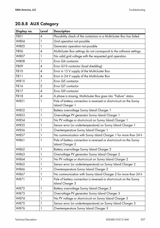
SMA America, LLC Troubleshooting
Technical Description SI5048U-TUS121440 207
20.8.8 AUX CategoryDisplay no. Level DescriptionF801 4 Plausibility check of the contactors in a Multicluster Box has failedW804 1 Grid operation not possibleW805 1 Generator operation not possibleF806 4 Multicluster Box settings do not correspond to the software settings.W807 1 No valid grid voltage with the requested grid operationW808 1 Error Q4 contactorF809 4 Error Q10 contactor (load shedding)F810 4 Error in 15 V supply of the Multicluster BoxF811 4 Error in 24 V supply of the Multicluster BoxW815 1 Error Q5 contactorF816 2 Error Q7 contactorF817 4 Error Q9 contactorF818 4 A phase is missing, Multicluster Box goes into ”Failure” statusW851 1 Pole of battery connection is reversed or short-circuit on the Sunny
Island Charger 1W852 1 Battery overvoltage Sunny Island Charger 1W853 1 Overvoltage PV generator Sunny Island Charger 1W854 1 No PV voltage or short-circuit on Sunny Island Charger 1W855 1 Sensor error (or undertemperature) on Sunny Island Charger 1W856 1 Overtemperature Sunny Island Charger 1W857 1 No communication with Sunny Island Charger 1 for more than 24 hW861 1 Pole of battery connection is reversed or short-circuit on the Sunny
Island Charger 2W862 1 Battery overvoltage Sunny Island Charger 2W863 1 Overvoltage PV generator Sunny Island Charger 2W864 1 No PV voltage or short-circuit on Sunny Island Charger 2W865 1 Sensor error (or undertemperature) on Sunny Island Charger 2W866 1 Overtemperature Sunny Island Charger 2W867 1 No communication with Sunny Island Charger 2 for more than 24 hW871 1 Pole of battery connection is reversed or short-circuit on the Sunny
Island Charger 3W872 1 Battery overvoltage Sunny Island Charger 3W873 1 Overvoltage PV generator Sunny Island Charger 3W874 1 No PV voltage or short-circuit on Sunny Island Charger 3W875 1 Sensor error (or undertemperature) on Sunny Island Charger 3W876 1 Overtemperature Sunny Island Charger 3

Troubleshooting SMA America, LLC
208 SI5048U-TUS121440 Technical Description
W877 1 No communication with Sunny Island Charger 3 for more than 24 hW881 1 Pole of battery connection is reversed or short-circuit on the Sunny
Island Charger 4W882 1 Battery overvoltage Sunny Island Charger 4W883 1 Overvoltage PV generator Sunny Island Charger 4W884 1 No PV voltage or short-circuit on Sunny Island Charger 4W885 1 Sensor error (or undertemperature) on Sunny Island Charger 4W886 1 Overtemperature Sunny Island Charger 4W887 1 No communication with Sunny Island Charger 4 for more than 24 hF890 2 Fault at the external measuring point of the Multicluster BoxF891 2 Fault at the external measuring point of the Multicluster Box slave 1F892 2 Fault at the external measuring point of the Multicluster Box slave 2
Display no. Level Description

SMA America, LLC Troubleshooting
Technical Description SI5048U-TUS121440 209
20.9 TroubleshootingAnswers are provided below for failures that may occur in practice:Why does the Sunny Island not connect to the running generator?
• Is the fuse on the generator ok?• Has the power which is allowed to be fed back into the generator during the permissible time
been exceeded (”233.14 GnRvTm” parameter)? If yes, ”!” is displayed. Generator connection is blocked for the set time. Set the ”#540.02 GnAck” parameter to Ackn.
• If the generator control relay (GnReq) is open has the generator been started manually (”234.07 GnStrMod” parameter)? Change the setting to autostart, if required.
• Is a GenMan used in the system?– Check the return signal (DigIn)– The generator can only be started manually using GenMan.
Why is the display of the Sunny Island dark and why is nothing shown on the display?
• Is the DC circuit breaker on the Sunny Island set to ”On”? In this case, the device has switched off to protect the battery against deep discharge (see also section 13.3 ”State of Charge (SOC) and State of Health (SOH)” (page 106)). To restart the Sunny Island, see section 9.5 ”Reactivating the Device Following Automatic Shutdown” (page 74).
• The external battery fuse may have been triggered.Why is it not possible to change parameters?
• Has the installer password been entered correctly? Check whether you are actually in ”Installer Level” (see section 10.5 ”Entering the Installer Password” (page 85)). If necessary, repeat the calculation and entry of the password.
• You are in the ”100-Meters” (measuring data) menu or the ”300-Diagnose” (diagnosis) menu. You can only read the data values shown here.
• Some parameters can only be changed in standby mode or in the QCG (see for example the parameter ”234.07 GnStrMod” in section 19.2 ”Adjustable parameters” (page 159)). Stop the Sunny Island as described in section 9.2 ”Stopping (Standby)” (page 73). Note that this causes a dropout in the off-grid power system and the loads are no longer supplied.
Why does the Sunny Island connect to the running generator only for a short time?
• The limits for the maximum permissible AC voltage or the minimum permissible frequency of the generator are too strict (parameter in the menu ”233# Generator Control”). Change voltage and/or frequency limits while observing the technical data for your generator.

Troubleshooting SMA America, LLC
210 SI5048U-TUS121440 Technical Description
Why does the ”VAC-Low” error (output voltage too low) also occur when the Sunny Island is started?
• A permanent short-circuit exists in the off-grid power system. Check the AC output connections of the off-grid power system (see section 6.3 ”AC Connection” (page 46)).
• The loads connected to the off-grid power system are too heavy. The power/electrical energy of the Sunny Island is not sufficient to supply the loads. Switch off some of the loads and restart the Sunny Island.
Why is the off-grid frequency not at 60 Hz?• The Sunny Boy inverter is controlled via the frequency (see section 17.5 ”Frequency Shift Power
Control (FSPC)” (page 147)).• The ”AFC” function of the Sunny Island 5048U is activated (see section 12.6 ”Automatic
Frequency Control (AFC)” (page 104)).• Power fluctuations cause frequency deviations.
What do I do when a battery cell can no longer be used?• Remove the unusable cell from your battery bank. Start the Sunny Island and change the battery
voltage in the QCG under ”New Battery”.What can I do when the QCG does not run?
• Switch off the Sunny Island (see section 9.3 ”Switching off” (page 74)) and restart it (see section 9.1 ”Switching on” (page 72)).
What happens when ”MMC operation failed” is displayed?• You wanted to perform an action using the SD card, but it failed (see section 10.9 ”Display of
Warnings and Failures” (page 91)). Check the card (on your PC/laptop) and use a new SD card, if necessary.
Why does my Sunny Island stay on even though I switched the DC circuit breaker to Off?
• Your Sunny Island may be powered by the AC side. Switch off all AC loads and disconnect them from the Sunny Island (see section 9.4 ”Disconnecting the Device from Voltage Sources” (page 74)).
Why is my battery discharging even though the generator is running?• The power produced by the generator does not reach the Sunny Island. Check the voltage and
frequency values. The fuses on the generator may have been triggered.• The consumer power exceeds the generator power ”234.03 GnCurNom”.
– Check error messages Find the cause. Why is the deactivation defined by the SOC in case of a full or equalization charge and generator start in the second time zone?
• Equalization charge has a higher priority than silent time.

SMA America, LLC Troubleshooting
Technical Description SI5048U-TUS121440 211
Why is the SOC not at 100 % even after full charging has been completed?• Set a longer absorption period.
How is it possible to ensure that the maximum battery charging current is correctly calculated after a reinstallation of the battery current sensor?
• Re-calibrate the battery current sensor using the ”225.04 BatCurAutoCal” parameter with the setting ”Start”.
What is required if the Sunny Island is continuously switched off after Low Battery Mode (LBM) when restarting the device?
• Start the generator manually, if required (e.g.: Run1h). Consider the time for warming up: 5 minutes without charging current in BatProtMode can cause the device to change to standby mode.
How is it possible to change between wintertime and summertime operation e.g. in case of alpine huts?
• Save two different parameter sets on the SD card and activate them via the ”550.02 ParaLod” parameter (see section 11.3 ”Saving and Loading Parameters” (page 96).
What happens if the card inserted is not FAT16 formatted?• The Sunny Island displays the message ”Incomp”.
Why does the generator and/or the grid not reconnect although the (voltage or frequency) limit for disconnection has not been exceeded?
• The Sunny Island connects with a so-called hysteresis, i.e., the connection value is slightly below or above the disconnection value. These threshold values are predefined ex-works.
Why is it not possible to set any combinations of voltage and frequency limits?• The possible ranges for voltage and frequency of the Sunny Island allow the combination of
special frequencies and voltages that result in transformer saturation and are therefore not permitted.
Why is it that one (or more) extension clusters remain in standby, although the main cluster is operating properly?
• Is the communication cable between the master devices connected? The main master cannot forward the ”Start” command to the extension master. The devices remain in standby.
Why is the Multicluster system not supplying full power output?• Has an extension cluster's slave failed? The system continues to operate, but with
correspondingly lower output on the phase of the failed device.Why is it that shortly after startup, the slave switches to standby with the failure message F117, but the master continues to operate?
• Are the phases within the cluster, or from the cluster to the Multicluster Box connected the wrong way around? This causes a permanent short-circuit in the cluster, and the slave reports this to the master.

Troubleshooting SMA America, LLC
212 SI5048U-TUS121440 Technical Description
What is the meaning of the F605 error message?• The F605 error message might occur, among other things, if you have installed a direct
connection with switch between the AC input (AC2) and the AC output (AC1) of the Sunny Island. If such a connection is not installed on the Sunny Island and if the switch is closed, the Sunny Island is surpassed. If the Sunny Island did not give the order for closing its internal transfer relay itself, it displays the F605 error message and does not start operation. Open the bypass switch and restart the Sunny Island afterwards to fix this error.
Why is it that high outputs are being transferred back and forth between the clusters in the cluster network?
• The nominal frequencies and voltages are defined differently. Correct this by means of the appropriate parameters.
20.10 Procedure During Emergency Charge ModeThe Sunny Island cannot provide voltage with full amplitude with a deeply discharged battery and can no longer synchronize with an existing grid or generator. Using the emergency charge mode (ECM), it is possible to charge the batteries in current-controlled mode.To charge the batteries in the emergency charge mode, either bridge the AC1 with AC2 (for a stationary generator) or connect a portable generator directly to AC1.All loads must be disconnected in emergency charge mode.
Emergency charge mode is activated in the QCG. For a description how to access the QCG see section 8.2 ”Starting the Quick Configuration Guide (QCG)” (page 66). Follow the instructions up to point 2. The emergency charge mode is described below.1. Choose ”Emerg Charge” in QCG with <ENTER>.
Battery ManagementThe battery management is active and the current set battery parameters and the current charging phase are used. These values can be changed in ”normal operation”.Generator and Grid ManagementIn emergency charge mode, no generator management and no grid management are active. Reverse power protection and relay protection are also not active.AC1 and AC2 are bridgedIn case that AC1 and AC2 have been bridged the generator should be connected and then manually started. Otherwise, it is possible that the magnetizing current trips the generator fuse. (This can also happen when connecting the relay without using a bridge.)

SMA America, LLC Troubleshooting
Technical Description SI5048U-TUS121440 213
2. Confirm the following view with <ENTER>.
3. Set the maximum external current, e.g., the generator current.
4. Confirm the set value with <ENTER>.
5. Use the down arrow key. The notification shown here is displayed.
6. Press <ENTER> to confirm.
7. Press <ENTER>.
The emergency charge mode starts.Interrupt the emergency charge mode, e.g., in order to refill diesel.1. Press <Enter> to stop the Sunny Island.
The notification shown here is displayed.
2. Press and hold <Enter>. The remaining time is displayed as a bar.
The emergency charge mode is interrupted. The notification shown here is displayed.
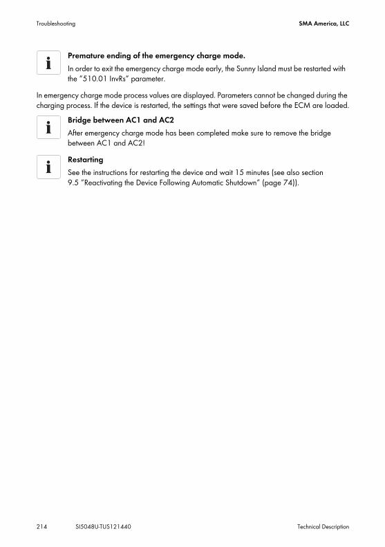
Troubleshooting SMA America, LLC
214 SI5048U-TUS121440 Technical Description
In emergency charge mode process values are displayed. Parameters cannot be changed during the charging process. If the device is restarted, the settings that were saved before the ECM are loaded.
Premature ending of the emergency charge mode.In order to exit the emergency charge mode early, the Sunny Island must be restarted with the ”510.01 InvRs” parameter.
Bridge between AC1 and AC2After emergency charge mode has been completed make sure to remove the bridge between AC1 and AC2!RestartingSee the instructions for restarting the device and wait 15 minutes (see also section 9.5 ”Reactivating the Device Following Automatic Shutdown” (page 74)).

SMA America, LLC Accessories
Technical Description SI5048U-TUS121440 215
21 AccessoriesYou will find the corresponding accessories and replacement parts for your product In the following overview. If needed, you can order these from SMA or your dealer.Designation Brief description SMA order numberBatfuse‑B.01 (250 A)(not UL certified)
2-pole NH1 battery fuse switch disconnector for up to one Sunny Island, 3 DC input ports (1 x Battery and 2 x Sunny Island Chargers), 1 x auxiliary voltage output with 8 A.
BATFUSE-B.01
Batfuse‑B.03 (250 A)(not UL certified)
2-pole NH1 battery fuse switch disconnector for up to 3 Sunny Island inverters, 6 DC input ports (2 x Battery and 4 x Sunny Island Chargers), 1 x auxiliary voltage output with 8 A.
BATFUSE-B.03
Load-shedding contactor
3-pole load-shedding contactor with a 48 V coil for Sunny Island.The load-shedding contactor is available in several versions. You can obtain more information from SMA or your dealer.
SI-LSXX
SI-Shunt Measuring resistor for battery current detectionThe measuring resistor is available in several versions. You can obtain more information from SMA.
SI-SHUNTXXX
Sunny Island Charger (not UL-certified)
Solar charge regulator for Sunny Island systemsBattery voltage: 48 V/24 V/12 VBattery current: 40 A at 48 V, 50 A at 12 V/24 VNominal power: 2,000 W at 48 V, ´max. PV voltage: 140 V
SIC50-MPT
Smart Load 6000 Adjustable dumpload SL 6000RS485 upgrade kit RS485 interface 485PB-G3Multicluster Piggy-Back Interface for communication between the Sunny
Island and the Multicluster BoxMC-PB
Sunny Island Charger Piggy-Back
Interface for communication between the Sunny Island and Sunny Island Charger
SIC-PB

Technical Data SMA America, LLC
216 SI5048U-TUS121440 Technical Description
22 Technical DataOutput ValuesNominal AC voltage (adjustable) UAC, nom 120 V (105 V … 132 V)Nominal frequency fnom 60 Hz (55 … 65 Hz)Continuous AC output at 77 °F (25 °C) Pnom 5 000 WContinuous AC output at 113 °F (45 °C) Pnom 4 000 WAC output power for 30 min at 77 °F (25 °C) P30min 6 500 WAC output power for 1 min at 77 °F (25 °C) P1min 8 400 WAC output power for 3 seconds at 77 °F (25 °C) P3sec 11 000 WNominal AC current IAC, nom 41.7 AMaximum current (peak value) for 60 ms IAC max 180 AHarmonic distortion of output voltage KVAC < 3 %Power factor cosφ –1 … +1
Input dataInput voltage (adjustable) UAC, ext 120 V (80 V … 150 V)Input frequency (adjustable) fext 60 Hz ( 54 Hz … 66 Hz)Maximum AC input current (adjustable) IAC, ext 56 A (0 A … 56 A)Maximum input power PAC, ext 6.7 kW
Battery DataBattery voltage (range) UBat, nom 48 V (41 V … 63 V)Maximum battery charging current IBat, max 120 AContinuous charging current IBat, nom 100 ABattery capacity CBat 100 Ah … 10 000 AhCharge control IUoU procedure with automatic
full and equalization chargeBattery type VRLA/FLA/NiCd
Efficiency / Power consumptionMaximum efficiency 95 % (at 1 000 W)Efficiency > 90 % 5 … 120 % Pnom

SMA America, LLC Technical Data
Technical Description SI5048U-TUS121440 217
Efficiency curve
Internal consumption with no load (in standby mode)
25 W (< 4 W)
General dataDimensions (W x H x D in mm) 467 x 612 x 235Weight approx. 139 lb.
(approx. 63 kg)Certification UL 1741/UL1998Protection rating NEMA Type 1Device Protection short-circuit, overload,
overtemperatureAmbient temperature − 13 °F … 122 °F
( − 25 °C … +50 °C)
Efficiency / Power consumption

Technical Data SMA America, LLC
218 SI5048U-TUS121440 Technical Description
Interfaces SI 5048UNumber of LEDs 2Number of buttons 4Display 2-line displayMulti-function relays 2Communication RS485, galvanically isolated
(optional)Memory card SD CardDigital input level (Dig-In) High level starting at 5 V
(up to 63 V), low level 0 V … 2 VLoad limits for multi-function relays 1 and 2 AC: 6 A at 250 V
DC: see graphicLoad limitation curve

SMA America, LLC Glossary
Technical Description SI5048U-TUS121440 219
23 GlossaryAbsorption phaseConstant Voltage phase: A charging phase using constant charging voltage. The charging current constantly decreases in this phase.ACAbbreviation for ”Alternating Current”.AC couplingThe AC side connection between loads, generators and storage devices.AGM batteryAbsorbent Glass Mat separator battery. This is a battery where the electrolyte (a mixture of water and sulfuric acid) is bound to a glass fiber mat. This is a type of a sealed or valve regulated lead-acid (VRLA) lead acid battery. A gas mixture (hydrogen and oxygen) is always generated when lead-acid batteries are charged and in normal operation this internally recombines to form water. This removes the need for regularly refilling the battery cells with water, which is why these batteries are often described as ”low maintenance” or even ”maintenance free”. AGM batteries are available from many different manufacturers for a wide range of applications. They usually have very good high current properties but are not very deep-discharge-cycle resistant.AhAbbreviation for ”Ampere hours”. Unit of electrical charge, one ampere hour is the charge provided by a constant current of 1 A over a period of one hour.Backup systemBackup systems are power supply systems that provide an extra level of security for standard power supply systems. The public grid is usually the standard power supply system and the backup system is provided by an additional stand-alone grid in the case of a power outage. In addition to the backup systems, diesel generators in PV battery systems are also described as backup generators. Here they perform the same task as a backup system for the public grid.BatteryA battery is an electrochemical storage device that can release previously stored chemical energy as electrical energy. A distinction is made between non-rechargeable batteries (often used in consumer markets) and rechargeable batteries (accumulators). In stand-alone grid systems, lead acid batteries are almost always used and, very rarely, Nickel/Cadmium batteries are used as secondary rechargeable batteries.Battery bankSee Battery system.

Glossary SMA America, LLC
220 SI5048U-TUS121440 Technical Description
Battery charge modeAn operating mode of a battery inverter in which the inverter takes energy from the AC grid to charge the batteries in a controlled fashion. In this mode of operation, the battery inverter is responsible for correctly charging the batteries and acts like an independent battery charger.Battery inverterSee Battery power converter.Battery managementThe battery management is responsible for the optimum charging of the battery bank and for protection against deep discharge. This is the only way of ensuring that the battery service life reflects the manufacturer's specifications.Battery power converterA bidirectional power converter that can regulate voltage and frequency in a standalone grid as well as correctly charging the batteries.Battery systemThe combination of serial and possibly also parallel connection of several identical batteries. Battery banks of 12 V, 24 V, 48 V and 60 V are typical.Boost chargeRapid charging: Allows the batteries to be charged to a level of approx. 85 – 90 % in the shortest time and the most efficient manner.Bulk phaseI-Phase: The charging phase in which charging can be done using the maximum allowable charging current.CapacityDescribes the storage capability of a cell or battery, specified in Ah (ampere hours). The capacity of a battery is heavily dependent on the charging cycle, the amount of current drawn and the temperature.CECAbbreviation for California Energy CommissionCentral inverterAn inverter concept, in which all PV modules are connected to each other (in series and/or parallel) and which uses a single inverter for feeding energy into the mains supply grid. The low cost of the inverter is usually offset by the much higher installation efforts required and possible yield losses due to variations in shadowing of different solar modules.Charge modeSee Battery charging mode.

SMA America, LLC Glossary
Technical Description SI5048U-TUS121440 221
C-rateThe nominal capacity specification is always provided with the discharge time on which the capacity is based. The nominal capacity is the product of the constant discharging current IN and the discharge time tN, that passes between commencement of discharging the fully charged battery until the final discharge voltage VS is reached. In permanently on-site batteries, the C10 capacity is usually specified. i.e. a battery with C10 = 200 Ah can be discharged for 10 hours at a nominal current of 0.1 x C10 = I10 = 20 A.DCAbbreviation for ”Direct Current”DeratingA controlled reduction in performance, usually dependent on component temperatures. Derating is used instead of performing a complete shutdown of the system.DSPAbbreviation for Digital Signal Processor. A DSP is a microprocessor chip especially developed for digital signal processing and control.ElectrolyteA chemical solution that allows the conduction of ions within a battery. In lead acid batteries, the electrolyte is diluted sulfuric acid and is also a reactant in the electrochemical reaction. Nickel/Cadmium batteries use an alkaline electrolyte (potassium hydroxide).EPROMSee Flash EEPROMEqualize chargeEqualize charge: Allows multiple series-connected battery cells to be charged to a unified state of charge of 95 – 100 %. Without regular equalization charging, the state of charges of the various cells slowly drift apart, which can lead to poor battery performance and premature battery bank failure.FirmwareFirmware is software that is stored in a chip in various electronic devices, such as Sunny Island, hard disk recorders, DVD burners and players, newer television sets, household appliances and computers ‒ in contrast to software that is stored on a hard drive, CDROM or other media. These days, firmware is usually stored in Flash memory or an EEPROM chip.FLAFlooded Lead Acid battery: A lead acid battery with liquid electrolyte, also often described as a sealed lead acid battery.

Glossary SMA America, LLC
222 SI5048U-TUS121440 Technical Description
Flash EEPROMThe abbreviation EEPROM stands for Electrically Erasable Programmable Read-Only Memory. Flash memory is a digital storage chip, the exact designation is Flash EEPROM. In contrast to ”normal” EEPROM storage, individual bytes (the smallest addressable storage units) cannot be deleted. EEPROM is a non-volatile, electronic storage component that is used in the Sunny Island, the computer industry (among others) and usually in Embedded Systems. Flash EEPROMs are used where information must be permanently stored in the smallest amount of space, e.g. for storing the firmware.Float chargeMaintenance charge: Allows the batteries to be slowly charged to a state of charge of 100 % without the negative effects of overcharging. Complete charging to 100 % using float charge takes several days. For this reason, float charging is more important for grid backup systems and less important for stand-alone grids.Full chargeRecharging of the batteries to a level of approx. 95 % on a regular basis (at least once a month). This efficiently avoids premature aging of the batteries caused by inadequate charging.Gel batteryA type of battery in which the electrolyte (a mixture of water and sulfuric acid) is bound into a gel. This is a type of sealed or valve regulated (VRLA) lead acid battery. A gas mixture (hydrogen and oxygen) is always generated when lead acid batteries are charged, and in normal operation this internally recombines to form water. This removes the need for regularly refilling the battery cells with water, which is why these batteries are often described as ”low maintenance” or even ”maintenance free” (see also AGM batteries). Gel batteries are available from many different manufacturers for a wide range of applications. There are Gel batteries for high-current applications but also for cycle operation with very good deep-cycle resistance.Grid-coupled systemPV system that is connected to the power supply grid of an external energy supplier, such as the utility company.InvertersA device for converting the direct current (DC) from the PV generator into alternating current (AC), which is used by most normal household devices and especially for feeding energy into an existing supply grid. Inverters for PV systems usually include one or more MPP trackers, store operating data and monitor the grid connections of the PV system (see also MSD).Inverter modeSee Inverter operationInverter operationOperating mode of a battery inverter where it supplies the stand-alone grid from the battery energy. In this operating mode, the battery inverter is especially responsible for the control of frequency and voltage in the stand-alone grid.

SMA America, LLC Glossary
Technical Description SI5048U-TUS121440 223
Maximum Power Point ”MPP”The working point (current/voltage characteristic curve) of a PV generator where the maximum power can be drawn. The actual MMP changes constantly depending (e.g.) on the level of solar irradiation and the ambient temperature.MPP trackerRegulation of the power drawn so that a PV array remains as close as possible to the MPP. This working point varies with the solar irradiation and the temperature conditions of the modules. MPP tracking optimizes the extraction of electrical power and is a feature of inverters and charge controllers.MSDSee Independent disconnection device.Multi-string inverterAn inverter that combines the advantages of several string inverters (separate MPP tracking of individual strings) and a central inverter (lower performance specific costs).NiCdNickel/Cadmium battery, contains Nickel, Cadmium, and potassium hydroxide as the electrolyte. They require a significantly higher charging voltage, have a lower level of efficiency and are significantly more expensive than lead acid batteries. Their robustness, cycle resistance and low-temperature capabilities allow them to be used in certain special applications.Overload capabilityThe overload capability of an inverter describes the ability of the inverter to supply shortterm (seconds or minutes) excessive loads, that can be significantly higher than the nominal capacity in battery inverters. The overload capability is important to allow electrical machines with a nominal power output close to the nominal power output of the standalone grid inverter to be started, since these machines typically require six times the nominal current when starting.Parallel connectionParallel connection of the batteries (all positive poles together and all negative poles together) increases the capacity of the battery bank while keeping the voltage constant. Example: Two 24 V/100 Ah batteries connected in parallel still have a voltage of 24 V, but have a capacity of 100 Ah + 100 Ah = 200 Ah.Piggy-Back (Board)A printed circuit board that is plugged into another board to increase performance or expand capabilities. A piggy-back board can also replace a single chip. In this case, the chip is removed and the board is plugged into the empty socket.

Glossary SMA America, LLC
224 SI5048U-TUS121440 Technical Description
PLCAbbreviation for Power Line Communication: Describes the process of data transfer over the grid supply cables. The PLC power module is used to amplify the signal and is connected in Multi-String and Sunny Mini Central inverters. Powerline communication is not suitable for Sunny Island inverters.Protected loads panelSee ”Stand-alone grid system”.PVPhotovoltaics (PV) is the conversion of solar irradiation into electrical energy using special semiconductors called solar cells.PV arraySee PV generator.PV generatorTechnical device for the conversion of light energy into electrical energy. All the series and parallel mounted and electrically connected solar modules in a PV system are known as the PV generator.PV moduleSee Solar module.PV systemDescribes a solar power system for generating electrical power. Describes the complete collection of components needed for the acquisition and utilization of solar energy. As well as the PV generator, this includes the Sunny Boy or Sunny Mini Central, for example, in the case of grid-coupled systems.Self dischargeLoss of battery charge while it is stored or not used. A higher ambient temperature has a strong influence on self discharge.Series connectionIn this case the positive pole of each battery is connected to the negative pole of the next battery. There is only one circuit where current can flow. Series connection increases the voltage of the entire battery bank. If four 12 V batteries with a capacity of 100 Ah each are connected in series, the total voltage is 4 x 12 V = 48 V, while the total capacity remains at 100 Ah.SOCState of Charge: The state of charge of the batteries, see State of Charge. If (e.g) 25 Ah is taken from a 100-Ah battery, the state of charge (SOC) is then 75 %.Solar energy”Sun energy”, this means energy from sunlight or other solar irradiation (heat and/or UV radiation).

SMA America, LLC Glossary
Technical Description SI5048U-TUS121440 225
Solar moduleElectrical connection of several solar cells encapsulated in a housing to protect the sensitive cells from mechanical stress and environmental effects.Solar cellAn electronic component that generates electrical energy when irradiated with sunlight. Since the voltage produced by a solar cell is very small (approx. 0.5 V), several solar cells are combined in series to form a solar module. The most common semiconductor material presently used for solar cells is silicon, which is manufactured in different forms (monocrystalline, polycrystalline, amorphous). In addition to different mechanical variations, that are usually designed to increase the level of efficiency, completely new materials are currently being tested (Cadmium Telluride, Cadmium Indium Sulphide, Titanium Dioxide and many others.)Split phaseA split phase power supply system is a 3-wire single-phase distribution system, commonly used in North America, UK, Australia and New Zealand for single-family residential and light commercial (up to about 100 kVA) applications. Its primary advantage is that it saves conductor material over a single ended single phase system while only requiring single phase on the supply side of the distribution system. Since there are two live conductors in the system, it is sometimes incorrectly referred to as ”two phase”. To avoid confusion with split phase applications, it is appropriate to call this power distribution system a 3-wire, single-phase, mid-point neutral system.Stand-alone grid systemAn energy generation system that is completely independent of any external power sources.State of ChargeDescribes the current amount of charge that can be drawn from the battery, in percent of the nominal capacity (100 % = battery full, 0 % = battery empty).StringDescribes a group of solar modules connected in series. A PV system usually consists of a number of strings, which avoids yield losses due to variations in shading over different modules.String inverterAn inverter concept that avoids the disadvantages of the central inverter concept. The PV is split into individual strings, each of which is connected to the external mains supply with its own string inverter. This greatly simplifies installation and greatly reduces the yield losses caused by manufacturing deviations or variations in shadowing of the solar modules.VRLAValve Regulated Lead Acid battery: Lead-acid battery with semi-solid electrolyte or sealed lead acid battery. Examples of this type of battery are Gel batteries and AGM batteries (Absorbent Glass Mat).

Contact SMA America, LLC
226 SI5048U-TUS121440 Technical Description
24 ContactIf you have technical problems concerning our products, contact the SMA Service Line. We require the following information in order to provide you with the necessary assistance:
• Type of the Sunny Island• Serial number of the Sunny Island• Firmware version of the Sunny Island• Failure indication displayed• Type of battery connected• Nominal battery capacity • Nominal battery voltage• Communication products connected• Type and size of additional energy sources • Type of connected consumer loads• Power of the connected generator• Maximum current of the generator• Interface of the generator
SMA Solar Technology America, LLC6020 West Oaks Blvd, Ste 300Rocklin, CA 95765Tel. +1 916 625 0870Tel. +1 877‑MY SMA TECHTel. +1 877 697 6283 (Toll free, available for USA, Canada and Puerto Rico)Fax +1 916 625 0871Service@SMA‑America.comwww.SMA‑America.com


![Ichong vs. Hernandez [101 Phil 1155; L-7995; 31 May 1957]](https://img.pdfslide.us/doc/110x75/577c77e61a28abe0548def3f/ichong-vs-hernandez-101-phil-1155-l-7995-31-may-1957.jpg)