Embed Size (px)
Citation preview
Sungmin Bae, Hyung-Ock Kim, Jungyun Choi, and Jaehong Park
Design Technology
Infrastructure Design Center System-LSI Business Division
1. Motivation 2. Design flow 3. Parallel multiplier 4. Coarse-grained structural placement methodology 5. Experimental results 6. Future works
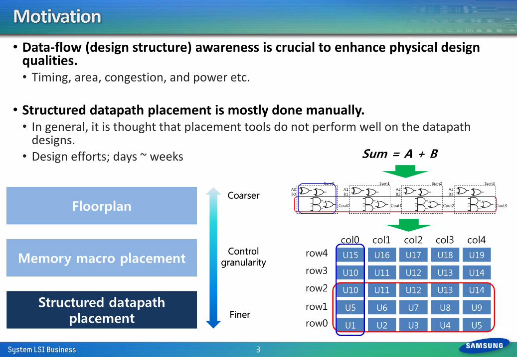
• Data-flow (design structure) awareness is crucial to enhance physical design qualities. • Timing, area, congestion, and power etc.
• Structured datapath placement is mostly done manually. • In general, it is thought that placement tools do not perform well on the datapath
designs. • Design efforts; days ~ weeks
3
Floorplan
Memory macro placement
Structured datapath placement
Coarser
Finer
Control granularity
Sum = A + B
Floorplan
Memory macro placement
Structured datapath placement
Coarser
Finer
Control granularity
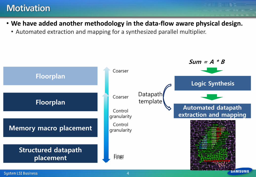
• We have added another methodology in the data-flow aware physical design. • Automated extraction and mapping for a synthesized parallel multiplier.
4
Sum = A * B
Floorplan
Memory macro placement
Coarse-grained structured datapath placement
Coarser
Finer
Control granularity
Structured datapath placement
Logic Synthesis
Automated datapath extraction and mapping
Datapath template
Floorplan
Memory macro placement
Structured datapath placement
Coarser
Finer
Control granularity
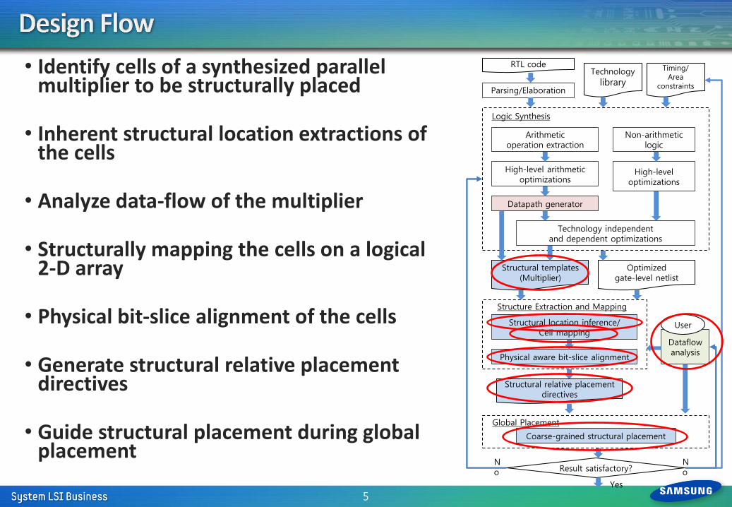
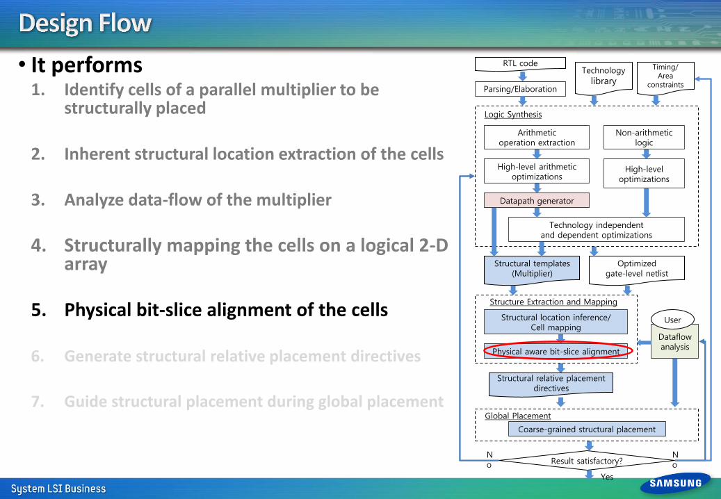
• Identify cells of a synthesized parallel multiplier to be structurally placed
• Inherent structural location extractions of the cells
• Analyze data-flow of the multiplier
• Structurally mapping the cells on a logical 2-D array
• Physical bit-slice alignment of the cells
• Generate structural relative placement directives
• Guide structural placement during global placement
5
Technology independent and dependent optimizations
RTL code
Datapath generator
Logic Synthesis
Physical aware bit-slice alignment
Optimized gate-level netlist
Structural templates (Multiplier)
Parsing/Elaboration
Arithmetic operation extraction
High-level arithmetic optimizations
Non-arithmetic logic
Dataflow analysis
High-level optimizations
Result satisfactory?
Structure Extraction and Mapping
User
Technology
library
Timing/ Area
constraints
Structural location inference/ Cell mapping
No
No
Yes
Coarse-grained structural placement
Structural relative placement directives
Global Placement
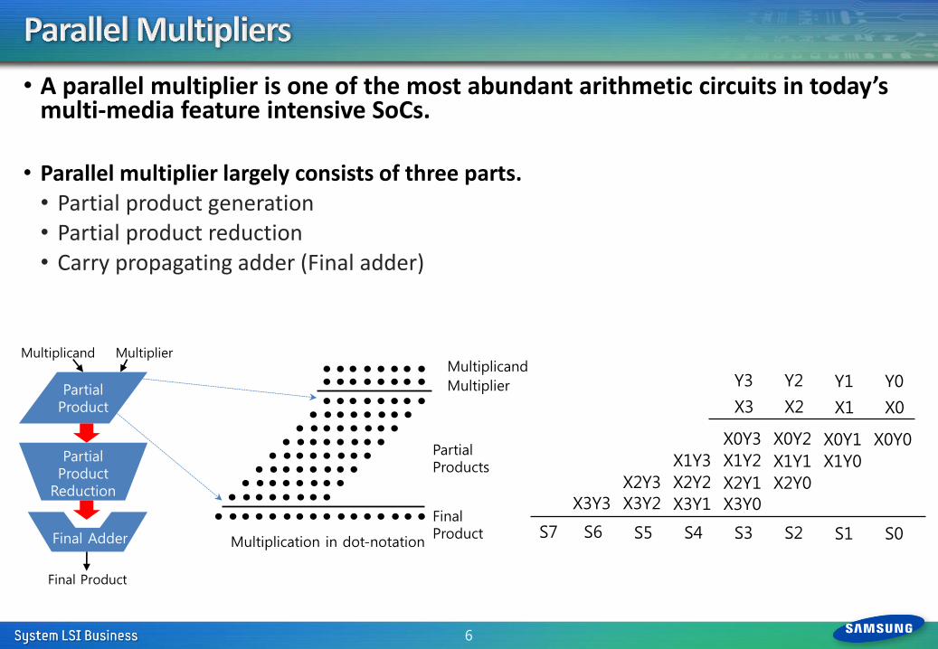
• A parallel multiplier is one of the most abundant arithmetic circuits in today’s multi-media feature intensive SoCs.
• Parallel multiplier largely consists of three parts. • Partial product generation • Partial product reduction • Carry propagating adder (Final adder)
6
Multiplicand
Multiplier
Partial Products
Final Product
Partial Product
Partial Product
Reduction
Multiplicand Multiplier
Final Adder
Final Product
Multiplication in dot-notation
X3Y3 X3Y2 X3Y1 X3Y0
X2Y3 X2Y2 X2Y1 X2Y0
X1Y3 X1Y2 X1Y1 X1Y0
X0Y3 X0Y2 X0Y1 X0Y0
S3 S2 S1 S0 S7 S6 S5 S4
X3 X2 X1 X0
Y3 Y2 Y1 Y0
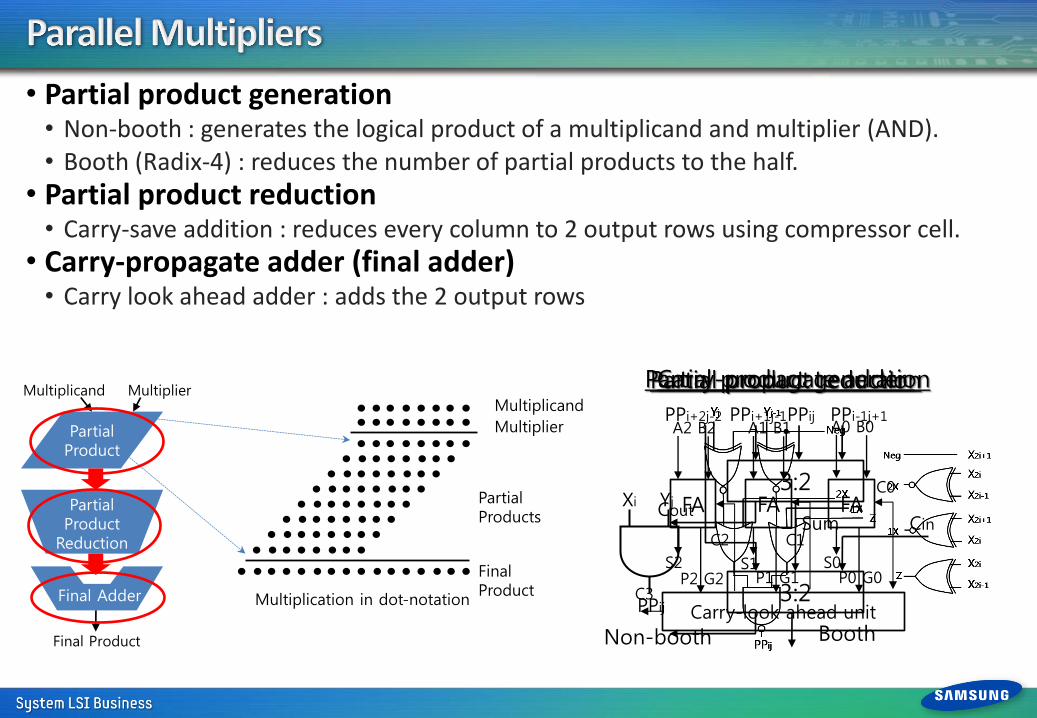
• Partial product generation • Non-booth : generates the logical product of a multiplicand and multiplier (AND). • Booth (Radix-4) : reduces the number of partial products to the half.
• Partial product reduction • Carry-save addition : reduces every column to 2 output rows using compressor cell.
• Carry-propagate adder (final adder) • Carry look ahead adder : adds the 2 output rows
Yj Xi
PPij
Booth Non-booth
Partial product generation
3:2
3:2
PPi-1j+1 PPij PPi+1j-1
Cin Cout
Sum
PPi+2j-2
Partial product reduction
Carry-look ahead unit
FA FA FA
A2 B2 A1 B1 A0 B0
S2 S1 S0
C2 C1
C0
C3 P2 G2 P1 G1 P0 G0
Carry-propagate adder Multiplicand
Multiplier
Partial Products
Final Product
Partial Product
Partial Product
Reduction
Multiplicand Multiplier
Final Adder
Final Product
Multiplication in dot-notation
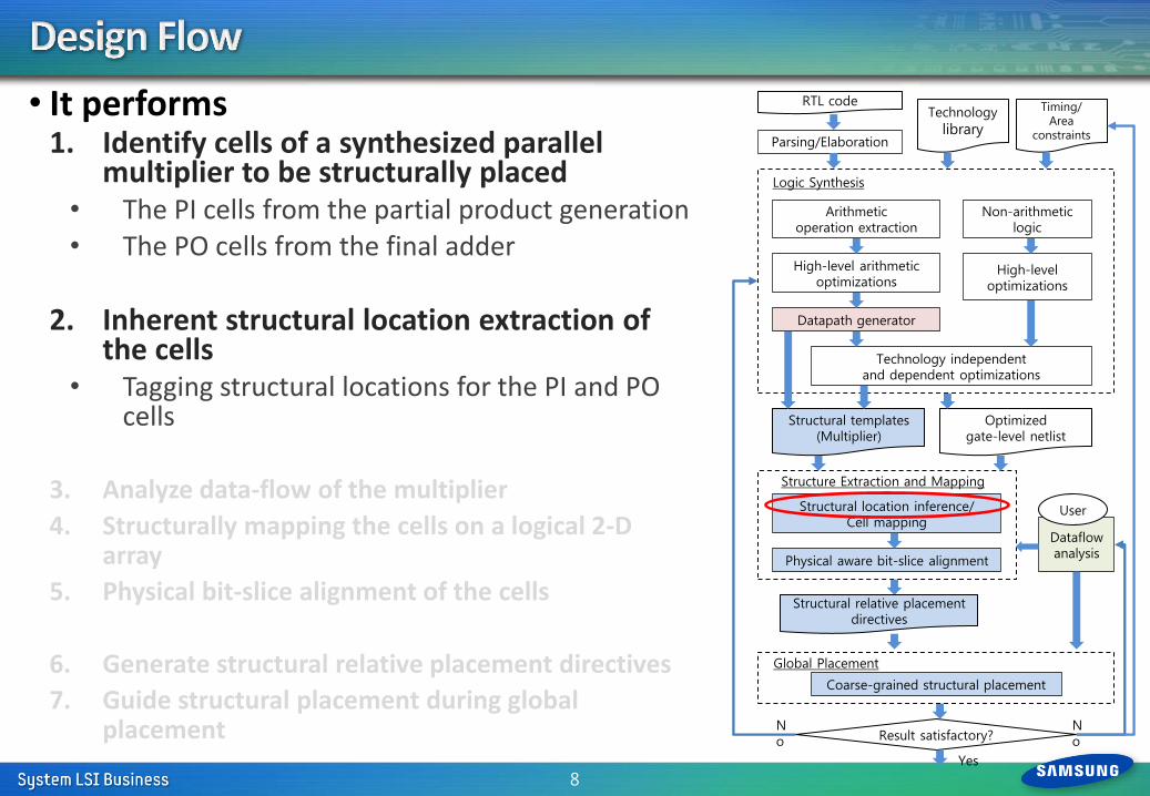
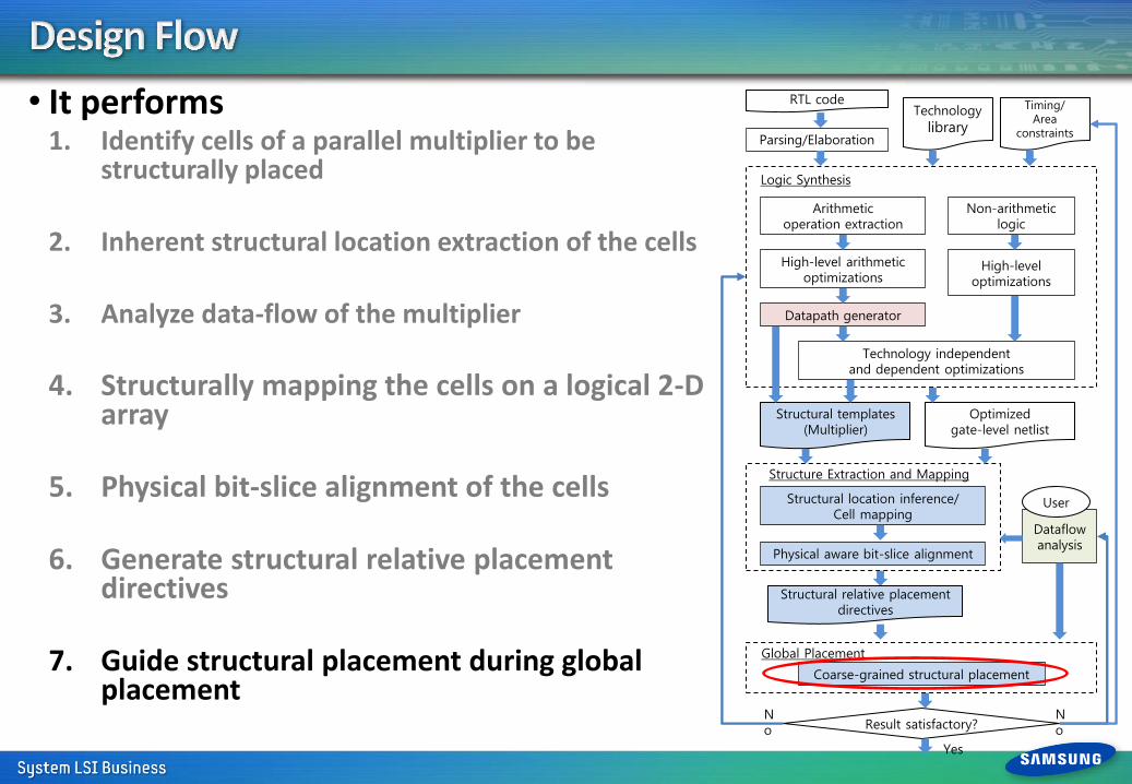
• It performs 1. Identify cells of a synthesized parallel
multiplier to be structurally placed • The PI cells from the partial product generation • The PO cells from the final adder
2. Inherent structural location extraction of
the cells • Tagging structural locations for the PI and PO
cells
3. Analyze data-flow of the multiplier
4. Structurally mapping the cells on a logical 2-D array
5. Physical bit-slice alignment of the cells
6. Generate structural relative placement directives
7. Guide structural placement during global placement
8
Technology independent and dependent optimizations
RTL code
Datapath generator
Logic Synthesis
Physical aware bit-slice alignment
Optimized gate-level netlist
Structural templates (Multiplier)
Parsing/Elaboration
Arithmetic operation extraction
High-level arithmetic optimizations
Non-arithmetic logic
Dataflow analysis
High-level optimizations
Result satisfactory?
Structure Extraction and Mapping
User
Technology
library
Timing/ Area
constraints
Structural location inference/ Cell mapping
No
No
Yes
Coarse-grained structural placement
Structural relative placement directives
Global Placement
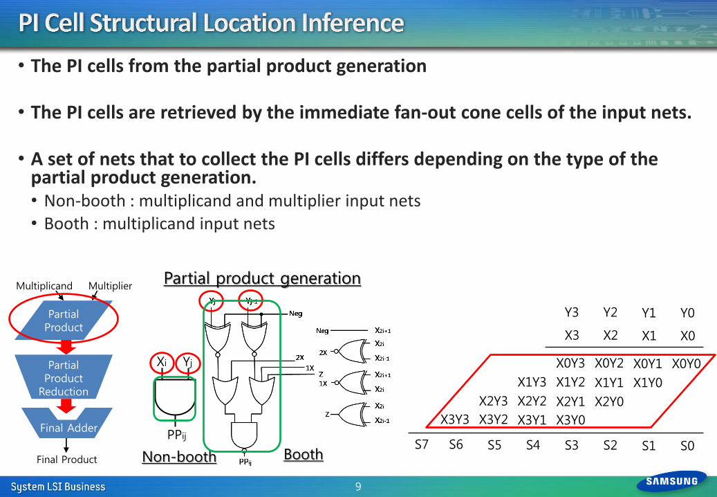
• The PI cells from the partial product generation
• The PI cells are retrieved by the immediate fan-out cone cells of the input nets.
• A set of nets that to collect the PI cells differs depending on the type of the partial product generation. • Non-booth : multiplicand and multiplier input nets • Booth : multiplicand input nets
9
Yj Xi
PPij
Booth Non-booth
Partial product generation
Partial Product
Partial Product
Reduction
Multiplicand Multiplier
Final Adder
Final Product
X3Y3 X3Y2 X3Y1 X3Y0
X2Y3 X2Y2 X2Y1 X2Y0
X1Y3 X1Y2 X1Y1 X1Y0
X0Y3 X0Y2 X0Y1 X0Y0
S3 S2 S1 S0 S7 S6 S5 S4
X3 X2 X1 X0
Y3 Y2 Y1 Y0
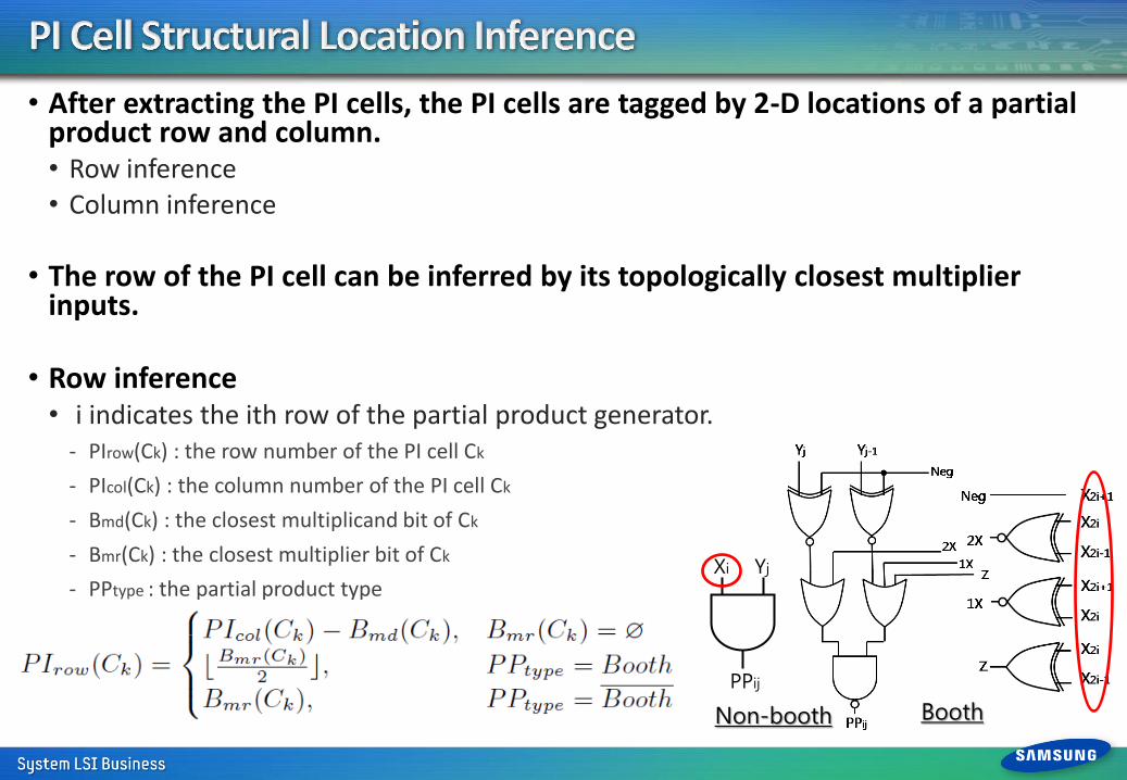
• After extracting the PI cells, the PI cells are tagged by 2-D locations of a partial product row and column. • Row inference • Column inference
• The row of the PI cell can be inferred by its topologically closest multiplier inputs.
• Row inference • i indicates the ith row of the partial product generator.
- PIrow(Ck) : the row number of the PI cell Ck
- PIcol(Ck) : the column number of the PI cell Ck
- Bmd(Ck) : the closest multiplicand bit of Ck
- Bmr(Ck) : the closest multiplier bit of Ck
- PPtype : the partial product type
Yj Xi
PPij
Booth Non-booth
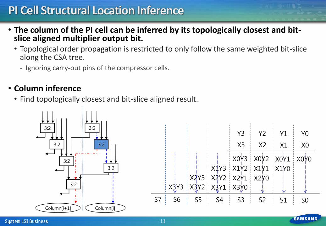
• The column of the PI cell can be inferred by its topologically closest and bit-slice aligned multiplier output bit. • Topological order propagation is restricted to only follow the same weighted bit-slice
along the CSA tree. - Ignoring carry-out pins of the compressor cells.
• Column inference • Find topologically closest and bit-slice aligned result.
11
3:2
3:2
3:2
3:2
3:2
3:2
3:2
Column[i+1] Column[i]
X3Y3 X3Y2 X3Y1 X3Y0
X2Y3 X2Y2 X2Y1 X2Y0
X1Y3 X1Y2 X1Y1 X1Y0
X0Y3 X0Y2 X0Y1 X0Y0
S3 S2 S1 S0 S7 S6 S5 S4
X3 X2 X1 X0
Y3 Y2 Y1 Y0
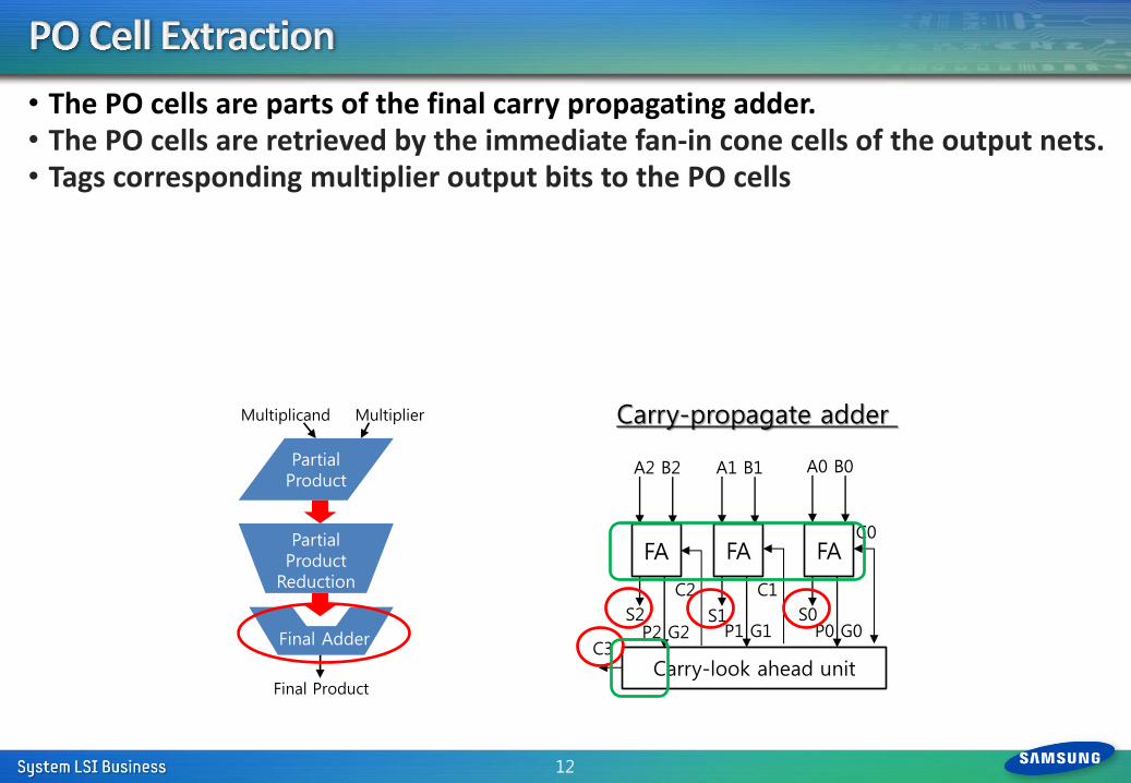
• The PO cells are parts of the final carry propagating adder. • The PO cells are retrieved by the immediate fan-in cone cells of the output nets. • Tags corresponding multiplier output bits to the PO cells
12
Carry-look ahead unit
FA FA FA
A2 B2 A1 B1 A0 B0
S2 S1 S0
C2 C1
C0
C3 P2 G2 P1 G1 P0 G0
Carry-propagate adder
Partial Product
Partial Product
Reduction
Multiplicand Multiplier
Final Adder
Final Product
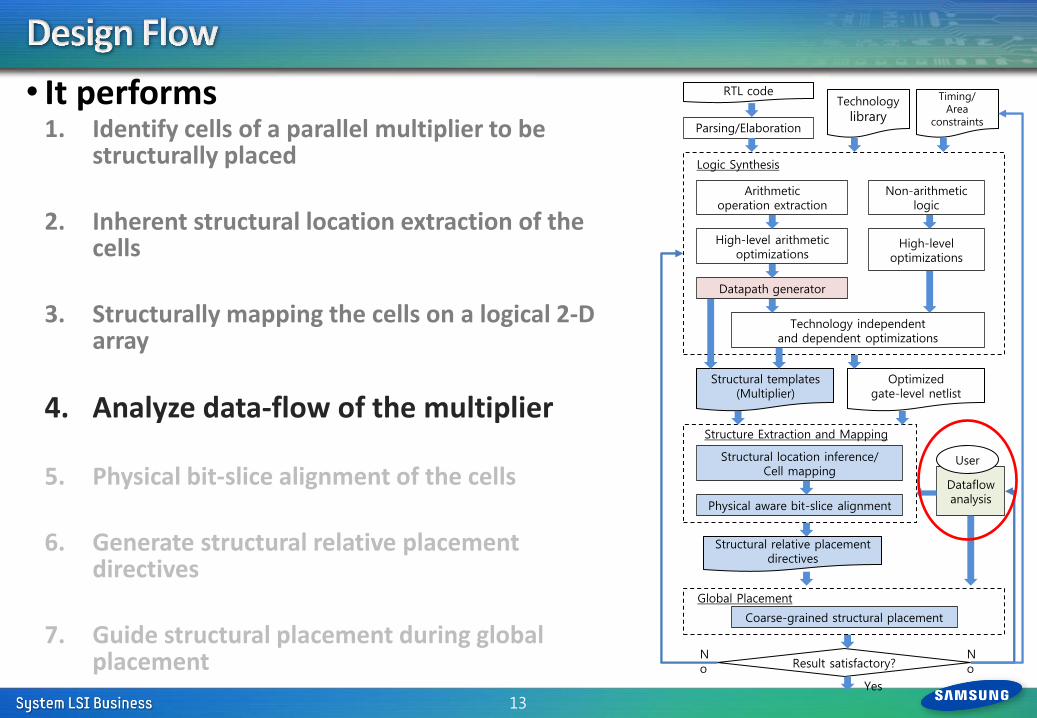
• It performs 1. Identify cells of a parallel multiplier to be
structurally placed
2. Inherent structural location extraction of the cells
3. Structurally mapping the cells on a logical 2-D array
4. Analyze data-flow of the multiplier
5. Physical bit-slice alignment of the cells
6. Generate structural relative placement
directives
7. Guide structural placement during global placement
13
Technology independent and dependent optimizations
RTL code
Datapath generator
Logic Synthesis
Physical aware bit-slice alignment
Optimized gate-level netlist
Structural templates (Multiplier)
Parsing/Elaboration
Arithmetic operation extraction
High-level arithmetic optimizations
Non-arithmetic logic
Dataflow analysis
High-level optimizations
Result satisfactory?
Structure Extraction and Mapping
User
Technology
library
Timing/ Area
constraints
Structural location inference/ Cell mapping
No
No
Yes
Coarse-grained structural placement
Structural relative placement directives
Global Placement
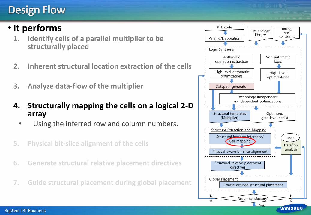
• It performs 1. Identify cells of a parallel multiplier to be
structurally placed
2. Inherent structural location extraction of the cells
3. Analyze data-flow of the multiplier
4. Structurally mapping the cells on a logical 2-D array
• Using the inferred row and column numbers.
5. Physical bit-slice alignment of the cells
6. Generate structural relative placement directives
7. Guide structural placement during global placement
Technology independent and dependent optimizations
RTL code
Datapath generator
Logic Synthesis
Physical aware bit-slice alignment
Optimized gate-level netlist
Structural templates (Multiplier)
Parsing/Elaboration
Arithmetic operation extraction
High-level arithmetic optimizations
Non-arithmetic logic
Dataflow analysis
High-level optimizations
Result satisfactory?
Structure Extraction and Mapping
User
Technology
library
Timing/ Area
constraints
Structural location inference/ Cell mapping
No
No
Yes
Coarse-grained structural placement
Structural relative placement directives
Global Placement
• The PI cells are mapped onto a logical 2-D array according to their tagged row and column numbers.
• However, the number of cells inferring to the same location can be uneven due to the local nature of logic synthesis optimizations.
• If enough slots are allocated for all the cells, the 2-D array may have uncontrollable aspect ratio which may degrade placement quality.
• The maximum number of columns is constrained to control the array dimension. • The number of rows is fixed.
• Some mis-mappings are allowed. • Slot sharing between adjacent columns.
• There are spacing between the rows of the 2-D array. • Non-guided cells to be placed close to their inherent structural locations.
15
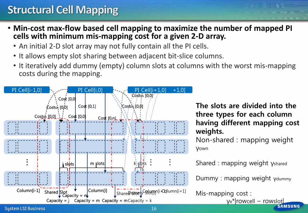
• Min-cost max-flow based cell mapping to maximize the number of mapped PI cells with minimum mis-mapping cost for a given 2-D array. • An initial 2-D slot array may not fully contain all the PI cells. • It allows empty slot sharing between adjacent bit-slice columns. • It iteratively add dummy (empty) column slots at columns with the worst mis-mapping
costs during the mapping.
16
Column[i]
PI Cell[i,0]
Cost [0,0]
Cost [0,1]
Cost [0,n]
m slots
Column[i-1] Column[i+1]
PI Cell[i-1,0] PI Cell[i+1,0]
Capacity = m Capacity = m Capacity = m
Dummy Slot[i]
k slots
Cost [0,0]
CostSH [0,0]
CostDS [0,0]
Capacity = j
j slots
Shared Slot
Capacity = k
CostSH [0,0]
CostDS [0,0]
The slots are divided into the three types for each column having different mapping cost weights. Non-shared : mapping weight γown
Shared : mapping weight γshared
Dummy : mapping weight γdummy
Mis-mapping cost : γx*|rowcell – rowslot|
Column[i]
PI Cell[i,0]
Cost [0,0]
Cost [0,1]
Cost [0,n]
m slots
Column[i-1] Column[i+1]
PI Cell[i-1,0] PI Cell[i+1,0]
Capacity = m Capacity = m Capacity = m
Cost [0,0]
CostSH [0,0]
CostDS [0,0]
Capacity = j
j slots
Shared Slot
CostSH [0,0]
CostDS [0,0]
Shared Slot
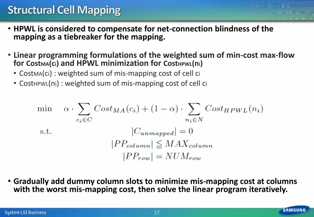
• HPWL is considered to compensate for net-connection blindness of the mapping as a tiebreaker for the mapping.
• Linear programming formulations of the weighted sum of min-cost max-flow for CostMA(ci) and HPWL minimization for CostHPWL(ni) • CostMA(ci) : weighted sum of mis-mapping cost of cell ci
• CostHPWL(ni) : weighted sum of mis-mapping cost of cell ci
• Gradually add dummy column slots to minimize mis-mapping cost at columns with the worst mis-mapping cost, then solve the linear program iteratively.
17
• It performs 1. Identify cells of a parallel multiplier to be
structurally placed
2. Inherent structural location extraction of the cells
3. Analyze data-flow of the multiplier
4. Structurally mapping the cells on a logical 2-D array
5. Physical bit-slice alignment of the cells
6. Generate structural relative placement directives
7. Guide structural placement during global placement
Technology independent and dependent optimizations
RTL code
Datapath generator
Logic Synthesis
Physical aware bit-slice alignment
Optimized gate-level netlist
Structural templates (Multiplier)
Parsing/Elaboration
Arithmetic operation extraction
High-level arithmetic optimizations
Non-arithmetic logic
Dataflow analysis
High-level optimizations
Result satisfactory?
Structure Extraction and Mapping
User
Technology
library
Timing/ Area
constraints
Structural location inference/ Cell mapping
No
No
Yes
Coarse-grained structural placement
Structural relative placement directives
Global Placement
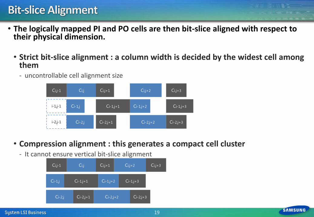
• The logically mapped PI and PO cells are then bit-slice aligned with respect to their physical dimension. • Strict bit-slice alignment : a column width is decided by the widest cell among
them - uncontrollable cell alignment size
• Compression alignment : this generates a compact cell cluster - It cannot ensure vertical bit-slice alignment
19
Ci,j+2
Ci-1,j+2
Ci-2,j+2
Ci,j+3
Ci-1,j+3
Ci-2,j+3
Ci,j Ci,j+1
Ci-1,j Ci-1,j+1
Ci,j-1
Ci-2,j Ci-2,j+1
i-1,j-1
i-2,j-1
Ci,j+2
Ci-1,j+2
Ci-2,j+2
Ci,j+3
Ci-1,j+3
Ci-2,j+3
Ci,j Ci,j+1
Ci-1,j Ci-1,j+1
Ci,j-1
Ci-2,j Ci-2,j+1
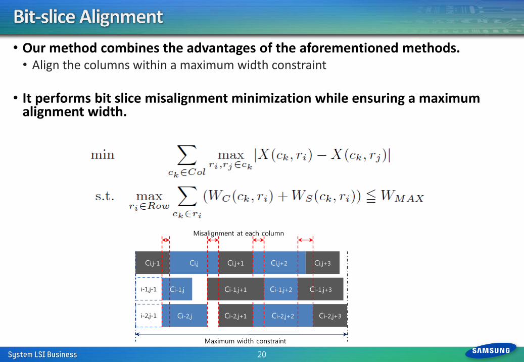
• Our method combines the advantages of the aforementioned methods. • Align the columns within a maximum width constraint
• It performs bit slice misalignment minimization while ensuring a maximum alignment width.
20
Ci,j+2
Ci-1,j+2
Ci-2,j+2
Ci,j+3
Ci-1,j+3
Ci-2,j+3
Ci,j Ci,j+1
Ci-1,j Ci-1,j+1
Ci,j-1
Ci-2,j Ci-2,j+1
i-1,j-1
i-2,j-1
Maximum width constraint
Misalignment at each column
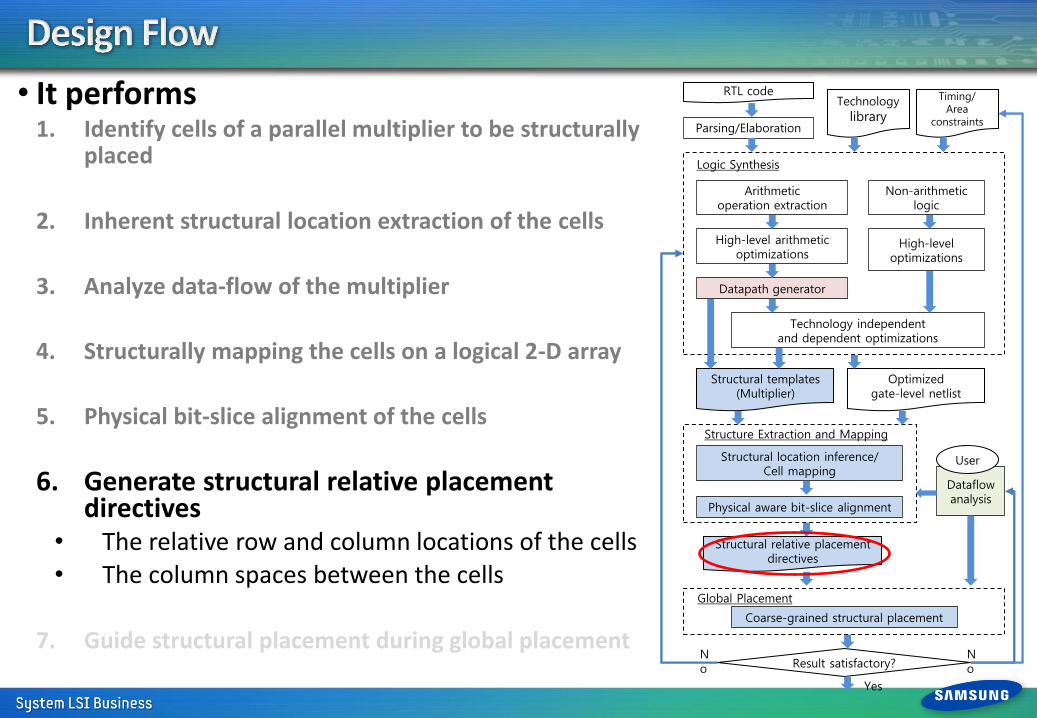
• It performs 1. Identify cells of a parallel multiplier to be structurally
placed
2. Inherent structural location extraction of the cells
3. Analyze data-flow of the multiplier
4. Structurally mapping the cells on a logical 2-D array
5. Physical bit-slice alignment of the cells
6. Generate structural relative placement directives
• The relative row and column locations of the cells • The column spaces between the cells
7. Guide structural placement during global placement
Technology independent and dependent optimizations
RTL code
Datapath generator
Logic Synthesis
Physical aware bit-slice alignment
Optimized gate-level netlist
Structural templates (Multiplier)
Parsing/Elaboration
Arithmetic operation extraction
High-level arithmetic optimizations
Non-arithmetic logic
Dataflow analysis
High-level optimizations
Result satisfactory?
Structure Extraction and Mapping
User
Technology
library
Timing/ Area
constraints
Structural location inference/ Cell mapping
No
No
Yes
Coarse-grained structural placement
Structural relative placement directives
Global Placement
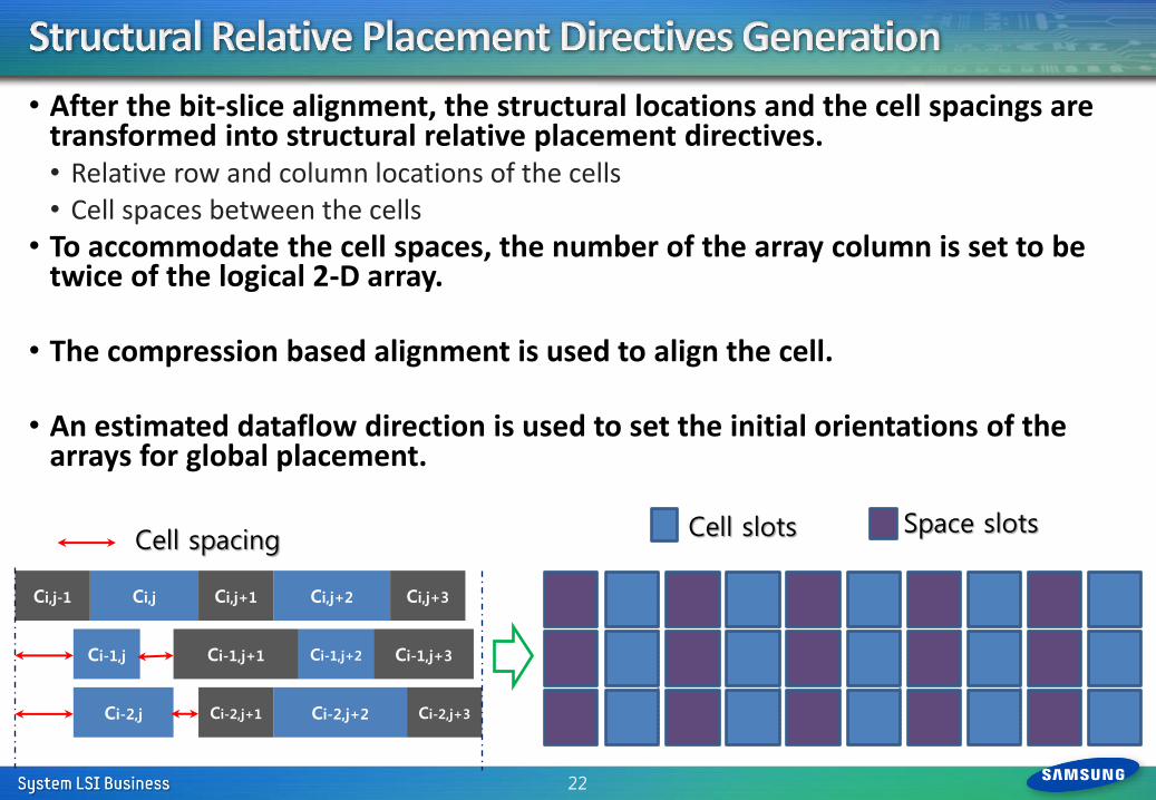
• After the bit-slice alignment, the structural locations and the cell spacings are transformed into structural relative placement directives. • Relative row and column locations of the cells • Cell spaces between the cells
• To accommodate the cell spaces, the number of the array column is set to be twice of the logical 2-D array.
• The compression based alignment is used to align the cell.
• An estimated dataflow direction is used to set the initial orientations of the arrays for global placement.
22
Ci,j+2
Ci-1,j+2
Ci-2,j+2
Ci,j+3
Ci-1,j+3
Ci-2,j+3
Ci,j Ci,j+1
Ci-1,j Ci-1,j+1
Ci,j-1
Ci-2,j Ci-2,j+1
Cell spacing Cell slots Space slots
• It performs 1. Identify cells of a parallel multiplier to be
structurally placed
2. Inherent structural location extraction of the cells
3. Analyze data-flow of the multiplier
4. Structurally mapping the cells on a logical 2-D array
5. Physical bit-slice alignment of the cells
6. Generate structural relative placement directives
7. Guide structural placement during global placement
Technology independent and dependent optimizations
RTL code
Datapath generator
Logic Synthesis
Physical aware bit-slice alignment
Optimized gate-level netlist
Structural templates (Multiplier)
Parsing/Elaboration
Arithmetic operation extraction
High-level arithmetic optimizations
Non-arithmetic logic
Dataflow analysis
High-level optimizations
Result satisfactory?
Structure Extraction and Mapping
User
Technology
library
Timing/ Area
constraints
Structural location inference/ Cell mapping
No
No
Yes
Coarse-grained structural placement
Structural relative placement directives
Global Placement

• Structural relative placement directives hold the locations of the PI and PO cells.
• Non-guided cells are attracted to the PI and PO cells.
24
13*12 non-Booth multiplier 32*16 Booth multiplier
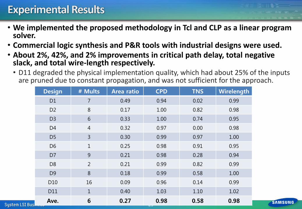
• We implemented the proposed methodology in Tcl and CLP as a linear program solver.
• Commercial logic synthesis and P&R tools with industrial designs were used. • About 2%, 42%, and 2% improvements in critical path delay, total negative
slack, and total wire-length respectively. • D11 degraded the physical implementation quality, which had about 25% of the inputs
are pruned due to constant propagation, and was not sufficient for the approach.
25
Design # Mults Area ratio CPD TNS Wirelength
D1 7 0.49 0.94 0.02 0.99
D2 8 0.17 1.00 0.82 0.98
D3 6 0.33 1.00 0.74 0.95
D4 4 0.32 0.97 0.00 0.98
D5 3 0.30 0.99 0.97 1.00
D6 1 0.25 0.98 0.91 0.95
D7 9 0.21 0.98 0.28 0.94
D8 2 0.21 0.99 0.82 0.99
D9 8 0.18 0.99 0.58 1.00
D10 16 0.09 0.96 0.14 0.99
D11 1 0.40 1.03 1.10 1.02
Ave. 6 0.27 0.98 0.58 0.98
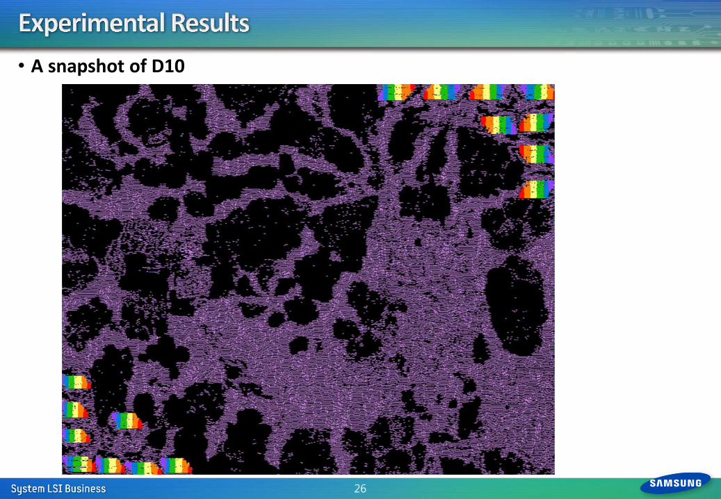
• A snapshot of D10
26
• The future works will focus on • Extending the methodology for other synthesized datapath circuits.
• Developing regularity measuring methods to avoid structurally mapping
insufficiently regular multipliers. • Adding more surround awareness to further automate the methodology.
27