Embed Size (px)
Citation preview

Sun Microsystems, Inc.www.sun.com
Submit comments about this document at: http://www.sun.com/hwdocs/feedback
Sun StorageTek™ Dual 4 Gb FCDual GbE HBA Installation Guide
For HBA Model SG-XPCIE2FCGBE-Q-Z
Part No. 820-3783-11June 2008, Revision A

Copyright © 2008 Sun Microsystems, Inc., 4150 Network Circle, Santa Clara, California 95054, U.S.A. All rights reserved.
U.S. Government Rights - Commercial software. Government users are subject to the Sun Microsystems, Inc. standard license agreement andapplicable provisions of the FAR and its supplements.
Use is subject to license terms.
This distribution may include materials developed by third parties.
Parts of the product may be derived from Berkeley BSD systems, licensed from the University of California. UNIX is a registered trademark inthe U.S. and in other countries, exclusively licensed through X/Open Company, Ltd.
Sun, Sun Microsystems, the Sun logo, Netra, Solaris, Sun Ray, Sun StorEdge, Sun StorageTek, UNIX, Sun Blade, SunVTS, and SunSolve aretrademarks or registered trademarks of Sun Microsystems, Inc. in the U.S. and other countries.
All SPARC trademarks are used under license and are trademarks or registered trademarks of SPARC International, Inc. in the U.S. and othercountries. Products bearing SPARC trademarks are based upon architecture developed by Sun Microsystems, Inc.
ExpressModule™.
This product is covered and controlled by U.S. Export Control laws and may be subject to the export or import laws in other countries. Nuclear,missile, chemical biological weapons or nuclear maritime end uses or end users, whether direct or indirect, are strictly prohibited. Export orreexport to countries subject to U.S. embargo or to entities identified on U.S. export exclusion lists, including, but not limited to, the deniedpersons and specially designated nationals lists is strictly prohibited.
DOCUMENTATION IS PROVIDED "AS IS" AND ALL EXPRESS OR IMPLIED CONDITIONS, REPRESENTATIONS AND WARRANTIES,INCLUDING ANY IMPLIED WARRANTY OF MERCHANTABILITY, FITNESS FOR A PARTICULAR PURPOSE OR NON-INFRINGEMENT,ARE DISCLAIMED, EXCEPT TO THE EXTENT THAT SUCH DISCLAIMERS ARE HELD TO BE LEGALLY INVALID.
Copyright © 2008 Sun Microsystems, Inc., 4150 Network Circle, Santa Clara, California 95054, Etats-Unis. Tous droits réservés.
L'utilisation est soumise aux termes de la Licence.
Cette distribution peut comprendre des composants développés par des tierces parties.
Des parties de ce produit pourront être dérivées des systèmes Berkeley BSD licenciés par l'Université de Californie. UNIX est une marquedéposée aux Etats-Unis et dans d'autres pays et licenciée exclusivement par X/Open Company, Ltd.
Sun, Sun Microsystems, le logo Sun, Netra, Solaris, Sun Ray, Sun StorEdge, Sun StorageTek, UNIX, Sun Blade, SunVTS, et SunSolve sont desmarques de fabrique ou des marques déposées de Sun Microsystems, Inc. aux Etats-Unis et dans d'autres pays.
Toutes les marques SPARC sont utilisées sous licence et sont des marques de fabrique ou des marques déposées de SPARC International, Inc.aux Etats-Unis et dans d'autres pays. Les produits portant les marques SPARC sont basés sur une architecture développée par SunMicrosystems, Inc.
ExpressModule™.
Ce produit est soumis à la législation américaine en matière de contrôle des exportations et peut être soumis à la règlementation en vigueurdans d'autres pays dans le domaine des exportations et importations. Les utilisations, ou utilisateurs finaux, pour des armes nucléaires,desmissiles, des armes biologiques et chimiques ou du nucléaire maritime, directement ou indirectement, sont strictement interdites. Lesexportations ou réexportations vers les pays sous embargo américain, ou vers des entités figurant sur les listes d'exclusion d'exportationaméricaines, y compris, mais de manière non exhaustive, la liste de personnes qui font objet d'un ordre de ne pas participer, d'une façon directeou indirecte, aux exportations des produits ou des services qui sont régis par la législation américaine en matière de contrôle des exportations etla liste de ressortissants spécifiquement désignés, sont rigoureusement interdites.
LA DOCUMENTATION EST FOURNIE "EN L’ÉTAT" ET TOUTES AUTRES CONDITIONS, DECLARATIONS ET GARANTIES EXPRESSESOU TACITES SONT FORMELLEMENT EXCLUES, DANS LA MESURE AUTORISEE PAR LA LOI APPLICABLE, Y COMPRIS NOTAMMENTTOUTE GARANTIE IMPLICITE RELATIVE A LA QUALITE MARCHANDE, A L’APTITUDE A UNE UTILISATION PARTICULIERE OU AL’ABSENCE DE CONTREFAÇON.
Contents
Declaration of Conformity vii
Safety Agency Compliance Statements ix
Regulatory Compliance Statements xxi
Preface xxiii
1. HBA Overview 1
Kit Contents 1
HBA Features and Specifications 1
Operating System and Technology Requirements 3
System Interoperability 4
Host Platform Support 4
Storage Support 5
Array Support 5
Tape Storage Support 5
Switch Support 6
Software Support 7
Environmental Requirements 7
2. Hardware Installation and Removal 9
iii

Observing ESD and Handling Precautions 9
Installing the Hardware 10
▼ To Install the HBA 10
▼ To Connect the HBA 11
▼ To Power On the HBA 12
LED Descriptions and Status 13
LED and Switch Locations 13
Fibre Channel LED Indicator Status 15
Ethernet LED Indicator Status 15
Power and Attention Switch LED Scheme 16
Configuring the HBA For Hot-Plug Operation 16
Testing the Installation 17
▼ To Test the Installation for the Solaris OS 17
▼ To Test the Installation for the Windows OS 17
▼ To Test the Installation for the VMware Technology 18
Removing the Hardware 18
▼ To Prepare the HBA for Removal Using the HBA Attention Button 18
▼ To Prepare the HBA for Hot-Plug Removal (Using the Solaris OS) 19
▼ To Remove the HBA 19
3. Software Installation 21
Installing Software for the Solaris OS 21
Installing the Fibre Channel Driver 21
▼ To Install or Update the qlc HBA Driver From a Patch 22
Installing the Ethernet Driver 22
Diagnostic Support for the Solaris OS 22
Installing Software for the Red Hat/SUSE Linux OS 23
Downloading the Red Hat/SUSE Linux Drivers 23
▼ To Download the Fibre Channel Driver 23
iv Sun StorageTek Dual 4 Gb FC Dual GbE HBA Installation Guide • June 2008

▼ To Download the Ethernet Driver 24
Installing the Red Hat/SUSE Linux Drivers 24
▼ To Build the Fibre Channel Driver 24
▼ To Load the Newly Built Fibre Channel Driver 25
▼ To Build and Load the Ethernet HBA Driver 27
Diagnostic Support for the Red Hat/SUSE OS 28
▼ To Install Diagnostic Support for the Red Hat/SUSE Linux OS 28
Installing Software for the VMware Technology 28
Installing Software for the Windows OS 29
▼ To Download the Fibre Channel Driver 29
▼ To Install the Fibre Channel Driver 30
▼ To Download and Install the Ethernet Driver 30
Diagnostic Support for the Windows OS 31
▼ To Install Diagnostic Support for the Windows OS 31
Installing a CLI for Updating the BIOS and FCode 32
4. Known Issues 33
Server Compatibility Issues 33
Cannot Set the HBA to a Configured State on a Sun Blade X6250 Server (6674189)33
The HBA is Not Detected on a Sun Blade T6320 Server ( 6682447) 34
qlc Driver Issues 34
The fcinfo Command Displays Inconsistent Information About the HBA(6683551) 34
No Support For N-Port, Point-to-Point Topology (6547693) 34
Red Hat Linux Enterprise Issues 35
Error Messages Are Displayed in System Log Files When Running the RHEL 5 OS35
Contents v

vi Sun StorageTek Dual 4 Gb FC Dual GbE HBA Installation Guide • June 2008
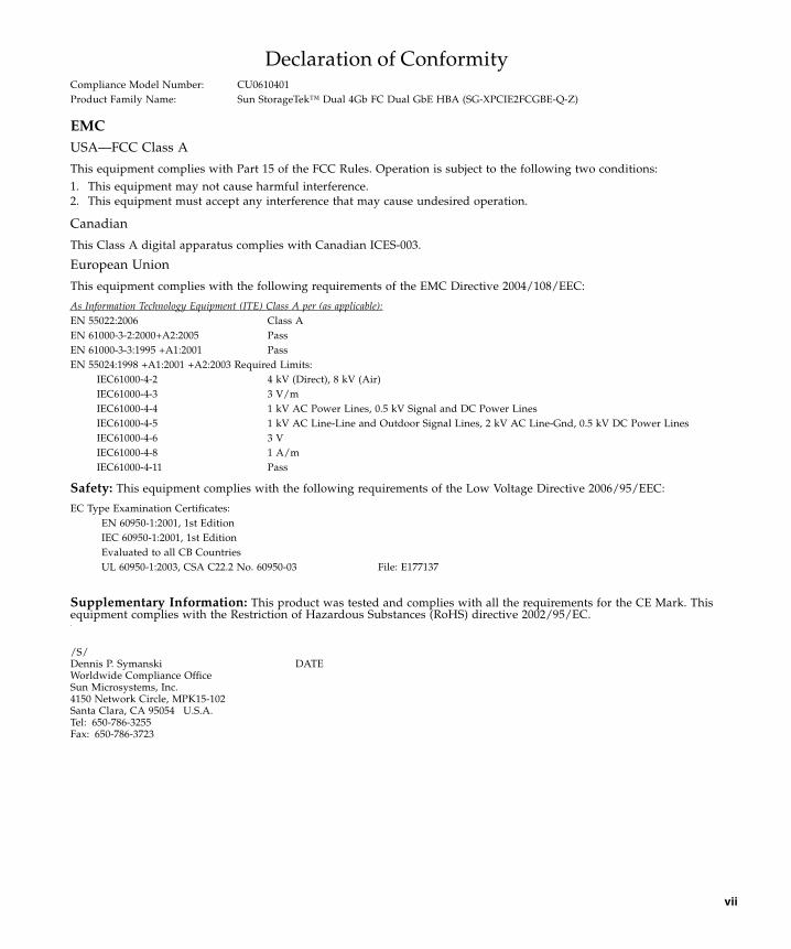
Declaration of Conformity
EMCUSA—FCC Class A
This equipment complies with Part 15 of the FCC Rules. Operation is subject to the following two conditions:1. This equipment may not cause harmful interference.2. This equipment must accept any interference that may cause undesired operation.
Canadian
This Class A digital apparatus complies with Canadian ICES-003.
European Union
This equipment complies with the following requirements of the EMC Directive 2004/108/EEC:
Safety: This equipment complies with the following requirements of the Low Voltage Directive 2006/95/EEC:
Supplementary Information: This product was tested and complies with all the requirements for the CE Mark. Thisequipment complies with the Restriction of Hazardous Substances (RoHS) directive 2002/95/EC..
Compliance Model Number: CU0610401Product Family Name: Sun StorageTek™ Dual 4Gb FC Dual GbE HBA (SG-XPCIE2FCGBE-Q-Z)
As Information Technology Equipment (ITE) Class A per (as applicable):EN 55022:2006 Class AEN 61000-3-2:2000+A2:2005 PassEN 61000-3-3:1995 +A1:2001 PassEN 55024:1998 +A1:2001 +A2:2003 Required Limits:
IEC61000-4-2 4 kV (Direct), 8 kV (Air)IEC61000-4-3 3 V/mIEC61000-4-4 1 kV AC Power Lines, 0.5 kV Signal and DC Power LinesIEC61000-4-5 1 kV AC Line-Line and Outdoor Signal Lines, 2 kV AC Line-Gnd, 0.5 kV DC Power LinesIEC61000-4-6 3 VIEC61000-4-8 1 A/mIEC61000-4-11 Pass
EC Type Examination Certificates:EN 60950-1:2001, 1st EditionIEC 60950-1:2001, 1st EditionEvaluated to all CB CountriesUL 60950-1:2003, CSA C22.2 No. 60950-03 File: E177137
/S/Dennis P. Symanski DATEWorldwide Compliance OfficeSun Microsystems, Inc.4150 Network Circle, MPK15-102Santa Clara, CA 95054 U.S.A.Tel: 650-786-3255Fax: 650-786-3723
vii

viii Sun StorageTek Dual 4 Gb FC Dual GbE HBA Installation Guide • June 2008
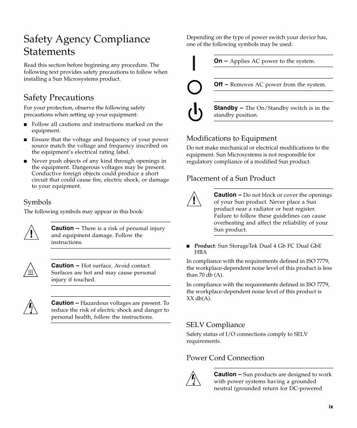
Safety Agency ComplianceStatementsRead this section before beginning any procedure. Thefollowing text provides safety precautions to follow wheninstalling a Sun Microsystems product.
Safety PrecautionsFor your protection, observe the following safetyprecautions when setting up your equipment:
■ Follow all cautions and instructions marked on theequipment.
■ Ensure that the voltage and frequency of your powersource match the voltage and frequency inscribed onthe equipment’s electrical rating label.
■ Never push objects of any kind through openings inthe equipment. Dangerous voltages may be present.Conductive foreign objects could produce a shortcircuit that could cause fire, electric shock, or damageto your equipment.
SymbolsThe following symbols may appear in this book:
Caution – There is a risk of personal injuryand equipment damage. Follow theinstructions.
Caution – Hot surface. Avoid contact.Surfaces are hot and may cause personalinjury if touched.
Caution – Hazardous voltages are present. Toreduce the risk of electric shock and danger topersonal health, follow the instructions.
Depending on the type of power switch your device has,one of the following symbols may be used:
On – Applies AC power to the system.
Off – Removes AC power from the system.
Standby – The On/Standby switch is in thestandby position.
Modifications to EquipmentDo not make mechanical or electrical modifications to theequipment. Sun Microsystems is not responsible forregulatory compliance of a modified Sun product.
Placement of a Sun Product
Caution – Do not block or cover the openingsof your Sun product. Never place a Sunproduct near a radiator or heat register.Failure to follow these guidelines can causeoverheating and affect the reliability of yourSun product.
■ Product: Sun StorageTek Dual 4 Gb FC Dual GbEHBA
In compliance with the requirements defined in ISO 7779,the workplace-dependent noise level of this product is lessthan 70 db (A).
In compliance with the requirements defined in ISO 7779,the workplace-dependent noise level of this product isXX db(A).
SELV ComplianceSafety status of I/O connections comply to SELVrequirements.
Power Cord Connection
Caution – Sun products are designed to workwith power systems having a groundedneutral (grounded return for DC-powered
ix
products). To reduce the risk of electric shock,do not plug Sun products into any other typeof power system. Contact your facilitiesmanager or a qualified electrician if you arenot sure what type of power is supplied toyour building.
Caution – Not all power cords have the samecurrent ratings. Do not use the power cordprovided with your equipment for any otherproducts or use. Household extension cordsdo not have overload protection and are notmeant for use with computer systems. Do notuse household extension cords with your Sunproduct.
The following caution applies only to devices with aStandby power switch:
Caution – The power switch of this productfunctions as a standby type device only. Thepower cord serves as the primary disconnectdevice for the system. Be sure to plug thepower cord into a grounded power outlet thatis nearby the system and is readily accessible.Do not connect the power cord when thepower supply has been removed from thesystem chassis.
The following caution applies only to devices with multiplepower cords:
Caution – For products with multiple powercords, all power cords must be disconnectedto completely remove power from the system.
Battery Warning
Caution – There is danger of explosion ifbatteries are mishandled or incorrectlyreplaced. On systems with replaceablebatteries, replace only with the samemanufacturer and type or equivalent typerecommended by the manufacturer per theinstructions provided in the product servicemanual. Do not disassemble batteries orattempt to recharge them outside the system.Do not dispose of batteries in fire. Dispose ofbatteries properly in accordance with themanufacturer’s instructions and localregulations. Note that on Sun CPU boards,there is a lithium battery molded into the real-time clock. These batteries are not customerreplaceable parts.
x Sun StorageTek Dual 4 Gb FC Dual GbE HBA Installation Guide • June 2008
System Unit CoverYou must remove the cover of your Sun computer systemunit to add cards, memory, or internal storage devices. Besure to replace the cover before powering on your computersystem.
Caution – Do not operate Sun productswithout the cover in place. Failure to take thisprecaution may result in personal injury andsystem damage.
Rack System WarningThe following warnings apply to Racks and Rack Mountedsystems.
Caution – For safety, equipment shouldalways be loaded from the bottom up. That is,install the equipment that will be mounted inthe lowest part of the rack first, then the nexthigher systems, etc.
Caution – To prevent the rack from tippingduring equipment installation, the anti-tilt baron the rack must be deployed.
Caution – To prevent extreme operatingtemperature within the rack insure that themaximum temperature does not exceed theproduct’s ambient rated temperatures.
Caution – To prevent extreme operatingtemperatures due to reduced airflowconsideration should be made to the amountof air flow that is required for a safe operationof the equipment.
Laser Compliance NoticeSun products that use laser technology comply with Class 1laser requirements.
CD and DVD DevicesThe following caution applies to CD, DVD, and otheroptical devices.
Caution – Use of controls, adjustments, orthe performance of procedures other thanthose specified herein may result in hazardousradiation exposure.
Conformité aux normes de sécuritéVeuillez lire attentivement cette section avant decommencer. Ce texte traite des mesures de sécurité qu’ilconvient de prendre pour l’installation d’un produit SunMicrosystems.
Mesures de sécuritéPour votre sécurité, nous vous recommandons de suivrescrupuleusement les mesures de sécurité ci-dessous lorsquevous installez votre matériel:
■ Suivez tous les avertissements et toutes lesinstructions inscrites sur le matériel.
■ Assurez-vous que la tension et la fréquence de votresource d'alimentation correspondent à la tension et àla fréquence indiquées sur l'étiquette de la tensionélectrique nominale du matériel
■ N'introduisez jamais d'objets quels qu'ils soient dansles ouvertures de l'équipement. Vous pourriez voustrouver en présence de hautes tensions dangereuses.Tout objet étranger conducteur risque de produire uncourt-circuit pouvant présenter un risque d'incendieou de décharge électrique, ou susceptibled'endommager le matériel.
Class 1 Laser ProductLuokan 1 Laserlaite
Klasse 1 Laser ApparatLaser Klasse 1
Safety Agency Compliance Statements xi

SymbolesVous trouverez ci-dessous la signification des différentssymboles utilisés:
Attention – Vous risquez d'endommager lematériel ou de vous blesser. Veuillez suivre lesinstructions.
Attention – Surfaces brûlantes. Evitez toutcontact. Les surfaces sont brûlantes. Vousrisquez de vous blesser si vous les touchez.
Attention – Tensions dangereuses. Pourréduire les risques de décharge électrique etde danger physique, observez les consignesindiquées.
Selon le type d'interrupteur marche/arrêt dont votreappareil est équipé, l'un des symboles suivants sera utilisé:
Marche – Met le système sous tensionalternative.
Arret – Met le système hors tensionalternative.
Veilleuse – L'interrupteur Marche/Veille estsur la position de veille.
Modification du matérielN'apportez aucune modification mécanique ou électriqueau matériel. Sun Microsystems décline toute responsabilitéquant à la non-conformité éventuelle d'un produit Sunmodifié.
Positionnement d’un produit Sun
Attention – Evitez d'obstruer ou de recouvrirles orifices de votre produit Sun. N'installezjamais un produit Sun près d'un radiateur oud'une source de chaleur. Si vous ne respectezpas ces consignes, votre produit Sun risque desurchauffer et son fonctionnement en seraaltéré.
Niveau de pression acoustiqueProduit : Sun StorageTek Dual 4 Gb FC Dual GbE HBA
Conformément à la norme ISO 7779, le niveau sonore de ceproduit sur le lieu de travail est inférieur à 70 db(A).
Conformément à la norme ISO 7779, le niveau sonore de ceproduit sur le lieu de travail est de XX db(A).
Conformité SELVLe niveau de sécurité des connexions E/S est conforme auxnormes SELV.
Connexion du cordon d’alimentation
Attention – Les produits Sun sont conçuspour fonctionner avec des systèmesd'alimentation équipés d'un conducteurneutre relié à la terre (conducteur neutre pourproduits alimentés en CC). Pour réduire lesrisques de décharge électrique, ne branchezjamais les produits Sun sur une sourced'alimentation d'un autre type. Contactez legérant de votre bâtiment ou un électricienagréé si vous avez le moindre doute quant autype d'alimentation fourni dans votrebâtiment.
Attention – Tous les cordons d'alimentationne présentent pas les mêmes caractéristiquesélectriques. Les cordons d'alimentation àusage domestique ne sont pas protégés contreles surtensions et ne sont pas conçus pour êtreutilisés avec des ordinateurs. N'utilisez jamaisde cordon d'alimentation à usage domestiqueavec les produits Sun.
xii Sun StorageTek Dual 4 Gb FC Dual GbE HBA Installation Guide • June 2008

L'avertissement suivant s'applique uniquement auxsystèmes équipés d'un interrupteur Veille:
Attention – L'interrupteur d'alimentation dece produit fonctionne uniquement comme undispositif de mise en veille. Le cordond'alimentation constitue le moyen principal dedéconnexion de l'alimentation pour lesystème. Assurez-vous de le brancher dansune prise d'alimentation mise à la terre prèsdu système et facile d'accès. Ne le branchezpas lorsque l'alimentation électrique ne setrouve pas dans le châssis du système.
L'avertissement suivant s'applique uniquement auxsystèmes équipés de plusieurs cordons d'alimentation:
Attention – Pour mettre un système équipéde plusieurs cordons d'alimentation horstension, il est nécessaire de débrancher tousles cordons d'alimentation.
Mise en garde relative aux batteries
Attention – Les batteries risquent d’exploseren cas de manipulation maladroite ou deremplacement incorrect. Pour les systèmesdont les batteries sont remplaçables, effectuezles remplacements uniquement selon lemodèle du fabricant ou un modèle équivalentrecommandé par le fabricant, conformémentaux instructions fournies dans le manuel deservice du système. N’essayez en aucun cas dedémonter les batteries, ni de les recharger horsdu système. Ne les jetez pas au feu. Mettez-lesau rebut selon les instructions du fabricant etconformément à la législation locale envigueur. Notez que sur les cartes processeurde Sun, une batterie au lithium a été mouléedans l'horloge temps réel. Les batteries ne sontpas des pièces remplaçables par le client.
Couvercle de l'unitéPour ajouter des cartes, de la mémoire ou des périphériquesde stockage internes, vous devez retirer le couvercle de
votre système Sun. Remettez le couvercle supérieur enplace avant de mettre votre système sous tension.
Attention – Ne mettez jamais des produitsSun sous tension si leur couvercle supérieurn'est pas mis en place. Si vous ne prenez pasces précautions, vous risquez de vous blesserou d'endommager le système.
Mise en garde relative au système en rackLa mise en garde suivante s'applique aux racks et auxsystèmes montés en rack.
Attention – Pour des raisons de sécurité, lematériel doit toujours être chargé du bas versle haut. En d'autres termes, vous devezinstaller, en premier, le matériel qui doit setrouver dans la partie la plus inférieure durack, puis installer le matériel sur le niveausuivant, etc.
Attention – Afin d'éviter que le rack nepenche pendant l'installation du matériel, tirezla barre anti-basculement du rack.
Attention – Pour éviter des températures defonctionnement extrêmes dans le rack,assurez-vous que la température maximale nedépasse pas la fourchette de températuresambiantes du produit déterminée par lefabricant.
Attention – Afin d'empêcher destempératures de fonctionnement extrêmesprovoquées par une aération insuffisante,assurez-vous de fournir une aérationappropriée pour un fonctionnement dumatériel en toute sécurité
Avis de conformité des appareils laserLes produits Sun qui font appel aux technologies lasers sontconformes aux normes de la classe 1 en la matière.
Safety Agency Compliance Statements xiii

Périphériques CD et DVDL'avertissement suivant s'applique aux périphériques CD,DVD et autres périphériques optiques:
Attention – L'utilisation de contrôles et deréglages ou l'application de procédures autresque ceux spécifiés dans le présent documentpeuvent entraîner une exposition à desradiations dangereuses.
Einhaltung sicherheitsbehördlicherVorschriftenLesen Sie vor dem Ausführen von Arbeiten diesenAbschnitt. Im folgenden Text werden Sicherheitsvor-kehrungen beschrieben, die Sie bei der Installation einesSun Microsystems-Produkts beachten müssen.
SicherheitsvorkehrungenTreffen Sie zu Ihrem eigenen Schutz bei der Installation desGeräts die folgenden Sicherheitsvorkehrungen:
■ Beachten Sie alle auf den Geräten angebrachtenWarnhinweise und Anweisungen.
■ Stellen Sie sicher, dass Spannung und Frequenz derStromversorgung den Nennleistungen auf dem amGerät angebrachten Etikett entsprechen.
■ Führen Sie niemals Fremdobjekte in die Öffnungenam Gerät ein. Es können gefährliche Spannungenanliegen. Leitfähige Fremdobjekte können einenKurzschluss verursachen, der einen Brand, Strom-schlag oder Geräteschaden herbeiführen kann.
SymboleDie Symbole in diesem Handbuch haben folgendeBedeutung:
Achtung – Gefahr von Verletzung undGeräteschaden. Befolgen Sie die Anwei-sungen.
Achtung – Heiße Oberfläche. Nicht berühren,da Verletzungsgefahr durch heiße Oberflächebesteht.
Achtung – Gefährliche Spannungen.Befolgen Sie die Anweisungen, umStromschläge und Verletzungen zu vermeiden.
Je nach Netzschaltertyp an Ihrem Gerät kann eines derfolgenden Symbole verwendet werden:
Ein – Versorgt das System mit Wechselstrom.
Aus– Unterbricht die Wechselstromzufuhrzum Gerät.
Wartezustand – Der Ein-/Standby-Netz-schalter befindet sich in der Standby-Position.
Modifikationen des GerätsNehmen Sie keine elektrischen oder mechanischenGerätemodifikationen vor. Sun Microsystems ist für dieEinhaltung der Sicherheitsvorschriften von modifiziertenSun-Produkten nicht haftbar.
Aufstellung von Sun-Geräten
Achtung – Geräteöffnungen Ihres Sun-Produkts dürfen nicht blockiert oderabgedeckt werden. Sun-Geräte sollten niemalsin der Nähe von Heizkörpern oder Heißluft-klappen aufgestellt werden. Die Nichtbeach-tung dieser Richtlinien kann Überhitzungverursachen und die Zuverlässigkeit IhresSun-Geräts beeinträchtigen.
Class 1 Laser ProductLuokan 1 Laserlaite
Klasse 1 Laser ApparatLaser Klasse 1
xiv Sun StorageTek Dual 4 Gb FC Dual GbE HBA Installation Guide • June 2008
LautstärkeProdukt: Sun StorageTek Dual 4 Gb FC Dual GbE HBA
Gemäß den Vorgaben in der Norm ISO 7779 beträgt derGeräuschpegel dieses Geräts in Abhängigkeit vomArbeitsplatz unter 70 db(A).
Gemäß den Vorgaben in der Norm ISO 7779 beträgt derGeräuschpegel dieses Geräts in Abhängigkeit vomArbeitsplatz XX db(A).
SELV-KonformitätDer Sicherheitsstatus der E/A-Verbindungen entsprichtden SELV-Anforderungen.
Anschluss des Netzkabels
Achtung – Sun-Geräte sind fürStromversorgungssysteme mit einemgeerdeten neutralen Leiter (geerdeterRückleiter bei gleichstrombetriebenenGeräten) ausgelegt. Um die Gefahr vonStromschlägen zu vermeiden, schließen Siedas Gerät niemals an andere Stromversor-gungssysteme an. Wenden Sie sich an denzuständigen Gebäudeverwalter oder an einenqualifizierten Elektriker, wenn Sie nicht sicherwissen, an welche Art von Stromversor-gungssystem Ihr Gebäude angeschlossen ist.
Achtung – Nicht alle Netzkabel verfügenüber die gleichen Nennwerte. Herkömmliche,im Haushalt verwendete Verlängerungskabelbesitzen keinen Überlastschutz und sinddaher für Computersysteme nicht geeignet.Verwenden Sie bei Ihrem Sun-Produkt keineHaushalts-Verlängerungskabel.
Die folgende Warnung gilt nur für Geräte mit Standby-Netzschalter:
Achtung – Beim Netzschalter dieses Gerätshandelt es sich nur um einen Ein/Standby-Schalter. Zum völligen Abtrennen des Systemsvon der Stromversorgung dient hauptsächlichdas Netzkabel. Stellen Sie sicher, dass dasNetzkabel an eine frei zugängliche geerdeteSteckdose in der Nähe des Systems ange-
schlossen ist. Schließen Sie das Stromkabelnicht an, wenn die Stromversorgung vomSystemchassis entfernt wurde.
Die folgende Warnung gilt nur für Geräte mit mehrerenNetzkabeln:
Achtung – Bei Produkten mit mehrerenNetz-kabeln müssen alle Netzkabel abgetrenntwer-den, um das System völlig von derStromver-sorgung zu trennen.
Warnung bezüglich Batterien
Achtung – Bei unsachgemäßer Handhabungoder nicht fachgerechtem Austausch derBatterien besteht Explosionsgefahr. Verwen-den Sie bei Systemen mit austauschbarenBatterien ausschließlich Ersatzbatteriendesselben Typs und Herstellers bzw. einenentsprechenden, vom Hersteller gemäß denAnweisungen im Service-Handbuch desProdukts empfohlenen Batterietyp. VersuchenSie nicht, die Batterien auszubauen oderaußerhalb des Systems wiederaufzuladen.Werfen Sie die Batterien nicht ins Feuer.Entsorgen Sie die Batterien entsprechend denAnweisungen des Herstellers und den vor Ortgeltenden Vorschriften. CPU-Karten von Sunverfügen über eine Echtzeituhr mit integrier-ter Lithiumbatterie. Diese Batterie darf nurvon einem qualifizierten Servicetechniker aus-gewechselt werden.
GehäuseabdeckungSie müssen die Abdeckung Ihres Sun-Computersystemsentfernen, um Karten, Speicher oder interne Speichergerätehinzuzufügen. Bringen Sie vor dem Einschalten desSystems die Gehäuseabdeckung wieder an.
Achtung – Nehmen Sie Sun-Geräte nichtohne Abdeckung in Betrieb. DieNichtbeachtung dieses Warnhinweises kannVerletzungen oder Geräteschaden zur Folgehaben.
Safety Agency Compliance Statements xv

Warnungen bezüglich in Racks eingebauterSystemeDie folgenden Warnungen gelten für Racks und in Rackseingebaute Systeme:
Achtung – Aus Sicherheitsgründen solltensämtliche Geräte von unten nach oben inRacks eingebaut werden. Installieren Sie alsozuerst die Geräte, die an der unterstenPosition im Rack eingebaut werden, gefolgtvon den Systemen, die an nächsthöherer Stelleeingebaut werden, usw.
Achtung – Verwenden Sie beim Einbau denKippschutz am Rack, um ein Umkippen zuvermeiden.
Achtung – Um extremeBetriebstemperaturen im Rack zu vermeiden,stellen Sie sicher, dass die Maximaltemperaturdie Nennleistung der Umgebungstemperaturfür das Produkt nicht überschreitet
Achtung – Um extremeBetriebstemperaturen durch verringerteLuftzirkulation zu vermei-den, sollte die fürden sicheren Betrieb des Geräts erforderlicheLuftzirkulation eingesetzt werden.
Hinweis zur Laser-KonformitätSun-Produkte, die die Laser-Technologie verwenden,entsprechen den Laser-Anforderungen der Klasse 1.
CD- und DVD-GeräteDie folgende Warnung gilt für CD-, DVD- und andereoptische Geräte:
Achtung – Die hier nicht aufgeführteVerwendung von Steuerelementen,Anpassungen oder Ausführung vonVorgängen kann eine gefährlicheStrahlenbelastung verursachen.
Normativas de seguridadLea esta sección antes de realizar cualquier operación. Enella se explican las medidas de seguridad que debe tomar alinstalar un producto de Sun Microsystems.
Medidas de seguridadPara su protección, tome las medidas de seguridadsiguientes durante la instalación del equipo:
■ Siga todos los avisos e instrucciones indicados en elequipo.
■ Asegúrese de que el voltaje y frecuencia de la fuentede alimentación coincidan con el voltaje y frecuenciaindicados en la etiqueta de clasificación eléctrica delequipo.
■ No introduzca objetos de ningún tipo por las rejillasdel equipo, ya que puede quedar expuesto a voltajespeligrosos. Los objetos conductores extraños puedenproducir cortocircuitos y, en consecuencia, incendios,descargas eléctricas o daños en el equipo.
SímbolosEn este documento aparecen los siguientes símbolos:
Precaución – Existe el riesgo de que seproduzcan lesiones personales y daños en elequipo. Siga las instrucciones.
Precaución – Superficie caliente. Evite todocontacto. Las superficies están calientes ypueden causar lesiones personales si se tocan.
Class 1 Laser ProductLuokan 1 Laserlaite
Klasse 1 Laser ApparatLaser Klasse 1
xvi Sun StorageTek Dual 4 Gb FC Dual GbE HBA Installation Guide • June 2008
Precaución – Voltaje peligroso. Para reducirel riesgo de descargas eléctricas y lesionespersonales, siga las instrucciones.
En función del tipo de interruptor de alimentación del quedisponga el dispositivo, se utilizará uno de los símbolossiguientes:
Encendido – Suministra alimentación de CAal sistema.
Apagado – Corta la alimentación de CA delsistema.
Espera – El interruptor de encendido/esperaestá en la posición de espera.
Modificaciones en el equipoNo realice modificaciones de tipo mecánico ni eléctrico en elequipo. Sun Microsystems no se hace responsable delcumplimiento de normativas en caso de que un productoSun se haya modificado.
Colocación de un producto Sun
Precaución – No obstruya ni tape las rejillasdel producto Sun. Nunca coloque un productoSun cerca de radiadores ni fuentes de calor. Sino sigue estas indicaciones, el producto Sunpodría sobrecalentarse y la fiabilidad de sufuncionamiento se vería afectada.
Nivel de ruidoProducto: Sun StorageTek Dual 4 Gb FC Dual GbE HBA
En conformidad con la norma ISO 7779, el nivel de emisiónde ruido de este producto en el puesto de trabajo es inferiora los 70 db(A).
En conformidad con la norma ISO 7779, el nivel de emisiónde ruido de este producto en el puesto de trabajo es deXX db(A).
Cumplimiento de la normativa parainstalaciones SELVLas condiciones de seguridad de las conexiones de entraday salida cumplen los requisitos para instalaciones SELV (delinglés Safe Extra Low Voltage, voltaje bajo y seguro).
Conexión del cable de alimentación
Precaución – Los productos Sun se handiseñado para funcionar con sistemas dealimentación que cuenten con un conductorneutro a tierra (con conexión a tierra deregreso para los productos con alimentaciónde CC). Para reducir el riesgo de descargaseléctricas, no conecte ningún producto Sun aotro tipo de sistema de alimentación. Póngaseen contacto con el encargado de lasinstalaciones de su empresa o con unelectricista cualificado en caso de que no estéseguro del tipo de alimentación del que sedispone en el edificio.
Precaución – No todos los cables dealimentación tienen la misma clasificacióneléctrica. Los alargadores de uso doméstico nocuentan con protección frente a sobrecargas yno están diseñados para su utilización consistemas informáticos. No utilice alargadoresde uso doméstico con el producto Sun.
La siguiente medida solamente se aplica a aquellosdispositivos que dispongan de un interruptor dealimentación de espera:
Precaución – El interruptor de alimentaciónde este producto funciona solamente como undispositivo de espera. El cable de alimentaciónhace las veces de dispositivo de desconexiónprincipal del sistema. Asegúrese de queconecta el cable de alimentación a una tomade tierra situada cerca del sistema y de fácilacceso. No conecte el cable de alimentación sila unidad de alimentación no se encuentra enel bastidor del sistema.
Safety Agency Compliance Statements xvii
La siguiente medida solamente se aplica a aquellosdispositivos que dispongan de varios cables dealimentación:
Precaución – En los productos que cuentancon varios cables de alimentación, debedesconectar todos los cables de alimentaciónpara cortar por completo la alimentacióneléctrica del sistema.
Advertencia sobre las baterías
Precaución – Si las baterías no se manipulano reemplazan correctamente, se corre el riesgode que estallen. En los sistemas que cuentancon baterías reemplazables, reemplácelas sólocon baterías del mismo fabricante y el mismotipo, o un tipo equivalente recomendado porel fabricante, de acuerdo con las instruccionesdescritas en el manual de servicio delproducto. No desmonte las baterías ni intenterecargarlas fuera del sistema. No intentedeshacerse de las baterías echándolas al fuego.Deshágase de las baterías correctamente deacuerdo con las instrucciones del fabricante ylas normas locales. Tenga en cuenta que en lasplacas CPU de Sun, hay una batería de litioincorporada en el reloj en tiempo real. Losusuarios no deben reemplazar este tipo debaterías.
Cubierta de la unidad del sistemaDebe extraer la cubierta de la unidad del sistemainformático Sun para instalar tarjetas, memoria odispositivos de almacenamiento internos. Vuelva a colocarla cubierta antes de encender el sistema informático.
Precaución – No ponga en funcionamientolos productos Sun que no tengan colocada lacubierta. De lo contrario, puede sufrir lesionespersonales y ocasionar daños en el sistema.
Advertencia sobre el sistema en bastidorLas advertencias siguientes se aplican a los sistemasmontados en bastidor y a los propios bastidores.
Precaución – Por seguridad, siempre debenmontarse los equipos de abajo arriba. A saber,primero debe instalarse el equipo que sesituará en el bastidor inferior; a continuación,el que se situará en el siguiente nivel, etc.
Precaución – Para evitar que el bastidor sevuelque durante la instalación del equipo,debe extenderse la barra antivolcado delbastidor.
Precaución – Para evitar que se alcance unatemperatura de funcionamiento extrema en elbastidor, asegúrese de que la temperaturamáxima no sea superior a la temperaturaambiente establecida como adecuada para elproducto.
Precaución – Para evitar que se alcance unatemperatura de funcionamiento extremadebido a una circulación de aire reducida,debe considerarse la magnitud de lacirculación de aire requerida para que elequipo funcione de forma segura.
Aviso de cumplimiento de la normativa parala utilización de láserLos productos Sun que utilizan tecnología láser cumplen losrequisitos establecidos para los productos láser de clase 1.
Dispositivos de CD y DVDLa siguiente medida se aplica a los dispositivos de CD yDVD, así como a otros dispositivos ópticos:
Class 1 Laser ProductLuokan 1 Laserlaite
Klasse 1 Laser ApparatLaser Klasse 1
xviii Sun StorageTek Dual 4 Gb FC Dual GbE HBA Installation Guide • June 2008

Precaución – La utilización de controles,ajustes o procedimientos distintos a los aquíespecificados puede dar lugar a niveles deradiación peligrosos.
Nordic Lithium Battery Cautions
Norge
Advarsel – Litiumbatteri — Eksplosjonsfare.Ved utskifting benyttes kun batteri somanbefalt av apparatfabrikanten. Brukt batterireturneres apparatleverandøren.
Sverige
Varning – Explosionsfara vid felaktigtbatteribyte. Använd samma batterityp eller enekvivalent typ som rekommenderas avapparattillverkaren. Kassera använt batterienligt fabrikantens instruktion.
Danmark
Advarsel! – Litiumbatteri — Eksplosionsfareved fejlagtig håndtering. Udskiftning må kunske med batteri af samme fabrikat og type.Levér det brugte batteri tilbage tilleverandøren.
Suomi
Varoitus – Paristo voi räjähtää, jos se onvirheellisesti asennettu. Vaihda paristoainoastaan laitevalmistajan suosittelemaantyyppiin. Hävitä käytetty paristo valmistajanohjeiden mukaisesti.
Nordic Power Distribution Cautions
English
Caution – This product is also designed foran IT power distribution system with phase-to-phase voltage of 230V.
Danmark
Advarsel! – Dette produkt er også beregnet tilet IT-strømfordelingssystem med en fase-til-fase spænding på 230 V.
Nordic Grounded Socket Cautions
English
Caution – The appliance must be connected toa grounded socket.
Norge
Advarsel – Apparatet må tilkoples jordetstikkontakt.
Sverige
Varning – Apparaten skall anslutas till jordatuttag.
Suomi
Varoitus – Laite on liitettäväsuojamaadoituskoskettimilla varustettuunpistorasiaan.
Safety Agency Compliance Statements xix

xx Sun StorageTek Dual 4 Gb FC Dual GbE HBA Installation Guide • June 2008

Regulatory Compliance StatementsYour Sun product is marked to indicate its compliance class:• Federal Communications Commission (FCC) — USA• Industry Canada Equipment Standard for Digital Equipment (ICES-003) — Canada• Voluntary Control Council for Interference (VCCI) — Japan• Bureau of Standards Metrology and Inspection (BSMI) — Taiwan
Please read the appropriate section that corresponds to the marking on your Sun product before attempting to install theproduct.
FCC Class A NoticeThis device complies with Part 15 of the FCC Rules. Operation is subject to the following two conditions:
1. This device may not cause harmful interference.2. This device must accept any interference received, including interference that may cause undesired operation.
Note: This equipment has been tested and found to comply with the limits for a Class A digital device, pursuant to Part 15 ofthe FCC Rules. These limits are designed to provide reasonable protection against harmful interference when the equipmentis operated in a commercial environment. This equipment generates, uses, and can radiate radio frequency energy, and if it isnot installed and used in accordance with the instruction manual, it may cause harmful interference to radio communications.Operation of this equipment in a residential area is likely to cause harmful interference, in which case the user will be requiredto correct the interference at his own expense.
Modifications: Any modifications made to this device that are not approved by Sun Microsystems, Inc. may void the authoritygranted to the user by the FCC to operate this equipment.
ICES-003 Class A Notice - Avis NMB-003, Classe AThis Class A digital apparatus complies with Canadian ICES-003.
Cet appareil numérique de la classe A est conforme à la norme NMB-003 du Canada.
xxi

BSMI Class A NoticeThe following statement is applicable to products shipped to Taiwan and marked as Class A on the product compliancelabel.
CCC Class A NoticeThe following statement is applicable to products shipped to China and marked with “Class A” on the product’s compliancelabel.
GOST-R Certification Mark
xxii Sun StorageTek Dual 4 Gb FC Dual GbE HBA Installation Guide • June 2008

Preface
This installation guide describes how to install and remove the Sun StorageTek™Dual 4 Gigabit (Gb) Fibre Channel (FC) Dual Gigabit Ethernet (GbE) host busadapter (HBA). This guide also explains how to verify the driver version and installany necessary patches. The document is written for technicians, systemadministrators, application service providers (ASPs), and users who have advancedexperience troubleshooting and replacing hardware.
You can order additional HBAs through Sun Microsystems using the following SunMarketing part number: 371-4017-01.
Before You Read This BookBefore you install and use the HBA as described in this document, read andunderstand the following documents.
■ SunVTS 6.X Users Guide
■ SunVTS 6.X Reference Manual
You can find these documents by performing a search at http://docs.sun.com.
How This Document Is OrganizedChapter 1 provides an overview of the product and lists the various operatingsystems, host platforms, switches, and storage systems, that support the HBA.
Chapter 2 describes how to install and remove the HBA.
xxiii
Chapter 3 describes how to install any software and utilities that are required by theHBA.
Chapter 4 contains known issues with this release of the HBA.
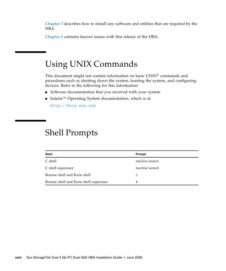
Using UNIX CommandsThis document might not contain information on basic UNIX® commands andprocedures such as shutting down the system, booting the system, and configuringdevices. Refer to the following for this information:
■ Software documentation that you received with your system
■ Solaris™ Operating System documentation, which is at
http://docs.sun.com
Shell Prompts
Shell Prompt
C shell machine-name%
C shell superuser machine-name#
Bourne shell and Korn shell $
Bourne shell and Korn shell superuser #
xxiv Sun StorageTek Dual 4 Gb FC Dual GbE HBA Installation Guide • June 2008
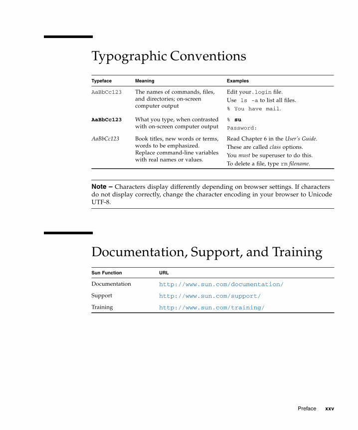
Typographic Conventions
Note – Characters display differently depending on browser settings. If charactersdo not display correctly, change the character encoding in your browser to UnicodeUTF-8.
Documentation, Support, and Training
Typeface Meaning Examples
AaBbCc123 The names of commands, files,and directories; on-screencomputer output
Edit your.login file.Use ls -a to list all files.% You have mail.
AaBbCc123 What you type, when contrastedwith on-screen computer output
% su
Password:
AaBbCc123 Book titles, new words or terms,words to be emphasized.Replace command-line variableswith real names or values.
Read Chapter 6 in the User’s Guide.These are called class options.You must be superuser to do this.To delete a file, type rm filename.
Sun Function URL
Documentation http://www.sun.com/documentation/
Support http://www.sun.com/support/
Training http://www.sun.com/training/
Preface xxv

Third-Party Web SitesSun is not responsible for the availability of third-party web sites mentioned in thisdocument. Sun does not endorse and is not responsible or liable for any content,advertising, products, or other materials that are available on or through such sitesor resources. Sun will not be responsible or liable for any actual or alleged damageor loss caused by or in connection with the use of or reliance on any such content,goods, or services that are available on or through such sites or resources.
Sun Welcomes Your CommentsSun is interested in improving its documentation and welcomes your comments andsuggestions. You can submit your comments by going to:
http://www.sun.com/hwdocs/feedback
Please include the title and part number of your document with your feedback:
Sun StorageTek Dual 4 Gb FC Dual GbE HBA Installation Guide, part number 820-3783-11
xxvi Sun StorageTek Dual 4 Gb FC Dual GbE HBA Installation Guide • June 2008
CHAPTER 1
HBA Overview
This chapter provides a basic overview of the Sun StorageTek Dual 4 Gb FC DualGbE host bus adapter (HBA), which uses QLogic technology. This chapter alsodescribes the various operating systems, host platforms, storage, and infrastructureconfigurations that support the HBA and lists the HBA environmental requirements.This chapter contains the following topics:
■ “Kit Contents” on page 1
■ “HBA Features and Specifications” on page 1
■ “Operating System and Technology Requirements” on page 3
■ “System Interoperability” on page 4
■ “Environmental Requirements” on page 7
Kit Contents■ Sun StorageTek Dual 4 Gb FC Dual GbE HBA
■ Accessing Documentation document (part number: 820-2299-xx)
HBA Features and SpecificationsThe Sun StorageTek Dual 4 Gb FC Dual GbE HBA (SG-XPCIE2FCGBE-Q-Z) consistsof a single-wide, ExpressModule™ bus expansion board. The board interfaces aneight-lane PCI-Express bus, with four lanes supporting two Fibre Channel (FC)optical media ports and four lanes supporting two UTP (copper) Gigabit Ethernetports. The two FC ports operate at 4 Gbit/sec and feature 4/2/1 autonegotiation.
1
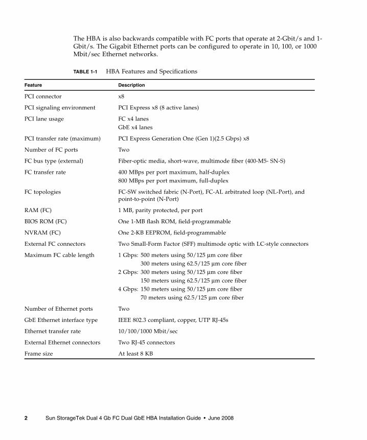
The HBA is also backwards compatible with FC ports that operate at 2-Gbit/s and 1-Gbit/s. The Gigabit Ethernet ports can be configured to operate in 10, 100, or 1000Mbit/sec Ethernet networks.
TABLE 1-1 HBA Features and Specifications
Feature Description
PCI connector x8
PCI signaling environment PCI Express x8 (8 active lanes)
PCI lane usage FC x4 lanesGbE x4 lanes
PCI transfer rate (maximum) PCI Express Generation One (Gen 1)(2.5 Gbps) x8
Number of FC ports Two
FC bus type (external) Fiber-optic media, short-wave, multimode fiber (400-M5- SN-S)
FC transfer rate 400 MBps per port maximum, half-duplex800 MBps per port maximum, full-duplex
FC topologies FC-SW switched fabric (N-Port), FC-AL arbitrated loop (NL-Port), andpoint-to-point (N-Port)
RAM (FC) 1 MB, parity protected, per port
BIOS ROM (FC) One 1-MB flash ROM, field-programmable
NVRAM (FC) One 2-KB EEPROM, field-programmable
External FC connectors Two Small-Form Factor (SFF) multimode optic with LC-style connectors
Maximum FC cable length 1 Gbps: 500 meters using 50/125 µm core fiber300 meters using 62.5/125 µm core fiber
2 Gbps: 300 meters using 50/125 µm core fiber150 meters using 62.5/125 µm core fiber
4 Gbps: 150 meters using 50/125 µm core fiber70 meters using 62.5/125 µm core fiber
Number of Ethernet ports Two
GbE Ethernet interface type IEEE 802.3 compliant, copper, UTP RJ-45s
Ethernet transfer rate 10/100/1000 Mbit/sec
External Ethernet connectors Two RJ-45 connectors
Frame size At least 8 KB
2 Sun StorageTek Dual 4 Gb FC Dual GbE HBA Installation Guide • June 2008
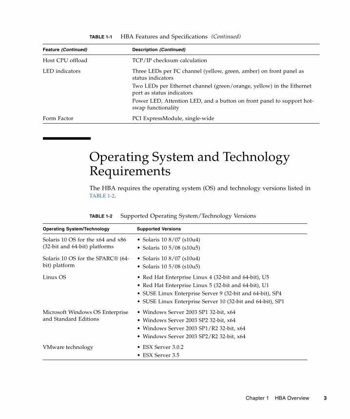
Operating System and TechnologyRequirementsThe HBA requires the operating system (OS) and technology versions listed inTABLE 1-2.
Host CPU offload TCP/IP checksum calculation
LED indicators Three LEDs per FC channel (yellow, green, amber) on front panel asstatus indicatorsTwo LEDs per Ethernet channel (green/orange, yellow) in the Ethernetport as status indicatorsPower LED, Attention LED, and a button on front panel to support hot-swap functionality
Form Factor PCI ExpressModule, single-wide
TABLE 1-2 Supported Operating System/Technology Versions
Operating System/Technology Supported Versions
Solaris 10 OS for the x64 and x86(32-bit and 64-bit) platforms
• Solaris 10 8/07 (s10u4)• Solaris 10 5/08 (s10u5)
Solaris 10 OS for the SPARC® (64-bit) platform
• Solaris 10 8/07 (s10u4)• Solaris 10 5/08 (s10u5)
Linux OS • Red Hat Enterprise Linux 4 (32-bit and 64-bit), U5• Red Hat Enterprise Linux 5 (32-bit and 64-bit), U1• SUSE Linux Enterprise Server 9 (32-bit and 64-bit), SP4• SUSE Linux Enterprise Server 10 (32-bit and 64-bit), SP1
Microsoft Windows OS Enterpriseand Standard Editions
• Windows Server 2003 SP1 32-bit, x64• Windows Server 2003 SP2 32-bit, x64• Windows Server 2003 SP1/R2 32-bit, x64• Windows Server 2003 SP2/R2 32-bit, x64
VMware technology • ESX Server 3.0.2• ESX Server 3.5
TABLE 1-1 HBA Features and Specifications (Continued)
Feature (Continued) Description (Continued)
Chapter 1 HBA Overview 3

System InteroperabilityThis section provides information about selected platforms, storage systems,switches, and software that are compatible with the heterogeneous FC and Ethernetnetwork design of the HBA. This section contains the following topics:
■ “Host Platform Support” on page 4
■ “Storage Support” on page 5
■ “Switch Support” on page 6
■ “Software Support” on page 7
Host Platform SupportThe HBA is supported by the platforms and operating systems listed in TABLE 1-3.
TABLE 1-3 Platform and Operating System Support
Platform Supported OS/Technology
SPARC Servers
Sun Blade™ T6300 Solaris
Sun Blade T6320 Solaris
Sun x64 Servers
Sun Blade X6220 Solaris, Linux, Windows, VMware
Sun Blade X6450 Solaris, Linux, Windows, VMware
Sun Blade X6250 Solaris, Linux, Windows, VMware
Sun Blade X8400 Solaris, Linux, Windows, VMware
Sun Blade X8420 Solaris, Linux, Windows, VMware
Sun Blade X8440 Solaris, Linux, Windows, VMware
4 Sun StorageTek Dual 4 Gb FC Dual GbE HBA Installation Guide • June 2008

Storage SupportThis section lists the arrays, storage systems, chassis, and tape storage devicessupported by the HBA. This section provides the following topics:
■ “Array Support” on page 5
■ “Tape Storage Support” on page 5
Array SupportThe HBA supports the following arrays:
■ Sun StorageTek 2540
■ Sun StorageTek 3510
■ Sun StorageTek 3511
■ Sun StorageTek 6120
■ Sun StorageTek 6130
■ Sun StorageTek 6140
■ Sun StorageTek 6540
Tape Storage SupportThe HBA supports the following tape storage devices:
■ Sun StorageTek SL24 tape autoloader
■ Sun StorageTek SL48 tape library
■ Sun StorageTek SL500 modular library
■ Sun StorageTek SDLT600 and DLT-S4 tape drives
■ Sun StorageTek L1400 tape library
■ Sun StorageTek LTO-2, LTO-3, and LTO-4 tape drives
■ Sun StorageTek SL8500 modular library
■ Sun StorageTek Virtual Tape Library (VTL): VTL Value and VTL Plus
■ Sun StorageTek T10000A and T10000B tape drives
■ Sun StorageTek T9840A, T9840B, T9840C, and T9840D tape drives
■ Sun StorageTek T9940B tape drive
Chapter 1 HBA Overview 5
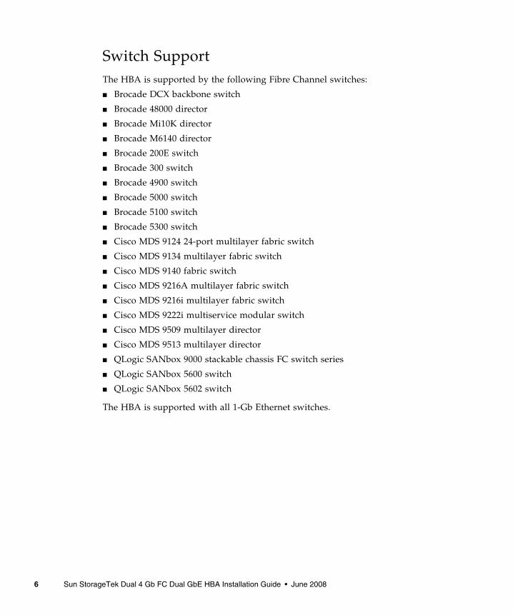
Switch SupportThe HBA is supported by the following Fibre Channel switches:
■ Brocade DCX backbone switch
■ Brocade 48000 director
■ Brocade Mi10K director
■ Brocade M6140 director
■ Brocade 200E switch
■ Brocade 300 switch
■ Brocade 4900 switch
■ Brocade 5000 switch
■ Brocade 5100 switch
■ Brocade 5300 switch
■ Cisco MDS 9124 24-port multilayer fabric switch
■ Cisco MDS 9134 multilayer fabric switch
■ Cisco MDS 9140 fabric switch
■ Cisco MDS 9216A multilayer fabric switch
■ Cisco MDS 9216i multilayer fabric switch
■ Cisco MDS 9222i multiservice modular switch
■ Cisco MDS 9509 multilayer director
■ Cisco MDS 9513 multilayer director
■ QLogic SANbox 9000 stackable chassis FC switch series
■ QLogic SANbox 5600 switch
■ QLogic SANbox 5602 switch
The HBA is supported with all 1-Gb Ethernet switches.
6 Sun StorageTek Dual 4 Gb FC Dual GbE HBA Installation Guide • June 2008

Software SupportThe HBA supports the software applications listed in TABLE 1-4.
Environmental RequirementsThe HBA environmental requirements are listed in TABLE 1-5.
TABLE 1-4 Supported Software Applications
Software (minimum version) Supported OS
Sun Cluster 3.x Solaris
VERITAS Software Foundation 5.0 Solaris
Sun StorEdge™ Enterprise Backup Software 7.2 Solaris, Linux, and Windows
VERITAS NetBackup 5.1 Solaris
Sun StorageTek Availability Suite 3.0 Solaris
Sun StorageTek Utilization Suite 3.0 Solaris
Sun StorageTek Performance Suite 3.0 Solaris
TABLE 1-5 HBA Environmental Requirements
Specification Operating Non-Operating
Temperature 0˚ to 40˚C, noncondensing -40˚C to 70˚C, noncondensing
Humidity 10% to 90% RH, noncondensing, 27˚Cmax wet bulb
93% RH, noncondensing, 38˚C max wet bulb
Altitude 3000m 12,000m
Vibration 0.20G in all axes, 5-500 Hz sine 1.0G in all axes, 5-500 Hz sine
Shock Operating: 5G, 11 ms half-sine 30G 11 ms half-sine
Chapter 1 HBA Overview 7

8 Sun StorageTek Dual 4 Gb FC Dual GbE HBA Installation Guide • June 2008
CHAPTER 2
Hardware Installation and Removal
This chapter describes how to install and remove the HBA. Refer to your systeminstallation or service manual for detailed instructions.
This chapter contains the following topics:
■ “Observing ESD and Handling Precautions” on page 9
■ “Installing the Hardware” on page 10
■ “LED Descriptions and Status” on page 13
■ “Configuring the HBA For Hot-Plug Operation” on page 16
■ “Testing the Installation” on page 17
■ “Removing the Hardware” on page 18
Observing ESD and HandlingPrecautions
Caution – Damage to the HBA can occur as the result of careless handling orelectrostatic discharge (ESD). Always handle the HBA with care to avoid damage toelectrostatic sensitive components.
To minimize the possibility of ESD-related damage, use both a workstation antistaticmat and an ESD wrist strap. You can get an ESD wrist strap from any reputableelectronics store or from Sun as part number #250-1007. Observe the followingprecautions to avoid ESD-related problems:■ Leave the HBA in its antistatic bag until you are ready to install it in the system.
9

■ Always use a properly fitted and grounded wrist strap or other suitable ESDprotection when handling the HBA and observe proper ESD groundingtechniques.
■ Hold the HBA by the edge of the PCB, not the connectors.
■ Place the HBA on a properly grounded antistatic work surface pad when it is out of itsprotective antistatic bag.
Installing the HardwareFollow the procedures in this section to install the hardware:
■ “To Install the HBA” on page 10
■ “To Connect the HBA” on page 11
■ “To Power On the HBA” on page 12
▼ To Install the HBA1. Attach an ESD wrist strap (see “Observing ESD and Handling Precautions” on
page 9).
2. Refer to your system installation or service manual to determine an appropriateExpressModule slot in which to install the HBA.
3. Press down the plastic tab to release the ExpressModule latch and pull thelever out until it is nearly perpendicular with the ExpressModule front panel.
10 Sun StorageTek Dual 4 Gb FC Dual GbE HBA Installation Guide • June 2008

FIGURE 2-1 Releasing the HBA Latch
4. Insert the HBA into its slot, being careful that the tooth on the bottom of thelever does not come in contact with the chassis sheet metal during insertion.
5. When the HBA is inserted nearly all the way into its slot, push the lever backinto its fully closed position, allowing the lever tooth to insert the HBA fullyinto place.
▼ To Connect the HBA
Note – The HBA does not allow normal data transmission on an optical link unlessit is connected to another similar or compatible Fibre Channel (FC) product (that is,multimode to multimode).
1. Use multimode fiber-optic cable, intended for short-wave lasers, that adheres tothe specifications in TABLE 2-1.
TABLE 2-1 Optical Cable Specifications
Fiber-Optic Cable Maximum Length Minimum Length Connector
62.5/125 µm(multimode)
300 meters at 1.0625 Gbps150 meters at 2.125 Gbps70 meters at 4.25 Gbps
2 meters LC
50/125 µm(multimode)
500 meters at 1.0625 Gbps300 meters at 2.125 Gbps150 meters at 4.25 Gbps
2 meters LC
Chapter 2 Hardware Installation and Removal 11
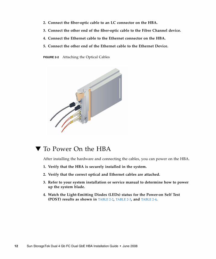
2. Connect the fiber-optic cable to an LC connector on the HBA.
3. Connect the other end of the fiber-optic cable to the Fibre Channel device.
4. Connect the Ethernet cable to the Ethernet connector on the HBA.
5. Connect the other end of the Ethernet cable to the Ethernet Device.
FIGURE 2-2 Attaching the Optical Cables
▼ To Power On the HBAAfter installing the hardware and connecting the cables, you can power on the HBA.
1. Verify that the HBA is securely installed in the system.
2. Verify that the correct optical and Ethernet cables are attached.
3. Refer to your system installation or service manual to determine how to powerup the system blade.
4. Watch the Light-Emitting Diodes (LEDs) status for the Power-on Self Test(POST) results as shown in TABLE 2-2, TABLE 2-3, and TABLE 2-4.
12 Sun StorageTek Dual 4 Gb FC Dual GbE HBA Installation Guide • June 2008

LED Descriptions and StatusThis section contains the following topics:
■ “LED and Switch Locations” on page 13
■ “Fibre Channel LED Indicator Status” on page 15
■ “Ethernet LED Indicator Status” on page 15
■ “Power and Attention Switch LED Scheme” on page 16
LED and Switch LocationsSee FIGURE 2-3 to determine the LED locations.
Each port has a corresponding set of LEDs that provide a visual indication of theoperating state.
Chapter 2 Hardware Installation and Removal 13
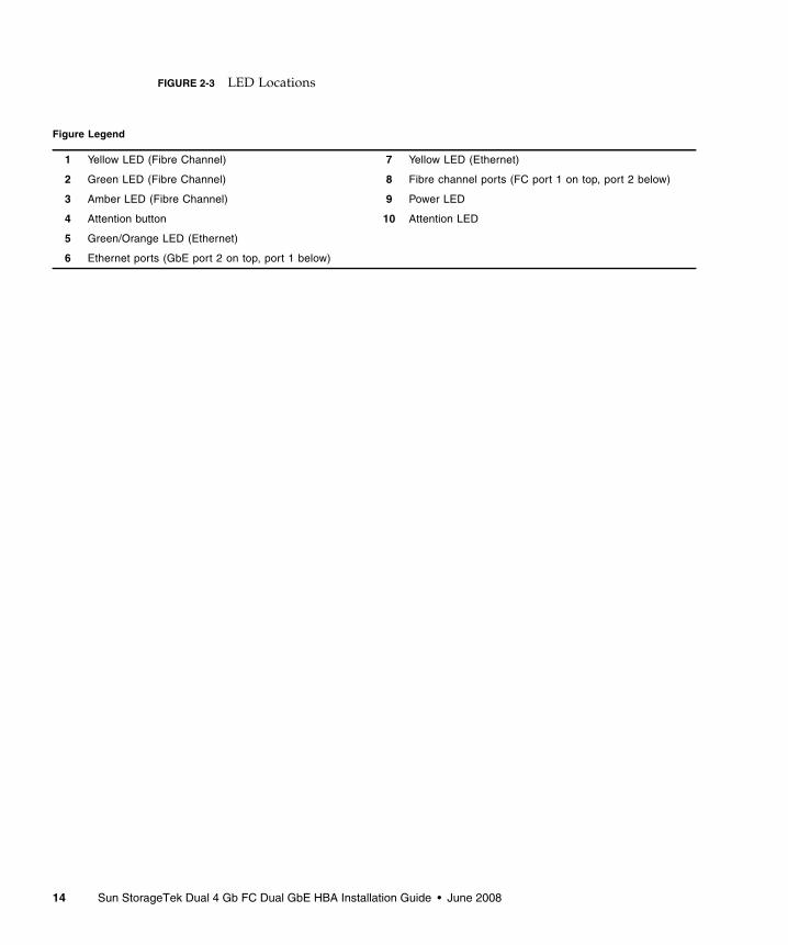
FIGURE 2-3 LED Locations
Figure Legend
1 Yellow LED (Fibre Channel) 7 Yellow LED (Ethernet)
2 Green LED (Fibre Channel) 8 Fibre channel ports (FC port 1 on top, port 2 below)
3 Amber LED (Fibre Channel) 9 Power LED
4 Attention button 10 Attention LED
5 Green/Orange LED (Ethernet)
6 Ethernet ports (GbE port 2 on top, port 1 below)
14 Sun StorageTek Dual 4 Gb FC Dual GbE HBA Installation Guide • June 2008

Fibre Channel LED Indicator StatusTABLE 2-2 summarizes the Fibre Channel LED indicator combinations (LEDs 1, 2, and3 in FIGURE 2-3 ).
Ethernet LED Indicator StatusTABLE 2-3 summarizes the Ethernet LED indicator combinations (LEDs 5 and 7 inFIGURE 2-3).
TABLE 2-2 Fibre Channel LED Indicator Status Definitions
Yellow LED (4 Gbps) Green LED (2 Gbps) Amber LED (1 Gbps) Activity
Off Off Off Power off
On On On Power on
Blinking Blinking Blinking Power on (firmware initialization)
Yellow, Green, and Amber LEDs blinking alternately Firmware error
Off Off On/blinking Online, 1 Gbps link I/O activity
Off On/blinking Off Online, 2 Gbps link I/O activity
On/blinking Off Off Online, 4 Gbps link I/O activity
Blinking Off Blinking Beacon
TABLE 2-3 Ethernet LED Indicator Status Definitions
Top LED (Link/Speed)Bottom LED(Link/Activity)
Hardware State SpeedGreen LED Orange LED Yellow LED
Off Off Off Power on, link is down All
Off Off On Power on, link is up 10 Mbit
Off On On 100 Mbit
On Off On GbE
Off Off Blinking Network activity 10 Mbit
Off On Blinking 100 Mbit
On Off Blinking GbE
Chapter 2 Hardware Installation and Removal 15
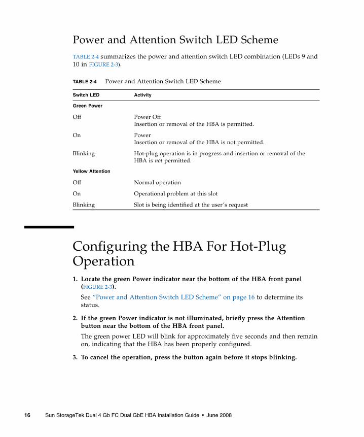
Power and Attention Switch LED SchemeTABLE 2-4 summarizes the power and attention switch LED combination (LEDs 9 and10 in FIGURE 2-3).
Configuring the HBA For Hot-PlugOperation1. Locate the green Power indicator near the bottom of the HBA front panel
(FIGURE 2-3).
See “Power and Attention Switch LED Scheme” on page 16 to determine itsstatus.
2. If the green Power indicator is not illuminated, briefly press the Attentionbutton near the bottom of the HBA front panel.
The green power LED will blink for approximately five seconds and then remainon, indicating that the HBA has been properly configured.
3. To cancel the operation, press the button again before it stops blinking.
TABLE 2-4 Power and Attention Switch LED Scheme
Switch LED Activity
Green Power
Off Power OffInsertion or removal of the HBA is permitted.
On PowerInsertion or removal of the HBA is not permitted.
Blinking Hot-plug operation is in progress and insertion or removal of theHBA is not permitted.
Yellow Attention
Off Normal operation
On Operational problem at this slot
Blinking Slot is being identified at the user’s request
16 Sun StorageTek Dual 4 Gb FC Dual GbE HBA Installation Guide • June 2008
Testing the InstallationThis section contains the following topics:
■ “To Test the Installation for the Solaris OS” on page 17
■ “To Test the Installation for the Windows OS” on page 17
■ “To Test the Installation for the VMware Technology” on page 18
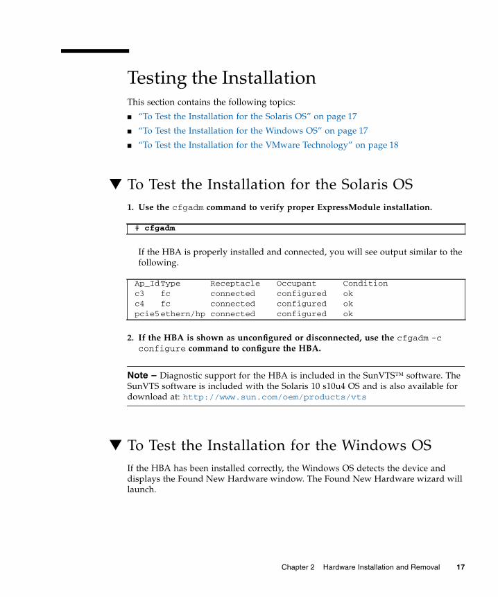
▼ To Test the Installation for the Solaris OS1. Use the cfgadm command to verify proper ExpressModule installation.
If the HBA is properly installed and connected, you will see output similar to thefollowing.
2. If the HBA is shown as unconfigured or disconnected, use the cfgadm -cconfigure command to configure the HBA.
Note – Diagnostic support for the HBA is included in the SunVTS™ software. TheSunVTS software is included with the Solaris 10 s10u4 OS and is also available fordownload at: http://www.sun.com/oem/products/vts
▼ To Test the Installation for the Windows OSIf the HBA has been installed correctly, the Windows OS detects the device anddisplays the Found New Hardware window. The Found New Hardware wizard willlaunch.
# cfgadm
Ap_IdType Receptacle Occupant Conditionc3 fc connected configured okc4 fc connected configured okpcie5ethern/hp connected configured ok
Chapter 2 Hardware Installation and Removal 17

Note – Leave the Found New Hardware wizard window open, and then load theFibre Channel and Ethernet drivers, as described in “Installing Software for theWindows OS” on page 29.
▼ To Test the Installation for the VMwareTechnologyIf the HBA has been installed correctly, you will see the following line in the/var/log/vmkernel file:
Removing the HardwareThe following instructions describe the tasks required to remove the HBA. Refer toyour system installation or service manual for detailed HBA removal instructions.
The following steps summarize the hardware removal process:
1. Either halt the operating system and remove power from the server blade, orprepare the HBA for hot-plug removal with one of the following:
■ The HBA Attention button
■ The Solaris OS
2. Remove the HBA hardware.
▼ To Prepare the HBA for Removal Using the HBAAttention Button1. Press and release the Attention button near the bottom of the HBA front panel
(FIGURE 2-3).
The Attention LED near the button will blink for approximately five seconds,indicating that the HBA is being prepared for removal.
2. If you want to stop the operation, press the button again before the LED stopsblinking.
VMKernel qla2300_707.o loaded successfully
18 Sun StorageTek Dual 4 Gb FC Dual GbE HBA Installation Guide • June 2008

3. When the LED stops blinking and goes dark, you can remove the HBA.
▼ To Prepare the HBA for Hot-Plug Removal(Using the Solaris OS)If you want to remove the HBA without first halting the operating system andremoving power from the associated server blade, you can prepare it for removal asfollows:
1. Use the cfgadm command to identify the HBA to be removed.
2. Use the ifconfig command to identify the Ethernet ports on the HBA to bedisconnected.
3. Use the unplumb command to disconnect the Ethernet ports on the HBA.
4. Use the cfgadm -c unconfigure command to unconfigure the attachmentpoint ID (Ap_Id) for the HBA.
5. Use the cfgadm -c disconnect command to prepare the HBA for removal.
A blinking Power indicator LED indicates that the HBA is being prepared forremoval. A dark Power indicator LED indicates that the HBA is ready to beremoved.
▼ To Remove the HBA● Use an ESD strap, depress the ExpressModule latch to disengage the HBA, and
then pull forward and down to dislodge it. You can now remove the HBA.
Ap_IdType Receptacle Occupant Conditionpcie5ether/hp connected configured okpcie6ether/hp connected configured ok
e1000g5: flags=201000803<UP,BROADCAST,MULTICAST,IPv4,CoS> mtu 1500 index 6 inet 200.17.188.224 netmask ffffff00 broadcast 200.17.188.255 ether 0:c0:dd:9:a9:7b
Chapter 2 Hardware Installation and Removal 19

20 Sun StorageTek Dual 4 Gb FC Dual GbE HBA Installation Guide • June 2008

CHAPTER 3
Software Installation
After you have completed the hardware installation and powered on the computer,follow the instructions in this chapter for your operating system to install the HBAdriver and any other utilities required for the installation.
This chapter contains the following topics:
■ “Installing Software for the Solaris OS” on page 21
■ “Installing Software for the Red Hat/SUSE Linux OS” on page 23
■ “Installing Software for the VMware Technology” on page 28
■ “Installing Software for the Windows OS” on page 29
■ “Installing a CLI for Updating the BIOS and FCode” on page 32
Installing Software for the Solaris OSThis section contains the following topics:
■ “Installing the Fibre Channel Driver” on page 21
■ “Installing the Ethernet Driver” on page 22
■ “Diagnostic Support for the Solaris OS” on page 22
Installing the Fibre Channel DriverThe qlc HBA driver for the Solaris OS is included with the Solaris 10 8/07 (s10u4)OS release; no further action is required. The latest version of the qlc driver isincluded with the following Solaris patches:
■ 125165 (for the x64/x86 platform)
■ 125166 (for the SPARC platform)
21

You can download these patches from the SunSolve website at:
http://sunsolve.sun.com/pub-cgi/show.pl?target=patchpage
▼ To Install or Update the qlc HBA Driver From a Patch1. Log in as the root user.
2. Navigate to the directory that contains the patch.
3. Add the latest patch by using the patchadd command.
Installing the Ethernet DriverCheck the SunSolve web site to ensure that you have the latest patch clusters andsecurity patches for the ethernet driver. You can download the latest patch clustersand security patches at:
http://sunsolve.sun.com/pub-cgi/show.pl?target=patchpage
Diagnostic Support for the Solaris OSDiagnostic support for the HBA is included in the SunVTS software beginning withversion 6.3. The SunVTS software is included with the Solaris 10 8/07 (s10u4) OS.The SunVTS software is also available for download at:http://www.sun.com/oem/products/vts
The qlctest utility, which is provided as part of the SunVTS software, supports thefollowing functions:
■ Connectivity verification
■ Firmware version and checksum testing
■ Self-testing
■ Loopback tests
■ External
■ Internal, single-bit
■ Internal, 10-bit
■ Mailbox
# patchadd patch-number
22 Sun StorageTek Dual 4 Gb FC Dual GbE HBA Installation Guide • June 2008

Installing Software for the RedHat/SUSE Linux OSThis section describes how to download and install the fibre channel and ethernetdrivers required by the HBA. It also describes how to install diagnostic supportsoftware for the HBA. This section contains the following topics:
■ “Downloading the Red Hat/SUSE Linux Drivers” on page 23
■ “Installing the Red Hat/SUSE Linux Drivers” on page 24
■ “Diagnostic Support for the Red Hat/SUSE OS” on page 28
Downloading the Red Hat/SUSE Linux DriversThis section describes how to download the fibre channel and ethernet driver for theHBA. This section contains the following topics:
■ “To Download the Fibre Channel Driver” on page 23
■ “To Download the Ethernet Driver” on page 24
▼ To Download the Fibre Channel Driver1. Go to the QLogic support site for Sun Microsystems at:
http://support.qlogic.com/support/defaultsun_page.asp
2. Locate the table containing the SG-XPCIE2FCGBE-Q-Z model.
3. At the bottom of the table, in the Software for row, click Linux.
4. In the Red Hat or SUSE Linux table, find the appropriate driver (the file nameis in the format qla2x00-vx.yy.zz-dist.tgz).
5. In the Download column of that row, click Download.
6. Save the file to a directory on the hard disk of the computer.
Note – Because the driver distribution file is now larger than 1.44 Mb, it cannot fiton a 1.44 Mb floppy disk; therefore, you must use a USB driver or local hard disk todownload the file.
Chapter 3 Software Installation 23

▼ To Download the Ethernet Driver1. Go to the QLogic support site for Sun Microsystems at:
http://support.qlogic.com/support/defaultsun_page.asp
2. Locate and click the link for the Ethernet drivers.
3. Find and select the Go to Download Center link.
4. Type 82571EB in the search window and select search.
5. Locate and select Intel 82571EB Gigabit Ethernet Controller.
6. Using the drop-down menu, either select the individual OS or All OperatingSystems, then click Go!.
Individual software downloads are now available.
7. Download and save the driver on the hard disk of the computer.
Installing the Red Hat/SUSE Linux DriversAfter you download the drivers, as described in “Downloading the Red Hat/SUSELinux Drivers” on page 23, you can install the drivers by following the steps in thissection:
1. “To Build the Fibre Channel Driver” on page 24
2. “To Load the Newly Built Fibre Channel Driver” on page 25
3. “To Build and Load the Ethernet HBA Driver” on page 27
▼ To Build the Fibre Channel DriverThe driver installation makes extensive use of the build.sh script, which is locatedin driver source (extras/build.sh).
From the source code, you can build a qla2xxx.ko module and aqla2xxx_conf.ko module for the host. You can then choose to load the drivermanually or automatically, as described in “To Load the Newly Built Fibre ChannelDriver” on page 25.
24 Sun StorageTek Dual 4 Gb FC Dual GbE HBA Installation Guide • June 2008
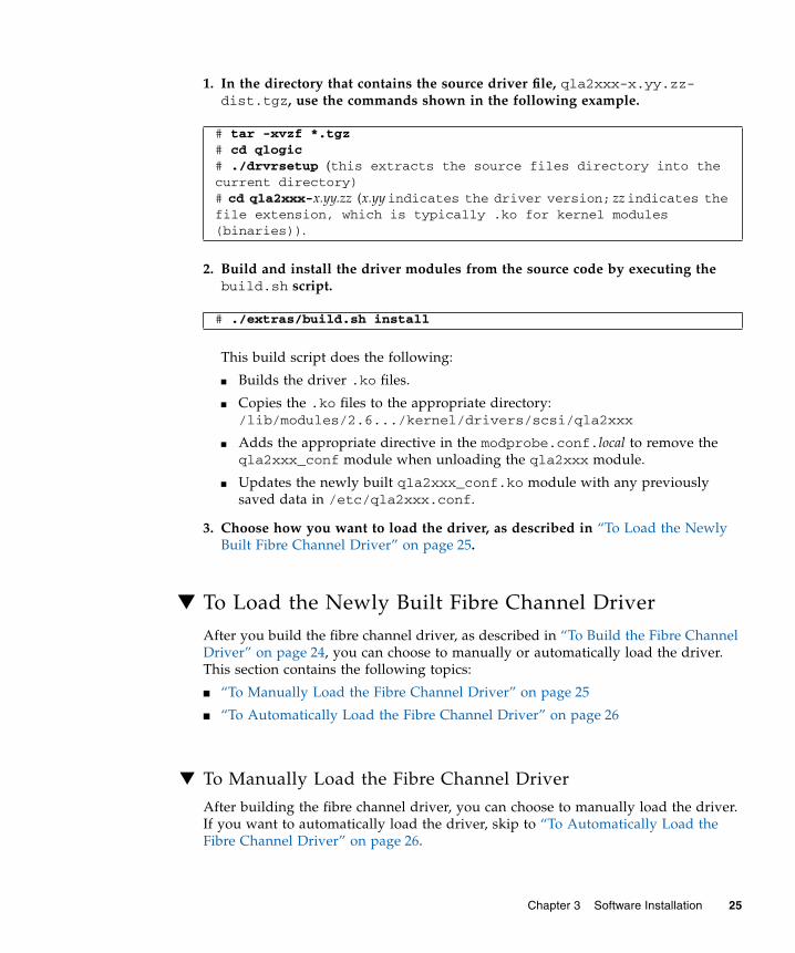
1. In the directory that contains the source driver file, qla2xxx-x.yy.zz-dist.tgz, use the commands shown in the following example.
2. Build and install the driver modules from the source code by executing thebuild.sh script.
This build script does the following:
■ Builds the driver .ko files.
■ Copies the .ko files to the appropriate directory:/lib/modules/2.6.../kernel/drivers/scsi/qla2xxx
■ Adds the appropriate directive in the modprobe.conf.local to remove theqla2xxx_conf module when unloading the qla2xxx module.
■ Updates the newly built qla2xxx_conf.ko module with any previouslysaved data in /etc/qla2xxx.conf.
3. Choose how you want to load the driver, as described in “To Load the NewlyBuilt Fibre Channel Driver” on page 25.
▼ To Load the Newly Built Fibre Channel DriverAfter you build the fibre channel driver, as described in “To Build the Fibre ChannelDriver” on page 24, you can choose to manually or automatically load the driver.This section contains the following topics:
■ “To Manually Load the Fibre Channel Driver” on page 25
■ “To Automatically Load the Fibre Channel Driver” on page 26
▼ To Manually Load the Fibre Channel Driver
After building the fibre channel driver, you can choose to manually load the driver.If you want to automatically load the driver, skip to “To Automatically Load theFibre Channel Driver” on page 26.
# tar -xvzf *.tgz# cd qlogic# ./drvrsetup (this extracts the source files directory into thecurrent directory)# cd qla2xxx-x.yy.zz (x.yyindicates the driver version; zzindicates thefile extension, which is typically .ko for kernel modules(binaries)).
# ./extras/build.sh install
Chapter 3 Software Installation 25

1. Build the driver binary, as described in “To Build the Fibre Channel Driver” onpage 24.
2. Manually load the driver by using the modprobe -v command.
3. Now that the fibre channel driver is manually loaded, you can build and loadthe ethernet driver, as described in “To Build and Load the Ethernet HBADriver” on page 27.
4. If you want to manually unload the driver, use the modprobe -r command.
▼ To Automatically Load the Fibre Channel Driver
After building the fibre channel driver, you can choose to automatically load thedriver. If you want to manually load the fibre channel driver, see “To Manually Loadthe Fibre Channel Driver” on page 25.
1. Build the driver binary, as described in “To Build the Fibre Channel Driver” onpage 24.
2. Install the driver module (*.ko) files to the appropriate kernel moduledirectory.
3. For Red Hat Linux users, edit the /etc/modprobe.conf file and add thefollowing entries, if they are not present:
■ alias scsi_hostadapter1 qla2xxx_conf (for use only with SANsurfer)
■ alias scsi_hostadapter2 qla2xxx
4. For SUSE Linux users, edit the /etc/sysconfig/kernel file and modify theINITRD_MODULES directive as shown in the following example.
In this example, note that you must add the first module, qla2xxx_conf (forSANsurfer), followed by the qla2xxx module. The qla2xxx_conf module is foruse only with SANsurfer while the qla2xxx module is a common module.
# modprobe -v qla2xxx
# modprobe -r qla2xxx# modprobe -r qla2xxx_conf (SANsurfer use only)
# ./extras/build.sh install
...INITRD_MODULES=".... qla2xxx_conf qla2xxx"...
26 Sun StorageTek Dual 4 Gb FC Dual GbE HBA Installation Guide • June 2008

5. Change to the /boot directory.
6. Back up the current RAMDISK image.
7. Build the RAMDISK image with the mkinitrd -f command.
8. Reboot the system to load the RAMDISK image with the driver.
9. You can now build and load the ethernet driver, as described in “To Build andLoad the Ethernet HBA Driver” on page 27.
▼ To Build and Load the Ethernet HBA Driver1. Build the Ethernet HBA driver.
2. Change to the rpm directory.
3. Install the Ethernet rpms, using the same command for both Red Hat and SUSEOSes.
4. Use the depmod command to register the HBA.
5. Manually load the e1000 driver for all instances.
# cp -f initrd-2.6.kernel-version.img initrd-2.6.kernel-version.img.bak
Red Hat: # mkinitrd -f initrd-2.6.kernel-version.img kernel-versionSUSE: # /sbin/mk_initrd
Red Hat: # rpmbuild --rebuild sun-pci-e-dual-gigabit-kernel-6.1.5.src.rpm
Red Hat: # cd /usr/src/redhat/RPMS/arch
# rpm -ivh sun-pci-e-dual-gigabit-kernel-6.1.5.rpm
# depmod
# modprobe e1000
Chapter 3 Software Installation 27
Diagnostic Support for the Red Hat/SUSE OSDiagnostic support for the HBA is available through the SANsurfer PRO graphicaluser interface (GUI) utility or the SANsurfer command-line interface (CLI) utility.These utilities support the following functions:
■ Connectivity verification
■ BIOS, FCode, EFI, and firmware version information
■ Link status, including topology, data rate, and statistics
■ Vital product data (VPD) information
■ Attached devices list
■ Option ROM, NVRAM update utilities
■ Loopback test
■ Read/Write Buffer test
▼ To Install Diagnostic Support for the Red Hat/SUSELinux OS1. Go to the QLogic support site for Sun Microsystems at:
http://support.qlogic.com/support/defaultsun_page.asp
2. Locate the table containing the SG-XPCIE2FCGBE-Q-Z model.
3. At the bottom of the table, click Windows.
4. Locate the SANsurfer CLI (command-line interface) or SANsurfer PRO (GUI)diagnostic utility.
5. Click Download to copy diagnostic archive to a local file system.
6. Click Readme link for additional information.
Installing Software for the VMwareTechnologyThe HBA drivers included on the VMware distribution are sufficient for supportingthe HBA. No further action is required.
28 Sun StorageTek Dual 4 Gb FC Dual GbE HBA Installation Guide • June 2008

To verify that the drivers loaded successfully, look for the following lines in the/var/log/vmkernel file:
The first line indicates that the fibre channel driver loaded successfully. The secondline indicates that the ethernet driver loaded successfully.
Installing Software for the Windows OSThis section describes how to download and install the fibre channel and ethernetdrivers required by the HBA. It also describes how to install diagnostic supportsoftware for the HBA. This section contains the following topics:
■ “To Download the Fibre Channel Driver” on page 29
■ “To Install the Fibre Channel Driver” on page 30
■ “To Download and Install the Ethernet Driver” on page 30
■ “Diagnostic Support for the Windows OS” on page 31
▼ To Download the Fibre Channel Driver1. Go to the QLogic support site for Sun Microsystems at:
http://support.qlogic.com/support/defaultsun_page.asp
2. Locate the table containing the SG-XPCIE2FCGBE-Q-Z model.
3. At the bottom of the table, in the Software for row, click Windows.
4. In the table for your Windows operating system, find the appropriate driver.
5. In the Download column of that row, click Download.
6. Save the file to a directory on the hard disk of the computer.
7. Unzip (extract) the driver files to a location on the hard disk of the computer.
VMKernel qla2300_707.o loaded successfullye1000.o loaded successfully
Chapter 3 Software Installation 29
▼ To Install the Fibre Channel DriverAfter installing the HBA and restarting the computer, the Windows OS detects thenewly installed device and displays the Found New Hardware with Fibre ChannelController message. The Found New Hardware wizard launches.
Note – This procedure requires a system configured with the latest Service Pack andWindows Update.
1. On the first screen of the Found New Hardware wizard, click Search for asuitable driver for my device (recommended), and then click Next.
2. Browse to the location on the where you downloaded the Fibre Channel driver,then click Next.
Windows displays a message, letting you know it found a driver for this device.
3. On the Completing the Found New Hardware Wizard window, click Finish.
4. If the system displays the following message, click Yes to restart the computer:
▼ To Download and Install the Ethernet Driver1. Go to the QLogic support site for Sun Microsystems at:
http://support.qlogic.com/support/defaultsun_page.asp
2. Locate and click the link for the Ethernet drivers.
3. Find and select the Go to Download Center link.
4. Type 82571EB in the search window and select search.
5. Locate and select Intel 82571EB Gigabit Ethernet Controller.
6. Using the drop-down menu, select either the individual OS or All OperatingSystems, then click Go!.
Individual software downloads will now be available.
7. Download and save the driver on the hard disk of the computer.
System Settings Change. Windows has finished installing a newdevice. The software that supports your device requires that yourestart your computer. You must restart your computer before thenew settings will take effect. Do you want to restart your computernow?
30 Sun StorageTek Dual 4 Gb FC Dual GbE HBA Installation Guide • June 2008
8. Navigate to the location on the hard disk where you downloaded the driver,and run the driver file.
The driver file is a self-extracting archive. When you run the file, the files areextracted to a temporary directory and the installation wizard is run to install thedriver. After the driver is installed, the temporary files are removed.
Diagnostic Support for the Windows OSDiagnostic support for the HBA is available through the SANsurfer PRO GUI utilityor the SANsurfer CLI utility. These utilities support the following functions:
■ Connectivity verification
■ BIOS, FCode, EFI, and firmware version information
■ Link status, including topology, data rate, and statistics
■ Vital Product Data (VPD) information
■ Attached devices list
■ Option ROM, NVRAM update utilities
■ Loopback test
■ Read/Write Buffer test
▼ To Install Diagnostic Support for the Windows OS1. Go to the QLogic support site for Sun Microsystems at:
http://support.qlogic.com/support/defaultsun_page.asp
2. Locate the table containing the SG-XPCIE2FCGBE-Q-Z model.
3. At the bottom of the table, click Windows.
4. Locate the SANsurfer CLI or SANsurfer PRO (GUI) diagnostic utility.
5. Click Download to copy the diagnostic archive to a local file system.
6. Click Readme for additional information.
Chapter 3 Software Installation 31

Installing a CLI for Updating the BIOSand FCodeIf you need to update the fibre channel BIOS and FCode, you can do so by using theSANsurfer command-line interface (CLI).
Note – The SANsurfer CLI is supported by all supported operating system andtechnology versions except for VMware ESX Server 3.0.2. To use the CLI with theVMware technology, upgrade to ESX Server 3.5.
If you have not done so already, you can download the SANsurfer CLI package fromthe QLogic support site for Sun Microsystems at:
http://support.qlogic.com/support/defaultsun_page.asp
Follow the installation instructions in the README.TXT file. Installation instructionsare also available in the QLogic document, SANsurfer FC HBA CLI User’s Guide(SN0054614-00), which can be found on the QLogic web site, www.qlogic.com.
For instructions on how to update the BIOS and FCode, see the SANsurfer FC HBACLI User’s Guide at the QLogic web site.
32 Sun StorageTek Dual 4 Gb FC Dual GbE HBA Installation Guide • June 2008

CHAPTER 4
Known Issues
This chapter provides supplementary and workaround information about the HBA.The chapter contains the following topics:
■ “Server Compatibility Issues” on page 33
■ “qlc Driver Issues” on page 34
■ “Red Hat Linux Enterprise Issues” on page 35
Server Compatibility IssuesThis section contains the following topics:
■ “Cannot Set the HBA to a Configured State on a Sun Blade X6250 Server(6674189)” on page 33
■ “The HBA is Not Detected on a Sun Blade T6320 Server ( 6682447)” on page 34
Cannot Set the HBA to a Configured State on a SunBlade X6250 Server (6674189)If you set the HBA to a disconnected state on a Sun Blade X6250 server, and youthen set it back to a configured state, the HBA remains in a disconnected state.
Workaround – Perform one of the following to return the HBA to a configured state:
■ Reboot the Sun Blade X6250 server.
■ Remove and then reinsert the HBA.
33
The HBA is Not Detected on a Sun Blade T6320Server ( 6682447)After rebooting a Sun Blade T6320 server, the server might not detect the HBA.
Workaround – Reboot the server again.
qlc Driver IssuesThis section contains the following topics:
■ “The fcinfo Command Displays Inconsistent Information About the HBA(6683551)” on page 34
■ “No Support For N-Port, Point-to-Point Topology (6547693)” on page 34
The fcinfo Command Displays InconsistentInformation About the HBA (6683551)Upon running the fcinfo command, some, but not all, HBA information isdisplayed.
Workaround – Update the qlc driver to version 20080402-2.28 or later. The latestversion of the qlc driver is included in the following Solaris patches:
■ 125165 (for the x64/x86 platform)
■ 125166 (for the SPARC platform)
You can download these patches from the SunSolve website at:
http://sunsolve.sun.com/pub-cgi/show.pl?target=patchpage
No Support For N-Port, Point-to-Point Topology(6547693)The qlc driver does not provide support for the N-Port, point-to-point topology.
Workaround – Use the Sun StorageTek T10000A or T10000B tape drive in a switchconfiguration. This enables usage of the N-Port, point-to-point topology.
34 Sun StorageTek Dual 4 Gb FC Dual GbE HBA Installation Guide • June 2008

Red Hat Linux Enterprise IssuesThis section contains the following topic:
■ “Error Messages Are Displayed in System Log Files When Running the RHEL 5OS” on page 35
Error Messages Are Displayed in System Log FilesWhen Running the RHEL 5 OSWhen running the RHEL 5 operating system with theql2xextended_error_logging module parameter enabled, you might seesoftlock detected messages (soft lockup on CPU#0!) in the system log files.
Workaround – None. You can ignore these messages as they do not indicateoperational failures.
Chapter 4 Known Issues 35

36 Sun StorageTek Dual 4 Gb FC Dual GbE HBA Installation Guide • June 2008