Embed Size (px)
Citation preview
Sun Microsystems, Inc.www.sun.com
Submit comments about this document at: http://www.sun.com/hwdocs/feedback
Sun StorageTek™ PCI-E DualChannel Ultra320 SCSI HBA
Installation Guide
For HBA Model SG-XPCIE2SCSIU320Z
Part No. 819-4187-11September 2006, Revision A

Copyright 2006 Sun Microsystems, Inc., 4150 Network Circle, Santa Clara, California 95054, U.S.A. All rights reserved.
Sun Microsystems, Inc. has intellectual property rights relating to technology that is described in this document. In particular, and withoutlimitation, these intellectual property rights may include one or more of the U.S. patents listed at http://www.sun.com/patents and one ormore additional patents or pending patent applications in the U.S. and in other countries.
This document and the product to which it pertains are distributed under licenses restricting their use, copying, distribution, anddecompilation. No part of the product or of this document may be reproduced in any form by any means without prior written authorization ofSun and its licensors, if any.
Third-party software, including font technology, is copyrighted and licensed from Sun suppliers.
Parts of the product may be derived from Berkeley BSD systems, licensed from the University of California. UNIX is a registered trademark inthe U.S. and in other countries, exclusively licensed through X/Open Company, Ltd.
Sun, Sun Microsystems, the Sun logo, AnswerBook2, docs.sun.com, Sun StorEdge, SunVTS, and Solaris are trademarks or registeredtrademarks of Sun Microsystems, Inc. in the U.S. and in other countries.
All SPARC trademarks are used under license and are trademarks or registered trademarks of SPARC International, Inc. in the U.S. and in othercountries. Products bearing SPARC trademarks are based upon an architecture developed by Sun Microsystems, Inc.
Adobe is a registered trademark of Adobe Systems, Incorporated.
The OPEN LOOK and Sun™ Graphical User Interface was developed by Sun Microsystems, Inc. for its users and licensees. Sun acknowledgesthe pioneering efforts of Xerox in researching and developing the concept of visual or graphical user interfaces for the computer industry. Sunholds a non-exclusive license from Xerox to the Xerox Graphical User Interface, which license also covers Sun’s licensees who implement OPENLOOK GUIs and otherwise comply with Sun’s written license agreements.
U.S. Government Rights—Commercial use. Government users are subject to the Sun Microsystems, Inc. standard license agreement andapplicable provisions of the FAR and its supplements.
DOCUMENTATION IS PROVIDED "AS IS" AND ALL EXPRESS OR IMPLIED CONDITIONS, REPRESENTATIONS AND WARRANTIES,INCLUDING ANY IMPLIED WARRANTY OF MERCHANTABILITY, FITNESS FOR A PARTICULAR PURPOSE OR NON-INFRINGEMENT,ARE DISCLAIMED, EXCEPT TO THE EXTENT THAT SUCH DISCLAIMERS ARE HELD TO BE LEGALLY INVALID.
Copyright 2006 Sun Microsystems, Inc., 4150 Network Circle, Santa Clara, Californie 95054, Etats-Unis. Tous droits réservés.
Sun Microsystems, Inc. a les droits de propriété intellectuels relatants à la technologie qui est décrit dans ce document. En particulier, et sans lalimitation, ces droits de propriété intellectuels peuvent inclure un ou plus des brevets américains énumérés à http://www.sun.com/patents etun ou les brevets plus supplémentaires ou les applications de brevet en attente dans les Etats-Unis et dans les autres pays.
Ce produit ou document est protégé par un copyright et distribué avec des licences qui en restreignent l’utilisation, la copie, la distribution, et ladécompilation. Aucune partie de ce produit ou document ne peut être reproduite sous aucune forme, par quelque moyen que ce soit, sansl’autorisation préalable et écrite de Sun et de ses bailleurs de licence, s’il y ena.
Le logiciel détenu par des tiers, et qui comprend la technologie relative aux polices de caractères, est protégé par un copyright et licencié par desfournisseurs de Sun.
Des parties de ce produit pourront être dérivées des systèmes Berkeley BSD licenciés par l’Université de Californie. UNIX est une marquedéposée aux Etats-Unis et dans d’autres pays et licenciée exclusivement par X/Open Company, Ltd.
Sun, Sun Microsystems, le logo Sun, AnswerBook2, docs.sun.com, Sun Storedge, SunVTS, et Solaris sont des marques de fabrique ou desmarques déposées de Sun Microsystems, Inc. aux Etats-Unis et dans d’autres pays.
Toutes les marques SPARC sont utilisées sous licence et sont des marques de fabrique ou des marques déposées de SPARC International, Inc.aux Etats-Unis et dans d’autres pays. Les produits portant les marques SPARC sont basés sur une architecture développée par SunMicrosystems, Inc.
Adobe est une marque enregistree de Adobe Syatems, Incorporated.
L’interface d’utilisation graphique OPEN LOOK et Sun™ a été développée par Sun Microsystems, Inc. pour ses utilisateurs et licenciés. Sunreconnaît les efforts de pionniers de Xerox pour la recherche et le développement du concept des interfaces d’utilisation visuelle ou graphiquepour l’industrie de l’informatique. Sun détient une license non exclusive de Xerox sur l’interface d’utilisation graphique Xerox, cette licencecouvrant également les licenciées de Sun qui mettent en place l’interface d ’utilisation graphique OPEN LOOK et qui en outre se conformentaux licences écrites de Sun.
LA DOCUMENTATION EST FOURNIE "EN L’ÉTAT" ET TOUTES AUTRES CONDITIONS, DECLARATIONS ET GARANTIES EXPRESSESOU TACITES SONT FORMELLEMENT EXCLUES, DANS LA MESURE AUTORISEE PAR LA LOI APPLICABLE, Y COMPRIS NOTAMMENTTOUTE GARANTIE IMPLICITE RELATIVE A LA QUALITE MARCHANDE, A L’APTITUDE A UNE UTILISATION PARTICULIERE OU AL’ABSENCE DE CONTREFAÇON.
Contents
Preface xi
1. Installing, Connecting, and Testing the Host Adapter 1
Features 2
Supported Operating Systems 3
Installing the Host Adapter 3
▼ To Prepare for Hardware Installation 3
▼ To Unpack and Install the Host Adapter 5
Connecting the Host Adapter 7
▼ To Connect SCSI Cables From the Host Adapter to the Storage Devices 7
Testing the Host Adapter Installation 7
▼ To Test the Installation Using the SPARC OBP probe-scsi-allCommand 8
▼ To Test the Installation Using the Solaris format Command 9
▼ To Test the Installation With the SunVTS Software 12
Booting Through the Host Adapter 13
▼ To Boot an x86 Server From an Internal or External Disk Drive 14
2. Release Notes 19
Qualified Platforms 19
Sun Solaris Operating Systems 20
iii
Host Platform Support 20
Minimum Operating System Levels 20
Linux Operating Systems 20
Host Platform Support 20
Minimum Operating System Levels 21
Windows Server 2003 Operating System 21
Host Platform Support 21
Minimum Operating System Levels 21
Storage Systems Support 21
Disk Storage Systems 21
Tape Backup Systems 22
Qualified Cables 22
Downloading and Installing the Patches and Documentation 24
Downloading and Installing Solaris OS and Driver Patches 25
▼ To Download and Install the Solaris OS Recommended PatchCluster 25
▼ To Download and Install the Solaris Driver Patch 26
Downloading and Installing the Linux Driver and Firmware 26
▼ To Download and Install the Linux Driver 26
▼ To Download and Update the Firmware 26
Downloading and Installing the Windows Server 2003 Driver and Firmware27
▼ To Download and Install the Driver 27
▼ To Download and Update the Firmware 27
Known Issues 28
Service Contact Information 30
A. Ultra320 SCSI Configuration 31
Target Devices 31
Bus Length 32
iv Sun StorageTek™ PCI-E Dual Channel Ultra320 SCSI HBA Installation Guide • August 2006
Cabling and Termination 33
SCSI Symbols 33
B. HBA Specifications 35
Physical Dimensions 35
Power Requirements 36
Performance Specifications 36
PCIe Edge Connector Pin Definitions 37
SCSI Connector Pin Definitions 38
C. Declaration of Conformity, Regulatory Compliance, and Safety Statements 41
Declaration of Conformity 42
Regulatory Compliance Statements 43
Safety Agency Compliance Statements 45
Contents v

vi Sun StorageTek™ PCI-E Dual Channel Ultra320 SCSI HBA Installation Guide • August 2006
Figures
FIGURE 1-1 Sun StorageTek PCI-E Dual Channel Ultra320 SCSI HBA 2
FIGURE 1-2 Sun StorageTek PCI-E Dual Channel Ultra320 SCSI HBA VHDCI Connectors 6
FIGURE B-1 VHDCI and Internal SCSI Connectors 38
vii

viii Sun StorageTek™ PCI-E Dual Channel Ultra320 SCSI HBA Installation Guide • August 2006
Tables
TABLE 2-1 Qualified Cables for the Sun StorEdge 3310, Sun StorageTek 3120, and Sun StorEdge D2Arrays 23
TABLE 2-2 Qualified Cables for the Sun StorageTek S1 Array 23
TABLE 2-3 Software and Documentation Download Sites 24
TABLE 2-4 Patches for the Solaris 10 Operating System 24
TABLE 2-5 Windows 2003 and Linux Utility Programs and Drivers 25
TABLE A-1 Bus Restrictions 32
TABLE B-1 Physical Dimensions 35
TABLE B-2 Performance Specifications 36
TABLE B-3 PCI Express Connector J1 37
TABLE B-4 SCSI Connector Pin Definitions 39
ix

x Sun StorageTek™ PCI-E Dual Channel Ultra320 SCSI HBA Installation Guide • August 2006
Preface
This Sun StorageTek™ PCI-E Dual Channel Ultra320 SCSI HBA Installation Guide isintended for experienced system administrators.
Before You Read This BookBefore you install and use the Sun StorageTek™ PCI-E Dual Channel Ultra320 SCSIHBA (host bus adapter) as described in this manual, you must read and understandthe documents listed in the following table.
Topic Title Part Number
Diagnostics SunVTS 6.X User GuideSunVTS 6.X Reference Manual
Varies according to the SunVTSsoftware version being used. Adifferent version of the SunVTSsoftware is released with eachrelease of the Solaris operatingsystem
xi
How This Book Is Organized■ Chapter 1 describes the Sun StorageTek PCI-E Dual Channel Ultra320 SCSI HBA
and explains how to install it on your system, connect it to a storage device, andtest it. It also includes instructions on booting from a hard disk connected to thehost adapter.
■ Chapter 2 contains the release notes for the Sun StorageTek PCI-E Dual ChannelUltra320 SCSI HBA.
■ Appendix A provides general information and configuration rules about the hostadapter.
■ Appendix B contains the specifications for the Sun StorageTek PCI-E DualChannel Ultra320 SCSI HBA (host bus adapter).
■ Appendix C contains the Declaration of Conformity, regulatory, and essentialsafety information.
Using UNIX CommandsThis document might not contain information on basic UNIX® commands andprocedures such as shutting down the system, booting the system, and configuringdevices. See the following for this information:
■ Software documentation that you received with your system
■ Solaris™ operating environment documentation, which is at
http://docs.sun.com
xii Sun StorageTek™ PCI-E Dual Channel Ultra320 SCSI HBA Installation Guide • September 2006
Typographic Conventions
Accessing Sun DocumentationYou can view, print, or purchase a broad selection of Sun documentation, includinglocalized versions, at:
http://www.sun.com/documentation
To access Solaris OS usage documents listed under “Using UNIX Commands” onpage xii and the SunVTS™ software documents listed in “Before You Read ThisBook” on page xi, go to docs.sun.com.
Note – Viewing and printing documents in Adobe® Portable Document Format(PDF) requires Adobe Acrobat Reader, which is downloadable for free from:www.adobe.com/products/acrobat/readstep.html.
Typeface*
* The settings on your browser might differ from these settings.
Meaning Examples
AaBbCc123 The names of commands, files,and directories; on-screencomputer output
Edit your.login file.Use ls -a to list all files.% You have mail.
AaBbCc123 What you type, when contrastedwith on-screen computer output
% su
Password:
AaBbCc123 Book titles, new words or terms,words to be emphasized.Replace command-line variableswith real names or values.
Read Chapter 6 in the User’s Guide.These are called class options.You must be superuser to do this.To delete a file, type rm filename.
Preface xiii
Third-Party Web SitesSun is not responsible for the availability of third-party web sites mentioned in thisdocument. Sun does not endorse and is not responsible or liable for any content,advertising, products, or other materials that are available on or through such sitesor resources. Sun will not be responsible or liable for any actual or alleged damageor loss caused by or in connection with the use of or reliance on any such content,goods, or services that are available on or through such sites or resources.
Contacting Sun Technical SupportIf you have technical questions about this product that are not answered in thisdocument, go to:
http://www.sun.com/service/contacting
Sun Welcomes Your CommentsSun is interested in improving its documentation and welcomes your comments andsuggestions. You can submit your comments by going to:
http://www.sun.com/hwdocs/feedback
Please include the title and part number of your document with your feedback:
Sun StorageTek™ PCI-E Dual Channel Ultra320 SCSI HBA Installation Guide, partnumber 819-4187-11
xiv Sun StorageTek™ PCI-E Dual Channel Ultra320 SCSI HBA Installation Guide • September 2006
CHAPTER 1
Installing, Connecting, and Testingthe Host Adapter
This chapter describes the Sun StorageTek PCI-E Dual Channel Ultra320 SCSI HBA(host bus adapter) and explains how to install it into a host, connect it to SCSIstorage devices, test the installation, and boot from a disk drive connected to thehost adapter.
Note – If you are unfamiliar with Ultra320 SCSI configuration guidelines, read“Ultra320 SCSI Configuration” on page 31 before performing the procedures in thischapter.
This chapter contains the following sections:
■ “Features” on page 2■ “Supported Operating Systems” on page 3■ “Installing the Host Adapter” on page 3■ “Connecting the Host Adapter” on page 7■ “Testing the Host Adapter Installation” on page 7■ “Booting Through the Host Adapter” on page 13
1
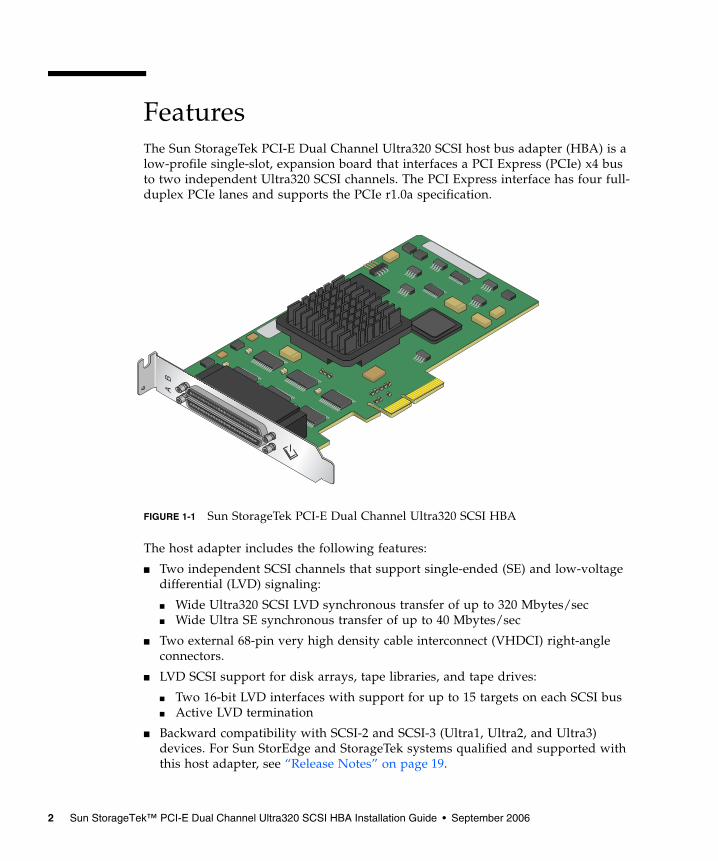
FeaturesThe Sun StorageTek PCI-E Dual Channel Ultra320 SCSI host bus adapter (HBA) is alow-profile single-slot, expansion board that interfaces a PCI Express (PCIe) x4 busto two independent Ultra320 SCSI channels. The PCI Express interface has four full-duplex PCIe lanes and supports the PCIe r1.0a specification.
FIGURE 1-1 Sun StorageTek PCI-E Dual Channel Ultra320 SCSI HBA
The host adapter includes the following features:
■ Two independent SCSI channels that support single-ended (SE) and low-voltagedifferential (LVD) signaling:
■ Wide Ultra320 SCSI LVD synchronous transfer of up to 320 Mbytes/sec■ Wide Ultra SE synchronous transfer of up to 40 Mbytes/sec
■ Two external 68-pin very high density cable interconnect (VHDCI) right-angleconnectors.
■ LVD SCSI support for disk arrays, tape libraries, and tape drives:
■ Two 16-bit LVD interfaces with support for up to 15 targets on each SCSI bus■ Active LVD termination
■ Backward compatibility with SCSI-2 and SCSI-3 (Ultra1, Ultra2, and Ultra3)devices. For Sun StorEdge and StorageTek systems qualified and supported withthis host adapter, see “Release Notes” on page 19.
2 Sun StorageTek™ PCI-E Dual Channel Ultra320 SCSI HBA Installation Guide • September 2006
■ Field programmable 512-Kbyte flash ROM (contains BIOS, FCode, and firmware)for booting in a Sun SPARC or Sun x64 processor-based host system.
■ RoHS compliant.
Supported Operating SystemsYou can use the Sun StorageTek PCI-E Dual Channel Ultra320 SCSI HBA with thefollowing operating systems (OSs):
■ Solaris 10 for SPARC
■ Solaris 10 for x64/x86
■ RHEL 3
■ RHEL 4
■ SLES 9
■ Windows Enterprise Server 2003
Installing the Host AdapterBefore you start, read these instructions, as well as the installation instructions forthe storage devices to be connected to the host adapter. Also, before installing thehost adapter, read “Release Notes” on page 19 for required information, includinglists of supported host systems, cables, and storage devices.
Caution – This host adapter is only for connection to a single-ended (SE) or low-voltage differential (LVD) device, and it does not work if connected to a high-voltagedifferential (HVD) device. See “SCSI Symbols” on page 33 for images of the SCSIsymbols.
▼ To Prepare for Hardware Installation1. Read and observe the safety information at the back of this book.
See “Safety Agency Compliance Statements” on page 45.
!
Chapter 1 Installing, Connecting, and Testing the Host Adapter 3
2. Install Solaris 10 HW2 (minimum version for SPARC) or Solaris 10 x86 HW1(minimum version for x86/x64) on the target host system.
Note – The version of the OS that can run on a particular host system is specific tothe host system. Refer to the host system documentation to determine the minimumrequired version of OS that can run on the target host system.
3. Download and install the latest Solaris 10 (either SPARC or x86) recommendedpatch cluster on the host, as described in “Release Notes” on page 19.
4. Install any required driver patches on the host, as described in “Release Notes” onpage 19.
Caution – If the driver and any required patches described in the release notes arenot installed, you might not be able to use the host adapter.
5. Install the SunVTS software on the host.
The SunVTS software is shipped on the Supplemental Software CD-ROM along withthe Solaris OS CD-ROM. Read the user’s guide listed in “Before You Read ThisBook” on page xi for instructions on installing the SunVTS software.
6. Exit the operating environment.
To inform any mounted users that the system will be going down, use the shutdowncommand. Otherwise, use the init 0 command. See the man pages for thesecommands or the Solaris AnswerBook documentation.
7. Power off the system.
For instructions, refer to the service documentation that came with your system.
# shutdown...ok
!
4 Sun StorageTek™ PCI-E Dual Channel Ultra320 SCSI HBA Installation Guide • September 2006
Caution – Damage to the HBA can occur as the result of careless handling orelectrostatic discharge (ESD). To minimize the possibility of ESD-related damage,use both a workstation anti-static mat and an ESD wrist strap. Observe the followingprecautions to avoid ESD-related problems:• Leave the HBA in its anti-static bag until you are ready to install it in the system.• Always use a properly fitted and grounded wrist strap or other suitable ESD
protection when handling the HBA, and observe proper ESD groundingtechniques.
• Hold the HBA by the edge of the PCB or mounting bracket, not by the connectors.• Place the HBA on a properly grounded anti-static work surface pad when it is out
of its protective anti-static bag.
You are now ready to unpack and install the host adapter as described in thefollowing text.
▼ To Unpack and Install the Host Adapter
1. Unpack the box containing the host adapter.
Note – Leave the host adapter in the protective bag until you are ready to install it.
!
Chapter 1 Installing, Connecting, and Testing the Host Adapter 5
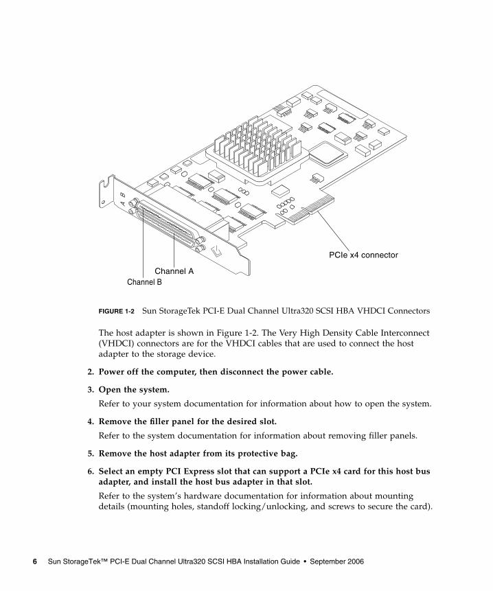
FIGURE 1-2 Sun StorageTek PCI-E Dual Channel Ultra320 SCSI HBA VHDCI Connectors
The host adapter is shown in Figure 1-2. The Very High Density Cable Interconnect(VHDCI) connectors are for the VHDCI cables that are used to connect the hostadapter to the storage device.
2. Power off the computer, then disconnect the power cable.
3. Open the system.
Refer to your system documentation for information about how to open the system.
4. Remove the filler panel for the desired slot.
Refer to the system documentation for information about removing filler panels.
5. Remove the host adapter from its protective bag.
6. Select an empty PCI Express slot that can support a PCIe x4 card for this host busadapter, and install the host bus adapter in that slot.
Refer to the system’s hardware documentation for information about mountingdetails (mounting holes, standoff locking/unlocking, and screws to secure the card).
PCIe x4 connector
Channel AChannel B
6 Sun StorageTek™ PCI-E Dual Channel Ultra320 SCSI HBA Installation Guide • September 2006
Caution – Using excessive force can bend or damage the host adapter edgeconnector. Make sure that the edge connector is properly aligned before pressing theadapter into place. The bracket around the two external connectors should fit intothe empty space where the filler panel was removed in Step 4.
7. If necessary, replace the low profile PCI bracket with a standard height PCIbracket in order to fit into a standard height PCI-E slot.
8. Close the system.
The next two sections describe how to connect the host adapter to one or morestorage devices and how to test the host adapter.
Connecting the Host AdapterBefore you connect the host adapter to the storage devices, do the following:
■ Refer to the release notes on page 19 for the lists of supported cables and storagedevices.
■ Refer to Appendix A, “Ultra320 SCSI Configuration” on page 31 for generalinformation on configuration for Ultra320 SCSI devices.
■ Refer to your system documentation and the storage device installation manualfor specific cabling and configuration instructions.
▼ To Connect SCSI Cables From the Host Adapterto the Storage Devices
● Connect the host adapter to the storage devices using the appropriate cables.
Testing the Host Adapter InstallationTo test the host adapter installation in a Solaris environment, use SPARC OBPprobe-scsi-all command, Solaris (SPARC or x64/x86) format command, orSunVTS disktest if the attached storage target is a disk array
!
Chapter 1 Installing, Connecting, and Testing the Host Adapter 7
▼ To Test the Installation Using the SPARC OBPprobe-scsi-all Command
Note – This procedure is not valid in a Solaris 10 for x64/x86 environment. Instead,you must use the format command to verify the installation of the Sun StorageTekPCI-E Dual Channel Ultra320 SCSI HBA before attempting to use it in a Solaris 10for x64/x86 environment.
1. If you have disconnected the power cable, reconnect it.
2. Power on the connected storage device, and then power on the host.
3. Bring the system down to the ok prompt at run level 0.
Note – If the host starts to reboot, interrupt the reboot process by pressing the Stopand A keys simultaneously.
4. At the ok prompt, issue the probe-scsi-all command to verify that the systemrecognizes the host adapter.
The probe-scsi-all command displays the SCSI devices connected to the host, asshown in the following screen example.
In this example, the first SCSI port (scsi@2) has one disk drive connected(Target 0). The second SCSI port (scsi@2,1) also has one disk drive connected(Target 0). In the illustration of the host adapter in FIGURE 1-2, the first SCSI port islabeled as Channel A; the second SCSI port as Channel B.
ok probe-scsi-all/pci@4,2000/pci@1/scsi@2Target 0Unit 0 DISK SEAGATE ST336605LSUN36G 0238/pci@4,2000/pci@1/scsi@2,1Target 0Unit 0 DISK SEAGATE ST336605LSUN36G 0238
8 Sun StorageTek™ PCI-E Dual Channel Ultra320 SCSI HBA Installation Guide • September 2006
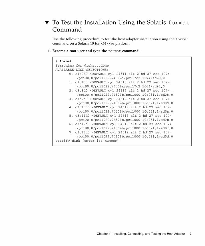
▼ To Test the Installation Using the Solaris formatCommandUse the following procedure to test the host adapter installation using the formatcommand on a Solaris 10 for x64/x86 platform.
1. Become a root user and type the format command.
# formatSearching for disks...doneAVAILABLE DISK SELECTIONS:
0. c1t0d0 <DEFAULT cyl 24611 alt 2 hd 27 sec 107>/pci@0,0/pci1022,7450@a/pci17c2,10@4/sd@0,0
1. c1t1d0 <DEFAULT cyl 24810 alt 2 hd 27 sec 107>/pci@0,0/pci1022,7450@a/pci17c2,10@4/sd@1,0
2. c3t8d0 <DEFAULT cyl 24619 alt 2 hd 27 sec 107>/pci@0,0/pci1022,7450@b/pci1000,10c0@1,1/sd@8,0
3. c3t9d0 <DEFAULT cyl 24619 alt 2 hd 27 sec 107>/pci@0,0/pci1022,7450@b/pci1000,10c0@1,1/sd@9,0
4. c3t10d0 <DEFAULT cyl 24619 alt 2 hd 27 sec 107>/pci@0,0/pci1022,7450@b/pci1000,10c0@1,1/sd@a,0
5. c3t11d0 <DEFAULT cyl 24619 alt 2 hd 27 sec 107>/pci@0,0/pci1022,7450@b/pci1000,10c0@1,1/sd@b,0
6. c3t12d0 <DEFAULT cyl 24619 alt 2 hd 27 sec 107>/pci@0,0/pci1022,7450@b/pci1000,10c0@1,1/sd@c,0
7. c3t13d0 <DEFAULT cyl 24619 alt 2 hd 27 sec 107>/pci@0,0/pci1022,7450@b/pci1000,10c0@1,1/sd@d,0
Specify disk (enter its number):
Chapter 1 Installing, Connecting, and Testing the Host Adapter 9
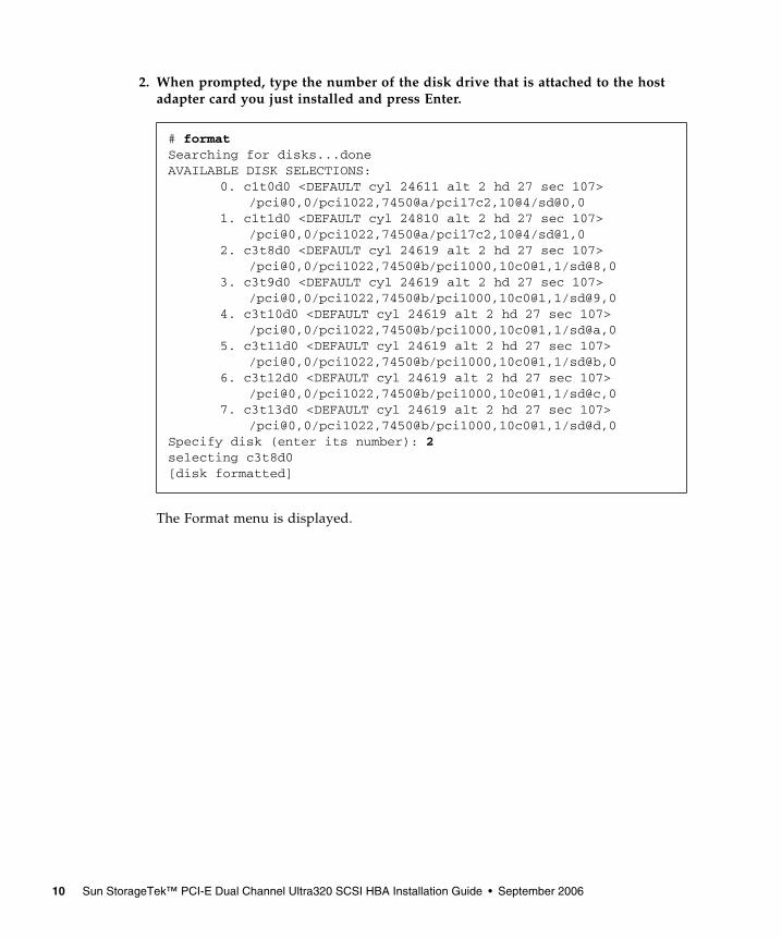
2. When prompted, type the number of the disk drive that is attached to the hostadapter card you just installed and press Enter.
The Format menu is displayed.
# formatSearching for disks...doneAVAILABLE DISK SELECTIONS:
0. c1t0d0 <DEFAULT cyl 24611 alt 2 hd 27 sec 107>/pci@0,0/pci1022,7450@a/pci17c2,10@4/sd@0,0
1. c1t1d0 <DEFAULT cyl 24810 alt 2 hd 27 sec 107>/pci@0,0/pci1022,7450@a/pci17c2,10@4/sd@1,0
2. c3t8d0 <DEFAULT cyl 24619 alt 2 hd 27 sec 107>/pci@0,0/pci1022,7450@b/pci1000,10c0@1,1/sd@8,0
3. c3t9d0 <DEFAULT cyl 24619 alt 2 hd 27 sec 107>/pci@0,0/pci1022,7450@b/pci1000,10c0@1,1/sd@9,0
4. c3t10d0 <DEFAULT cyl 24619 alt 2 hd 27 sec 107>/pci@0,0/pci1022,7450@b/pci1000,10c0@1,1/sd@a,0
5. c3t11d0 <DEFAULT cyl 24619 alt 2 hd 27 sec 107>/pci@0,0/pci1022,7450@b/pci1000,10c0@1,1/sd@b,0
6. c3t12d0 <DEFAULT cyl 24619 alt 2 hd 27 sec 107>/pci@0,0/pci1022,7450@b/pci1000,10c0@1,1/sd@c,0
7. c3t13d0 <DEFAULT cyl 24619 alt 2 hd 27 sec 107>/pci@0,0/pci1022,7450@b/pci1000,10c0@1,1/sd@d,0
Specify disk (enter its number): 2selecting c3t8d0[disk formatted]
10 Sun StorageTek™ PCI-E Dual Channel Ultra320 SCSI HBA Installation Guide • September 2006
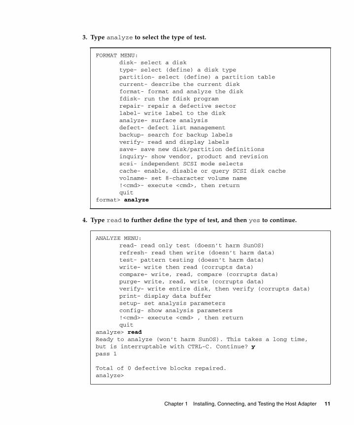
3. Type analyze to select the type of test.
4. Type read to further define the type of test, and then yes to continue.
FORMAT MENU:disk- select a disktype- select (define) a disk typepartition- select (define) a partition tablecurrent- describe the current diskformat- format and analyze the diskfdisk- run the fdisk programrepair- repair a defective sectorlabel- write label to the diskanalyze- surface analysisdefect- defect list managementbackup- search for backup labelsverify- read and display labelssave- save new disk/partition definitionsinquiry- show vendor, product and revisionscsi- independent SCSI mode selectscache- enable, disable or query SCSI disk cachevolname- set 8-character volume name!<cmd>- execute <cmd>, then returnquit
format> analyze
ANALYZE MENU:read- read only test (doesn’t harm SunOS)refresh- read then write (doesn’t harm data)test- pattern testing (doesn’t harm data)write- write then read (corrupts data)compare- write, read, compare (corrupts data)purge- write, read, write (corrupts data)verify- write entire disk, then verify (corrupts data)print- display data buffersetup- set analysis parametersconfig- show analysis parameters!<cmd>- execute <cmd> , then returnquit
analyze> readReady to analyze (won’t harm SunOS). This takes a long time,but is interruptable with CTRL-C. Continue? ypass 1
Total of 0 defective blocks repaired.analyze>
Chapter 1 Installing, Connecting, and Testing the Host Adapter 11
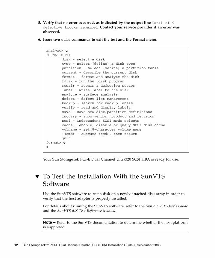
5. Verify that no error occurred, as indicated by the output line Total of 0defective blocks repaired. Contact your service provider if an error wasobserved.
6. Issue two quit commands to exit the test and the Format menu.
Your Sun StorageTek PCI-E Dual Channel Ultra320 SCSI HBA is ready for use.
▼ To Test the Installation With the SunVTSSoftwareUse the SunVTS software to test a disk on a newly attached disk array in order toverify that the host adapter is properly installed.
For details about running the SunVTS software, refer to the SunVTS 6.X User’s Guideand the SunVTS 6.X Test Reference Manual.
Note – Refer to the SunVTS documentation to determine whether the host platformis supported.
analyze> qFORMAT MENU:
disk - select a disk type - select (define) a disk type partition - select (define) a partition table current - describe the current disk format - format and analyze the disk fdisk - run the fdisk program repair - repair a defective sector label - write label to the disk analyze - surface analysis defect - defect list management backup - search for backup labels verify - read and display labels save - save new disk/partition definitions inquiry - show vendor, product and revision scsi - independent SCSI mode selects cache - enable, disable or query SCSI disk cache volname - set 8-character volume name !<cmd> - execute <cmd>, then return quit
format> q#
12 Sun StorageTek™ PCI-E Dual Channel Ultra320 SCSI HBA Installation Guide • September 2006
1. As superuser, open the SunVTS window.
2. From the System Map, select a disk drive that is in an array connected to the hostadapter.
3. Start the disk test.
4. Verify that no errors have occurred by checking the SunVTS status window.
5. If no problems occur, stop the SunVTS software.
Your host adapter is now ready to run applications.
Note – If problems occur, please contact your service provider for assistance.
Booting Through the Host AdapterThe Sun StorageTek PCI-E Dual Channel Ultra320 SCSI HBA uses the Solaris mptdevice driver, which is included in the Solaris 10 (SPARC or x64/x86) OS. Thisenables you to install Solaris 10 to a hard disk connected to the host adapter and'warm' boot directly from the disk.
Note – A “warm” boot requires that the hard disk attached to the host adapter bepowered on and available at the time the server is powered up. A “cold” boot, inwhich both the server and hard disk are powered up at the same time, is notsupported.
After booting, install any required patches for the mpt driver. Refer to “ReleaseNotes” on page 19 for instructions on downloading and installing mpt driverpatches.
# /opt/SUNWvts/bin/sunvts
Chapter 1 Installing, Connecting, and Testing the Host Adapter 13
Note – The Sun StorEdge 3310 standalone SCSI array is presently limited toUltra160 SCSI bus speeds only. Normally, the host adapter automatically lowers thetransfer speed for attached storage devices that are not Ultra320 capable. However,for the Sun StorEdge 3310 standalone SCSI array, you must create an mpt.conf fileto limit the Sun StorageTek PCI-E Dual Channel Ultra320 SCSI HBA to Ultra160 SCSIbus speeds. For instructions on creating the mpt.conf file, refer to the “ReleaseNotes” on page 19.
▼ To Boot an x86 Server From an Internal orExternal Disk Drive
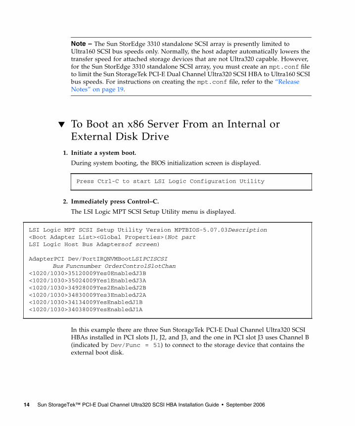
1. Initiate a system boot.
During system booting, the BIOS initialization screen is displayed.
2. Immediately press Control–C.
The LSI Logic MPT SCSI Setup Utility menu is displayed.
In this example there are three Sun StorageTek PCI-E Dual Channel Ultra320 SCSIHBAs installed in PCI slots J1, J2, and J3, and the one in PCI slot J3 uses Channel B(indicated by Dev/Func = 51) to connect to the storage device that contains theexternal boot disk.
Press Ctrl-C to start LSI Logic Configuration Utility
LSI Logic MPT SCSI Setup Utility Version MPTBIOS-5.07.03Description<Boot Adapter List><Global Properties>(Not partLSI Logic Host Bus Adaptersof screen)
AdapterPCI Dev/PortIRQNVMBootLSIPCISCSIBus Funcnumber OrderControlSlotChan
<1020/1030>35120009Yes0EnabledJ3B<1020/1030>35024009Yes1EnabledJ3A<1020/1030>34928009Yes2EnabledJ2B<1020/1030>34830009Yes3EnabledJ2A<1020/1030>34134009YesEnabledJ1B<1020/1030>34038009YesEnabledJ1A
14 Sun StorageTek™ PCI-E Dual Channel Ultra320 SCSI HBA Installation Guide • September 2006
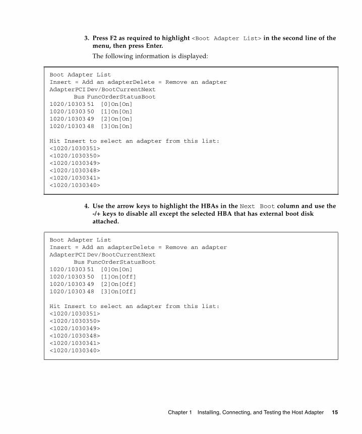
3. Press F2 as required to highlight <Boot Adapter List> in the second line of themenu, then press Enter.
The following information is displayed:
4. Use the arrow keys to highlight the HBAs in the Next Boot column and use the-/+ keys to disable all except the selected HBA that has external boot diskattached.
Boot Adapter ListInsert = Add an adapterDelete = Remove an adapterAdapterPCI Dev/BootCurrentNext
Bus FuncOrderStatusBoot1020/10303 51 [0]On[On]1020/10303 50 [1]On[On]1020/10303 49 [2]On[On]1020/10303 48 [3]On[On]
Hit Insert to select an adapter from this list:<1020/1030351><1020/1030350><1020/1030349><1020/1030348><1020/1030341><1020/1030340>
Boot Adapter ListInsert = Add an adapterDelete = Remove an adapterAdapterPCI Dev/BootCurrentNext
Bus FuncOrderStatusBoot1020/10303 51 [0]On[On]1020/10303 50 [1]On[Off]1020/10303 49 [2]On[Off]1020/10303 48 [3]On[Off]
Hit Insert to select an adapter from this list:<1020/1030351><1020/1030350><1020/1030349><1020/1030348><1020/1030341><1020/1030340>
Chapter 1 Installing, Connecting, and Testing the Host Adapter 15
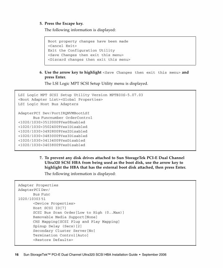
5. Press the Escape key.
The following information is displayed:
6. Use the arrow key to highlight <Save Changes then exit this menu> andpress Enter.
The LSI Logic MPT SCSI Setup Utility menu is displayed.
7. To prevent any disk drives attached to Sun StorageTek PCI-E Dual ChannelUltra320 SCSI HBA from being used as the boot disk, use the arrow key tohighlight the HBA that has the external boot disk attached, then press Enter.
The following information is displayed:
Boot property changes have been made<Cancel Exit>Exit the Configuration Utility<Save Changes then exit this menu><Discard changes then exit this menu>
LSI Logic MPT SCSI Setup Utility Version MPTBIOS-5.07.03<Boot Adapter List><Global Properties>LSI Logic Host Bus Adapters
AdapterPCI Dev/PortIRQNVMBootLSIBus Funcnumber OrderControl
<1020/1030>35120009Yes0Enabled<1020/1030>35024009Yes1Disabled<1020/1030>34928009Yes2Disabled<1020/1030>34830009Yes3Disabled<1020/1030>34134009YesDisabled<1020/1030>34038009YesDisabled
Adapter PropertiesAdapterPCI Dev/
Bus Func1020/10303 51
<Device Properties>Host SCSI ID[7]SCSI Bus Scan Order[Low to High (0..Max)]Removable Media Support[None]CHS Mapping[SCSI Plug and Play Mapping]Spinup Delay (Secs)[2]Secondary Cluster Server[No]Termination Control[Auto]<Restore Defaults>
16 Sun StorageTek™ PCI-E Dual Channel Ultra320 SCSI HBA Installation Guide • September 2006
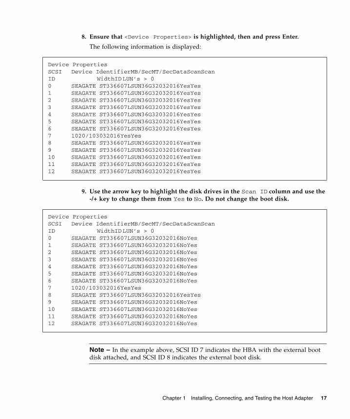
8. Ensure that <Device Properties> is highlighted, then and press Enter.
The following information is displayed:
9. Use the arrow key to highlight the disk drives in the Scan ID column and use the-/+ key to change them from Yes to No. Do not change the boot disk.
Note – In the example above, SCSI ID 7 indicates the HBA with the external bootdisk attached, and SCSI ID 8 indicates the external boot disk.
Device PropertiesSCSI Device IdentifierMB/SecMT/SecDataScanScanID WidthID LUN’s > 00 SEAGATE ST336607LSUN36G32032016YesYes1 SEAGATE ST336607LSUN36G32032016YesYes2 SEAGATE ST336607LSUN36G32032016YesYes3 SEAGATE ST336607LSUN36G32032016YesYes4 SEAGATE ST336607LSUN36G32032016YesYes5 SEAGATE ST336607LSUN36G32032016YesYes6 SEAGATE ST336607LSUN36G32032016YesYes7 1020/103032016YesYes8 SEAGATE ST336607LSUN36G32032016YesYes9 SEAGATE ST336607LSUN36G32032016YesYes10 SEAGATE ST336607LSUN36G32032016YesYes11 SEAGATE ST336607LSUN36G32032016YesYes12 SEAGATE ST336607LSUN36G32032016YesYes
Device PropertiesSCSI Device IdentifierMB/SecMT/SecDataScanScanID WidthID LUN’s > 00 SEAGATE ST336607LSUN36G32032016NoYes1 SEAGATE ST336607LSUN36G32032016NoYes2 SEAGATE ST336607LSUN36G32032016NoYes3 SEAGATE ST336607LSUN36G32032016NoYes4 SEAGATE ST336607LSUN36G32032016NoYes5 SEAGATE ST336607LSUN36G32032016NoYes6 SEAGATE ST336607LSUN36G32032016NoYes7 1020/103032016YesYes8 SEAGATE ST336607LSUN36G32032016YesYes9 SEAGATE ST336607LSUN36G32032016NoYes10 SEAGATE ST336607LSUN36G32032016NoYes11 SEAGATE ST336607LSUN36G32032016NoYes12 SEAGATE ST336607LSUN36G32032016NoYes
Chapter 1 Installing, Connecting, and Testing the Host Adapter 17
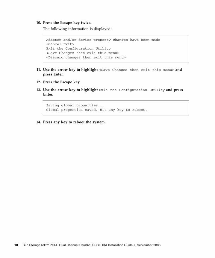
10. Press the Escape key twice.
The following information is displayed:
11. Use the arrow key to highlight <Save Changes then exit this menu> andpress Enter.
12. Press the Escape key.
13. Use the arrow key to highlight Exit the Configuration Utility and pressEnter.
14. Press any key to reboot the system.
Adapter and/or device property changes have been made<Cancel Exit>Exit the Configuration Utility<Save Changes then exit this menu><Discard changes then exit this menu>
Saving global properties...Global properties saved. Hit any key to reboot.
18 Sun StorageTek™ PCI-E Dual Channel Ultra320 SCSI HBA Installation Guide • September 2006
CHAPTER 2
Release Notes
This chapter contains the latest information about the Sun StorageTek PCI-E DualChannel Ultra320 SCSI HBA (host bus adapter), part number SG-XPCIE2SCSIU320Z.Read this document so that you are aware of issues or requirements that can affectthe installation and operation of the Sun StorageTek PCI-E Dual Channel Ultra320SCSI HBA.
This chapter contains the following sections:■ “Qualified Platforms” on page 19■ “Sun Solaris Operating Systems” on page 20■ “Linux Operating Systems” on page 20■ “Windows Server 2003 Operating System” on page 21■ “Storage Systems Support” on page 21■ “Qualified Cables” on page 22■ “Downloading and Installing the Patches and Documentation” on page 24■ “Known Issues” on page 28■ “Service Contact Information” on page 30
Note – Sun is not responsible for the availability of third-party web sites mentionedin this document. Sun does not endorse and is not responsible or liable for anycontent, advertising, products, or other materials that are available on or throughsuch sites or resources. Sun will not be responsible or liable for any actual or allegeddamage or loss caused by or in connection with the use of or reliance on any suchcontent, goods, or services that are available on or through such sites or resources.
Qualified PlatformsThis section lists the supported host platforms and minimum operating systemlevels the for Sun Solaris, Linux, and Windows operating environments.
19
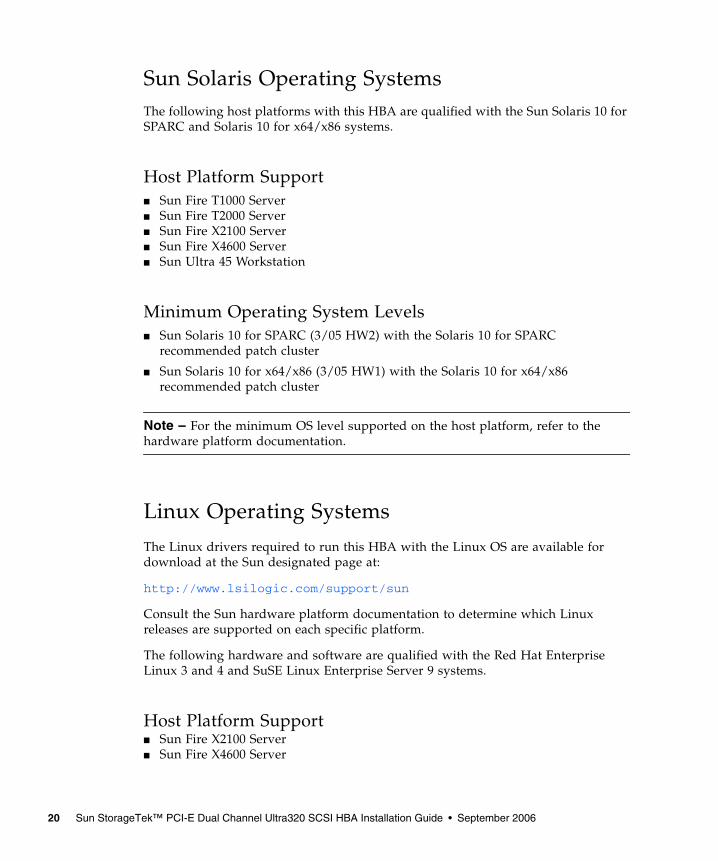
Sun Solaris Operating SystemsThe following host platforms with this HBA are qualified with the Sun Solaris 10 forSPARC and Solaris 10 for x64/x86 systems.
Host Platform Support■ Sun Fire T1000 Server■ Sun Fire T2000 Server■ Sun Fire X2100 Server■ Sun Fire X4600 Server■ Sun Ultra 45 Workstation
Minimum Operating System Levels■ Sun Solaris 10 for SPARC (3/05 HW2) with the Solaris 10 for SPARC
recommended patch cluster
■ Sun Solaris 10 for x64/x86 (3/05 HW1) with the Solaris 10 for x64/x86recommended patch cluster
Note – For the minimum OS level supported on the host platform, refer to thehardware platform documentation.
Linux Operating Systems
The Linux drivers required to run this HBA with the Linux OS are available fordownload at the Sun designated page at:
http://www.lsilogic.com/support/sun
Consult the Sun hardware platform documentation to determine which Linuxreleases are supported on each specific platform.
The following hardware and software are qualified with the Red Hat EnterpriseLinux 3 and 4 and SuSE Linux Enterprise Server 9 systems.
Host Platform Support■ Sun Fire X2100 Server■ Sun Fire X4600 Server
20 Sun StorageTek™ PCI-E Dual Channel Ultra320 SCSI HBA Installation Guide • September 2006
Minimum Operating System Levels■ Red Hat Enterprise Linux
■ Red Hat Enterprise Linux 3 (x64/AMD64) and (x86/IA32)
■ Red Hat Enterprise Linux 4 (x64/AMD64)
■ SuSE Linux Enterprise Server 9 for (x64/AMD64)
Windows Server 2003 Operating SystemThe host adapter device driver for Windows Server 2003 is available for download atthe Sun designated web page at:
http://www.lsilogic.com/support/sun
Consult the Sun hardware platform documentation to determine which Windowsreleases are supported.
The following hardware and software are qualified with the Windows Server 2003x86 and x64 systems.
Host Platform Support■ Sun Fire X2100 Server■ Sun Fire X4600 Server
Minimum Operating System Levels■ Windows Server 2003 (x86/IA32 and x64/AMD64)
Storage Systems SupportThe following storage systems are supported for all of the previously listedoperating systems.
Disk Storage Systems■ Sun StorageTek 3320 SCSI array (RAID and JBOD)
■ Sun StorageTek 3120 SCSI array (JBOD)
Chapter 2 Release Notes 21
■ Sun StorageTek 3310 SCSI array (RAID and JBOD)■ Sun StorageTek S1 array■ Sun StorEdge D2 array
Tape Backup Systems■ Sun StorageTek C2 tape library with LTO 2, LTO 3 or SDLT 600 tape drive
■ Sun StorageTek C4 tape library with LTO 2, LTO 3 or SDLT 600 tape drive
■ Sun StorEdge L8 tape autoloader with Sun StorageTek LTO LVD, LTO 2 (Gen 2)LVD, or SDLT 320 tape drive
■ Sun StorEdge L25/L100 tape library with Sun StorageTek LTO 1 (Gen 1) LVD,LTO 2 (Gen 2) LVD, LTO 3 (Gen 3) LVD, SDLT 320, or SDLT 600 tape drive
■ Sun StorEdge L180 tape library with LTO 1 (Gen 1) LVD, LTO 2 (Gen 2) LVD,LTO 3 (Gen 3) LVD, and SDLT320 LVD tape drives
■ Sun StorageTek StreamLine SL500 Modular Library System with LTO 2 (Gen 2)LVD and SDLT 320 LVD tape drives
■ Sun StorageTek C2 tape library with LTO 3 or SDLT 600 tape drive
■ Sun StorageTek C4 tape library with LTO 2, LTO 3 or SDLT 600 tape drive
■ Sun StorageTek DAT 72 desktop tape drive
■ Sun StorageTek LTO 2 (Gen 2) LVD desktop tape drive
■ Sun StorageTek LTO 3 (Gen 3) LVD desktop tape drive
■ Sun StorageTek SDLT 320 desktop tape drive
■ Sun StorageTek SDLT 600 desktop tape drive
Qualified CablesTABLE 2-1 lists the qualified cables for connecting the Sun StorEdge 3310 SCSI array,Sun StorageTek 3120 SCSI array, and Sun StorEdge D2 Array. TABLE 2-2 lists thequalified cables for connecting the Sun StorageTek S1 array to the Sun StorageTekPCI-E Dual Channel Ultra320 SCSI HBA.
22 Sun StorageTek™ PCI-E Dual Channel Ultra320 SCSI HBA Installation Guide • September 2006
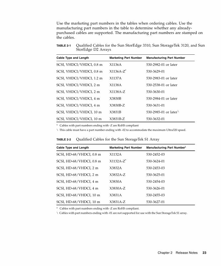
Use the marketing part numbers in the tables when ordering cables. Use themanufacturing part numbers in the table to determine whether any already-purchased cables are supported. The manufacturing part numbers are stamped onthe cables.
TABLE 2-1 Qualified Cables for the Sun StorEdge 3310, Sun StorageTek 3120, and SunStorEdge D2 Arrays
Cable Type and Length Marketing Part Number Manufacturing Part Number
SCSI, VHDCI/VHDCI, 0.8 m X1136A 530-2982-01 or later
SCSI, VHDCI/VHDCI, 0.8 m X1136A-Z*
* Cables with part numbers ending with -Z are RoHS compliant
530-3629-01
SCSI, VHDCI/VHDCI, 1.2 m X1137A 530-2983-01 or later
SCSI, VHDCI/VHDCI, 2 m X1138A 530-2538-01 or later
SCSI, VHDCI/VHDCI, 2 m X1138A-Z 530-3630-01
SCSI, VHDCI/VHDCI, 4 m X3830B 530-2984-01 or later
SCSI, VHDCI/VHDCI, 4 m X3830B-Z 530-3631-01
SCSI, VHDCI/VHDCI, 10 m X3831B 530-2985-01 or later\
\ This cable must have a part number ending with -02 to accommodate the maximum Ultra320 speed.
SCSI, VHDCI/VHDCI, 10 m X3831B-Z 530-3632-01
TABLE 2-2 Qualified Cables for the Sun StorageTek S1 Array
Cable Type and Length Marketing Part Number Manufacturing Part Number\
\ Cables with part numbers ending with -01 are not supported for use with the Sun StorageTek S1 array.
SCSI, HD-68/VHDCI, 0.8 m X1132A 530-2452-03
SCSI, HD-68/VHDCI, 0.8 m X1132A-Z*
* Cables with part numbers ending with -Z are RoHS compliant.
530-3624-01
SCSI, HD-68/VHDCI, 2 m X3832A 530-2453-03
SCSI, HD-68/VHDCI, 2 m X3832A-Z 530-3625-01
SCSI, HD-68/VHDCI, 4 m X3830A 530-2454-03
SCSI, HD-68/VHDCI, 4 m X3830A-Z 530-3626-01
SCSI, HD-68/VHDCI, 10 m X3831A 530-2455-03
SCSI, HD-68/VHDCI, 10 m X3831A-Z 530-3627-01
Chapter 2 Release Notes 23
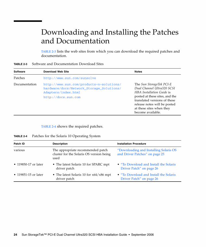
Downloading and Installing the Patchesand DocumentationTABLE 2-3 lists the web sites from which you can download the required patches anddocumentation.
TABLE 2-4 shows the required patches.
TABLE 2-3 Software and Documentation Download Sites
Software Download Web Site Notes
Patches http://www.sun.com/sunsolve
Documentation http://www.sun.com/products-n-solutions/hardware/docs/Network_Storage_Solutions/Adapters/index.html
http://docs.sun.com
The Sun StorageTek PCI-EDual Channel Ultra320 SCSIHBA Installation Guide isposted at these sites, and thetranslated versions of theserelease notes will be postedat these sites when theybecome available.
TABLE 2-4 Patches for the Solaris 10 Operating System
Patch ID Description Installation Procedure
various The appropriate recommended patchcluster for the Solaris OS version beingused
“Downloading and Installing Solaris OSand Driver Patches” on page 25
• 119850-17 or later • The latest Solaris 10 for SPARC mptdriver patch
• “To Download and Install the SolarisDriver Patch” on page 26
• 119851-15 or later • The latest Solaris 10 for x64/x86 mptdriver patch
• “To Download and Install the SolarisDriver Patch” on page 26
24 Sun StorageTek™ PCI-E Dual Channel Ultra320 SCSI HBA Installation Guide • September 2006
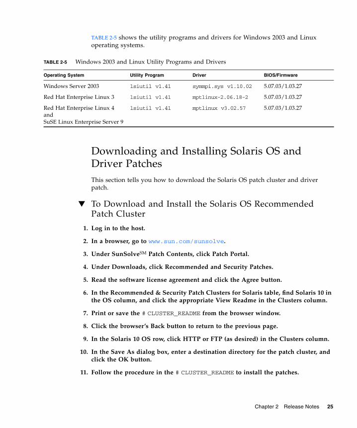
TABLE 2-5 shows the utility programs and drivers for Windows 2003 and Linuxoperating systems.
Downloading and Installing Solaris OS andDriver PatchesThis section tells you how to download the Solaris OS patch cluster and driverpatch.
▼ To Download and Install the Solaris OS RecommendedPatch Cluster
1. Log in to the host.
2. In a browser, go to www.sun.com/sunsolve.
3. Under SunSolveSM Patch Contents, click Patch Portal.
4. Under Downloads, click Recommended and Security Patches.
5. Read the software license agreement and click the Agree button.
6. In the Recommended & Security Patch Clusters for Solaris table, find Solaris 10 inthe OS column, and click the appropriate View Readme in the Clusters column.
7. Print or save the # CLUSTER_README from the browser window.
8. Click the browser’s Back button to return to the previous page.
9. In the Solaris 10 OS row, click HTTP or FTP (as desired) in the Clusters column.
10. In the Save As dialog box, enter a destination directory for the patch cluster, andclick the OK button.
11. Follow the procedure in the # CLUSTER_README to install the patches.
TABLE 2-5 Windows 2003 and Linux Utility Programs and Drivers
Operating System Utility Program Driver BIOS/Firmware
Windows Server 2003 lsiutil v1.41 symmpi.sys v1.10.02 5.07.03/1.03.27
Red Hat Enterprise Linux 3 lsiutil v1.41 mptlinux-2.06.18-2 5.07.03/1.03.27
Red Hat Enterprise Linux 4andSuSE Linux Enterprise Server 9
lsiutil v1.41 mptlinux v3.02.57 5.07.03/1.03.27
Chapter 2 Release Notes 25
▼ To Download and Install the Solaris Driver Patch
1. Log in to the host.
2. In a browser, go to www.sun.com/sunsolve.
3. Under SunSolve Patch Contents, click Patch Portal.
4. Under PatchFinder, enter the patch numbers from TABLE 2-4 for your specificSolaris release, and click the Find Patch button.
5. Print or save the patch instructions from the browser window.
6. Click either the HTTP or the FTP link in [Download Patch (nnn,nnn bytes)HTTP FTP].
7. In the Save As dialog box, enter a destination directory for the patch, and click theOK button.
Downloading and Installing the Linux Driver andFirmwareConsult the Sun hardware platform document to determine which Linux releases aresupported on your specific host platform.
▼ To Download and Install the Linux Driver
1. Log in to the host.
2. In a browser, go to www.lsilogic.com/support/sun.
3. Click to select SG-XPCIE2SCSIU320Z.
4. Click to select and download the Linux driver that is supported by the Linuxrelease (Red Hat Enterprise Linux or SuSE Linux Enterprise Server) on yourhardware platform.
5. Click to select and download the corresponding Readme file for the Linux driverand follow the instructions in the Readme to complete the driver installation.
▼ To Download and Update the Firmware
1. Log in to the host.
2. In a browser, go to www.lsilogic.com/support/sun.
26 Sun StorageTek™ PCI-E Dual Channel Ultra320 SCSI HBA Installation Guide • September 2006
3. Click to select SG-XPCIE2SCSIU320Z.
4. Under Utilities, click Linux to download the Linux utility program, lsiutil.
5. Under Firmware, click to download the firmware zip file and correspondingreadme file if posted Firmware/BIOS version is later than 1.03.27/5.07.03.
6. Unzip the firmware file and follow the instructions in the Readme file to updatethe firmware.
Downloading and Installing the Windows Server2003 Driver and FirmwareConsult the Sun hardware platform document to determine which Windows releasesare supported on your specific host platform.
▼ To Download and Install the Driver
1. Log in to the host.
2. In a browser, go to www.lsilogic.com/support/sun.
3. Click to select SG-XPCIE2SCSIU320Z.
4. Click to select and download the specific Windows driver that is supported by theWindows release on your hardware platform.
5. Click to select and download the corresponding Readme file for the Windowsdriver, and follow the instructions in the Readme file to complete the driverinstallation.
▼ To Download and Update the Firmware
1. Log in to the host.
2. In a browser, go to www.lsilogic.com/support/sun.
3. Click to select SG-XPCIE2SCSIU320Z.
4. Under Utilities, click Windows to download the Windows utility program,lsiutil, and the corresponding Readme file.
5. Under Firmware, click to download the firmware zip file and correspondingreadme file if posted Firmware/BIOS version is later than 1.03.27/5.07.03.
6. Unzip the firmware file and follow the instructions in the Readme file to updatethe firmware.
Chapter 2 Release Notes 27
Known IssuesThis section contains the currently known issues related to the Sun StorEdgePCI/PCI-X Dual Ultra320 SCSI host adapter.
Upgrading Firmware in a StorageTek 3120 SCSI Array Might Fail
Upgrading some older disk drive firmware in a Sun StorageTek 3120 SCSI arraymight fail if the older disk firmware does not correctly handle the Ultra320 SCSIprotocol.
Workaround–If this happens, perform the following steps.
1. Create a /kernel/drv/mpt.conf configuration file and insert the following lineinto it. This limits the Sun StorageTek PCI-E Dual Channel Ultra320 SCSI HBA tothe Ultra160 SCSI protocol.
2. Then reboot the system and perform the disk firmware upgrade. After completingthe upgrade, remove the inserted line from the /kernel/drv/mpt.conf file andreboot the system.
Supporting the StorEdge 3310 JBOD SCSI Array’s Ultra160 SCSI Speed
The Sun StorEdge 3310 JBOD SCSI array is only capable of running at the Ultra160SCSI speed.
Workaround–To limit the 3310 SCSI array to the Ultra160 SCSI speed and to supportup to 32 LUNS, perform the following steps.
1. Create a file called /kernel/drv/mpt.conf with the following lines in it:
2. Reboot the system.
scsi-options=0x1ff8;
device-type-scsi-options-list = "SUN StorEdge 3310", "SE3310-scsi-options";SE3310-scsi-options = 0x41ff8;
28 Sun StorageTek™ PCI-E Dual Channel Ultra320 SCSI HBA Installation Guide • September 2006
JBOD SCSI Arrays That Only Run at Ultra160 SCSI Speed
The StorEdge S1, D2, and D240 JBOD SCSI arrays are only capable of running at theUltra160 SCSI speed. During system boot, the driver may print a warning messageon the console during the speed negotiation.
Workaround–To prevent the warning message, perform the following step.
● Create a /kernel/drv/mpt.conf configuration file and insert the following line intoit. This limits the Sun StorageTek PCI-E Dual Channel Ultra320 SCSI HBA to theUltra160 SCSI protocol.
HBA Does Not Recognize LUN Numbers Greater Than 7■ 4994818–With OpenBoot™ PROM (OBP) commands, the Sun StorageTek PCI-E
Dual Channel Ultra320 SCSI HBA does not recognize any RAID LUN numbergreater than 7.
■ Workaround–Do not create a boot volume with a LUN (logical unit number)greater than 7.
BIOS Displays Only Eight LUNs■ 5053348–If more than eight LUNs are created in an array during system booting,
the BIOS displays only eight LUNs (LUN 0 through 7).
■ Workaround–Do not create a boot volume with a LUN number greater than 7.
Unrecognized Capability Messages■ 6441686–Unrecognized capability messages with SG-XPCIE2SCSIU320Z.
■ Workaround–The unrecognized capability messages are for information only. Youdo not need to take any action.
Error Message is an Indication of Error Recovery■ 6444814–'<unknown reason>': retrying command messages with
SG-XPCIE2SCSIU320Z (mpt) message indicates error recovery.
■ Workaround–Ignore this message as long as there is no I/O error.
scsi-options=0x1ff8;
Chapter 2 Release Notes 29
Service Contact InformationIf you need help installing or using this product in the United States, call1-800-USA-4SUN, or go to:
http://www.sun.com/service/contacting/index.html
30 Sun StorageTek™ PCI-E Dual Channel Ultra320 SCSI HBA Installation Guide • September 2006
APPENDIX A
Ultra320 SCSI Configuration
This appendix provides general information about Ultra320 SCSI configurationrules. This appendix discusses the following topics:
■ “Target Devices” on page 31■ “Bus Length” on page 32■ “Cabling and Termination” on page 33■ “SCSI Symbols” on page 33
Target DevicesFor Ultra320 SCSI performance of up to 320 Mbytes/sec, there can be a maximum of15 devices connected to each port on the host adapter.
The available target addresses (SCSI IDs) for each port on the host adapter are 0through F.
Note – SCSI ID 7 is reserved for the host adapter.
31
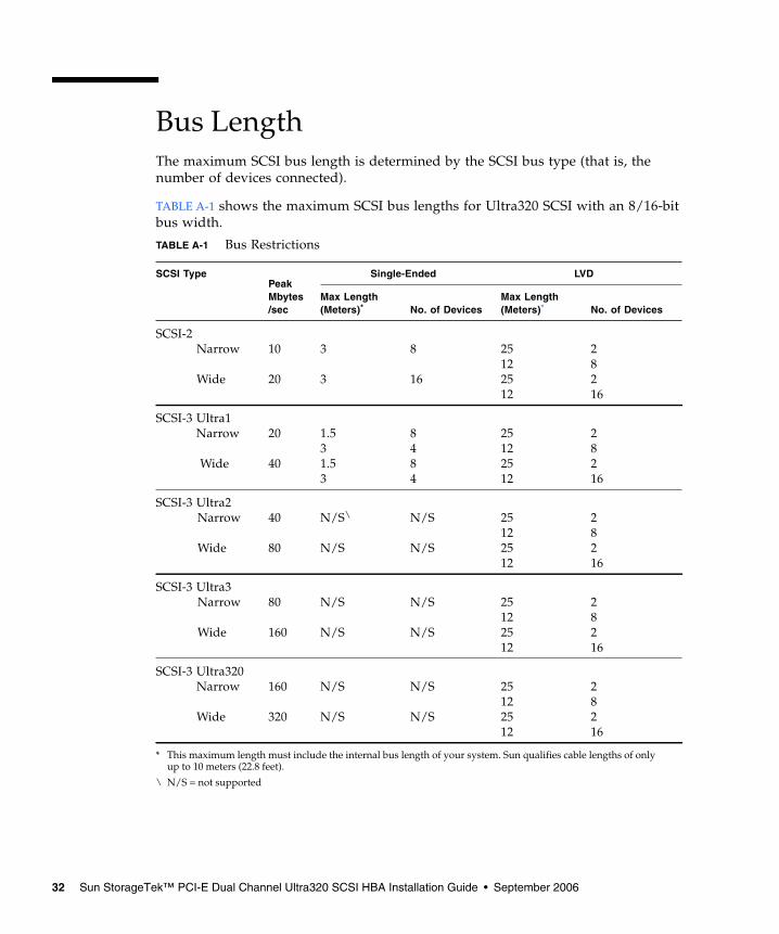
Bus LengthThe maximum SCSI bus length is determined by the SCSI bus type (that is, thenumber of devices connected).
TABLE A-1 shows the maximum SCSI bus lengths for Ultra320 SCSI with an 8/16-bitbus width.
TABLE A-1 Bus Restrictions
SCSI TypePeakMbytes/sec
Single-Ended LVD
Max Length(Meters)*
* This maximum length must include the internal bus length of your system. Sun qualifies cable lengths of onlyup to 10 meters (22.8 feet).
No. of DevicesMax Length(Meters)* No. of Devices
SCSI-2Narrow
Wide
10
20
3
3
8
16
25122512
28216
SCSI-3 Ultra1Narrow
Wide
20
40
1.531.53
8484
25122512
28216
SCSI-3 Ultra2Narrow
Wide
40
80
N/S\
N/S
\ N/S = not supported
N/S
N/S
25122512
28216
SCSI-3 Ultra3Narrow
Wide
80
160
N/S
N/S
N/S
N/S
25122512
28216
SCSI-3 Ultra320Narrow
Wide
160
320
N/S
N/S
N/S
N/S
25122512
28216
32 Sun StorageTek™ PCI-E Dual Channel Ultra320 SCSI HBA Installation Guide • September 2006
Cabling and TerminationIn order to maintain Ultra320 SCSI performance, all cables used must be Ultra320SCSI compliant. In addition, the SCSI bus must be correctly terminated. Most Sundevices use auto-termination. For more information, see the documentation thatcame with the device.
This host adapter has active terminators with an automatic means of enabling anddisabling the termination. The termination circuit derives its power from the PCI orSCSI bus. When the PCI bus power is removed, active SCSI termination ismaintained if the other SCSI device supplies power to the Term Pwr pins of the SCSIbus.
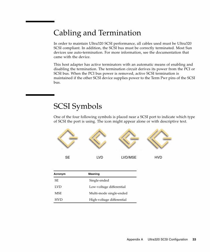
SCSI SymbolsOne of the four following symbols is placed near a SCSI port to indicate which typeof SCSI the port is using. The icon might appear alone or with descriptive text.
SE LVD LVD/MSE HVD
Acronym Meaning
SE Single-ended
LVD Low-voltage differential
MSE Multi-mode single-ended
HVD High-voltage differential
Appendix A Ultra320 SCSI Configuration 33

34 Sun StorageTek™ PCI-E Dual Channel Ultra320 SCSI HBA Installation Guide • September 2006
APPENDIX B
HBA Specifications
The chapter contains the specifications for the Sun StorageTek PCI-E Dual ChannelUltra320 SCSI HBA.
This appendix discusses the following topics:
■ “Physical Dimensions” on page 35■ “Power Requirements” on page 36■ “Performance Specifications” on page 36■ “PCIe Edge Connector Pin Definitions” on page 37■ “SCSI Connector Pin Definitions” on page 38
Physical Dimensions
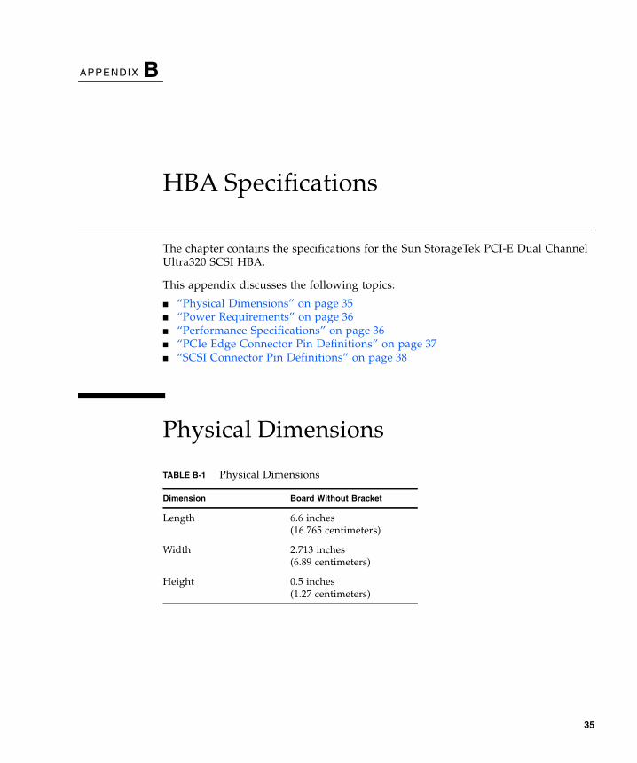
TABLE B-1 Physical Dimensions
Dimension Board Without Bracket
Length 6.6 inches(16.765 centimeters)
Width 2.713 inches(6.89 centimeters)
Height 0.5 inches(1.27 centimeters)
35
Power RequirementsThe power requirements are 12 volts 10%with a maximum current of 0.87 amps.
Performance Specifications
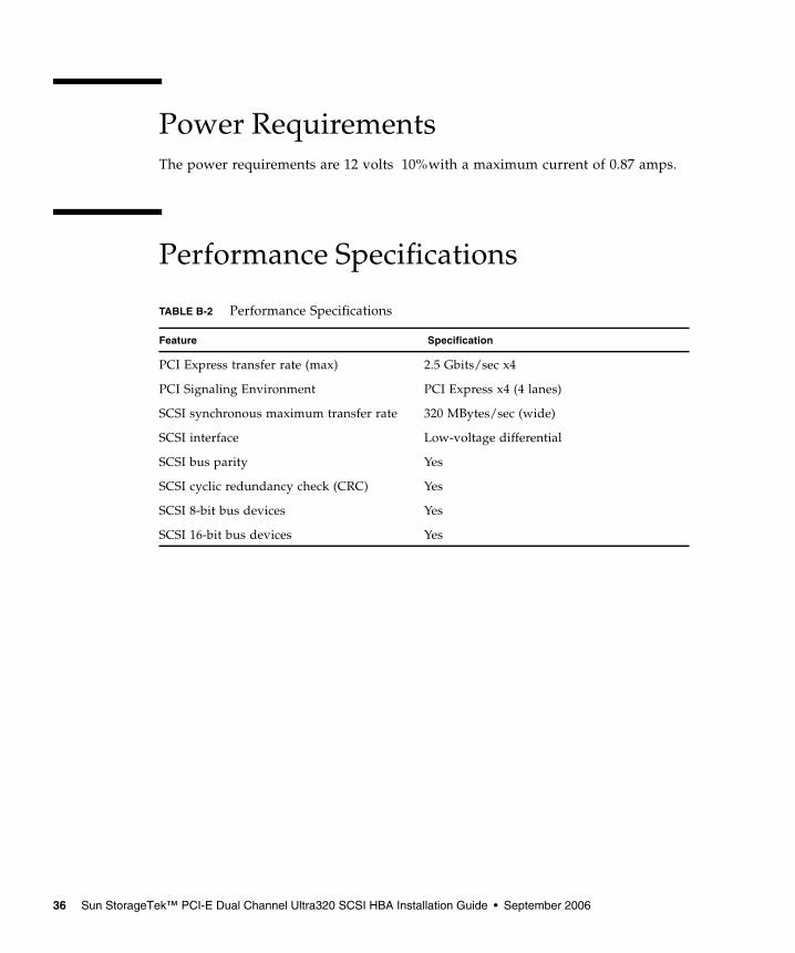
TABLE B-2 Performance Specifications
Feature Specification
PCI Express transfer rate (max) 2.5 Gbits/sec x4
PCI Signaling Environment PCI Express x4 (4 lanes)
SCSI synchronous maximum transfer rate 320 MBytes/sec (wide)
SCSI interface Low-voltage differential
SCSI bus parity Yes
SCSI cyclic redundancy check (CRC) Yes
SCSI 8-bit bus devices Yes
SCSI 16-bit bus devices Yes
36 Sun StorageTek™ PCI-E Dual Channel Ultra320 SCSI HBA Installation Guide • September 2006
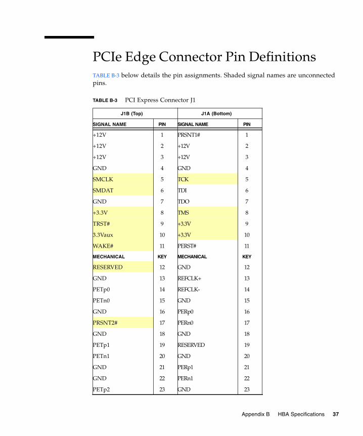
PCIe Edge Connector Pin DefinitionsTABLE B-3 below details the pin assignments. Shaded signal names are unconnectedpins.
TABLE B-3 PCI Express Connector J1
J1B (Top) J1A (Bottom)
SIGNAL NAME PIN SIGNAL NAME PIN
+12V 1 PRSNT1# 1
+12V 2 +12V 2
+12V 3 +12V 3
GND 4 GND 4
SMCLK 5 TCK 5
SMDAT 6 TDI 6
GND 7 TDO 7
+3.3V 8 TMS 8
TRST# 9 +3.3V 9
3.3Vaux 10 +3.3V 10
WAKE# 11 PERST# 11
MECHANICAL KEY MECHANICAL KEY
RESERVED 12 GND 12
GND 13 REFCLK+ 13
PETp0 14 REFCLK- 14
PETn0 15 GND 15
GND 16 PERp0 16
PRSNT2# 17 PERn0 17
GND 18 GND 18
PETp1 19 RESERVED 19
PETn1 20 GND 20
GND 21 PERp1 21
GND 22 PERn1 22
PETp2 23 GND 23
Appendix B HBA Specifications 37
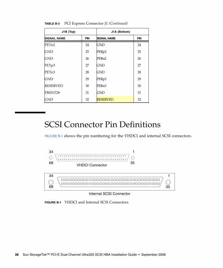
SCSI Connector Pin DefinitionsFIGURE B-1 shows the pin numbering for the VHDCI and internal SCSI connectors.
FIGURE B-1 VHDCI and Internal SCSI Connectors
J1B (Top) J1A (Bottom)
SIGNAL NAME PIN SIGNAL NAME PIN
PETn2 24 GND 24
GND 25 PERp2 25
GND 26 PERn2 26
PETp3 27 GND 27
PETn3 28 GND 28
GND 29 PERp3 29
RESERVED 30 PERn3 30
PRSNT2# 31 GND 31
GND 32 RESERVED 32
TABLE B-3 PCI Express Connector J1 (Continued)
1
35
34
68
1
35
34
68
VHDCI Connector
Internal SCSI Connector
38 Sun StorageTek™ PCI-E Dual Channel Ultra320 SCSI HBA Installation Guide • September 2006
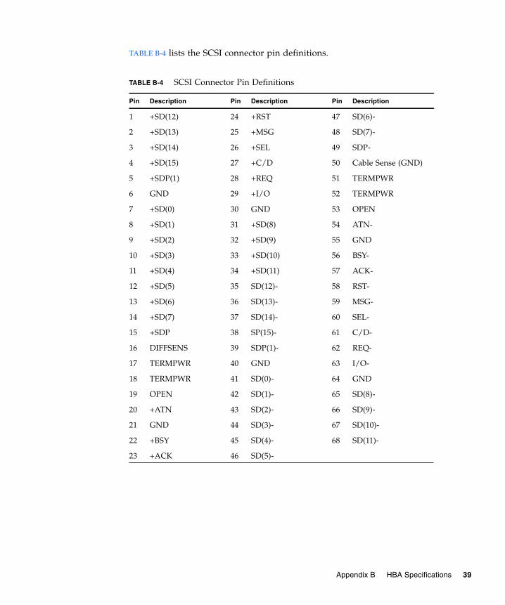
TABLE B-4 lists the SCSI connector pin definitions.
TABLE B-4 SCSI Connector Pin Definitions
Pin Description Pin Description Pin Description
1 +SD(12) 24 +RST 47 SD(6)-
2 +SD(13) 25 +MSG 48 SD(7)-
3 +SD(14) 26 +SEL 49 SDP-
4 +SD(15) 27 +C/D 50 Cable Sense (GND)
5 +SDP(1) 28 +REQ 51 TERMPWR
6 GND 29 +I/O 52 TERMPWR
7 +SD(0) 30 GND 53 OPEN
8 +SD(1) 31 +SD(8) 54 ATN-
9 +SD(2) 32 +SD(9) 55 GND
10 +SD(3) 33 +SD(10) 56 BSY-
11 +SD(4) 34 +SD(11) 57 ACK-
12 +SD(5) 35 SD(12)- 58 RST-
13 +SD(6) 36 SD(13)- 59 MSG-
14 +SD(7) 37 SD(14)- 60 SEL-
15 +SDP 38 SP(15)- 61 C/D-
16 DIFFSENS 39 SDP(1)- 62 REQ-
17 TERMPWR 40 GND 63 I/O-
18 TERMPWR 41 SD(0)- 64 GND
19 OPEN 42 SD(1)- 65 SD(8)-
20 +ATN 43 SD(2)- 66 SD(9)-
21 GND 44 SD(3)- 67 SD(10)-
22 +BSY 45 SD(4)- 68 SD(11)-
23 +ACK 46 SD(5)-
Appendix B HBA Specifications 39

40 Sun StorageTek™ PCI-E Dual Channel Ultra320 SCSI HBA Installation Guide • September 2006
APPENDIX C
Declaration of Conformity,Regulatory Compliance, and SafetyStatements
This appendix contains information that applies to the Sun StorageTek PCI-E DualChannel Ultra320 SCSI HBA. This appendix discusses the following topics:
■ “Declaration of Conformity” on page 42■ “Regulatory Compliance Statements” on page 43■ “Safety Agency Compliance Statements” on page 45
41
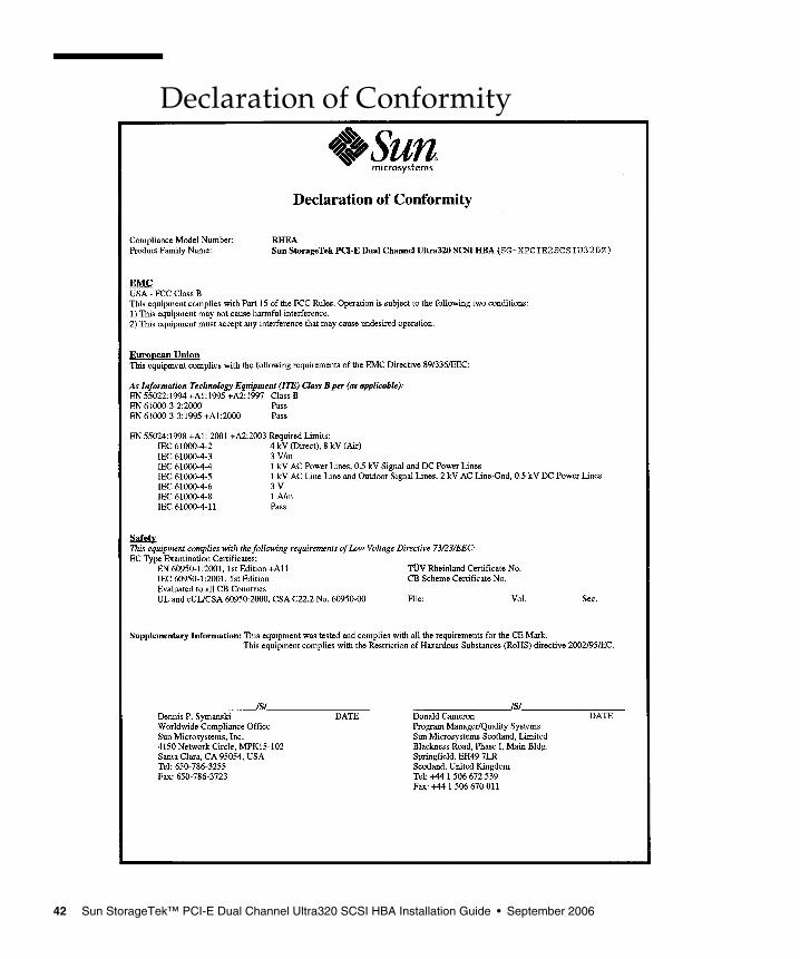
Declaration of Conformity
42 Sun StorageTek™ PCI-E Dual Channel Ultra320 SCSI HBA Installation Guide • September 2006
Regulatory Compliance StatementsYour Sun product is marked to indicate its compliance class:
• Federal Communications Commission (FCC) — USA• Department of Communications (DOC) — Canada• Voluntary Control Council for Interference (VCCI) — Japan
Please read the appropriate section that corresponds to the marking on your Sun product before attempting to install theproduct.
FCC Class A NoticeThis device complies with Part 15 of the FCC Rules. Operation is subject to the following two conditions:
1. This device may not cause harmful interference.2. This device must accept any interference received, including interference that may cause undesired operation.
Note: This equipment has been tested and found to comply with the limits for a Class A digital device, pursuant to Part 15 ofthe FCC Rules. These limits are designed to provide reasonable protection against harmful interference when the equipmentis operated in a commercial environment. This equipment generates, uses and can radiate radio frequency energy and, if notinstalled and used in accordance with the instruction manual, may cause harmful interference to radio communications.Operation of this equipment in a residential area is likely to cause harmful interference in which case the user will be requiredto correct the interference at his own expense.
Shielded Cables: Connections between the workstation and peripherals must be made using shielded cables in order tomaintain compliance with FCC radio frequency emission limits. Networking connections can be made using unshieldedtwisted-pair (UTP) cables.
Modifications: Any modifications made to this device that are not approved by Sun Microsystems, Inc. may void theauthority granted to the user by the FCC to operate this equipment.
FCC Class B NoticeThis device complies with Part 15 of the FCC Rules. Operation is subject to the following two conditions:
1. This device may not cause harmful interference.2. This device must accept any interference received, including interference that may cause undesired operation.
Note: This equipment has been tested and found to comply with the limits for a Class B digital device, pursuant to Part 15 ofthe FCC Rules. These limits are designed to provide reasonable protection against harmful interference in a residentialinstallation. This equipment generates, uses and can radiate radio frequency energy and, if not installed and used inaccordance with the instructions, may cause harmful interference to radio communications. However, there is no guaranteethat interference will not occur in a particular installation. If this equipment does cause harmful interference to radio ortelevision reception, which can be determined by turning the equipment off and on, the user is encouraged to try to correctthe interference by one or more of the following measures:
• Reorient or relocate the receiving antenna.• Increase the separation between the equipment and receiver.• Connect the equipment into an outlet on a circuit different from that to which the receiver is connected.• Consult the dealer or an experienced radio/television technician for help.
Appendix C Declaration of Conformity, Regulatory Compliance, and Safety Statements 43
Shielded Cables: Connections between the workstation and peripherals must be made using shielded cables in order tomaintain compliance with FCC radio frequency emission limits. Networking connections can be made using unshieldedtwisted pair (UTP) cables.
Modifications: Any modifications made to this device that are not approved by Sun Microsystems, Inc. may void theauthority granted to the user by the FCC to operate this equipment.
44 Sun StorageTek™ PCI-E Dual Channel Ultra320 SCSI HBA Installation Guide • September 2006
Safety Agency ComplianceStatementsRead this section before beginning any procedure. Thefollowing text provides safety precautions to follow wheninstalling a Sun Microsystems product.
Safety PrecautionsFor your protection, observe the following safetyprecautions when setting up your equipment:
■ Follow all cautions and instructions marked on theequipment.
■ Ensure that the voltage and frequency of your powersource match the voltage and frequency inscribed onthe equipment’s electrical rating label.
■ Never push objects of any kind through openings inthe equipment. Dangerous voltages may be present.Conductive foreign objects could produce a shortcircuit that could cause fire, electric shock, or damageto your equipment.
SymbolsThe following symbols may appear in this book:
Caution – There is a risk of personal injuryand equipment damage. Follow theinstructions.
Caution – Hot surface. Avoid contact.Surfaces are hot and may cause personalinjury if touched.
Caution – Hazardous voltages are present.To reduce the risk of electric shock and dangerto personal health, follow the instructions.
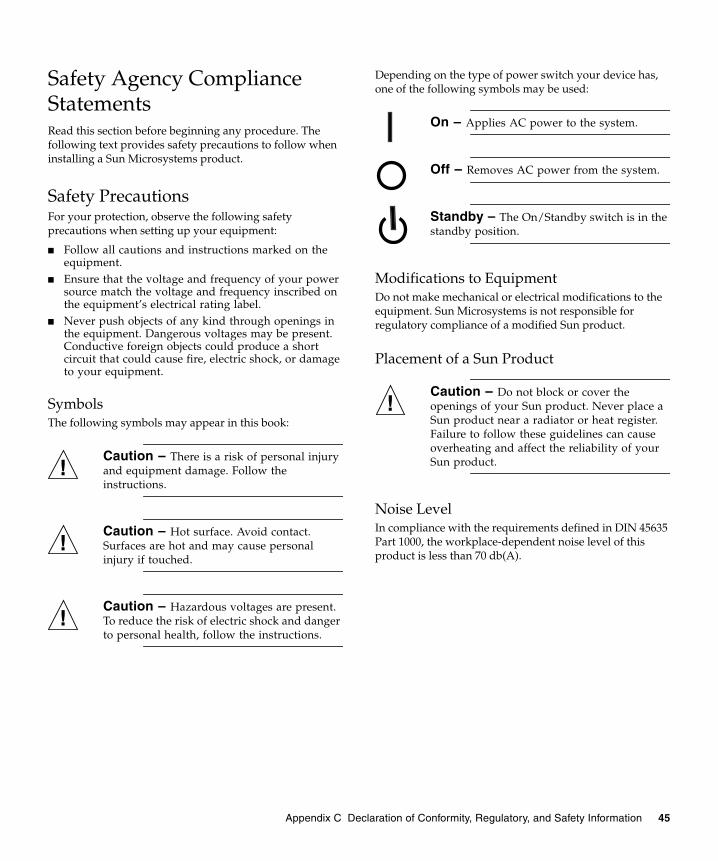
Depending on the type of power switch your device has,one of the following symbols may be used:
On – Applies AC power to the system.
Off – Removes AC power from the system.
Standby – The On/Standby switch is in thestandby position.
Modifications to EquipmentDo not make mechanical or electrical modifications to theequipment. Sun Microsystems is not responsible forregulatory compliance of a modified Sun product.
Placement of a Sun Product
Caution – Do not block or cover theopenings of your Sun product. Never place aSun product near a radiator or heat register.Failure to follow these guidelines can causeoverheating and affect the reliability of yourSun product.
Noise LevelIn compliance with the requirements defined in DIN 45635Part 1000, the workplace-dependent noise level of thisproduct is less than 70 db(A).
Appendix C Declaration of Conformity, Regulatory, and Safety Information 45
SELV ComplianceSafety status of I/O connections comply to SELVrequirements.
Power Cord Connection
Caution – Sun products are designed towork with power systems having a groundedneutral (grounded return for DC-poweredproducts). To reduce the risk of electric shock,do not plug Sun products into any other typeof power system. Contact your facilitiesmanager or a qualified electrician if you arenot sure what type of power is supplied toyour building.
Caution – Not all power cords have thesame current ratings. Do not use the powercord provided with your equipment for anyother products or use. Household extensioncords do not have overload protection and arenot meant for use with computer systems. Donot use household extension cords with yourSun product.
The following caution applies only to devices with aStandby power switch:
Caution – The power switch of this productfunctions as a standby type device only. Thepower cord serves as the primary disconnectdevice for the system. Be sure to plug thepower cord into a grounded power outlet thatis nearby the system and is readily accessible.Do not connect the power cord when thepower supply has been removed from thesystem chassis.
The following caution applies only to devices with multiplepower cords:
Caution – For products with multiplepower cords, all power cords must bedisconnected to completely remove powerfrom the system.
Battery Warning
Caution – There is danger of explosion ifbatteries are mishandled or incorrectlyreplaced. On systems with replaceablebatteries, replace only with the samemanufacturer and type or equivalent typerecommended by the manufacturer per theinstructions provided in the product servicemanual. Do not disassemble batteries orattempt to recharge them outside the system.Do not dispose of batteries in fire. Dispose ofbatteries properly in accordance with themanufacturer’s instructions and localregulations. Note that on Sun CPU boards,there is a lithium battery molded into the real-time clock. These batteries are not customerreplaceable parts.
System Unit CoverYou must remove the cover of your Sun computer systemunit to add cards, memory, or internal storage devices. Besure to replace the cover before powering on your computersystem.
Caution – Do not operate Sun productswithout the cover in place. Failure to take thisprecaution may result in personal injury andsystem damage.
46 Sun StorageTek™ PCI-E Dual Channel Ultra320 SCSI HBA Installation Guide • September 2006
Rack System WarningThe following warnings apply to Racks and Rack Mountedsystems.
Caution – For safety, equipment shouldalways be loaded from the bottom up. That is,install the equipment that will be mounted inthe lowest part of the rack first, then the nexthigher systems, etc.
Caution – To prevent the rack from tippingduring equipment installation, the anti-tilt baron the rack must be deployed.
Caution – To prevent extreme operatingtemperature within the rack insure that themaximum temperature does not exceed theproduct’s ambient rated temperatures.
Caution – To prevent extreme operatingtemperatures due to reduced airflowconsideration should be made to the amountof air flow that is required for a safe operationof the equipment.
Laser Compliance NoticeSun products that use laser technology comply with Class 1laser requirements.
CD and DVD DevicesThe following caution applies to CD, DVD, and otheroptical devices.
Caution – Use of controls, adjustments, orthe performance of procedures other thanthose specified herein may result in hazardousradiation exposure.
Conformité aux normes de sécuritéVeuillez lire attentivement cette section avant decommencer. Ce texte traite des mesures de sécurité qu’ilconvient de prendre pour l’installation d’un produit SunMicrosystems.
Mesures de sécuritéPour votre sécurité, nous vous recommandons de suivrescrupuleusement les mesures de sécurité ci-dessous lorsquevous installez votre matériel:
■ Suivez tous les avertissements et toutes lesinstructions inscrites sur le matériel.
■ Assurez-vous que la tension et la fréquence de votresource d'alimentation correspondent à la tension et àla fréquence indiquées sur l'étiquette de la tensionélectrique nominale du matériel
■ N'introduisez jamais d'objets quels qu'ils soient dansles ouvertures de l'équipement. Vous pourriez voustrouver en présence de hautes tensions dangereuses.Tout objet étranger conducteur risque de produire uncourt-circuit pouvant présenter un risque d'incendieou de décharge électrique, ou susceptibled'endommager le matériel.
SymbolesVous trouverez ci-dessous la signification des différentssymboles utilisés:
Attention – Vous risquez d'endommager lematériel ou de vous blesser. Veuillez suivre lesinstructions.
Attention – Surfaces brûlantes. Evitez toutcontact. Les surfaces sont brûlantes. Vousrisquez de vous blesser si vous les touchez.
Class 1 Laser ProductLuokan 1 Laserlaite
Klasse 1 Laser ApparatLaser Klasse 1
Appendix C Declaration of Conformity, Regulatory, and Safety Information 47
Attention – Tensions dangereuses. Pourréduire les risques de décharge électrique etde danger physique, observez les consignesindiquées.
Selon le type d'interrupteur marche/arrêt dont votreappareil est équipé, l'un des symboles suivants sera utilisé:
Marche – Met le système sous tensionalternative.
Arret – Met le système hors tensionalternative.
Veilleuse – L'interrupteur Marche/Veilleest sur la position de veille.
Modification du matérielN'apportez aucune modification mécanique ou électriqueau matériel. Sun Microsystems décline toute responsabilitéquant à la non-conformité éventuelle d'un produit Sunmodifié.
Positionnement d’un produit Sun
Attention – Evitez d'obstruer ou derecouvrir les orifices de votre produit Sun.N'installez jamais un produit Sun près d'unradiateur ou d'une source de chaleur. Si vousne respectez pas ces consignes, votre produitSun risque de surchauffer et sonfonctionnement en sera altéré.
Niveau de pression acoustiqueLe niveau de pression acoustique du lieu de travail définiepar la norme DIN 45 635 Part 1000 doit être au maximum de70 db(A).
Conformité SELVLe niveau de sécurité des connexions E/S est conforme auxnormes SELV.
Connexion du cordon d’alimentation
Attention – Les produits Sun sont conçuspour fonctionner avec des systèmesd'alimentation équipés d'un conducteurneutre relié à la terre (conducteur neutre pourproduits alimentés en CC). Pour réduire lesrisques de décharge électrique, ne branchezjamais les produits Sun sur une sourced'alimentation d'un autre type. Contactez legérant de votre bâtiment ou un électricienagréé si vous avez le moindre doute quant autype d'alimentation fourni dans votrebâtiment.
Attention – Tous les cordons d'alimentationne présentent pas les mêmes caractéristiquesélectriques. Les cordons d'alimentation àusage domestique ne sont pas protégés contreles surtensions et ne sont pas conçus pour êtreutilisés avec des ordinateurs. N'utilisez jamaisde cordon d'alimentation à usage domestiqueavec les produits Sun.
L'avertissement suivant s'applique uniquement auxsystèmes équipés d'un interrupteur Veille:
Attention – L'interrupteur d'alimentationde ce produit fonctionne uniquement commeun dispositif de mise en veille. Le cordond'alimentation constitue le moyen principal dedéconnexion de l'alimentation pour lesystème. Assurez-vous de le brancher dansune prise d'alimentation mise à la terre prèsdu système et facile d'accès. Ne le branchezpas lorsque l'alimentation électrique ne setrouve pas dans le châssis du système.
L'avertissement suivant s'applique uniquement auxsystèmes équipés de plusieurs cordons d'alimentation:
Attention – Pour mettre un système équipéde plusieurs cordons d'alimentation horstension, il est nécessaire de débrancher tousles cordons d'alimentation.
48 Sun StorageTek™ PCI-E Dual Channel Ultra320 SCSI HBA Installation Guide • September 2006
Mise en garde relative aux batteries
Attention – Les batteries risquentd’exploser en cas de manipulation maladroiteou de remplacement incorrect. Pour lessystèmes dont les batteries sont remplaçables,effectuez les remplacements uniquement selonle modèle du fabricant ou un modèleéquivalent recommandé par le fabricant,conformément aux instructions fournies dansle manuel de service du système. N’essayez enaucun cas de démonter les batteries, ni de lesrecharger hors du système. Ne les jetez pas aufeu. Mettez-les au rebut selon les instructionsdu fabricant et conformément à la législationlocale en vigueur. Notez que sur les cartesprocesseur de Sun, une batterie au lithium aété moulée dans l'horloge temps réel. Lesbatteries ne sont pas des pièces remplaçablespar le client.
Couvercle de l'unitéPour ajouter des cartes, de la mémoire ou des périphériquesde stockage internes, vous devez retirer le couvercle devotre système Sun. Remettez le couvercle supérieur enplace avant de mettre votre système sous tension.
Attention – Ne mettez jamais des produitsSun sous tension si leur couvercle supérieurn'est pas mis en place. Si vous ne prenez pasces précautions, vous risquez de vous blesserou d'endommager le système.
Mise en garde relative au système en rackLa mise en garde suivante s'applique aux racks et auxsystèmes montés en rack.
Attention – Pour des raisons de sécurité, lematériel doit toujours être chargé du bas versle haut. En d'autres termes, vous devezinstaller, en premier, le matériel qui doit setrouver dans la partie la plus inférieure durack, puis installer le matériel sur le niveausuivant, etc.
Attention – Afin d'éviter que le rack nepenche pendant l'installation du matériel, tirezla barre anti-basculement du rack.
Attention – Pour éviter des températures defonctionnement extrêmes dans le rack,assurez-vous que la température maximale nedépasse pas la fourchette de températuresambiantes du produit déterminée par lefabricant.
Attention – Afin d'empêcher destempératures de fonctionnement extrêmesprovoquées par une aération insuffisante,assurez-vous de fournir une aérationappropriée pour un fonctionnement dumatériel en toute sécurité
Avis de conformité des appareils laserLes produits Sun qui font appel aux technologies lasers sontconformes aux normes de la classe 1 en la matière.
Périphériques CD et DVDL'avertissement suivant s'applique aux périphériques CD,DVD et autres périphériques optiques:
Attention – L'utilisation de contrôles et deréglages ou l'application de procédures autresque ceux spécifiés dans le présent documentpeuvent entraîner une exposition à desradiations dangereuses.
Class 1 Laser ProductLuokan 1 Laserlaite
Klasse 1 Laser ApparatLaser Klasse 1
Appendix C Declaration of Conformity, Regulatory, and Safety Information 49
Einhaltung sicherheitsbehördlicherVorschriftenLesen Sie vor dem Ausführen von Arbeiten diesenAbschnitt. Im folgenden Text werden Sicherheitsvor-kehrungen beschrieben, die Sie bei der Installation einesSun Microsystems-Produkts beachten müssen.
SicherheitsvorkehrungenTreffen Sie zu Ihrem eigenen Schutz bei der Installation desGeräts die folgenden Sicherheitsvorkehrungen:
■ Beachten Sie alle auf den Geräten angebrachtenWarnhinweise und Anweisungen.
■ Stellen Sie sicher, dass Spannung und Frequenz derStromversorgung den Nennleistungen auf dem amGerät angebrachten Etikett entsprechen.
■ Führen Sie niemals Fremdobjekte in die Öffnungenam Gerät ein. Es können gefährliche Spannungenanliegen. Leitfähige Fremdobjekte können einenKurzschluss verursachen, der einen Brand, Strom-schlag oder Geräteschaden herbeiführen kann.
SymboleDie Symbole in diesem Handbuch haben folgendeBedeutung:
Achtung – Gefahr von Verletzung undGeräteschaden. Befolgen Sie die Anwei-sungen.
Achtung – Heiße Oberfläche. Nichtberühren, da Verletzungsgefahr durch heißeOberfläche besteht.
Achtung – Gefährliche Spannungen.Befolgen Sie die Anweisungen, umStromschläge und Verletzungen zu vermeiden.
Je nach Netzschaltertyp an Ihrem Gerät kann eines derfolgenden Symbole verwendet werden:
Ein – Versorgt das System mit Wechselstrom.
Aus– Unterbricht die Wechselstromzufuhrzum Gerät.
Wartezustand – Der Ein-/Standby-Netz-schalter befindet sich in der Standby-Position.
Modifikationen des GerätsNehmen Sie keine elektrischen oder mechanischenGerätemodifikationen vor. Sun Microsystems ist für dieEinhaltung der Sicherheitsvorschriften von modifiziertenSun-Produkten nicht haftbar.
Aufstellung von Sun-Geräten
Achtung – Geräteöffnungen Ihres Sun-Produkts dürfen nicht blockiert oderabgedeckt werden. Sun-Geräte sollten niemalsin der Nähe von Heizkörpern oder Heißluft-klappen aufgestellt werden. Die Nichtbeach-tung dieser Richtlinien kann Überhitzungverursachen und die Zuverlässigkeit IhresSun-Geräts beeinträchtigen.
LautstärkeGemäß den in DIN 45 635 Teil 1000 definierten Vorschriftenbeträgt die arbeitsplatzbedingte Lautstärke dieses Produktsweniger als 70 dB(A).
SELV-KonformitätDer Sicherheitsstatus der E/A-Verbindungen entsprichtden SELV-Anforderungen.
50 Sun StorageTek™ PCI-E Dual Channel Ultra320 SCSI HBA Installation Guide • September 2006
Anschluss des Netzkabels
Achtung – Sun-Geräte sind fürStromversorgungssysteme mit einemgeerdeten neutralen Leiter (geerdeterRückleiter bei gleichstrombetriebenenGeräten) ausgelegt. Um die Gefahr vonStromschlägen zu vermeiden, schließen Siedas Gerät niemals an andere Stromversor-gungssysteme an. Wenden Sie sich an denzuständigen Gebäudeverwalter oder an einenqualifizierten Elektriker, wenn Sie nicht sicherwissen, an welche Art von Stromversor-gungssystem Ihr Gebäude angeschlossen ist.
Achtung – Nicht alle Netzkabel verfügenüber die gleichen Nennwerte. Herkömmliche,im Haushalt verwendete Verlängerungskabelbesitzen keinen Überlastschutz und sinddaher für Computersysteme nicht geeignet.Verwenden Sie bei Ihrem Sun-Produkt keineHaushalts-Verlängerungskabel.
Die folgende Warnung gilt nur für Geräte mit Standby-Netzschalter:
Achtung – Beim Netzschalter dieses Gerätshandelt es sich nur um einen Ein/Standby-Schalter. Zum völligen Abtrennen des Systemsvon der Stromversorgung dient hauptsächlichdas Netzkabel. Stellen Sie sicher, dass dasNetzkabel an eine frei zugängliche geerdeteSteckdose in der Nähe des Systems ange-schlossen ist. Schließen Sie das Stromkabelnicht an, wenn die Stromversorgung vomSystemchassis entfernt wurde.
Die folgende Warnung gilt nur für Geräte mit mehrerenNetzkabeln:
Achtung – Bei Produkten mit mehrerenNetz-kabeln müssen alle Netzkabel abgetrenntwer-den, um das System völlig von derStromver-sorgung zu trennen.
Warnung bezüglich Batterien
Achtung – Bei unsachgemäßerHandhabung oder nicht fachgerechtemAustausch der Batterien bestehtExplosionsgefahr. Verwen-den Sie beiSystemen mit austauschbaren Batterienausschließlich Ersatzbatterien desselben Typsund Herstellers bzw. einen entsprechenden,vom Hersteller gemäß den Anweisungen imService-Handbuch des Produkts empfohlenenBatterietyp. Versuchen Sie nicht, die Batterienauszubauen oder außerhalb des Systemswiederaufzuladen. Werfen Sie die Batteriennicht ins Feuer. Entsorgen Sie die Batterienentsprechend den Anweisungen desHerstellers und den vor Ort geltendenVorschriften. CPU-Karten von Sun verfügenüber eine Echtzeituhr mit integrier-terLithiumbatterie. Diese Batterie darf nur voneinem qualifizierten Servicetechniker aus-gewechselt werden.
GehäuseabdeckungSie müssen die Abdeckung Ihres Sun-Computersystemsentfernen, um Karten, Speicher oder interne Speichergerätehinzuzufügen. Bringen Sie vor dem Einschalten desSystems die Gehäuseabdeckung wieder an.
Achtung – Nehmen Sie Sun-Geräte nichtohne Abdeckung in Betrieb. DieNichtbeachtung dieses Warnhinweises kannVerletzungen oder Geräteschaden zur Folgehaben.
Warnungen bezüglich in Racks eingebauterSystemeDie folgenden Warnungen gelten für Racks und in Rackseingebaute Systeme:
Achtung – Aus Sicherheitsgründen solltensämtliche Geräte von unten nach oben inRacks eingebaut werden. Installieren Sie alsozuerst die Geräte, die an der untersten
Appendix C Declaration of Conformity, Regulatory, and Safety Information 51
Position im Rack eingebaut werden, gefolgtvon den Systemen, die an nächsthöherer Stelleeingebaut werden, usw.
Achtung – Verwenden Sie beim Einbau denKippschutz am Rack, um ein Umkippen zuvermeiden.
Achtung – Um extremeBetriebstemperaturen im Rack zu vermeiden,stellen Sie sicher, dass die Maximaltemperaturdie Nennleistung der Umgebungstemperaturfür das Produkt nicht überschreitet
Achtung – Um extremeBetriebstemperaturen durch verringerteLuftzirkulation zu vermei-den, sollte die fürden sicheren Betrieb des Geräts erforderlicheLuftzirkulation eingesetzt werden.
Hinweis zur Laser-KonformitätSun-Produkte, die die Laser-Technologie verwenden,entsprechen den Laser-Anforderungen der Klasse 1.
CD- und DVD-GeräteDie folgende Warnung gilt für CD-, DVD- und andereoptische Geräte:
Achtung – Die hier nicht aufgeführteVerwendung von Steuerelementen,Anpassungen oder Ausführung vonVorgängen kann eine gefährlicheStrahlenbelastung verursachen.
Normativas de seguridadLea esta sección antes de realizar cualquier operación. Enella se explican las medidas de seguridad que debe tomar alinstalar un producto de Sun Microsystems.
Medidas de seguridadPara su protección, tome las medidas de seguridadsiguientes durante la instalación del equipo:
■ Siga todos los avisos e instrucciones indicados en elequipo.
■ Asegúrese de que el voltaje y frecuencia de la fuentede alimentación coincidan con el voltaje y frecuenciaindicados en la etiqueta de clasificación eléctrica delequipo.
■ No introduzca objetos de ningún tipo por las rejillasdel equipo, ya que puede quedar expuesto a voltajespeligrosos. Los objetos conductores extraños puedenproducir cortocircuitos y, en consecuencia, incendios,descargas eléctricas o daños en el equipo.
SímbolosEn este documento aparecen los siguientes símbolos:
Precaución – Existe el riesgo de que seproduzcan lesiones personales y daños en elequipo. Siga las instrucciones.
Precaución – Superficie caliente. Evitetodo contacto. Las superficies están calientes ypueden causar lesiones personales si se tocan.
Precaución – Voltaje peligroso. Parareducir el riesgo de descargas eléctricas ylesiones personales, siga las instrucciones.
Class 1 Laser ProductLuokan 1 Laserlaite
Klasse 1 Laser ApparatLaser Klasse 1
52 Sun StorageTek™ PCI-E Dual Channel Ultra320 SCSI HBA Installation Guide • September 2006
En función del tipo de interruptor de alimentación del quedisponga el dispositivo, se utilizará uno de los símbolossiguientes:
Encendido – Suministra alimentación deCA al sistema.
Apagado – Corta la alimentación de CA delsistema.
Espera – El interruptor deencendido/espera está en la posición deespera.
Modificaciones en el equipoNo realice modificaciones de tipo mecánico ni eléctrico en elequipo. Sun Microsystems no se hace responsable delcumplimiento de normativas en caso de que un productoSun se haya modificado.
Colocación de un producto Sun
Precaución – No obstruya ni tape lasrejillas del producto Sun. Nunca coloque unproducto Sun cerca de radiadores ni fuentesde calor. Si no sigue estas indicaciones, elproducto Sun podría sobrecalentarse y lafiabilidad de su funcionamiento se veríaafectada.
Nivel de ruidoDe conformidad con los requisitos establecidos en elapartado 1000 de la norma DIN 45635, el nivel de ruido enel lugar de trabajo producido por este producto es menor de70 db(A).
Cumplimiento de la normativa parainstalaciones SELVLas condiciones de seguridad de las conexiones de entraday salida cumplen los requisitos para instalaciones SELV (delinglés Safe Extra Low Voltage, voltaje bajo y seguro).
Conexión del cable de alimentación
Precaución – Los productos Sun se handiseñado para funcionar con sistemas dealimentación que cuenten con un conductorneutro a tierra (con conexión a tierra deregreso para los productos con alimentaciónde CC). Para reducir el riesgo de descargaseléctricas, no conecte ningún producto Sun aotro tipo de sistema de alimentación. Póngaseen contacto con el encargado de lasinstalaciones de su empresa o con unelectricista cualificado en caso de que no estéseguro del tipo de alimentación del que sedispone en el edificio.
Precaución – No todos los cables dealimentación tienen la misma clasificacióneléctrica. Los alargadores de uso doméstico nocuentan con protección frente a sobrecargas yno están diseñados para su utilización consistemas informáticos. No utilice alargadoresde uso doméstico con el producto Sun.
La siguiente medida solamente se aplica a aquellosdispositivos que dispongan de un interruptor dealimentación de espera:
Precaución – El interruptor dealimentación de este producto funcionasolamente como un dispositivo de espera. Elcable de alimentación hace las veces dedispositivo de desconexión principal delsistema. Asegúrese de que conecta el cable dealimentación a una toma de tierra situadacerca del sistema y de fácil acceso. No conecteel cable de alimentación si la unidad dealimentación no se encuentra en el bastidordel sistema.
Appendix C Declaration of Conformity, Regulatory, and Safety Information 53
La siguiente medida solamente se aplica a aquellosdispositivos que dispongan de varios cables dealimentación:
Precaución – En los productos quecuentan con varios cables de alimentación,debe desconectar todos los cables dealimentación para cortar por completo laalimentación eléctrica del sistema.
Advertencia sobre las baterías
Precaución – Si las baterías no semanipulan o reemplazan correctamente, secorre el riesgo de que estallen. En los sistemasque cuentan con baterías reemplazables,reemplácelas sólo con baterías del mismofabricante y el mismo tipo, o un tipoequivalente recomendado por el fabricante, deacuerdo con las instrucciones descritas en elmanual de servicio del producto. Nodesmonte las baterías ni intente recargarlasfuera del sistema. No intente deshacerse de lasbaterías echándolas al fuego. Deshágase de lasbaterías correctamente de acuerdo con lasinstrucciones del fabricante y las normaslocales. Tenga en cuenta que en las placas CPUde Sun, hay una batería de litio incorporadaen el reloj en tiempo real. Los usuarios nodeben reemplazar este tipo de baterías.
Cubierta de la unidad del sistemaDebe extraer la cubierta de la unidad del sistemainformático Sun para instalar tarjetas, memoria odispositivos de almacenamiento internos. Vuelva a colocarla cubierta antes de encender el sistema informático.
Precaución – No ponga en funcionamientolos productos Sun que no tengan colocada lacubierta. De lo contrario, puede sufrir lesionespersonales y ocasionar daños en el sistema.
Advertencia sobre el sistema en bastidorLas advertencias siguientes se aplican a los sistemasmontados en bastidor y a los propios bastidores.
Precaución – Por seguridad, siempredeben montarse los equipos de abajo arriba. Asaber, primero debe instalarse el equipo que sesituará en el bastidor inferior; a continuación,el que se situará en el siguiente nivel, etc.
Precaución – Para evitar que el bastidor sevuelque durante la instalación del equipo,debe extenderse la barra antivolcado delbastidor.
Precaución – Para evitar que se alcanceuna temperatura de funcionamiento extremaen el bastidor, asegúrese de que latemperatura máxima no sea superior a latemperatura ambiente establecida comoadecuada para el producto.
Precaución – Para evitar que se alcanceuna temperatura de funcionamiento extremadebido a una circulación de aire reducida,debe considerarse la magnitud de lacirculación de aire requerida para que elequipo funcione de forma segura.
Aviso de cumplimiento de la normativa parala utilización de láserLos productos Sun que utilizan tecnología láser cumplen losrequisitos establecidos para los productos láser de clase 1.
Class 1 Laser ProductLuokan 1 Laserlaite
Klasse 1 Laser ApparatLaser Klasse 1
54 Sun StorageTek™ PCI-E Dual Channel Ultra320 SCSI HBA Installation Guide • September 2006
Dispositivos de CD y DVDLa siguiente medida se aplica a los dispositivos de CD yDVD, así como a otros dispositivos ópticos:
Precaución – La utilización de controles,ajustes o procedimientos distintos a los aquíespecificados puede dar lugar a niveles deradiación peligrosos.
Nordic Lithium Battery Cautions
Norge
Advarsel – Litiumbatteri —Eksplosjonsfare. Ved utskifting benyttes kunbatteri som anbefalt av apparatfabrikanten.Brukt batteri returneres apparatleverandøren.
Sverige
Varning – Explosionsfara vid felaktigtbatteribyte. Använd samma batterityp eller enekvivalent typ som rekommenderas avapparattillverkaren. Kassera använt batterienligt fabrikantens instruktion.
Danmark
Advarsel! – Litiumbatteri —Eksplosionsfare ved fejlagtig håndtering.Udskiftning må kun ske med batteri af sammefabrikat og type. Levér det brugte batteritilbage til leverandøren.
Suomi
Varoitus – Paristo voi räjähtää, jos se onvirheellisesti asennettu. Vaihda paristoainoastaan laitevalmistajan suosittelemaantyyppiin. Hävitä käytetty paristo valmistajanohjeiden mukaisesti.
Appendix C Declaration of Conformity, Regulatory, and Safety Information 55

56 Sun StorageTek™ PCI-E Dual Channel Ultra320 SCSI HBA Installation Guide • September 2006