Embed Size (px)
Citation preview
Summary of wg2a(BDS and IR)
Deepa Angal-Kalinin, Shigeru Kuroda, Andrei Seryi
October 21, 2005
2 21 Oct 05wg2a summary, A.Seryi
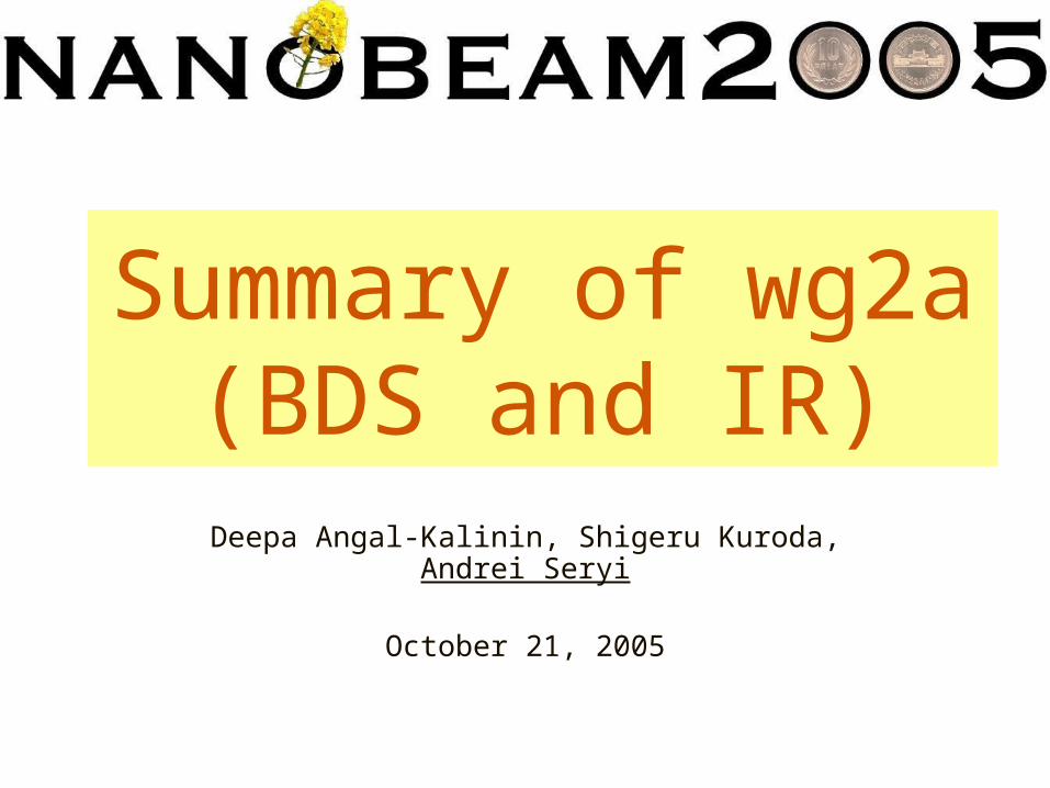
Topics and talks• Since Snowmass, concentrated on configuration with
intermediate crossing angle (14mrad) for single IR, now have the design – Status of extraction 14mrad optics -- Tom Markiewicz– IR optics optimization, FD optics, DID, anti-DID -- Andrei Seryi – BDS civil layouts & upgrade from single IR to two IR -- Andrei Seryi – Design of magnets for 14mrad -- Brett Parker (wg2d)
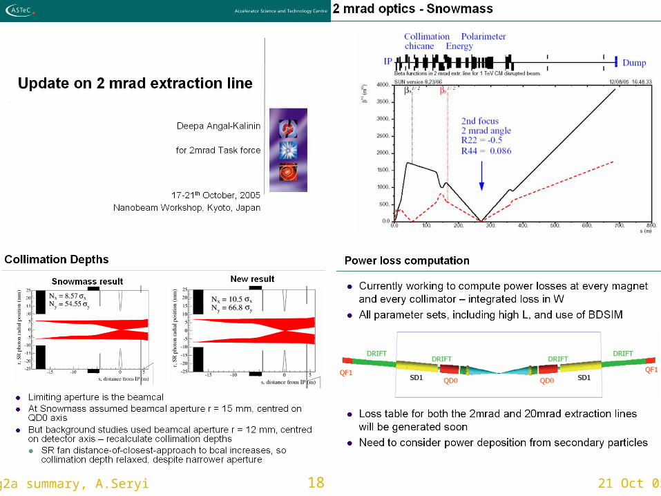
• Continue development of 2mrad design– Update on 2mrad design -- Deepa Angal-Kalinin
• Continue design of various BDS systems– Thoughts on Linear Collider Fast-Abort Systems -- Tom Mattison – Crab cavity status -- Deepa Angal-Kalinin – Diagnostics length, laser wire requirements – D.Angal-Kalinin,
G.Blair
• New developments and critical considerations– Alternative Design for Collimation System -- Angeles Faus-Golfe – IR design issues -- Tom Markiewicz
(wg1)
3 21 Oct 05wg2a summary, A.Seryi
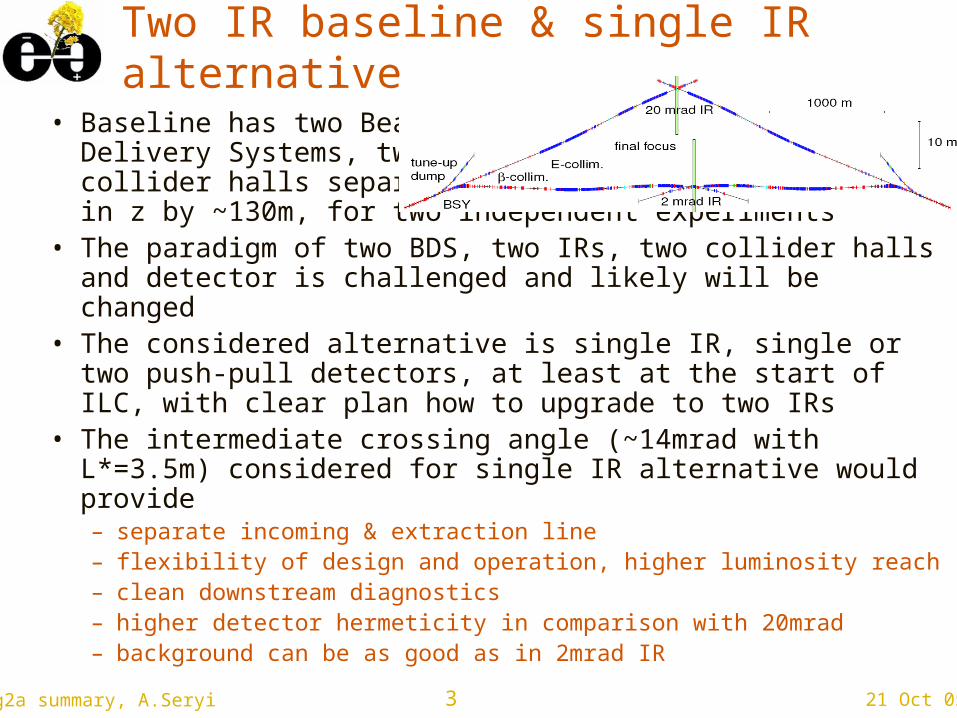
Two IR baseline & single IR alternative
• Baseline has two Beam Delivery Systems, two collider halls separated in z by ~130m, for two independent experiments
• The paradigm of two BDS, two IRs, two collider halls and detector is challenged and likely will be changed
• The considered alternative is single IR, single or two push-pull detectors, at least at the start of ILC, with clear plan how to upgrade to two IRs
• The intermediate crossing angle (~14mrad with L*=3.5m) considered for single IR alternative would provide– separate incoming & extraction line – flexibility of design and operation, higher luminosity reach – clean downstream diagnostics– higher detector hermeticity in comparison with 20mrad– background can be as good as in 2mrad IR
4 21 Oct 05wg2a summary, A.Seryi
5 21 Oct 05wg2a summary, A.Seryi
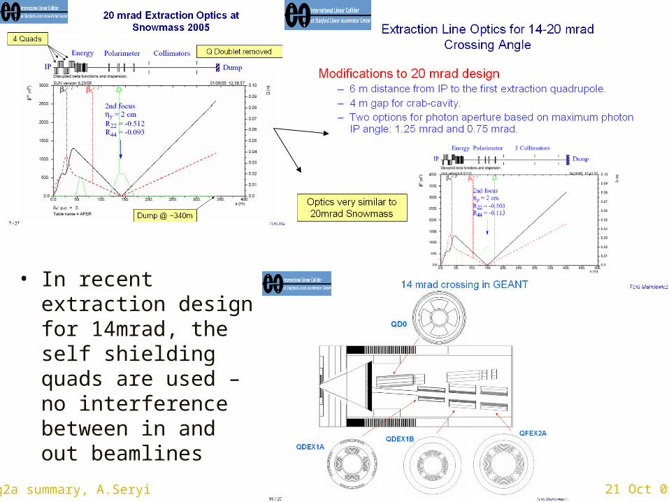
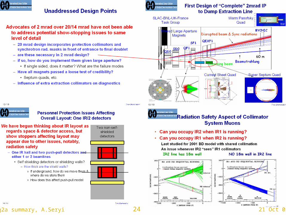
• In recent extraction design for 14mrad, the self shielding quads are used – no interference between in and out beamlines
6 21 Oct 05wg2a summary, A.Seryi
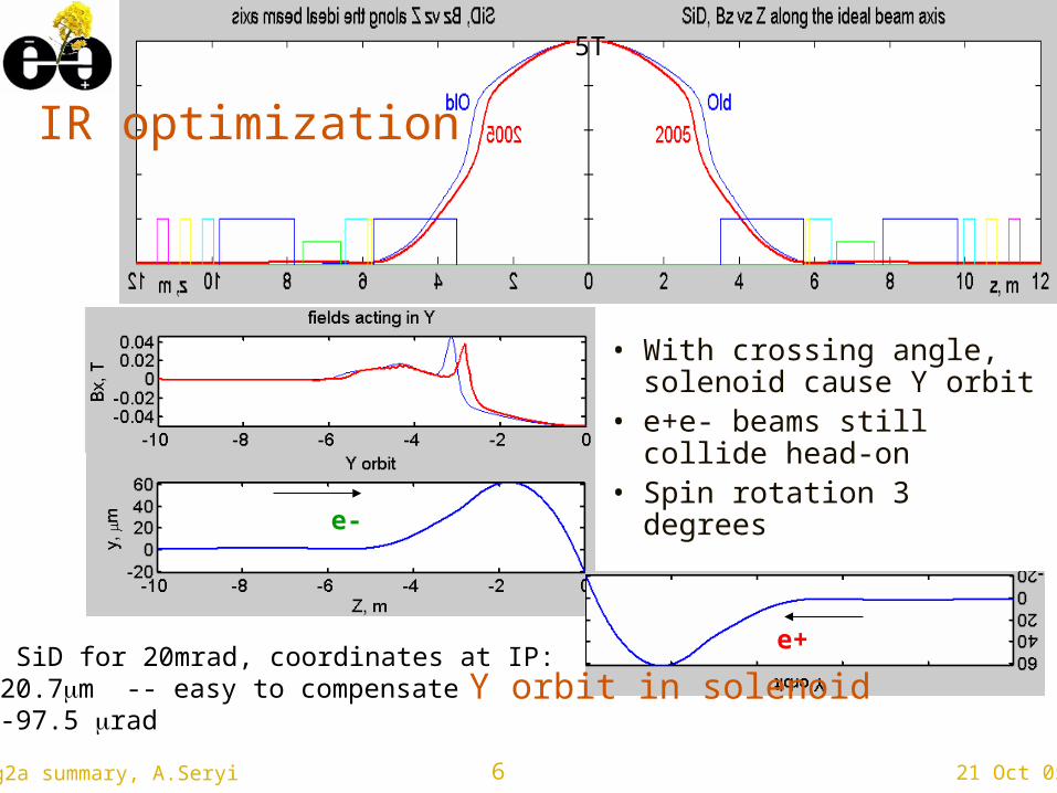
2005 SiD for 20mrad, coordinates at IP:y= -20.7m -- easy to compensate y’= -97.5 rad
• With crossing angle, solenoid cause Y orbit
• e+e- beams still collide head-on
• Spin rotation 3 degrees
5T
IR optimization
e-
e+
Y orbit in solenoid
7 21 Oct 05wg2a summary, A.Seryi
DID field
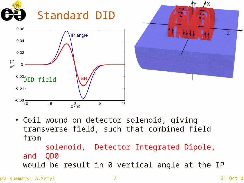
Standard DID
• Coil wound on detector solenoid, giving transverse field, such that combined field from solenoid, Detector Integrated Dipole, and QD0 would be result in 0 vertical angle at the IP
8 21 Oct 05wg2a summary, A.Seryi
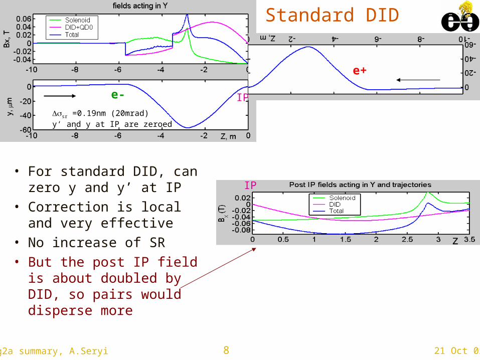
sr =0.19nm (20mrad)y‘ and y at IP are zeroed
Standard DID
• For standard DID, can zero y and y’ at IP
• Correction is local and very effective
• No increase of SR• But the post IP field is
about doubled by DID, so pairs would disperse more
IP
IP
e-
e+
z
9 21 Oct 05wg2a summary, A.Seryi
anti-DID for intermediate crossing angle
• Normal polarity of Detector Integrated Dipole (DID) allows to compensate locally the effect of crossing the solenoid field for the incoming beam, while the field seen by outgoing beam (and low energy pairs) about doubles
• Reversing polarity of Detector Integrated Dipole (anti-DID) could effectively zero the crossing angle for outgoing beam (and pairs) but would increase it (1.5-1.6 times) for incoming beam
• Increasing the effective crossing angle for incoming beam may create too much synchrotron radiation size growth (which depend as SR5/2)
• Smaller initial crossing angle (14mrad) ease the use of anti-DID
10 21 Oct 05wg2a summary, A.Seryi
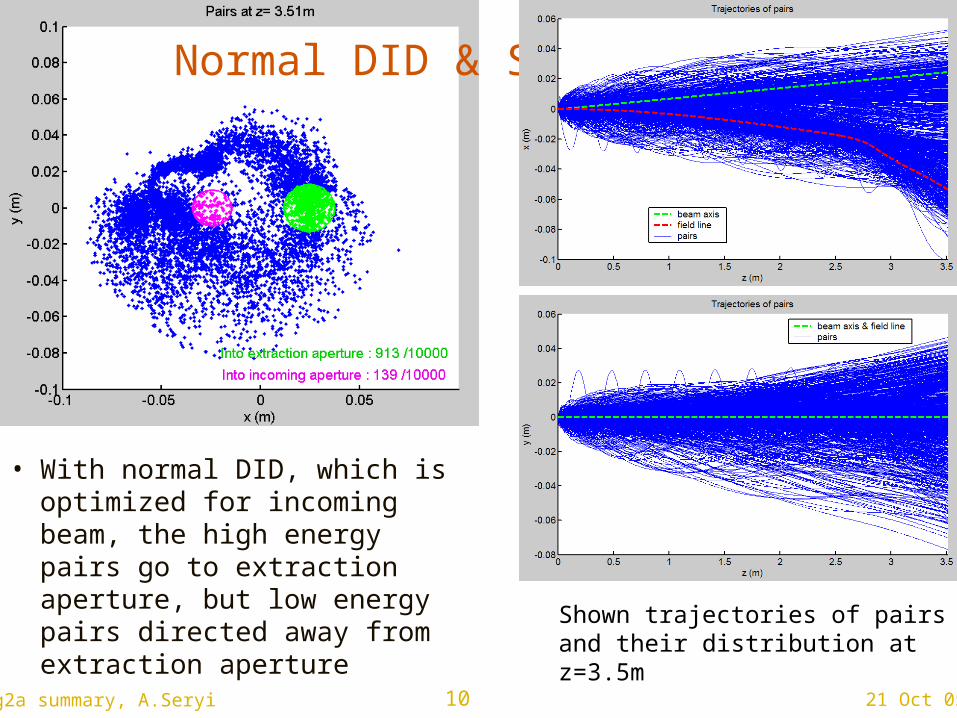
Normal DID & SiD
• With normal DID, which is optimized for incoming beam, the high energy pairs go to extraction aperture, but low energy pairs directed away from extraction aperture
Shown trajectories of pairs and their distribution at z=3.5m
11 21 Oct 05wg2a summary, A.Seryi
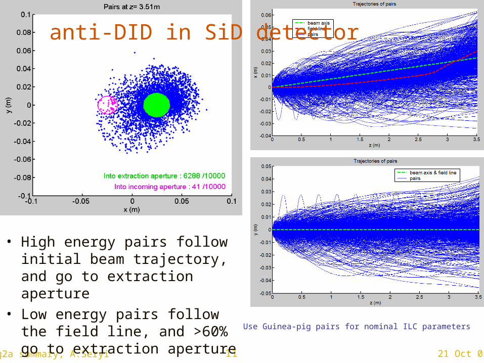
• High energy pairs follow initial beam trajectory, and go to extraction aperture
• Low energy pairs follow the field line, and >60% go to extraction aperture
Use Guinea-pig pairs for nominal ILC parameters
anti-DID in SiD detector
12 21 Oct 05wg2a summary, A.Seryi
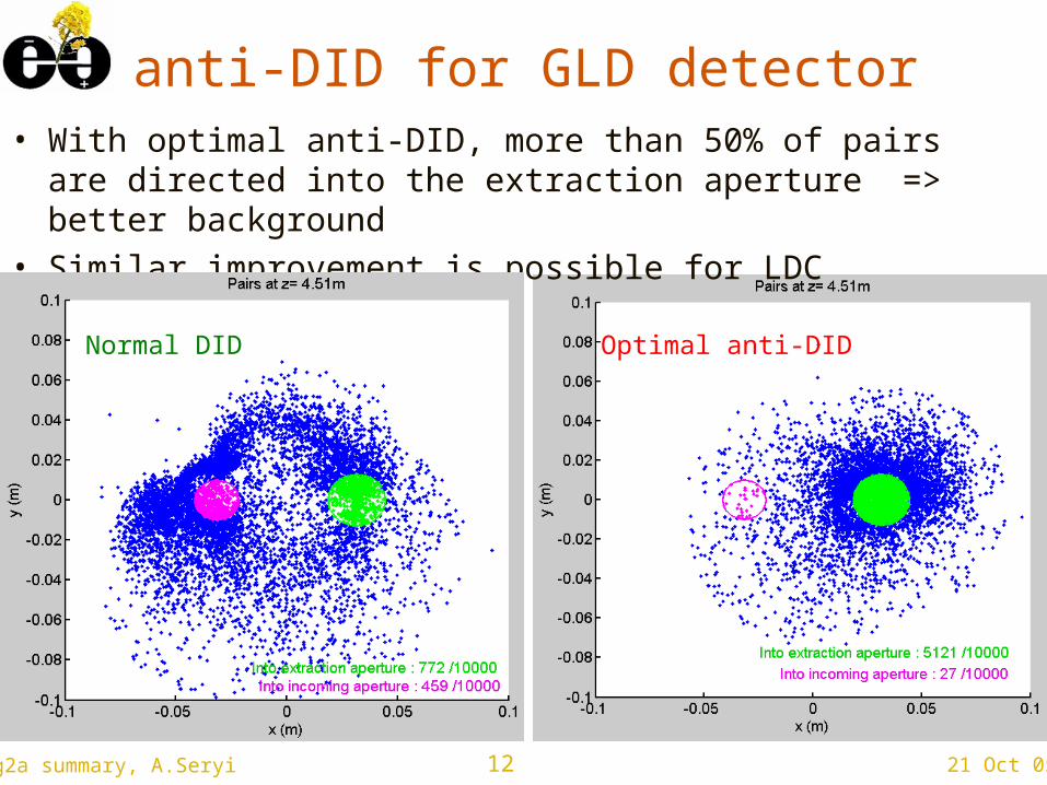
anti-DID for GLD detector• With optimal anti-DID, more than 50% of pairs are
directed into the extraction aperture => better background
• Similar improvement is possible for LDC detector
Optimal anti-DIDNormal DID
13 21 Oct 05wg2a summary, A.Seryi
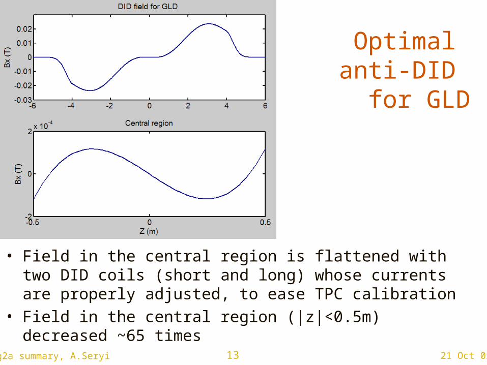
Optimal anti-DID for GLD
• Field in the central region is flattened with two DID coils (short and long) whose currents are properly adjusted, to ease TPC calibration
• Field in the central region (|z|<0.5m) decreased ~65 times
14 21 Oct 05wg2a summary, A.Seryi
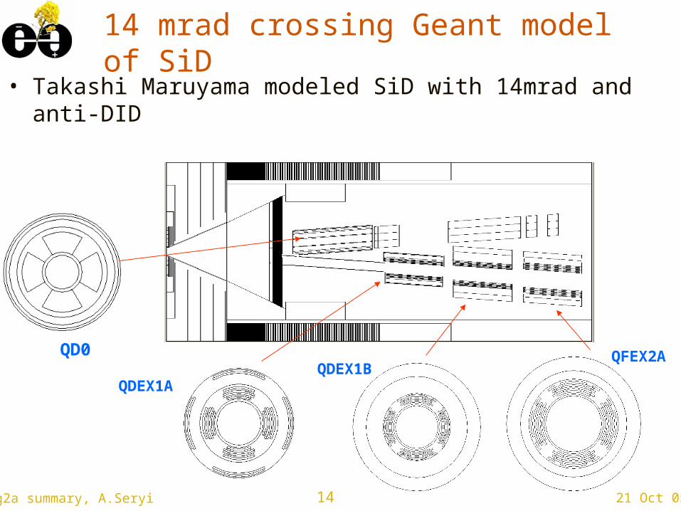
QD0
QDEX1AQDEX1B
QFEX2A
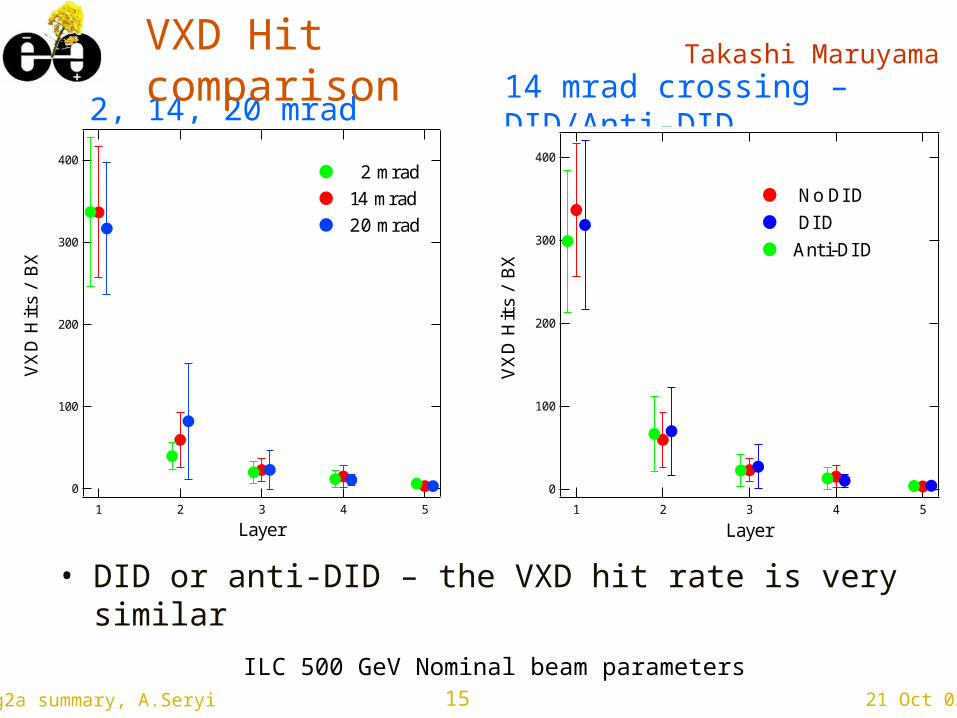
14 mrad crossing Geant model of SiD
• Takashi Maruyama modeled SiD with 14mrad and anti-DID
15 21 Oct 05wg2a summary, A.Seryi
2, 14, 20 mrad400
300
200
100
0
VX
D H
its
/ BX
54321
Layer
2 mrad14 mrad20 mrad
ILC 500 GeV Nominal beam parameters
14 mrad crossing – DID/Anti-DID
400
300
200
100
0
VX
D H
its
/ B
X54321
Layer
No DI D DI DAnti-DI D
VXD Hit comparison
Takashi Maruyama
• DID or anti-DID – the VXD hit rate is very similar
16 21 Oct 05wg2a summary, A.Seryi
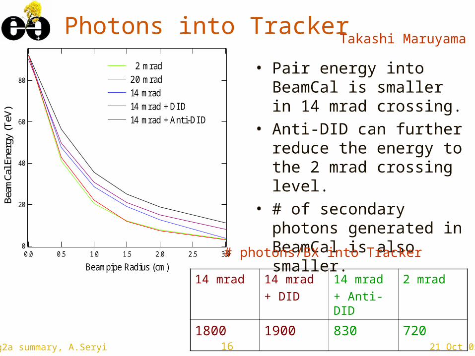
Photons into Tracker
• Pair energy into BeamCal is smaller in 14 mrad crossing.
• Anti-DID can further reduce the energy to the 2 mrad crossing level.
• # of secondary photons generated in BeamCal is also smaller.
80
60
40
20
0
Beam
Cal E
nerg
y (T
eV)
3.02.52.01.51.00.50.0
Beampipe Radius (cm)
2 mrad 20 mrad 14 mrad 14 mrad + DI D 14 mrad + Anti-DI D
# photons/BX into Tracker
14 mrad 14 mrad+ DID
14 mrad+ Anti-DID
2 mrad
1800 1900 830 720
Takashi Maruyama
17 21 Oct 05wg2a summary, A.Seryi
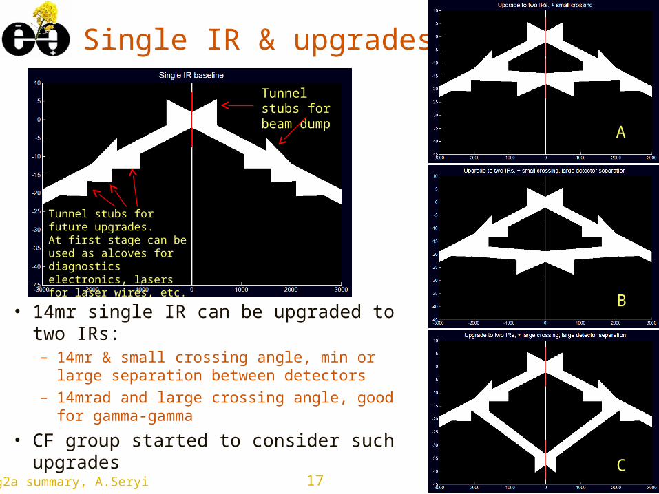
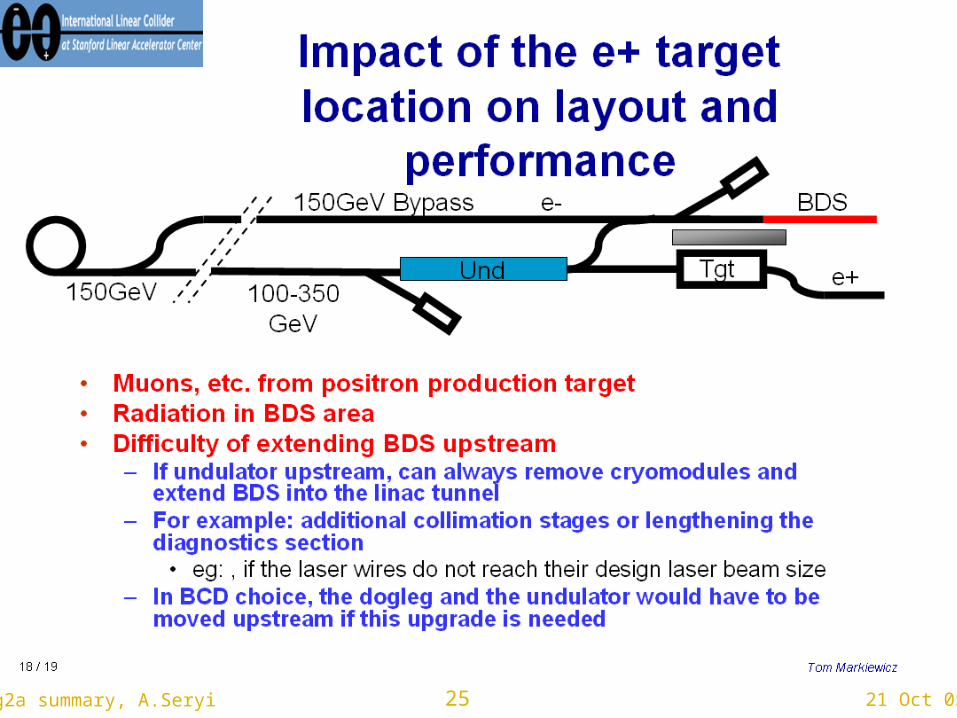
Tunnel stubs for beam dump
Tunnel stubs for future upgrades.At first stage can be used as alcoves for diagnostics electronics, lasers for laser wires, etc.
Single IR & upgrades
• 14mr single IR can be upgraded to two IRs:– 14mr & small crossing angle, min or large
separation between detectors– 14mrad and large crossing angle, good for
gamma-gamma
• CF group started to consider such upgrades
A
B
C
18 21 Oct 05wg2a summary, A.Seryi
19 21 Oct 05wg2a summary, A.Seryi
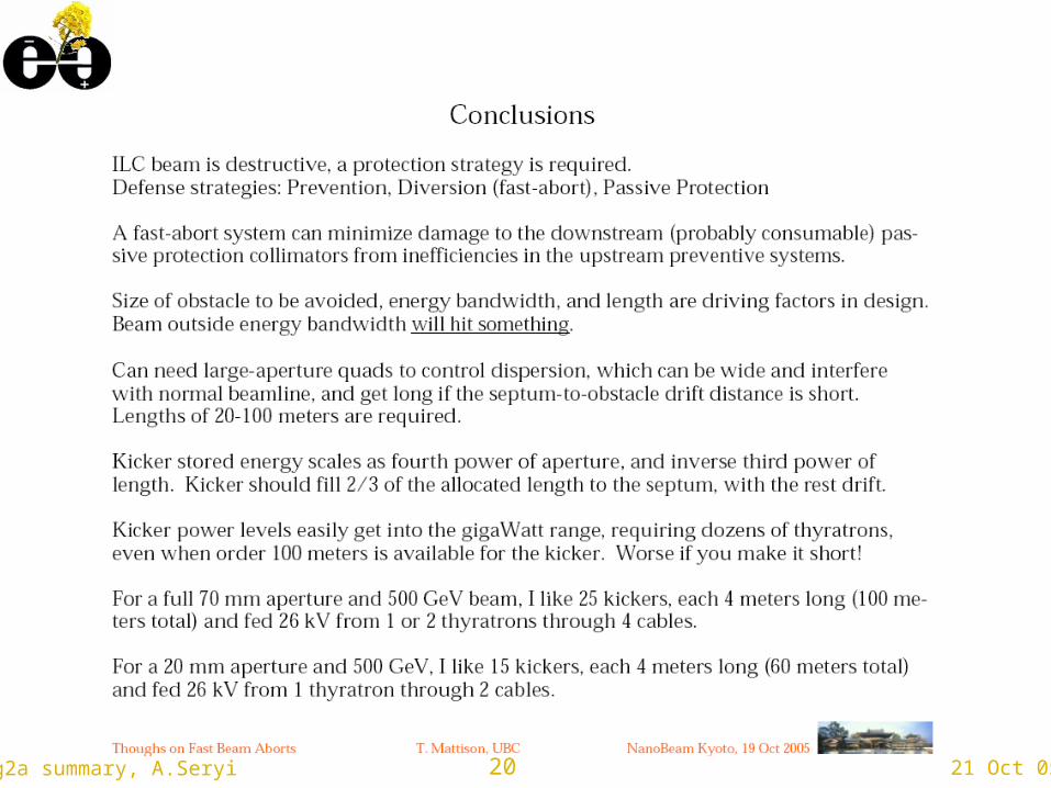
20 21 Oct 05wg2a summary, A.Seryi
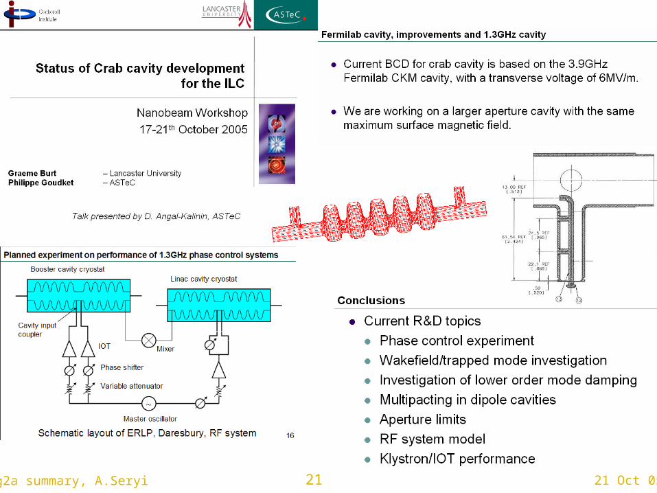
21 21 Oct 05wg2a summary, A.Seryi

22 21 Oct 05wg2a summary, A.Seryi
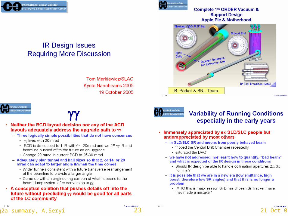
23 21 Oct 05wg2a summary, A.Seryi
24 21 Oct 05wg2a summary, A.Seryi
25 21 Oct 05wg2a summary, A.Seryi
26 21 Oct 05wg2a summary, A.Seryi
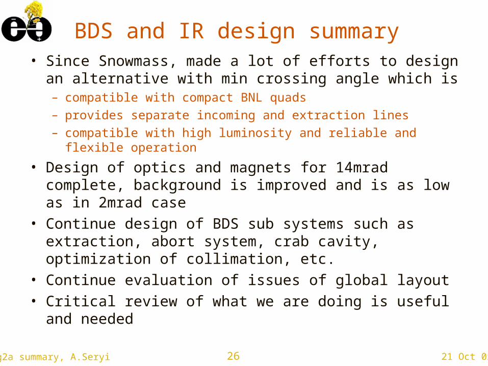
BDS and IR design summary• Since Snowmass, made a lot of efforts to design
an alternative with min crossing angle which is– compatible with compact BNL quads– provides separate incoming and extraction lines– compatible with high luminosity and reliable and flexible
operation
• Design of optics and magnets for 14mrad complete, background is improved and is as low as in 2mrad case
• Continue design of BDS sub systems such as extraction, abort system, crab cavity, optimization of collimation, etc.
• Continue evaluation of issues of global layout • Critical review of what we are doing is useful and
needed