Embed Size (px)
Citation preview

Beam Delivery, MDI related updates
Andrei Seryifor BDS Area
GDE/LCWS meeting at BangaloreMarch 10, 2006

10 Mar 062
Contents• Will review several MDI related issues that were discussed
after Frascati GDE meeting. Use slides from talks given at GDE meetings at KEK in January and Fermilab in February
• Muon walls and detector tolerance to muons• Low E positron transport in BDS• IR layout and radiation physics• Concepts of upgrade to and back to e+e-• Extraction lines & linac orientation• Updates on IR magnet designs• Updates on crab cavity developments• Missing bends and E upgrade

10 Mar 063
Muon walls• BCD: two walls, 9m and 18m per
branch, to reduce muon flux to less than 10muons/200bunches if collimate 0.001 of the beam
• Predictions of halo ~1e-6 - 1e-5• Min one 5m wall needed for PPS• Approach: consider installing single
5m wall, space in tunnel for full set• The 5m wall allow to collimate 2e-5
before reaching 10/200bunches • Before the CCR can be considered
=>– ask Accel. Phys. Tech. System to
evaluate predictions of halo population
– ask Installation Tech. System to evaluate possibility to install additional wall if muon rate will exceed the limit
– ask MDI panel to evaluate the 10/200bunches detector tolerance
No magnetic wall 5 m wall at S = -321m18 m wall at S = -321m
250 GeV beamLew Keller
Muon Momenta from PC-3 Hitting 6.5 m Detector

10 Mar 064
Low energy e+ transport in BDS• Layout (cost) & interference with detector and
BDS are the main questions• Options for e+ transport:
– option 1: separate tunnel ~ 0.7-0.8km long going around larger crossing angle IR
– option 2: going under the IR hall (the e+ beamline is 21 m under the IP beamlines). This is similar to TESLA (where dh was 17m)
– option 3: going from tunnel of 1st IR to tunnel of 2nd IR and back
• Info on e+ beam (tbc)– Energy range considered: 250MeV-1GeV (5GeV also was
discussed)– Power 20kW – 80kW– Energy spread 10% – 2.5%

10 Mar 065
e+ transport, option 1 (around IR)
e+ tunnel
Layouts by Fred Asiri et al.

10 Mar 066
e+ transport, option 2 (under IR hall)
10 Mar 067
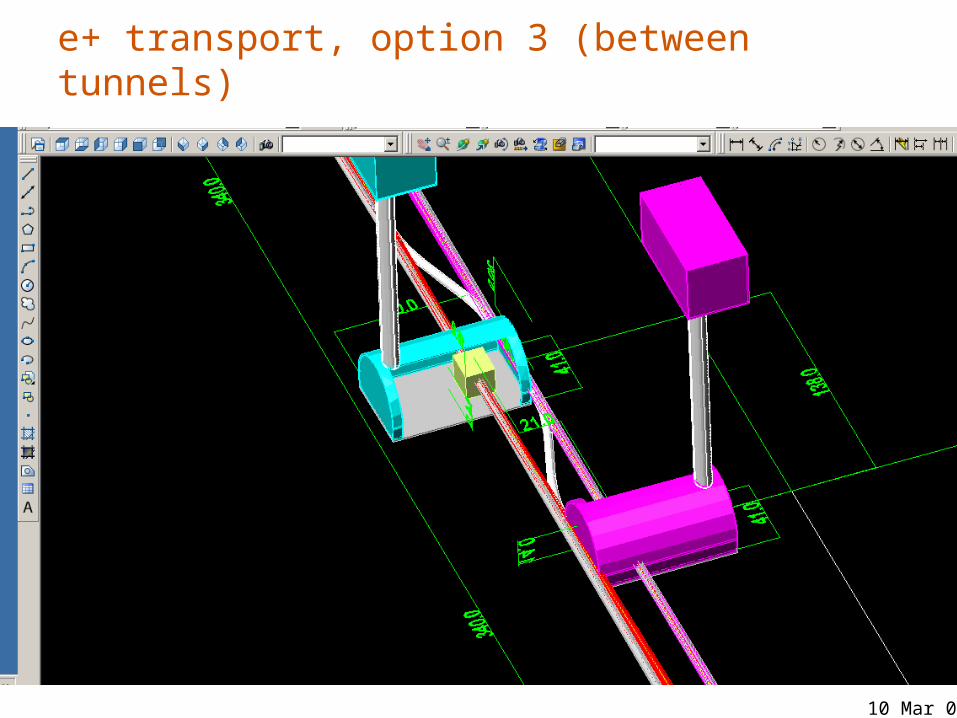
e+ transport, option 3 (between tunnels)

10 Mar 068
A

10 Mar 069
e+ transport
downstream diagn.
downstream diagn.
10 Mar 0610
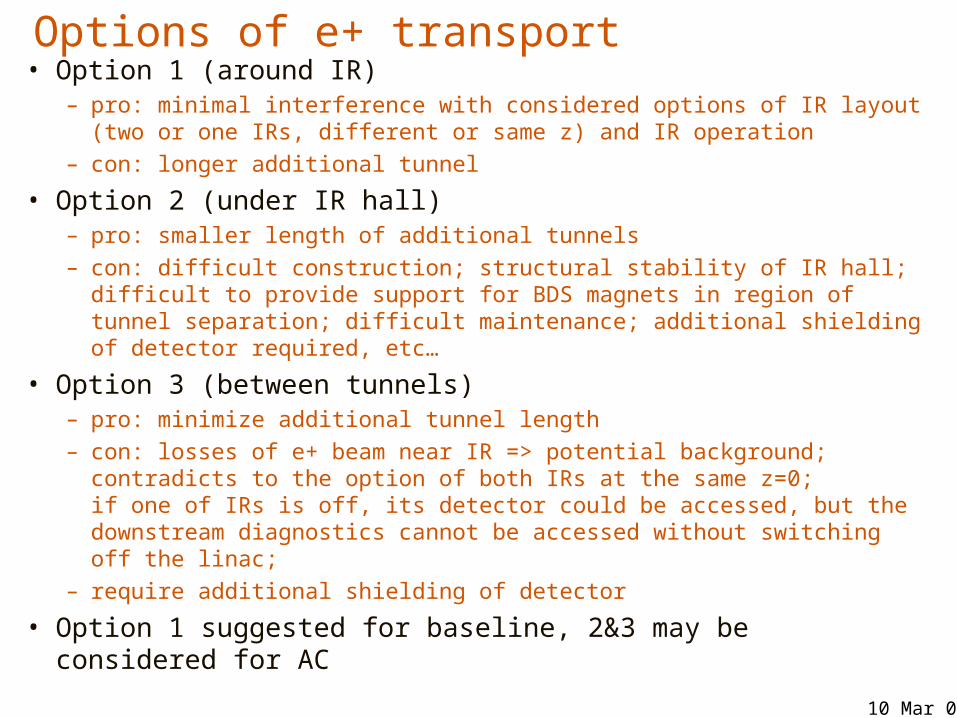
Options of e+ transport• Option 1 (around IR)
– pro: minimal interference with considered options of IR layout (two or one IRs, different or same z) and IR operation
– con: longer additional tunnel
• Option 2 (under IR hall)– pro: smaller length of additional tunnels – con: difficult construction; structural stability of IR hall; difficult to
provide support for BDS magnets in region of tunnel separation; difficult maintenance; additional shielding of detector required, etc…
• Option 3 (between tunnels)– pro: minimize additional tunnel length– con: losses of e+ beam near IR => potential background;
contradicts to the option of both IRs at the same z=0; if one of IRs is off, its detector could be accessed, but the downstream diagnostics cannot be accessed without switching off the linac;
– require additional shielding of detector
• Option 1 suggested for baseline, 2&3 may be considered for AC

10 Mar 0611
Separate & single hall options, Rad. phys. and PPS• Questions to study: wall thickness and
location, packman thickness, tunnel to hall transition, etc
Wall
“Pacman”
Fenceoptional

10 Mar 0612
IR design and Radiation safety design criteria• IR design requires the radiation safety criteria to be
defined• Started the work on “ILC radiation guidance
document”– beam containment policies and devices, conditions for
occupancy
• For IR region, in particular, defines – Normal operation: dose less than 0.05 mrem/hr
(integrated less than 0.1 rem in a year with 2000 hr/year) – Accidents: dose less than 25rem/hr and integrated less
than 0.1 rem for 36MW of maximum credible incident (MCI)
• The team presently includes N.Mokhov, D.Cossairt, L.Keller, S.Rokni, A.Fasso and will be augmented with colleagues from all regions

10 Mar 0613
Hall with shielding wall
• For 36MW MCI, the concrete wall at 10m from beamline should be ~3.1m
Wall
18MW loss on Cu target 9r.l \at s=-8m. No Pacman, no detector. Concrete wall at 10m.Dose rate in mrem/hr.
25 rem/hr
10m
Alberto Fasso et al
10 Mar 0614
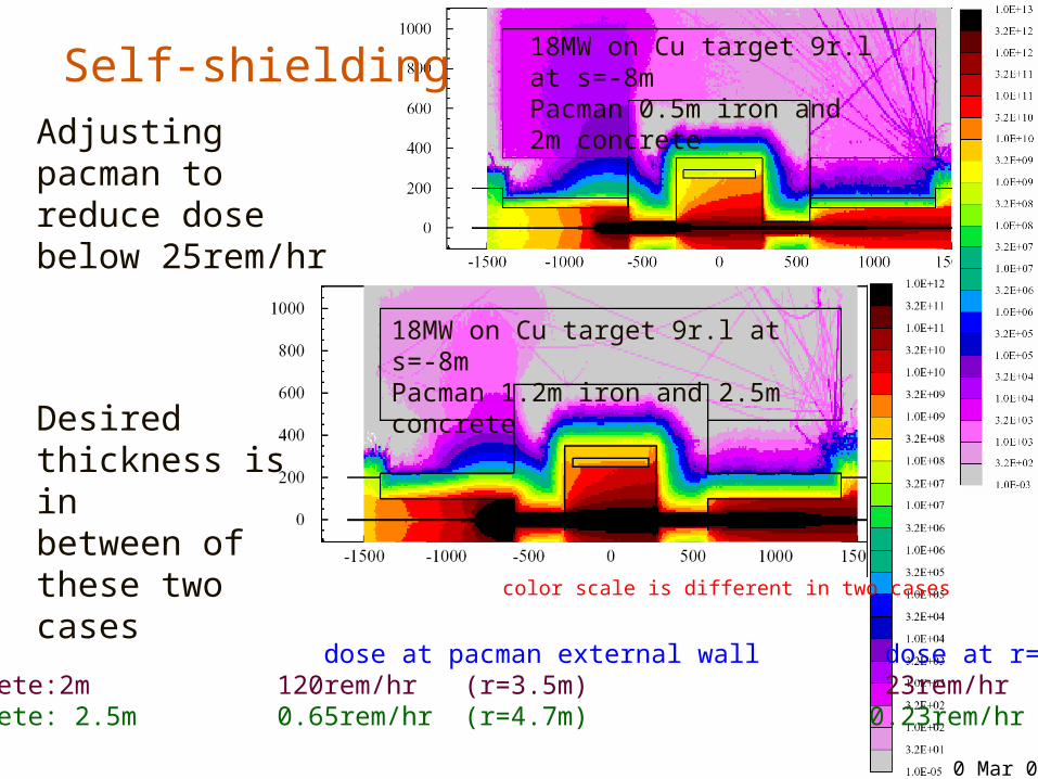
Self-shielding
color scale is different in two cases
18MW on Cu target 9r.l at s=-8mPacman 0.5m iron and 2m concrete
18MW on Cu target 9r.l at s=-8mPacman 1.2m iron and 2.5m concrete
18MW at s=-8m:Packman dose at pacman external wall dose at r=7m Fe: 0.5m, Concrete:2m 120rem/hr (r=3.5m) 23rem/hrFe: 1.2m, Concrete: 2.5m 0.65rem/hr (r=4.7m) 0.23rem/hr
Adjusting pacman to reduce dose below 25rem/hr
Desired thickness is in between ofthese two cases

10 Mar 0615
Self-shieldingImproving tunnel-to-pacman transition, add iron in tunnel and model non-axial symmetrical case
In next iteration will add iron in the marked corners and expect dose to reduce below 25rem/hr
Proper “tunnel plug” can be designed
0.7m of Fe for last 5m of tunnel
Iron
color scale is different in two cases
10 Mar 0616
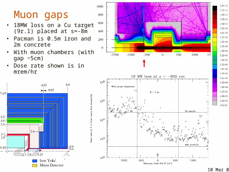
Muon gaps• 18MW loss on a Cu target
(9r.l) placed at s=-8m• Pacman is 0.5m iron and
2m concrete• With muon chambers
(with gap ~5cm) • Dose rate shown is in
mrem/hr

10 Mar 0617
Preliminary conclusions from all cases
• Self-shielding detectors– issue of gaps (muon chambers) need to be solved – entrance of tunnel should be covered by iron as well– distance helps (fencing out the working detector)– if issue of gaps can be solved, ~3m pacman is needed to
meet 25rem/hr MCI requirement – accurate model of detector is very important – studies will continue
• Non self shielding detector– concrete wall at 10m from beamline should be ~3.1m

10 Mar 0618
Upgrade from e+e- to and back to e+e-• Assume that 25mrad is needed for to attain its
max potential • Reversibility of upgrade may be essential
– e.g. e+e- run => run => E upgrade and next e+e- run
• Consider concept for 20mrad or 14mrad IR upgrade

10 Mar 0619
Baseline layout 20mrad IR and 2mrad IR
• Grid size: 100m * 5m• (Beamline is not placed near external walls, as
suggested above)

10 Mar 0620
20mr IR

10 Mar 0621• See notes on next page
20mr => 25mr

10 Mar 0622
Upgrade of 20mr to 25mr and back• Install bend after energy collimator of modify E-coll
bend to create additional 2.5mrad – Will need to study if this affects collimation efficiency and
whether this is an issue for • Pink area show tunnels that need to be built for in
the upgrade or from start• Detector and IP moved by about 1.8m, FF elements
moved• Build new ~0.25km gas dump followed by water
dump for (next slide) in a new tunnel, do not dismantle either the water dump for e+e- or extraction line
• If the beam dump and new tunnel need to be much longer, the positron transfer tunnel should go above the projected path of dump
• In back conversion to e+e-, move FF beamline and detector back, continue to use e+e- water dump.

10 Mar 0623
Assumed this dump for (feasibility to be studied)

10 Mar 0624
14mr => 25mr
• additional angle is 5.5mrad and detector need to move by about 4.2m
10 Mar 0625
Upgrade of 14mr to 25mr and back• Additional comments• Tunnel in FF area may need to be wider• The gg dump is in separate tunnel – may ease
radiation issues and upgrade back to e+e-

10 Mar 0626
Extraction line and linac angles• Extraction line study
– Detailed studies of extraction lines is ongoing. – Synchrotron radiation of disrupted beam in chicanes
reach 0.76MW for 1TeV CM in 2mrad beamline. Protection collimators with up to 1TGy/yr peak dose which can severely limit the lifetime even for metals (N.Mokhov, A.Drozhdin et al)
• Linac angles are fixed to 20mrad after discussion at KEK GDE Areas meeting in January and following CCR (Configuration Change Request) by the Executive Committee

10 Mar 0627
QD0SD0 QF1
SF1 Q,S,QEXF1
Disrupted beam & Sync radiations
BeamstrahlungIncoming beam
60 m
Shared Large Aperture Magnets
Rutherford cable SC quad and sextupole
pocket coil quad
2mrad IR: Fermi and possibly Saclay will look on feasibility and cost estimates

10 Mar 0628
Progress on 14mrad solution, BNL• Brief summary from Brett Parker:• Working on support structure, cryostat design, verified
space for He-II cooling, will start modeling temperature distribution with E deposition calculations
• Close to winding a short sectupole (SD0 prototype) on top of the OC0 coil we have already wound.
• Integrated both DC and pulsed (1ms) heating elements into the coil to directly measure how much energy deposition (mJ/gm) is needed to cause a quench.
• Will measure the magnetic centers for the octupole and sextupole windings
Final QT assembly with the active shield coil in place
cancellation of the external field with a shield coil has been successfully demonstrated at BNL at the end of 2005

10 Mar 0629
14(20)mrad, BNL

Model of 3.9GHz deflecting (crab) cavity designed by Fermilab
Collaboration is being formed to work on ILC crab cavity systems: Fermilab, Daresbury, SLAC, …
The 3.9GHz deflecting cavity designed at Fermilab. Several simplified models have been manufactured. Complete design with all couplers exist now. Design is being verified with various tools including parallel codes (see next page), and then a prototype will be built. The phase stabilization system is being designed.

Parallel Electromagnetic Codes - SLAC
Parallel codes capable of simulating complex 3D cavities in time and frequency domains were applied to the optimization of HOM damping in ILC Low-Loss cavity. The plan is to apply the same capabilities to the design of the 3.9 GHz crab cavity.
ILC Low-Loss Cavity
1.0E+01
1.0E+02
1.0E+03
1.0E+04
1.0E+05
1.0E+06
1.0E+07
1.50 2.00 2.50 3.00F (GHz)
Qex
t
HOM Damping (Omega3P)
Wakefields (T3P)

10 Mar 0632
• At 500GeV CM will install 50% or even less number of bends to cut the cost. These bends need to be installed after the energy upgrade.
• Bends will be split and arranged in strings so that decreasing the energy much below the nominal 500GeV CM will be done by switching off the strings.
Example shows one of possible configuration in the FF part (Y.Nosochkov)
Missing bend strategy at 500GeV CM
10 Mar 0633
Summary• We discussed updates on several MDI related
design issues
• Important issues to be focused on:– Taking into account real life constraints, – how to build a consensus toward two or one IRs?– … two or one detector?– … push-pull or normal?– … how to ensure that community support is not
decreased if the number of IRs and detectors goes to minimum?