Embed Size (px)
Citation preview


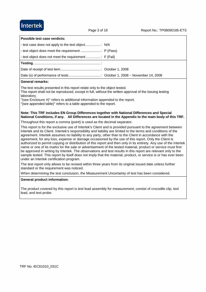
Page 2 of 18 Report No.: TP08090185-ETS
TRF No. IEC61010_031C
Summary of testing:
Tests performed (name of test and test clause):
5.3 Durability of Markings Test 6.3.1 Voltage, Current, and Capacitance Test
6.6 Voltage Test
6.7.4.1 Pull Test
6.7.4.2 Flexing/Pull Test
6.7.4.3 Rotational Flexing Test
6.7.5 Insulation of a Probe Cable 8.1 Rigidity Test
8.2 Drop Test
8.3 Impact Swing Test
9.2 Temperature Test
10.1 Maximum Ambient Temperature Test
10.2 a) Non-Metallic Enclosure Test (Non-operative treatment)
10.2 b) Non-Metallic Enclosure Test (Operative treatment)
11.2 Cleaning Test
Summary of compliance with National Differences: N/ A
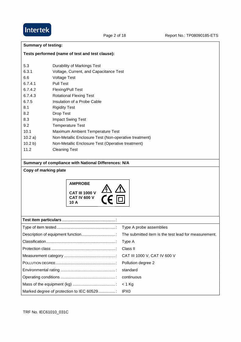
Copy of marking plate
Test item particulars ..................................................:
Type of item tested .......................................................: Type A probe assemblies
Description of equipment function................................: The submitted item is the test lead for measurement.
Classification.................................................................: Type A
Protection class ............................................................: Class II
Measurement category ................................................: CAT III 1000 V, CAT IV 600 V
POLLUTION DEGREE........................................................: Pollution degree 2
Environmental rating ................................................. : standard
Operating conditions ................................................. : continuous
Mass of the equipment (kg) ...................................... : < 1 Kg
Marked degree of protection to IEC 60529............... : IPX0
AMPROBE CAT III 1000 V CAT IV 600 V 10 A
Page 3 of 18 Report No.: TP08090185-ETS
TRF No. IEC61010_031C
Possible test case verdicts:
- test case does not apply to the test object................. : N/A
- test object does meet the requirement ...................... : P (Pass)
- test object does not meet the requirement ................ : F (Fail)
Testing .......................................................................... :
Date of receipt of test item............................................ : October 1, 2008
Date (s) of performance of tests................................... : October 1, 2008 ~ November 14, 2008
General remarks:
The test results presented in this report relate only to the object tested. This report shall not be reproduced, except in full, without the written approval of the Issuing testing laboratory. "(see Enclosure #)" refers to additional information appended to the report. "(see appended table)" refers to a table appended to the report.
Note: This TRF includes EN Group Differences togeth er with National Differences and Special National Conditions, if any. All Differences are l ocated in the Appendix to the main body of this TRF .
Throughout this report a comma (point) is used as the decimal separator.
This report is for the exclusive use of Intertek's Client and is provided pursuant to the agreement between Intertek and its Client. Intertek's responsibility and liability are limited to the terms and conditions of the agreement. Intertek assumes no liability to any party, other than to the Client in accordance with the agreement, for any loss, expense or damage occasioned by the use of this report. Only the Client is authorized to permit copying or distribution of this report and then only in its entirety. Any use of the Intertek name or one of its marks for the sale or advertisement of the tested material, product or service must first be approved in writing by Intertek. The observations and test results in this report are relevant only to the sample tested. This report by itself does not imply that the material, product, or service is or has ever been under an Intertek certification program.
The test report only allows to be revised within three years from its original issued date unless further standard or the requirement was noticed.
When determining the test conclusion, the Measurement Uncertainty of test has been considered.
General product information:
The product covered by this report is test lead assembly for measurement; consist of crocodile clip, test lead, and test probe.
Page 4 of 18 Report No. TP08090185-ETS:
IEC 61010-031
Clause Requirement + Test Result - Remark Verdict
TRF No. IEC61010_031C
5 MARKING AND DOCUMENTATION P
5.1 Markings Info
5.1.1 Markings applicable for whole probe assembly not located on operator removable parts
Mark on the surface of hand-held part
P
Letter symbols (IEC 60027) used P
Graphic symbols (Table 1) used; or P
if other symbol used; explained in accompanying documentation
P
In case of less space for required markings: All markings are provided on the product
P
- symbol 10 of table 1 used P
- all necessary information included in documentation
P
5.1.2 Identification Info
5.1.2 a) Name or registered trademark AMPROBE P
5.1.2 b) For type B and C, also model no. or similar Type A probe N/A
If designed for use with specific model this is made clear and
Not use with specific model N/A
model identified by marking or in documentation N/A
5.1.3 Fuses Not provided with any fuse N/A
All details necessary for fuse replacement N/A
Includes rated voltage and current breaking capacity
N/A
If selected according to particular application; marked with symbol 10 and information in documentation
N/A
5.1.4 Necessary identification for TERMINALS, connectors etc
N/A
5.1.6 Rating Info
Maximum RATED voltage to earth P
(CAT I) Symbol 10 used Not only for CAT I N/A
(CAT II-IV) Category marked CAT III P
Nature of voltage (ac, dc etc.) 1000 Vac P
Reference connector intended for connection to voltages exceeding the values of 6.3.1.1
N/A
Page 5 of 18 Report No. TP08090185-ETS:
IEC 61010-031
Clause Requirement + Test Result - Remark Verdict
TRF No. IEC61010_031C
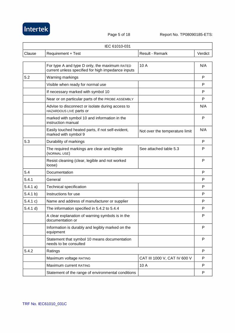
For type A and type D only, the maximum RATED current unless specified for high impedance inputs
10 A N/A
5.2 Warning markings P
Visible when ready for normal use P
If necessary marked with symbol 10 P
Near or on particular parts of the PROBE ASSEMBLY P
Advise to disconnect or isolate during access to HAZARDOUS LIVE parts or
N/A
marked with symbol 10 and information in the instruction manual
P
Easily touched heated parts, if not self-evident, marked with symbol 9
Not over the temperature limit N/A
5.3 Durability of markings P
The required markings are clear and legible (NORMAL USE)
See attached table 5.3 P
Resist cleaning (clear, legible and not worked loose)
P
5.4 Documentation P
5.4.1 General P
5.4.1 a) Technical specification P
5.4.1 b) Instructions for use P
5.4.1 c) Name and address of manufacturer or supplier P
5.4.1 d) The information specified in 5.4.2 to 5.4.4 P
A clear explanation of warning symbols is in the documentation or
P
Information is durably and legibly marked on the equipment
P
Statement that symbol 10 means documentation needs to be consulted
P
5.4.2 Ratings P
Maximum voltage RATING CAT III 1000 V, CAT IV 600 V P
Maximum current RATING 10 A P
Statement of the range of environmental conditions P
Page 6 of 18 Report No. TP08090185-ETS:
IEC 61010-031
Clause Requirement + Test Result - Remark Verdict
TRF No. IEC61010_031C
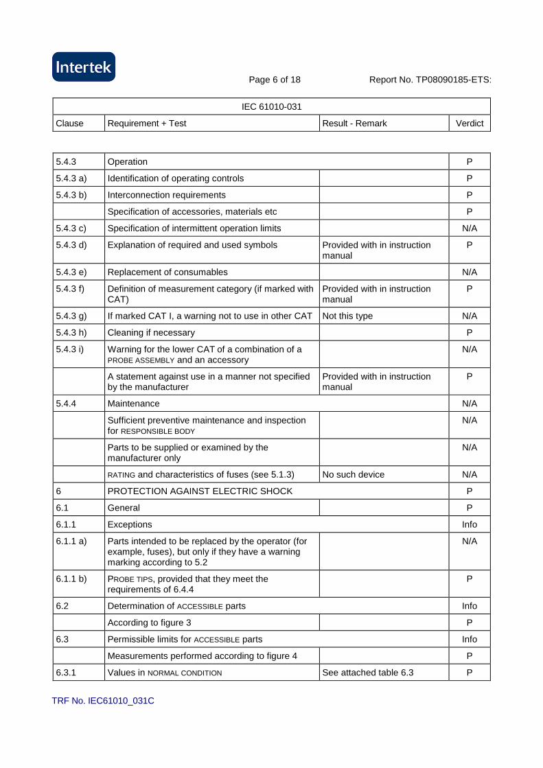
5.4.3 Operation P
5.4.3 a) Identification of operating controls P
5.4.3 b) Interconnection requirements P
Specification of accessories, materials etc P
5.4.3 c) Specification of intermittent operation limits N/A
5.4.3 d) Explanation of required and used symbols Provided with in instruction manual
P
5.4.3 e) Replacement of consumables N/A
5.4.3 f) Definition of measurement category (if marked with CAT)
Provided with in instruction manual
P
5.4.3 g) If marked CAT I, a warning not to use in other CAT Not this type N/A
5.4.3 h) Cleaning if necessary P
5.4.3 i) Warning for the lower CAT of a combination of a PROBE ASSEMBLY and an accessory
N/A
A statement against use in a manner not specified by the manufacturer
Provided with in instruction manual
P
5.4.4 Maintenance N/A
Sufficient preventive maintenance and inspection for RESPONSIBLE BODY
N/A
Parts to be supplied or examined by the manufacturer only
N/A
RATING and characteristics of fuses (see 5.1.3) No such device N/A
6 PROTECTION AGAINST ELECTRIC SHOCK P
6.1 General P
6.1.1 Exceptions Info
6.1.1 a) Parts intended to be replaced by the operator (for example, fuses), but only if they have a warning marking according to 5.2
N/A
6.1.1 b) PROBE TIPS, provided that they meet the requirements of 6.4.4
P
6.2 Determination of ACCESSIBLE parts Info
According to figure 3 P
6.3 Permissible limits for ACCESSIBLE parts Info
Measurements performed according to figure 4 P
6.3.1 Values in NORMAL CONDITION See attached table 6.3 P
Page 7 of 18 Report No. TP08090185-ETS:
IEC 61010-031
Clause Requirement + Test Result - Remark Verdict
TRF No. IEC61010_031C
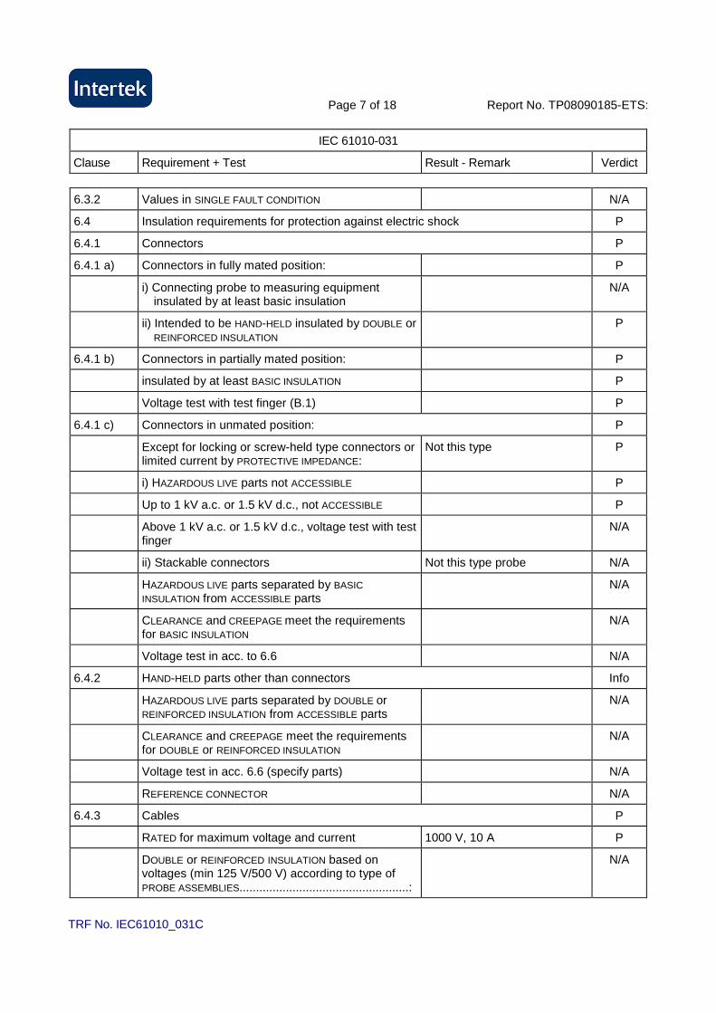
6.3.2 Values in SINGLE FAULT CONDITION N/A
6.4 Insulation requirements for protection against electric shock P
6.4.1 Connectors P
6.4.1 a) Connectors in fully mated position: P
i) Connecting probe to measuring equipment insulated by at least basic insulation
N/A
ii) Intended to be HAND-HELD insulated by DOUBLE or REINFORCED INSULATION
P
6.4.1 b) Connectors in partially mated position: P
insulated by at least BASIC INSULATION P
Voltage test with test finger (B.1) P
6.4.1 c) Connectors in unmated position: P
Except for locking or screw-held type connectors or limited current by PROTECTIVE IMPEDANCE:
Not this type P
i) HAZARDOUS LIVE parts not ACCESSIBLE P
Up to 1 kV a.c. or 1.5 kV d.c., not ACCESSIBLE P
Above 1 kV a.c. or 1.5 kV d.c., voltage test with test finger
N/A
ii) Stackable connectors Not this type probe N/A
HAZARDOUS LIVE parts separated by BASIC INSULATION from ACCESSIBLE parts
N/A
CLEARANCE and CREEPAGE meet the requirements for BASIC INSULATION
N/A
Voltage test in acc. to 6.6 N/A
6.4.2 HAND-HELD parts other than connectors Info
HAZARDOUS LIVE parts separated by DOUBLE or REINFORCED INSULATION from ACCESSIBLE parts
N/A
CLEARANCE and CREEPAGE meet the requirements for DOUBLE or REINFORCED INSULATION
N/A
Voltage test in acc. 6.6 (specify parts) N/A
REFERENCE CONNECTOR N/A
6.4.3 Cables P
RATED for maximum voltage and current 1000 V, 10 A P
DOUBLE or REINFORCED INSULATION based on voltages (min 125 V/500 V) according to type of PROBE ASSEMBLIES...................................................:
N/A
Page 8 of 18 Report No. TP08090185-ETS:
IEC 61010-031
Clause Requirement + Test Result - Remark Verdict
TRF No. IEC61010_031C
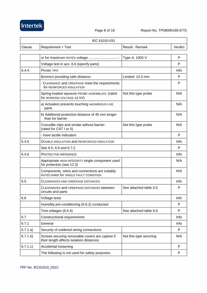
or for maximum RATED voltage ...............................: Type A, 1000 V P
Voltage test in acc. 6.6 (specify parts) P
6.4.4 PROBE TIPS Info
BARRIER providing safe distance: Limited: 14.3 mm P
- CLEARANCE and CREEPAGE meet the requirements for REINFORCED INSULATION
P
Spring-loaded squeeze PROBE ASSEMBLIES: (rated for WORKING VOLTAGE ≤1 kV)
Not this type probe N/A
a) Actuation prevents touching HAZARDOUS LIVE parts
N/A
b) Additional protective distance of 45 mm longer than for barrier
N/A
Crocodile clips and similar without barrier: (rated for CAT I or II)
Not this type probe N/A
- have tactile indication P
6.4.5 DOUBLE INSULATION and REINFORCED INSULATION Info
See 6.5, 6.6 and 6.7.2 P
6.4.6 PROTECTIVE IMPEDANCE Info
Appropriate HIGH-INTEGRITY single component used for protection (see 12.3)
N/A
Components, wires and connections are suitably RATED even for SINGLE FAULT CONDITION
N/A
6.5 CLEARANCES AND CREEPAGE DISTANCES Info
CLEARANCES and CREEPAGE DISTANCES between circuits and parts
See attached table 6.5 P
6.6 Voltage tests Info
Humidity pre-conditioning (6.6.2) conducted P
Test voltages (6.6.4) See attached table 6.6 P
6.7 Constructional requirements Info
6.7.1 General Info
6.7.1 a) Security of soldered wiring connections P
6.7.1 b) Screws securing removable covers are captive if their length affects isolation distances
Not this type securing N/A
6.7.1 c) Accidental loosening P
The following is not used for safety purposes: P

Page 9 of 18 Report No. TP08090185-ETS:
IEC 61010-031
Clause Requirement + Test Result - Remark Verdict
TRF No. IEC61010_031C
1) Materials which can be easily damaged (enamel etc)
P
2) Non-impregnated hygroscopic materials P
6.7.2 ENCLOSURES of PROBE ASSEMBLIES with DOUBLE or REINFORCED INSULATION Info
ENCLOSURE which surrounds all metal parts P
Small metal parts are separated from HAZARDOUS LIVE voltages by DOUBLE or REINFORCED INSULATION
Not provided with small metal part
N/A
ENCLOSURES or parts made of insulating material fulfil requirements for DOUBLE or REINFORCED INSULATION.
P
Protection for metal ENCLOSURES or parts is provided by one of the following:
Plastic Enclosure is provided N/A
a) provision of an insulating coating or BARRIER on the inside of the ENCLOSURE
N/A
b) CLEARANCES and CREEPAGE DISTANCES cannot be reduced by loosening of parts or wires
N/A
6.7.3 Corona and partial discharge P
No corona or partial discharge while operating at maximum voltage
P
6.7.4 Cable attachment P
Withstand forces likely to be encountered P
6.7.4.1 Pull test See attached table 6.7.4.1 P
6.7.4.2 Flexing/pull test See attached table 6.7.4.2 P
6.7.4.3 Rotational flexing test See attached table 6.7.4.3 P
6.7.5 Insulation of a probe cable P
Probe cable with a wear indicator provide DOUBLE or REINFORCED INSULATION when new, and at least BASIC INSULATION when the wear indicator is reached
P
PROBE CABLE without a wear indicator provide DOUBLE or REINFORCED INSULATION
N/A
Voltage test in acc. 6.6 (specify parts): P
- REINFORCED INSULATION: one unconditioned sample before cycling treatment
9648 Vdc P
- BASIC INSULATION: contrasting colour became visible during the cycling treatment
6030 Vdc P
- REINFORCED INSULATION: 250 cycles treatment without contrasting colour becoming visible.
N/A

Page 10 of 18 Report No. TP08090185-ETS:
IEC 61010-031
Clause Requirement + Test Result - Remark Verdict
TRF No. IEC61010_031C
7 PROTECTION AGAINST MECHANICAL HAZARDS P
Handling during normal use shall not lead to hazard P
8 MECHANICAL RESISTANCE TO SHOCK AND IMPACT P
Withstand shock and impact likely to occur in NORMAL USE
P
8.1 Rigidity test Info
20 N applied three times P
8.2 Drop test Info
Three samples dropped P
8.3 Impact swing test Info
Probe subjected to impact against a hardwood board
P
After the tests of 8.1 to 8.3: P
Voltage tests in acc. to 6.6 P
Inspections: P
8a) HAZARDOUS LIVE parts not accessible P
8b) ENCLOSURE shows no cracks (hazard) P
8c) CLEARANCES not less than their permitted values P
8d) BARRIERS not damaged or loosened P
8e) No damage which could cause spread of fire P
9 TEMPERATURE LIMITS AND PROTECTION AGAINST THE SPREAD OF FIRE P
9.1 General Info
Any heating does not cause a HAZARD in NORMAL CONDITION nor in SINGLE FAULT CONDITION
P
No spread of fire outside the PROBE ASSEMBLY P
Easily touched surfaces not exceeding the following limits in NORMAL CONDITION :
P
- metal less than 55 °C N/A
- non-metallic less than 70 °C P
- wires and cables less than 75 °C P
Temperatures in SINGLE FAULT CONDITION less than 105 °C
P
Easily touched heated surfaces recognizable or marked with symbol 9 of table 1 (s. 5.2), if necessary for functional reasons
N/A

Page 11 of 18 Report No. TP08090185-ETS:
IEC 61010-031
Clause Requirement + Test Result - Remark Verdict
TRF No. IEC61010_031C
Circuits separated by at least by BASIC INSULATION, if protection depends on separation of circuits
P
9.2 Temperature tests See attached table 9.2 P
10 RESISTANCE TO HEAT Info
10.1 Integrity of CLEARANCES and CREEPAGE DISTANCES P
Requirements of 6.5 are met at an ambient temperature of 40 °C of maximum RATED ambient temperature (if higher)
P
10.2 Resistance to heat P
Probe assemblies with non-metallic ENCLOSURES are resistant to elevated temperatures:
P
11 PROTECTION AGAINST HAZARDS FROM FLUIDS P
11.1 General Info
OPERATOR and surrounding area are protected against HAZARDS from fluids if PROBE ASSEMBLIES containing or intended to be used with fluids
N/A
11.2 Cleaning P
Cleaning procedure applied three times to the PROBE ASSEMBLY
P
11.3 Specially protected PROBE ASSEMBLIES N/A
Where the equipment is RATED or marked by the manufacturer the requirements of IEC 60529 are fulfilled
N/A
After the tests of 11.1 to 11.3: N/A
Accessible parts do not exceed the limits of 6.3.1 N/A
Voltage tests in acc. to 6.6 N/A
12 COMPONENTS Info
12.1 General Info
Safety components operated within their specified RATINGS
N/A
Components approved by a recognized testing authority for conformity
N/A
Those components comply with one of the following :
N/A
12.1 a) comply with all applicable safety requirements in relevant IEC standards
N/A
Page 12 of 18 Report No. TP08090185-ETS:
IEC 61010-031
Clause Requirement + Test Result - Remark Verdict
TRF No. IEC61010_031C
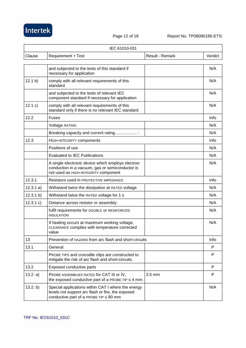
and subjected to the tests of this standard if necessary for application
N/A
12.1 b) comply with all relevant requirements of this standard
N/A
and subjected to the tests of relevant IEC component standard if necessary for application
N/A
12.1 c) comply with all relevant requirements of this standard only if there is no relevant IEC standard
N/A
12.2 Fuses Info
Voltage RATING N/A
Breaking capacity and current rating................... : N/A
12.3 HIGH-INTEGRITY components Info
Positions of use N/A
Evaluated to IEC Publications N/A
A single electronic device which employs electron conduction in a vacuum, gas or semiconductor is not used as HIGH-INTEGRITY component
N/A
12.3.1 Resistors used in PROTECTIVE IMPEDANCE Info
12.3.1 a) Withstand twice the dissipation at RATED voltage N/A
12.3.1 b) Withstand twice the RATED voltage for 1 s N/A
12.3.1 c) Distance across resistor or assembly: N/A
fulfil requirements for DOUBLE or REINFORCED INSULATION
N/A
If heating occurs at maximum working voltage, CLEARANCE complies with temperature corrected value
N/A
13 Prevention of HAZARD from arc flash and short-circuits Info
13.1 General P
PROBE TIPS and crocodile clips are constructed to mitigate the risk of arc flash and short-circuits.
P
13.2 Exposed conductive parts P
13.2. a) PROBE ASSEMBLIES RATED for CAT III or IV, the exposed conductive part of a PROBE TIP ≤ 4 mm.
3.5 mm P
13.2. b) Special applications within CAT I where the energy levels not support arc flash or fire, the exposed conductive part of a PROBE TIP ≤ 80 mm
N/A
Page 13 of 18 Report No. TP08090185-ETS:
IEC 61010-031
Clause Requirement + Test Result - Remark Verdict
TRF No. IEC61010_031C
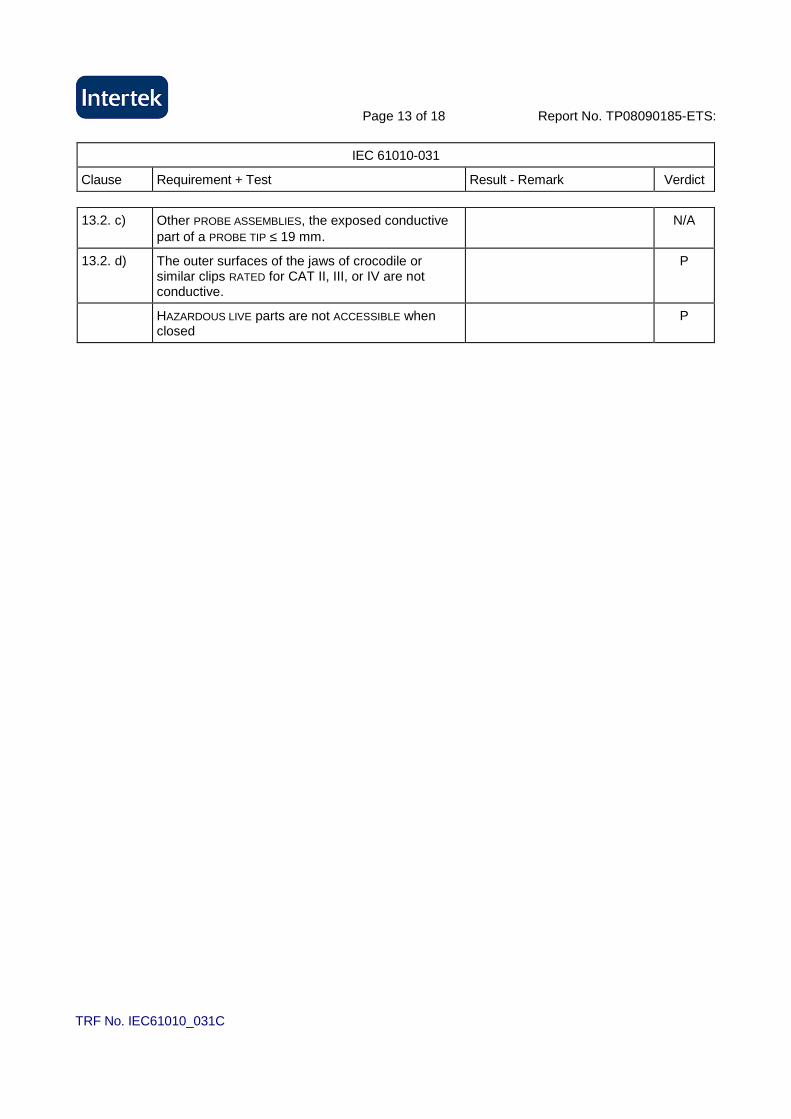
13.2. c) Other PROBE ASSEMBLIES, the exposed conductive part of a PROBE TIP ≤ 19 mm.
N/A
13.2. d) The outer surfaces of the jaws of crocodile or similar clips RATED for CAT II, III, or IV are not conductive.
P
HAZARDOUS LIVE parts are not ACCESSIBLE when closed
P

Page 14 of 18 Report No. TP08090185-ETS:
IEC 61010-031
Clause Requirement + Test Result - Remark Verdict
TRF No. IEC61010_031C
5.3 TABLE: Durability of markings P
Test agent .................................................. : Isopropyl alcohol
Marking location Remains
Legible
Label
Loose
Curled
Edges
Result
Identification (5.1.2) P P P P
Fuses (5.1.3) N/A N/A N/A N/A
TERMINALS and operating devices (5.1.4) N/A N/A N/A N/A
Parts protected by Double / Reinforced
equipment (5.1.5)
P P P P
RATING (5.1.6) P P P P
Warning marking (5.2) P P P P
6.3.1(2) TABLE: Voltage measured P
Parts between: Measured voltage (V)
in normal condition
Measured voltage (V)
In single fault condition
Probe tip to Cable 5 Vrms
Crocodile clip to Cable 6.08 Vrms
6.3.1(2) TABLE: Current measured N/A
Parts between: Current (mA)
in normal condition
Current (mA)
In single fault condition
6.3.1(2) TABLE: Capacitance measured N/A
Parts between: Capacitance
(µC)
Capacitance
(mJ)
Page 15 of 18 Report No. TP08090185-ETS:
IEC 61010-031
Clause Requirement + Test Result - Remark Verdict
TRF No. IEC61010_031C
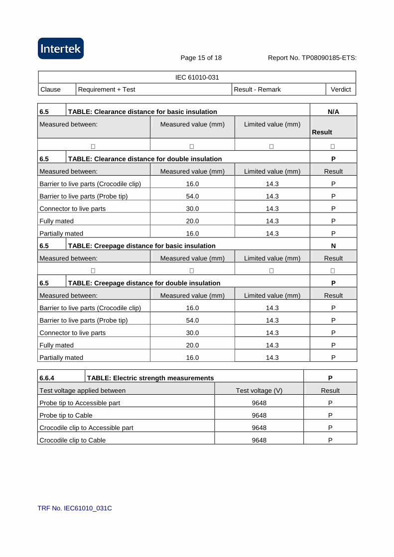
6.5 TABLE: Clearance distance for basic insulation N/A
Measured between: Measured value (mm) Limited value (mm) Result
6.5 TABLE: Clearance distance for double insulation P
Measured between: Measured value (mm) Limited value (mm) Result
Barrier to live parts (Crocodile clip) 16.0 14.3 P
Barrier to live parts (Probe tip) 54.0 14.3 P
Connector to live parts 30.0 14.3 P
Fully mated 20.0 14.3 P
Partially mated 16.0 14.3 P
6.5 TABLE: Creepage distance for basic insulation N
Measured between: Measured value (mm) Limited value (mm) Result
6.5 TABLE: Creepage distance for double insulation P
Measured between: Measured value (mm) Limited value (mm) Result
Barrier to live parts (Crocodile clip) 16.0 14.3 P
Barrier to live parts (Probe tip) 54.0 14.3 P
Connector to live parts 30.0 14.3 P
Fully mated 20.0 14.3 P
Partially mated 16.0 14.3 P
6.6.4 TABLE: Electric strength measurements P
Test voltage applied between Test voltage (V) Result
Probe tip to Accessible part 9648 P
Probe tip to Cable 9648 P
Crocodile clip to Accessible part 9648 P
Crocodile clip to Cable 9648 P
Page 16 of 18 Report No. TP08090185-ETS:
IEC 61010-031
Clause Requirement + Test Result - Remark Verdict
TRF No. IEC61010_031C
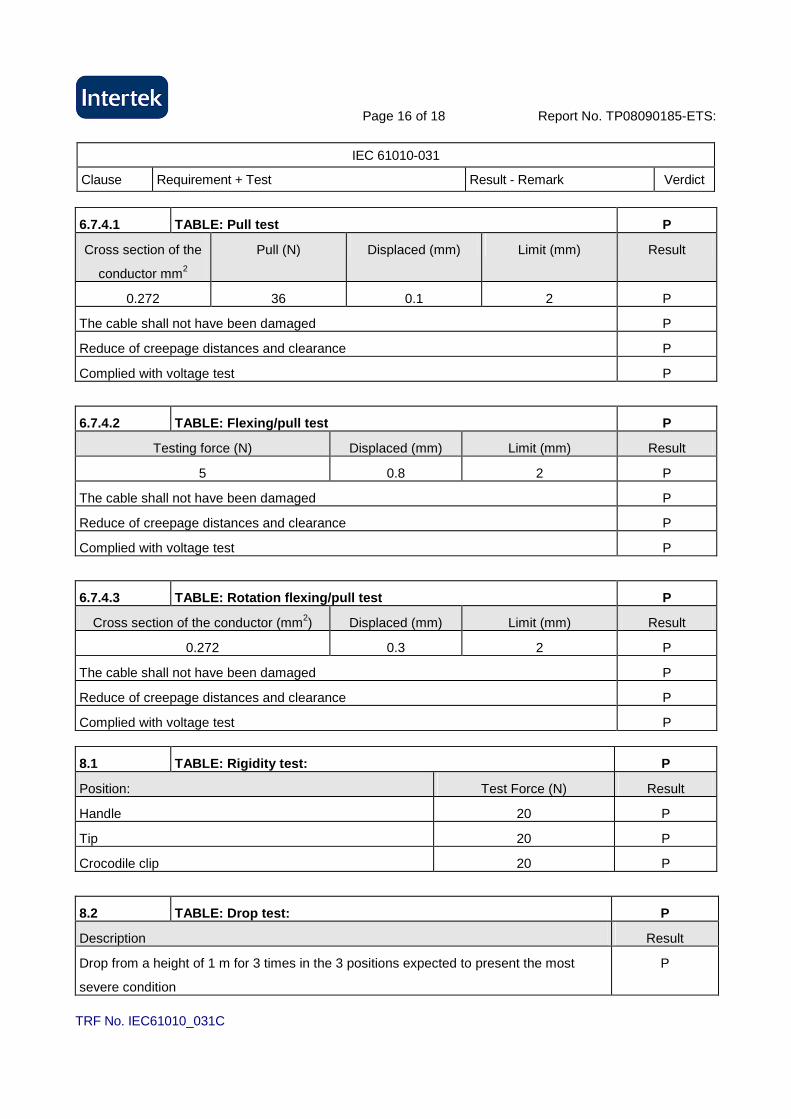
6.7.4.1 TABLE: Pull test P
Cross section of the
conductor mm2
Pull (N) Displaced (mm) Limit (mm) Result
0.272 36 0.1 2 P
The cable shall not have been damaged P
Reduce of creepage distances and clearance P
Complied with voltage test P
6.7.4.2 TABLE: Flexing/pull test P
Testing force (N) Displaced (mm) Limit (mm) Result
5 0.8 2 P
The cable shall not have been damaged P
Reduce of creepage distances and clearance P
Complied with voltage test P
6.7.4.3 TABLE: Rotation flexing/pull test P
Cross section of the conductor (mm2) Displaced (mm) Limit (mm) Result
0.272 0.3 2 P
The cable shall not have been damaged P
Reduce of creepage distances and clearance P
Complied with voltage test P
8.1 TABLE: Rigidity test: P
Position: Test Force (N) Result
Handle 20 P
Tip 20 P
Crocodile clip 20 P
8.2 TABLE: Drop test: P
Description Result
Drop from a height of 1 m for 3 times in the 3 positions expected to present the most
severe condition
P
Page 17 of 18 Report No. TP08090185-ETS:
IEC 61010-031
Clause Requirement + Test Result - Remark Verdict
TRF No. IEC61010_031C
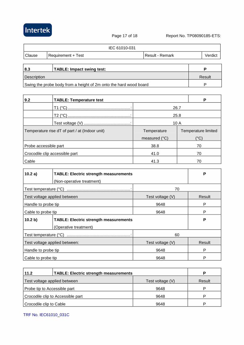
8.3 TABLE: Impact swing test: P
Description Result
Swing the probe body from a height of 2m onto the hard wood board P
9.2 TABLE: Temperature test P
T1 (°C) ....................................................... : 26.7
T2 (°C) .......................................................: 25.8
Test voltage (V) .........................................: 10 A
Temperature rise dT of part / at (Indoor unit) Temperature
measured (°C)
Temperature limited
(°C)
Probe accessible part 38.8 70
Crocodile clip accessible part 41.0 70
Cable 41.3 70
10.2 a) TABLE: Electric strength measurements
(Non-operative treatment)
P
Test temperature (°C) ........................................................ : 70
Test voltage applied between Test voltage (V) Result
Handle to probe tip 9648 P
Cable to probe tip 9648 P
10.2 b) TABLE: Electric strength measurements
(Operative treatment)
P
Test temperature (°C) ........................................................ : 60
Test voltage applied between: Test voltage (V) Result
Handle to probe tip 9648 P
Cable to probe tip 9648 P
11.2 TABLE: Electric strength measurements P
Test voltage applied between Test voltage (V) Result
Probe tip to Accessible part 9648 P
Crocodile clip to Accessible part 9648 P
Crocodile clip to Cable 9648 P
Page 18 of 18 Report No. TP08090185-ETS:
IEC 61010-031
Clause Requirement + Test Result - Remark Verdict
TRF No. IEC61010_031C
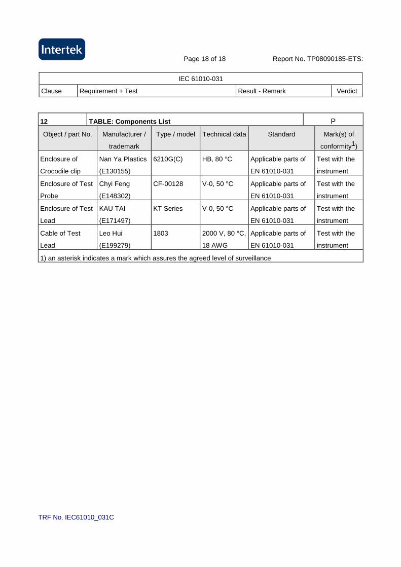
12 TABLE: Components List P
Object / part No. Manufacturer /
trademark
Type / model Technical data Standard Mark(s) of
conformity1)
Enclosure of
Crocodile clip
Nan Ya Plastics
(E130155)
6210G(C) HB, 80 °C Applicable parts of
EN 61010-031
Test with the
instrument
Enclosure of Test
Probe
Chyi Feng
(E148302)
CF-00128 V-0, 50 °C Applicable parts of
EN 61010-031
Test with the
instrument
Enclosure of Test
Lead
KAU TAI
(E171497)
KT Series V-0, 50 °C Applicable parts of
EN 61010-031
Test with the
instrument
Cable of Test
Lead
Leo Hui
(E199279)
1803 2000 V, 80 °C,
18 AWG
Applicable parts of
EN 61010-031
Test with the
instrument
1) an asterisk indicates a mark which assures the agreed level of surveillance

Page 1 of 2 Report No. : TP08090185-ETS ------------------------------------------------------------------------------------------------------------------------------------------------ Photo
TRF No. IEC61010_031C

Page 2 of 2 Report No. : TP08090185-ETS ------------------------------------------------------------------------------------------------------------------------------------------------ Photo
TRF No. IEC61010_031C