Embed Size (px)
Citation preview
SOFTWARE—PRACTICE AND EXPERIENCESoftw. Pract. Exper. 2008; 38:961–994Published online 3 October 2007 inWiley InterScience (www.interscience.wiley.com). DOI: 10.1002/spe.856
SUMLOW: early design-stagesketching of UML diagrams onan E-whiteboard
Qi Chen1, John Grundy1,2,∗,† and John Hosking1
1Department of Computer Science, University of Auckland, Private Bag 92019,Auckland, New Zealand2Department of Electrical and Electronic Engineering, University of Auckland,Private Bag 92019, Auckland, New Zealand
SUMMARY
Most visual diagramming tools provide point-and-click construction of computer-drawn diagram elementsusing a conventional desktop computer and mouse. SUMLOW is a unified modelling language (UML)diagramming tool that uses an electronic whiteboard (E-whiteboard) and sketching-based user interfaceto support collaborative software design. SUMLOW allows designers to sketch UML constructs, mixingdifferent UML diagram elements, diagram annotations, and hand-drawn text. A key novelty of the tool isthe preservation of hand-drawn diagrams and support for manipulation of these sketches using pen-basedactions. Sketched diagrams can be automatically ‘formalized’ into computer-recognized and -drawn UMLdiagrams and then exported to a third party CASE tool for further extension and use. We describe themotivation for SUMLOW, illustrate the use of the tool to sketch various UML diagram types, describeits key architecture abstractions and implementation approaches, and report on two evaluations of thetoolset. We hope that our experiences will be useful for others developing sketching-based design tools orthose looking to leverage pen-based interfaces in software applications. Copyright © 2007 John Wiley &Sons, Ltd.
Received 1 August 2006; Revised 23 August 2007; Accepted 27 August 2007
KEY WORDS: sketch-based user interfaces; E-whiteboards; CASE tools; unified modelling language; hand-drawnvisual language recognition
INTRODUCTION
Software designers often use whiteboards when carrying out collaborative design work. These areused to collaboratively draw and discuss preliminary software design ideas, for example as whole
∗Correspondence to: John Grundy, Department of Electrical and Electronic Engineering, University of Auckland, PrivateBag 92019, Auckland, New Zealand.
†E-mail: [email protected]
Copyright q 2007 John Wiley & Sons, Ltd.
962 Q. CHEN, J. GRUNDY AND J. HOSKING
(1)
(2)
(3)
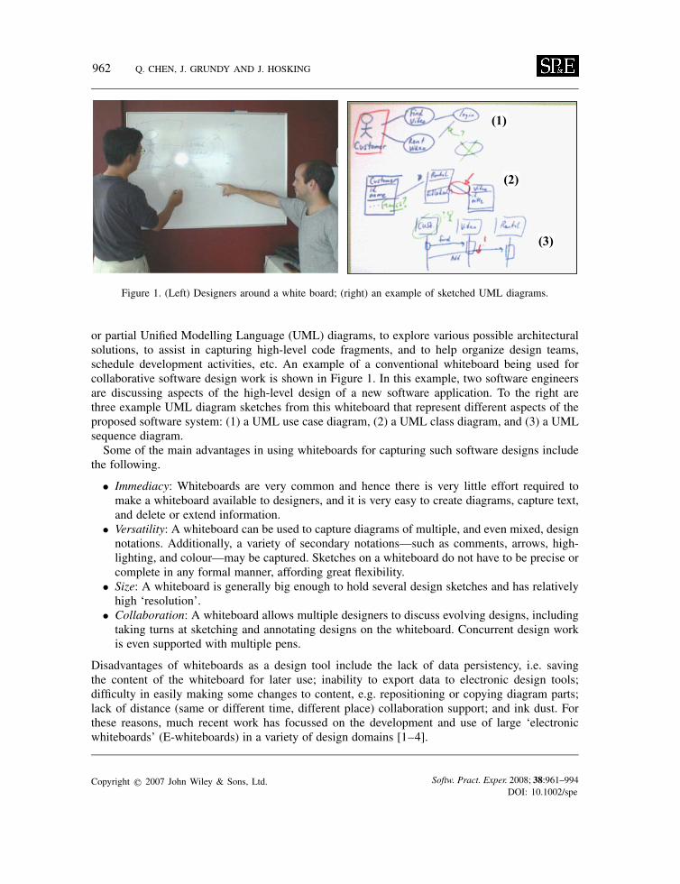
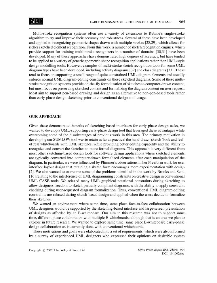
Figure 1. (Left) Designers around a white board; (right) an example of sketched UML diagrams.
or partial Unified Modelling Language (UML) diagrams, to explore various possible architecturalsolutions, to assist in capturing high-level code fragments, and to help organize design teams,schedule development activities, etc. An example of a conventional whiteboard being used forcollaborative software design work is shown in Figure 1. In this example, two software engineersare discussing aspects of the high-level design of a new software application. To the right arethree example UML diagram sketches from this whiteboard that represent different aspects of theproposed software system: (1) a UML use case diagram, (2) a UML class diagram, and (3) a UMLsequence diagram.Some of the main advantages in using whiteboards for capturing such software designs include
the following.
• Immediacy: Whiteboards are very common and hence there is very little effort required tomake a whiteboard available to designers, and it is very easy to create diagrams, capture text,and delete or extend information.
• Versatility: A whiteboard can be used to capture diagrams of multiple, and even mixed, designnotations. Additionally, a variety of secondary notations—such as comments, arrows, high-lighting, and colour—may be captured. Sketches on a whiteboard do not have to be precise orcomplete in any formal manner, affording great flexibility.
• Size: A whiteboard is generally big enough to hold several design sketches and has relativelyhigh ‘resolution’.
• Collaboration: A whiteboard allows multiple designers to discuss evolving designs, includingtaking turns at sketching and annotating designs on the whiteboard. Concurrent design workis even supported with multiple pens.
Disadvantages of whiteboards as a design tool include the lack of data persistency, i.e. savingthe content of the whiteboard for later use; inability to export data to electronic design tools;difficulty in easily making some changes to content, e.g. repositioning or copying diagram parts;lack of distance (same or different time, different place) collaboration support; and ink dust. Forthese reasons, much recent work has focussed on the development and use of large ‘electronicwhiteboards’ (E-whiteboards) in a variety of design domains [1–4].
Copyright q 2007 John Wiley & Sons, Ltd. Softw. Pract. Exper. 2008; 38:961–994DOI: 10.1002/spe
EARLY DESIGN-STAGE SKETCHING OF UML DIAGRAMS 963
In this paper we describe SUMLOW (Sketched UML On Whiteboard). SUMLOW provides anE-whiteboard-based early design-phase UML sketching and formalization tool. SUMLOW allowsUML diagrams to be sketched and recognized on an E-whiteboard and then these designs to beexported to a conventional CASE tool. SUMLOW is an experimental tool that we have used toexplore the feasibility of using sketching-based techniques for early-phase requirements and designmodelling on large-screen E-whiteboards. The key novelties of this proof-of-concept sketching-based design tool include
• the preservation of hand-sketched design elements—unlike most other sketching-based UMLdesign tools, sketches are not converted to formalized, computer-drawn sketches immediately;
• various pen-based manipulation facilities on sketches—users make use of various pen strokesto manipulate sketched diagrammatic elements;
• ability to selectively formalize sketches to computer-drawn diagrams and support for exportingthese to conventional CASE tools.
In the following section we firstly review related research into conventional software design tools,sketching-based design tools, E-whiteboard technologies, and sketching-based software designtools. We then describe the SUMLOW environment, architecture, and design, illustrating its usein a design scenario. Two evaluations of SUMLOW, a user survey and a Cognitive Dimension(CD)-based analysis, are presented. We conclude with a summary of the contributions of our workand future research plans.
RELATED WORK
UML diagrams may be used at many times during the software’s lifecycle to aid design and docu-mentation. During early design phases, e.g. requirements engineering and high-level architectureanalysis, diagrams are often more informal working sketches used to capture preliminary thinking.During detailed design and documentation phases, UML diagrams with more precise formal seman-tics are used to convey more details about the software code. Model-driven engineering even usessuch formal diagrams to generate code, possibly later modified in part by hand. Reverse engineeringtools draw UML diagrams at low and high levels of abstractions to show the structure of the targetcode.Many software tools have been developed that support UML diagramming [5,6], most of them
to support modelling of software designs. Almost all of these tools adopt conventional mouseand keyboard input and standard monitor display of information [7,8]. Taking up of such toolswithin organizations has been mixed at best [9–12]. Empirical studies show that designers findconventional CASE tools to be overly restrictive, during early design phases in particular, oftenleading to poor utilization of the tools [4,9,13]. A number of HCI studies have shown that developersprefer sketching designs by hand rather than using a keyboard and mouse, especially in the earlystages of software design [2,13,14]. Goel [15] and Black [10] have shown that designers reject toolsemploying conventional mouse-driven click-and-edit operations during early design-phase work.Diagram-editing constraints can also be very distracting and off-putting to users, especially duringcreative design work [9,16].Many approaches have been adopted to support collaborative work in conventional CASE
tools and other design environments [17–19]. Most of these approaches have focused on same
Copyright q 2007 John Wiley & Sons, Ltd. Softw. Pract. Exper. 2008; 38:961–994DOI: 10.1002/spe
964 Q. CHEN, J. GRUNDY AND J. HOSKING
time, different place (distributed synchronous) or different time, and different place (distributedasynchronous) collaboration. In general, these tools have also not had very successful uptake todate. Several studies have shown that use and sharing of hand-drawn sketches can better supportcollaboration during early-phase design [13,20,21]. In particular, same time, same place collab-orative early design-phase sketching approaches have proved to be successful in other domains[13,20].A number of design tools have been developed using a pen/sketch-based approach to overcome
some of the problems of mouse-based design environments. One of the earliest examples, SILK[14], provides a tool for software designers to sketch a user interface design using an electronicpad and stylus. SILK attempts to recognize the sketched user interface elements as soon as theyare drawn and to formalize them. This approach is not intrusive, however, and users are onlymade aware of the results when they choose to experiment with the design elements. The userinterface element recognition algorithm uses Rubine’s single-stroke gesture recognition algorithm[22]. SILK can transform the sketches of user interface elements into standard Motif widgets andgraphical objects when the designer has completed his or her sketching work. The designer canswitch the sketch into run mode to test the interface. Annotation and editing are also supportedby SILK to allow designs to be marked up to facilitate discussion and for sketched designs to bemodified easily. However, SILK recognizes only a few ways of drawing each widget and does notsupport specification of widget behaviour. Other related user interface work include web-based userinterface design in Denim [23] and prototype gesture-based document manipulation tools [24,25].E-whiteboards have become increasingly popular to support a number of design-related activities.
These include facilitation of meetings with collaborative document display and annotation [26],computing education [3], Power-PointTM presentation control and annotation [24], and (early-phase)software design [4]. The previously listed main advantages of conventional whiteboards are partiallyreplicated with E-whiteboard applications, with additional advantages of data capture and display,distributed work support and control by gesture-based interfaces [1,3,24].FreeForm [2] is a Visual Basic (VB) add-In for the design of VB user interface forms. FreeForm
uses the same metaphor as SILK, but utilizes an E-whiteboard to support sketching-based UI design.Both shape and character recognition use modified forms of Rubine’s [22] algorithm. Plimmerdiscovered via experiments with end users that retention of sketches during user testing of formsimproved the quality of testing over conversion to VB forms and hence the quality of the softwaredesign.Knight is a widely known UML design tool that uses gestures on an E-whiteboard with pen input
[13]. A number of similar tools have been developed for UML-based software design with sketching-based input of diagram elements [4,27]. Some preliminary work has also been done on recognizingUML diagram shapes from glyphs [4]. Most of these tools support UML diagramming by strokerecognition and immediate conversion of the sketched elements into computer-drawn, formalizedUML diagram elements. Knight uses two methods to support input and recognition—compoundgestures combine gestures that are close in either time or space to form one drawing element. Eagerrecognition uses Rubine’s algorithm to try and classify shapes while they are being input by theuser. Text input is supported by keyboard, on-screen Virtual Keyboard or stylus-based gestures.Most existing UML sketching tools currently adopt immediate recognition and formalization ofUML diagram elements. Some allow incomplete elements to be recognized at a later time. However,there is usually no association between a sketched element and a formalized element, the sketchedcontent usually being lost once recognition has been done.
Copyright q 2007 John Wiley & Sons, Ltd. Softw. Pract. Exper. 2008; 38:961–994DOI: 10.1002/spe
EARLY DESIGN-STAGE SKETCHING OF UML DIAGRAMS 965
Multi-stroke recognition systems often use a variety of extensions to Rubine’s single-strokealgorithm to try and improve their accuracy and robustness. Several of these have been developedand applied to recognizing geometric shapes drawn with multiple strokes [28,29], which allows forricher sketched element recognition. From this work, a number of sketch recognition engines, whichprovide support for training multi-stroke recognizers in a number of domains [30,31] have beendeveloped. Many of these approaches have demonstrated high degrees of accuracy, but have tendedto be applied to a variety of generic geometric shape recognition applications rather than UML-styledesign modelling tools. However, examples of multi-stroke sketch recognition tools for some UMLdiagram types have been developed, including activity diagrams [32] and class diagrams [33]. Thesetend to focus on supporting a small range of quite constrained UML diagram elements and usuallyenforce normal UML diagram-editing constraints on these sketched diagrams. Some of these multi-stroke recognition systems provide on-the-fly formalization of sketches to computer-drawn content,but most focus on preserving sketched content and formalizing the diagram content on user request.Most aim to support pen-based drawing and design as an alternative to non-pen-based tools ratherthan early-phase design sketching prior to conventional design tool usage.
OUR APPROACH
Given these demonstrated benefits of sketching-based interfaces for early-phase design tasks, wewanted to develop a UML-supporting early-phase design tool that leveraged these advantages whileovercoming some of the disadvantages of previous work in this area. The primary motivation indeveloping our SUMLOW tool was to retain as far as practical the hand-drawn sketch ‘look and feel’of real whiteboards with UML sketches, while providing better editing capability and the ability torecognize and convert the sketches to more formal diagrams. This approach is very different frommost other sketching-based design tools for software design applications where sketched elementsare typically converted into computer-drawn formalized elements after each manipulation of thediagram. In particular, we were influenced by Plimmer’s observations in her Freeform work for userinterface layout design that retaining a sketch form encourages more experimentation with design[2]. We also wanted to overcome some of the problems identified in the work by Brooks and Scott[16] relating to the interference of UML diagramming constraints on creative design in conventionalUML CASE tools. We relaxed many UML graphical notational constraints during sketching toallow designers freedom to sketch partially compliant diagrams, with the ability to apply constraintchecking during user-requested diagram formalization. Thus, conventional UML diagram-editingconstraints are relaxed during sketch-based design and applied when the users decide to formalizetheir sketches.We wanted an environment where same time, same place face-to-face collaboration between
UML designers would be supported by the sketching-based interface and large-screen presentationof designs as afforded by an E-whiteboard. Our aim in this research was not to support sametime, different place collaboration with multiple E-whiteboards, although that is an area we plan toexplore in future research. We wanted to explore same time, same place E-whiteboard early-phasedesign collaboration as is currently done with conventional whiteboards.These motivations and goals were elaborated into a set of requirements, which were also informed
by a survey of experienced UML designers who expressed their opinions on desirable system
Copyright q 2007 John Wiley & Sons, Ltd. Softw. Pract. Exper. 2008; 38:961–994DOI: 10.1002/spe
966 Q. CHEN, J. GRUNDY AND J. HOSKING
features. A summary of SUMLOW’s requirements is as follows:
• A pen-based E-whiteboard system that supports sketching of a core set of UML diagramswhile retaining the sketch ‘look and feel’.
• Progressive recognition and formalization of diagram elements, but with minimal interruptionto the user while sketching, and with good performance and accuracy of the capture andrecognition algorithms used.
• Early design-phase work as the focus, with UML diagram constraints not interfering with thesketching process.
• Functionality to edit sketched diagrams without destroying the sketch look and feel.• Ability to use a wide variety of secondary notation, such as colour, annotations, etc.• Support for persistency of sketches and recognized UML diagrams and constructs, and the
ability to export to a conventional UML tool.• Same time, same place face-to-face design collaboration supported via a large-screen
E-whiteboard and either multiple or shared sketching pens.
Our approach to meeting these requirements is an E-whiteboard-based sketching tool thatrecognizes UML constructs as they are drawn but preserves the hand-drawn look-and-feel inter-face throughout the design phase. This differs significantly from other existing UML sketchingapproaches such as Knight [4,13,27]. In SUMLOW, the look and feel of the hand-drawn constructsare always retained while still allowing sketched elements to be moved, resized, copied, replaced,deleted, etc. via pen-based input techniques. Rich, user-defined secondary notation is supported ina seamless way by use of textual annotations, colour, arbitrary sketches, etc.The need to support early design-phase work meant that, unlike in almost all UML-based CASE
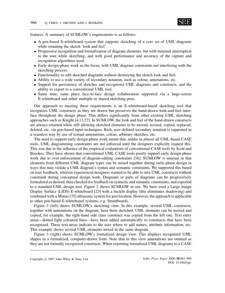
tools, UML diagramming constraints are not enforced until the designers explicitly request this.This was due to the influence of the empirical evaluations of conventional CASE tools by Scott andBrookes. They have shown that conventional UML CASE tools poorly support early design-phasework due to over-enforcement of diagram-editing constraints [16]. SUMLOW is unusual in thatelements from different UML diagram types can be mixed together during early-phase design inways that may violate a UML diagram’s syntax and semantic constraints. We supported this basedon user feedback, wherein experienced designers wanted to be able to mix UML constructs withoutconstraint during conceptual design work. Diagrams or parts of diagrams can be progressivelyformalized as desired, then checked for feedback on syntactic and semantic constraints, and exportedto a standard UML design tool. Figure 2 shows SUMLOW in use. We have used a Large ImageDisplay Surface (LIDS) E-whiteboard [23] with a backlit display (this eliminates shadowing) andcombined with aMimio [35] ultrasonic system for pen location. However, the approach is applicableto other pen-based E-whiteboard systems, e.g. Smartboards.Figure 3 (left) shows SUMLOW’s sketching view. In this example, several UML constructs,
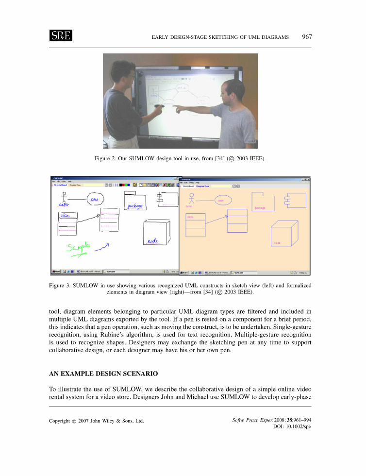
together with annotations on the diagram, have been sketched. UML elements can be moved andcopied, for example, the right-hand side class construct was copied from the left one. Text entryareas—dotted light coloured lines—have been added automatically to constructs that have beenrecognized. These text areas indicate to the user where to add names, attribute information, etc.This example shows several UML elements mixed in the same diagram.Figure 3 (right) shows SUMLOW’s formalized design view. This displays recognized UML
shapes in a formalized, computer-drawn form. Note that in this view annotations are omitted asthey are not formally recognized constructs. When exporting formalized UML diagrams to a CASE
Copyright q 2007 John Wiley & Sons, Ltd. Softw. Pract. Exper. 2008; 38:961–994DOI: 10.1002/spe
EARLY DESIGN-STAGE SKETCHING OF UML DIAGRAMS 967
Figure 2. Our SUMLOW design tool in use, from [34] ( c© 2003 IEEE).
Figure 3. SUMLOW in use showing various recognized UML constructs in sketch view (left) and formalizedelements in diagram view (right)—from [34] ( c© 2003 IEEE).
tool, diagram elements belonging to particular UML diagram types are filtered and included inmultiple UML diagrams exported by the tool. If a pen is rested on a component for a brief period,this indicates that a pen operation, such as moving the construct, is to be undertaken. Single-gesturerecognition, using Rubine’s algorithm, is used for text recognition. Multiple-gesture recognitionis used to recognize shapes. Designers may exchange the sketching pen at any time to supportcollaborative design, or each designer may have his or her own pen.
AN EXAMPLE DESIGN SCENARIO
To illustrate the use of SUMLOW, we describe the collaborative design of a simple online videorental system for a video store. Designers John and Michael use SUMLOW to develop early-phase
Copyright q 2007 John Wiley & Sons, Ltd. Softw. Pract. Exper. 2008; 38:961–994DOI: 10.1002/spe
968 Q. CHEN, J. GRUNDY AND J. HOSKING
Accounts System
Maintain Customers
Rent/Return VideoStaff Members
ManagementReports & Fines
Maintain Videos
Inventory System
1Person
ID : intName : Stringage : intpassword : String
StaffPosition: Stringsalary : real
addStaff()updateStaff()findStaff(int id)
0..*
1..1
0..*
1..1
CustomerAddress : stringphone : string
findcustomer()addCustomer()updatecustomer()deletecustomer()findVideo()
0..*1..1
0..*1..1 rents
VideoID : intName : StringCategory : StringCost : realNumNights : intRating : StringnumCopies: integer
findVideo()findByName()setNumCopies()
uses
1..11..1
rents
Rental
Date : StringReturned : boolean
addRental()findRental()
rentVideo()
returnVideo()
2
Rental Object :Rental
CustomerObject :
Video Object : Video
Staff Object :Staff
addRental(…)
findcustomer(int id)
findVideo(int id)
findStaff(ind id)
setNumCopies(int)
3
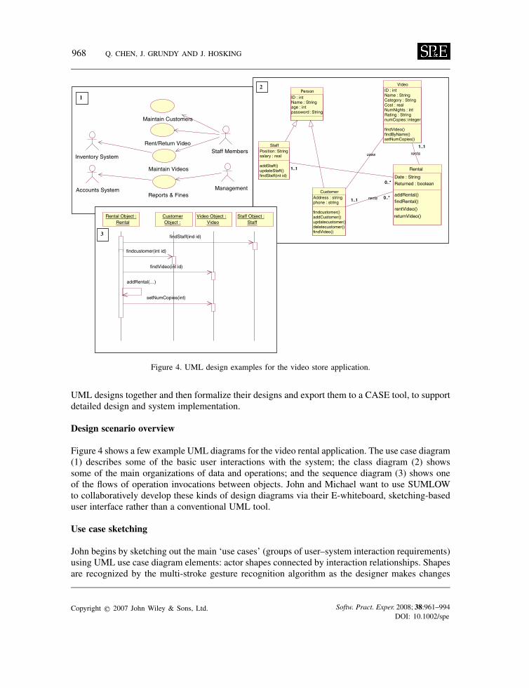
Figure 4. UML design examples for the video store application.
UML designs together and then formalize their designs and export them to a CASE tool, to supportdetailed design and system implementation.
Design scenario overview
Figure 4 shows a few example UML diagrams for the video rental application. The use case diagram(1) describes some of the basic user interactions with the system; the class diagram (2) showssome of the main organizations of data and operations; and the sequence diagram (3) shows oneof the flows of operation invocations between objects. John and Michael want to use SUMLOWto collaboratively develop these kinds of design diagrams via their E-whiteboard, sketching-baseduser interface rather than a conventional UML tool.
Use case sketching
John begins by sketching out the main ‘use cases’ (groups of user–system interaction requirements)using UML use case diagram elements: actor shapes connected by interaction relationships. Shapesare recognized by the multi-stroke gesture recognition algorithm as the designer makes changes
Copyright q 2007 John Wiley & Sons, Ltd. Softw. Pract. Exper. 2008; 38:961–994DOI: 10.1002/spe
EARLY DESIGN-STAGE SKETCHING OF UML DIAGRAMS 969
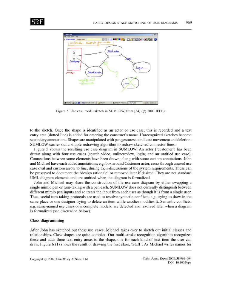
Figure 5. Use case model sketch in SUMLOW, from [34] ( c© 2003 IEEE).
to the sketch. Once the shape is identified as an actor or use case, this is recorded and a textentry area (dotted line) is added for entering the construct’s name. Unrecognized sketches becomesecondary annotations. Shapes aremanipulated with pen gestures to indicate movement and deletion.SUMLOW carries out a simple redrawing algorithm to redraw sketched connector lines.Figure 5 shows the resulting use case diagram in SUMLOW. An actor (‘customer’) has been
drawn along with four use cases (search video, onlinereview, login, and an untitled use case).Connections between some elements have been drawn, along with some custom annotations. JohnandMichael have each added annotations, e.g. box around Customer actor, cross through unused usecase oval and custom arrow to line, during their discussions of the system requirements. These canbe preserved to document the ‘design rationale’ or removed later if desired. They are not standardUML diagram elements and are omitted when the diagram is formalized.John and Michael may share the construction of the use case diagram by either swapping a
single mimio pen or turn-taking with a pen each. SUMLOW does not currently distinguish betweendifferent mimio pen inputs and so treats the input from each user as though it is from a single user.Thus, social turn-taking protocols are used to resolve syntactic conflicts, e.g. trying to draw in thesame place or one designer trying to delete an item while another modifies it. Semantic conflicts,e.g. same-named use cases or incomplete models, are detected and resolved later when a diagramis formalized (see discussion below).
Class diagramming
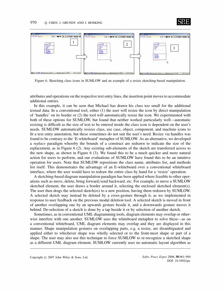
After John has sketched out these use cases, Michael takes over to sketch out initial classes andrelationships. Class shapes are quite complex. Our multi-stroke recognition algorithm recognizesthese and adds three text entry areas to the shape, one for each kind of text item the user candraw. Figure 6 (1) shows the result of drawing the first class, ‘Staff’. As Michael writes names for
Copyright q 2007 John Wiley & Sons, Ltd. Softw. Pract. Exper. 2008; 38:961–994DOI: 10.1002/spe
970 Q. CHEN, J. GRUNDY AND J. HOSKING
Figure 6. Sketching class icons in SUMLOW and an example of a resize sketching-based manipulation.
attributes and operations on the respective text entry lines, the insertion point moves to accommodateadditional entries.In this example, it can be seen that Michael has drawn his class too small for the additional
textual data. In a conventional tool, either (1) the user will resize the icon by direct manipulationof ‘handles’ on its border or (2) the tool will automatically resize the icon. We experimented withboth of these options for SUMLOW, but found that neither worked particularly well—automaticresizing is difficult as the size of text to be entered inside the class icon is dependent on the user’sneeds. SUMLOW automatically resizes class, use case, object, component, and machine icons tofit a text entry annotation, but these sometimes do not suit the user’s need. Resize via handles wasfound to be contrary to the ‘E-whiteboard’ metaphor of SUMLOW. As an alternative, we developeda replace paradigm whereby the bounds of a construct are redrawn to indicate the size of thereplacement, as in Figure 6 (2). Any existing sub-elements of the sketch are transferred across tothe new shape, as shown in Figure 6 (3). We found this to be a much quicker and more naturalaction for users to perform, and our evaluations of SUMLOW have found this to be an intuitiveoperation for users. Note that SUMLOW repositions the class name, attributes list, and methodslist itself. This demonstrates the advantage of an E-whiteboard over a conventional whiteboardinterface, where the user would have to redraw the entire class by hand for a ‘resize’ operation.A sketching-based diagram manipulation paradigm has been applied where feasible to other oper-
ations such as move, delete, bring forward/send backward, etc. For example, to move a SUMLOWsketched element, the user draws a border around it, selecting the enclosed sketched element(s).The user then drags the selected sketch(es) to a new position, having them redrawn by SUMLOW.A selected sketch may instead be deleted by a cross-gesture through it, as we implemented inresponse to user feedback on the previous modal deletion tool. A selected sketch is moved in frontof another overlapping one by an upwards gesture beside it, and a downwards gesture moves itbehind. De-selection of a sketch is done by a tap beside it or by selection of another sketch.Sometimes, as in conventional UML diagramming tools, diagram elements may overlap or other-
wise interfere with one another. SUMLOW uses the whiteboard metaphor to solve these—as ona conventional whiteboard, UML diagram elements may overlap and they are displayed in thismanner. Shape manipulation gestures on overlapping parts, e.g. a resize, are disambiguated andapplied either to whichever shape was wholly selected or to the front-most shape or part of ashape. The user may also use this technique to force SUMLOW to re-recognize a sketched shapeas a different UML diagram element. SUMLOW currently uses no automatic layout algorithm as
Copyright q 2007 John Wiley & Sons, Ltd. Softw. Pract. Exper. 2008; 38:961–994DOI: 10.1002/spe

EARLY DESIGN-STAGE SKETCHING OF UML DIAGRAMS 971
Figure 7. UML class diagram sketch in SUMLOW, from [34] ( c© 2003 IEEE).
these have been shown to significantly interfere with early design-phase work [16]. Users mustmanipulate diagram elements explicitly to affect resizing and moving.One difference between SUMLOW and conventional UML tools is when a modelling icon, e.g.
class shape, is deleted. In conventional tools, relationship icons disappear if either associated endis deleted. SUMLOW users often sketch another element to replace the one deleted and prefer therelationship to be kept instead of having to draw another one. The user may manually delete a‘dangling’ relationship if necessary with a single cross-gesture over it with the pen. As the kindof relationship between icons is dependent on the connected icon types themselves, recognition ofrelationship type is deferred until both source and target icons have been recognized. If one of theseis deleted, the relationship type is made ‘unknown’ until another source or target has been drawnand recognized by SUMLOW.A more complete UML class diagram sketch is shown in Figure 7, with several classes, associ-
ations and generalizations. Here, Michael has named classes and added attributes and operationsto three of them. An extra use case sketch is added at the top left (boxed off). During designdiscussions, John and he have also added textual annotation, arrows and shape highlights that arenot recognized as UML constructs and are hence regarded as secondary notation.John and Michael may revisit their use case diagram(s) during or after class diagram design
and may use constructs from use case diagrams in the class diagrams, as shown in Figure 7.Conventional UML CASE tools disallow this mixed use of diagram elements, enforcing a rigiddefinition of diagram types and symbols. SUMLOW in contrast aims at providing more flexibilityto the designers to mix and match notational symbols as they wish during sketching design.
UML sequence diagrams
After discussing and modifying the initial class diagram sketch, John and Michael focus on acomplex message flow in the video system design, sketching a sequence diagram to capture and
Copyright q 2007 John Wiley & Sons, Ltd. Softw. Pract. Exper. 2008; 38:961–994DOI: 10.1002/spe
972 Q. CHEN, J. GRUNDY AND J. HOSKING
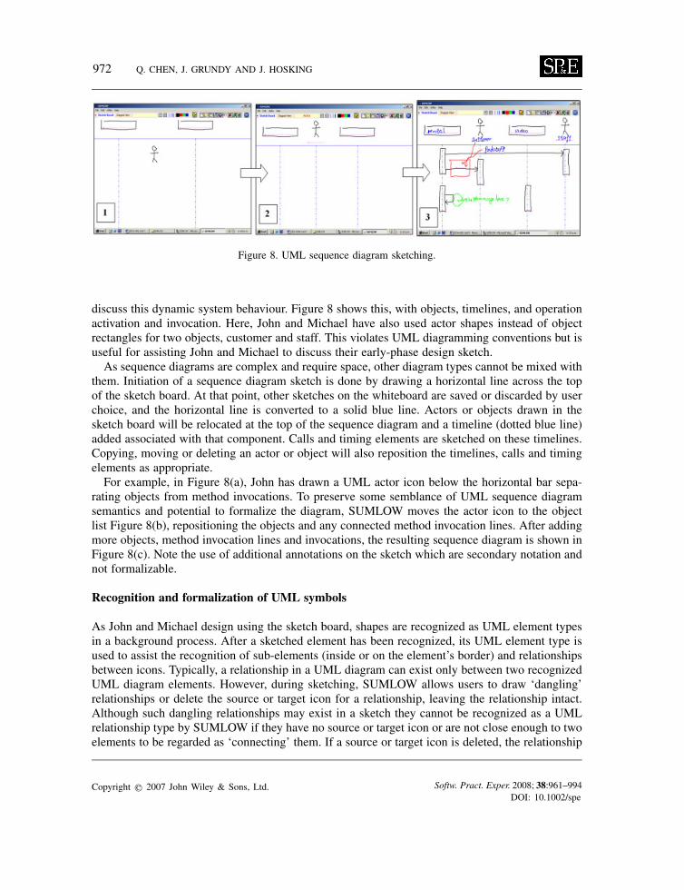
Figure 8. UML sequence diagram sketching.
discuss this dynamic system behaviour. Figure 8 shows this, with objects, timelines, and operationactivation and invocation. Here, John and Michael have also used actor shapes instead of objectrectangles for two objects, customer and staff. This violates UML diagramming conventions but isuseful for assisting John and Michael to discuss their early-phase design sketch.As sequence diagrams are complex and require space, other diagram types cannot be mixed with
them. Initiation of a sequence diagram sketch is done by drawing a horizontal line across the topof the sketch board. At that point, other sketches on the whiteboard are saved or discarded by userchoice, and the horizontal line is converted to a solid blue line. Actors or objects drawn in thesketch board will be relocated at the top of the sequence diagram and a timeline (dotted blue line)added associated with that component. Calls and timing elements are sketched on these timelines.Copying, moving or deleting an actor or object will also reposition the timelines, calls and timingelements as appropriate.For example, in Figure 8(a), John has drawn a UML actor icon below the horizontal bar sepa-
rating objects from method invocations. To preserve some semblance of UML sequence diagramsemantics and potential to formalize the diagram, SUMLOW moves the actor icon to the objectlist Figure 8(b), repositioning the objects and any connected method invocation lines. After addingmore objects, method invocation lines and invocations, the resulting sequence diagram is shown inFigure 8(c). Note the use of additional annotations on the sketch which are secondary notation andnot formalizable.
Recognition and formalization of UML symbols
As John and Michael design using the sketch board, shapes are recognized as UML element typesin a background process. After a sketched element has been recognized, its UML element type isused to assist the recognition of sub-elements (inside or on the element’s border) and relationshipsbetween icons. Typically, a relationship in a UML diagram can exist only between two recognizedUML diagram elements. However, during sketching, SUMLOW allows users to draw ‘dangling’relationships or delete the source or target icon for a relationship, leaving the relationship intact.Although such dangling relationships may exist in a sketch they cannot be recognized as a UMLrelationship type by SUMLOW if they have no source or target icon or are not close enough to twoelements to be regarded as ‘connecting’ them. If a source or target icon is deleted, the relationship
Copyright q 2007 John Wiley & Sons, Ltd. Softw. Pract. Exper. 2008; 38:961–994DOI: 10.1002/spe
EARLY DESIGN-STAGE SKETCHING OF UML DIAGRAMS 973
becomes unrecognized until another is drawn in its place, when the shape recognition processattempts to re-categorize its UML relationship type.SUMLOW provides a ‘UML design view’ which renders the recognized UML elements in a
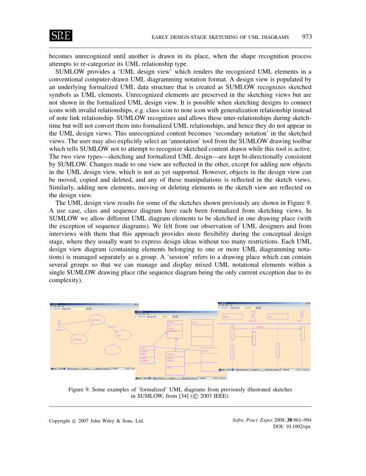
conventional computer-drawn UML diagramming notation format. A design view is populated byan underlying formalized UML data structure that is created as SUMLOW recognizes sketchedsymbols as UML elements. Unrecognized elements are preserved in the sketching views but arenot shown in the formalized UML design view. It is possible when sketching designs to connecticons with invalid relationships, e.g. class icon to note icon with generalization relationship insteadof note link relationship. SUMLOW recognizes and allows these inter-relationships during sketch-time but will not convert them into formalized UML relationships, and hence they do not appear inthe UML design views. This unrecognized content becomes ‘secondary notation’ in the sketchedviews. The user may also explicitly select an ‘annotation’ tool from the SUMLOW drawing toolbarwhich tells SUMLOW not to attempt to recognize sketched content drawn while this tool is active.The two view types—sketching and formalized UML design—are kept bi-directionally consistentby SUMLOW. Changes made to one view are reflected in the other, except for adding new objectsin the UML design view, which is not as yet supported. However, objects in the design view canbe moved, copied and deleted, and any of these manipulations is reflected in the sketch views.Similarly, adding new elements, moving or deleting elements in the sketch view are reflected onthe design view.The UML design view results for some of the sketches shown previously are shown in Figure 9.
A use case, class and sequence diagram have each been formalized from sketching views. InSUMLOW we allow different UML diagram elements to be sketched in one drawing place (withthe exception of sequence diagrams). We felt from our observation of UML designers and frominterviews with them that this approach provides more flexibility during the conceptual designstage, where they usually want to express design ideas without too many restrictions. Each UMLdesign view diagram (containing elements belonging to one or more UML diagramming nota-tions) is managed separately as a group. A ‘session’ refers to a drawing place which can containseveral groups so that we can manage and display mixed UML notational elements within asingle SUMLOW drawing place (the sequence diagram being the only current exception due to itscomplexity).
Figure 9. Some examples of ‘formalized’ UML diagrams from previously illustrated sketchesin SUMLOW, from [34] ( c© 2003 IEEE).
Copyright q 2007 John Wiley & Sons, Ltd. Softw. Pract. Exper. 2008; 38:961–994DOI: 10.1002/spe
974 Q. CHEN, J. GRUNDY AND J. HOSKING
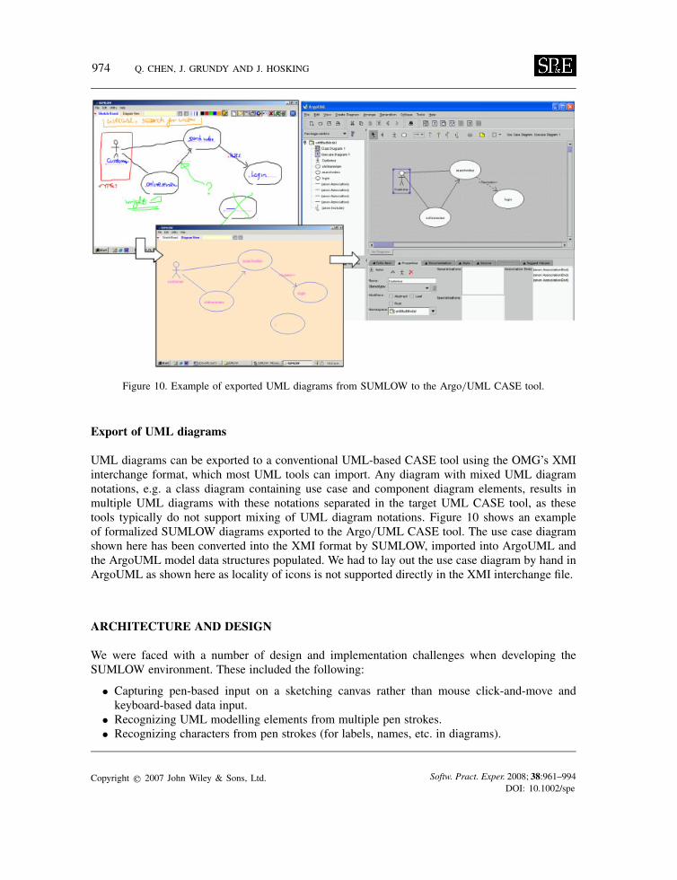
Figure 10. Example of exported UML diagrams from SUMLOW to the Argo/UML CASE tool.
Export of UML diagrams
UML diagrams can be exported to a conventional UML-based CASE tool using the OMG’s XMIinterchange format, which most UML tools can import. Any diagram with mixed UML diagramnotations, e.g. a class diagram containing use case and component diagram elements, results inmultiple UML diagrams with these notations separated in the target UML CASE tool, as thesetools typically do not support mixing of UML diagram notations. Figure 10 shows an exampleof formalized SUMLOW diagrams exported to the Argo/UML CASE tool. The use case diagramshown here has been converted into the XMI format by SUMLOW, imported into ArgoUML andthe ArgoUML model data structures populated. We had to lay out the use case diagram by hand inArgoUML as shown here as locality of icons is not supported directly in the XMI interchange file.
ARCHITECTURE AND DESIGN
We were faced with a number of design and implementation challenges when developing theSUMLOW environment. These included the following:
• Capturing pen-based input on a sketching canvas rather than mouse click-and-move andkeyboard-based data input.
• Recognizing UML modelling elements from multiple pen strokes.• Recognizing characters from pen strokes (for labels, names, etc. in diagrams).
Copyright q 2007 John Wiley & Sons, Ltd. Softw. Pract. Exper. 2008; 38:961–994DOI: 10.1002/spe
EARLY DESIGN-STAGE SKETCHING OF UML DIAGRAMS 975
• Supporting manipulation of UML diagram elements by pen-based gestures rather than conven-tional point-and-click direct manipulation techniques.
• Preserving the sketched look-and-feel of diagram elements under gesture-based manipulationslike move and resize.
• Storing complex UML sketched diagrams, formalized diagrams, and their underlying designmodels in appropriate data structures.
• Generating XMI interchange format files to export SUMLOW formalized designs to conven-tional UML CASE tools.
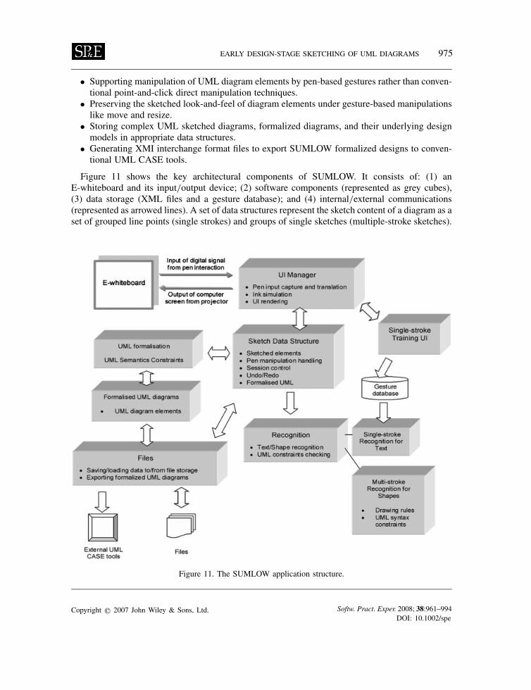
Figure 11 shows the key architectural components of SUMLOW. It consists of: (1) anE-whiteboard and its input/output device; (2) software components (represented as grey cubes),(3) data storage (XML files and a gesture database); and (4) internal/external communications(represented as arrowed lines). A set of data structures represent the sketch content of a diagram as aset of grouped line points (single strokes) and groups of single sketches (multiple-stroke sketches).
Figure 11. The SUMLOW application structure.
Copyright q 2007 John Wiley & Sons, Ltd. Softw. Pract. Exper. 2008; 38:961–994DOI: 10.1002/spe
976 Q. CHEN, J. GRUNDY AND J. HOSKING
A second data structure represents formalized UML content with recognized UML elements linkedto their single- or multi-stroke sketch input. These data structures may be saved and loaded toSUMLOW files and the UML elements exported to an XMI tool inter-change format. User inputmanipulates the sketch data structures, with the recognition system driven by events generated bychanges to the sketch data structure. Sketched elements are annotated with a recognized elementtype that is used to inform further recognition of related sub-elements and relationships, and toassist user interaction, e.g. by the tool proactively adding text entry annotations to the sketch.A single-stroke text recognizer is currently used to identify text and stores the text value withsketched elements. On user request, the sketched content is converted into the formalized UMLdata structure. The following sections explain the design of each of these key parts of SUMLOW’sarchitecture.
Data structures
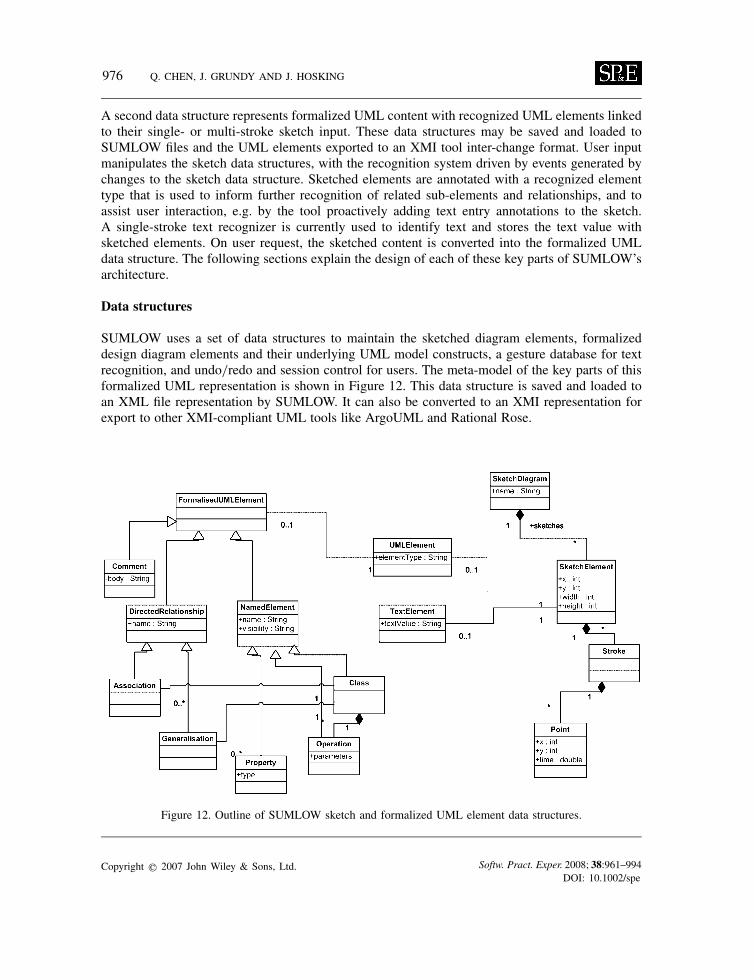
SUMLOW uses a set of data structures to maintain the sketched diagram elements, formalizeddesign diagram elements and their underlying UML model constructs, a gesture database for textrecognition, and undo/redo and session control for users. The meta-model of the key parts of thisformalized UML representation is shown in Figure 12. This data structure is saved and loaded toan XML file representation by SUMLOW. It can also be converted to an XMI representation forexport to other XMI-compliant UML tools like ArgoUML and Rational Rose.
Figure 12. Outline of SUMLOW sketch and formalized UML element data structures.
Copyright q 2007 John Wiley & Sons, Ltd. Softw. Pract. Exper. 2008; 38:961–994DOI: 10.1002/spe
EARLY DESIGN-STAGE SKETCHING OF UML DIAGRAMS 977
Sketches are made up of one or more ‘Stroke’ objects, with each stroke represented as a set ofconnected points. Mouse movement events from the user interface are used to create each Strokeand these strokes are grouped into a sketch element by the shape and text recognizers. A sketch mayhave been recognized as a UML construct—i.e. a set of strokes making up a UML element—oras text, i.e. a set of strokes making up a line of text. If the shape recognizer identifies a set ofstrokes as relating to a UML element, then it groups these strokes into a single sketch element andindicates the UML element type that the sketch corresponds to. Text is recognized by a separate,single-stroke text recognizer. The text recognizer groups a set of strokes, each stroke correspondingto a single character, into a line of text and the textual string corresponding to the sketched textinput. Formalized UML design diagrams are represented in a conventional object-oriented manner,but with a relationship to the sketch element they are derived from. A model-view approach is usedto associate sketched elements and formalized design diagram elements with UML model elements.This supports multiple views of a model element in different SUMLOW sketch diagrams andformalized design diagrams. We developed a data structure loosely based on the UML meta-modelto hold our formalized UML diagram information in SUMLOW.
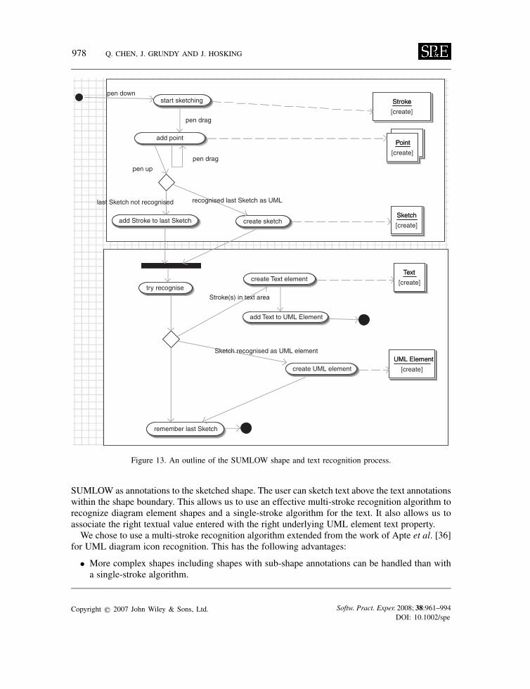
Recognition process
Figure 13 shows an outline of the process used when drawing strokes, recognizing a set of strokes asa UML element or text and grouping strokes into sketch elements. Initially, the user begins sketchingby repeatedly putting his or her pen down, dragging it and releasing it. Each of these actionscreates a stroke, which records the pen’s movements as a set of Points. At each pen up, SUMLOWeither creates a new sketch element with the new stroke (if the last Sketch was recognized) orattempts to recognize the new stroke when added to the previous sketch (if certain timing andproximity heuristics are met, i.e. the new stroke occurs very recently after the previous was drawnand some point within it overlaps or is close to the previous sketch’s strokes). SUMLOW thentries to recognize the composite sketch element as text—if it has been drawn above an annotation(illustrated previously)—or as a UML element (using the multi-stroke recognition process describedbelow). The text recognizer assumes one stroke per character (described in detail below). TheUML element recognizer uses a multi-stroke recognizer (also described in detail below). If text isrecognized, a text object is created and added to the UML element the text annotation belongs to.If a UML element is recognized, a UML element object is created and its type property is setappropriately.As shape and text recognition—and human sketching—are inherently imperfect, the SUMLOW
user can always: force a retry of the shape or text recognition process; manually ungroup strokesfrom a sketch and regroup them into one or more new sketches; or force SUMLOW to recognizea sketch as a particular UML element or text value.
Multi-stroke recognition for shapes
Owing to the complexity of the UML diagrams and our initial experimentation with simple recog-nition algorithms, we found that no single existing approach was a complete solution to recognizingsketched UML notations. UML element parts can, however, be categorized into iconic and textualcomponents. Our approach is to have users draw elements in two steps: first a shape representingthe UML element icon is drawn and recognized. Text entry fields are then automatically added by
Copyright q 2007 John Wiley & Sons, Ltd. Softw. Pract. Exper. 2008; 38:961–994DOI: 10.1002/spe
978 Q. CHEN, J. GRUNDY AND J. HOSKING
Point
[create]
Point
Stroke
[create]
Stroke
add point
start sketching
create sketchSketch
[create]
Sketchadd Stroke to last Sketch
recognise sketch
try recognise
create UML element
create Text elementText
[create]
Text
UML Element
[create]
UML Element
add Text to UML Element
remember last Sketch
pen down
pen drag
pen up
pen drag
Stroke(s) in text area
Sketch recognised as UML element
recognised last Sketch as UMLlast Sketch not recognised
Figure 13. An outline of the SUMLOW shape and text recognition process.
SUMLOW as annotations to the sketched shape. The user can sketch text above the text annotationswithin the shape boundary. This allows us to use an effective multi-stroke recognition algorithm torecognize diagram element shapes and a single-stroke algorithm for the text. It also allows us toassociate the right textual value entered with the right underlying UML element text property.We chose to use a multi-stroke recognition algorithm extended from the work of Apte et al. [36]
for UML diagram icon recognition. This has the following advantages:
• More complex shapes including shapes with sub-shape annotations can be handled than witha single-stroke algorithm.
Copyright q 2007 John Wiley & Sons, Ltd. Softw. Pract. Exper. 2008; 38:961–994DOI: 10.1002/spe
EARLY DESIGN-STAGE SKETCHING OF UML DIAGRAMS 979
• Unlike tools that use a single-stroke approach, the appearance of the sketch corresponds closelyto the UML notational shape as it can be made up of multiple strokes.
• Multiple-stroke drawing of UML shapes supports a more natural style of interaction for userswhen composing drawings from multiple, simple parts.
• Apte’s algorithm requires no training stage, unlike most single-stroke and many multiple-strokeapproaches that require considerable per-gesture- and per-user-based training to gain sufficientrecognition accuracy.
The main disadvantage of this approach is that the user must draw a UML icon in one or severalpre-defined ways, else SUMLOW will fail to recognize it as the correct UML element type. WhileSUMLOW does support drawing of the same UML shape in several ways, not all possible waysthey could be drawn by users are recognized. Thus, users need to familiarize themselves withSUMLOW’s supported ordering of UML icon drawing in order for shape recognition to be effective.Some users we have surveyed have found this to be less than ideal.Apte’s original algorithm supports recognition of simple, single geometric shapes such as squares,
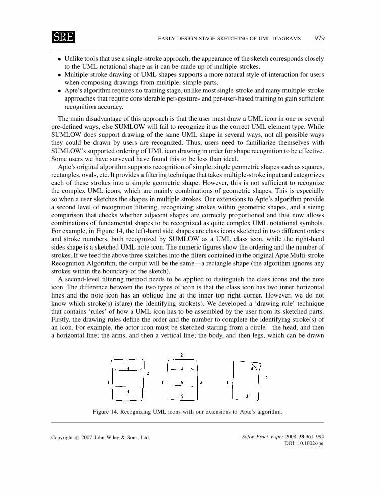
rectangles, ovals, etc. It provides a filtering technique that takes multiple-stroke input and categorizeseach of these strokes into a simple geometric shape. However, this is not sufficient to recognizethe complex UML icons, which are mainly combinations of geometric shapes. This is especiallyso when a user sketches the shapes in multiple strokes. Our extensions to Apte’s algorithm providea second level of recognition filtering, recognizing strokes within geometric shapes, and a sizingcomparison that checks whether adjacent shapes are correctly proportioned and that now allowscombinations of fundamental shapes to be recognized as quite complex UML notational symbols.For example, in Figure 14, the left-hand side shapes are class icons sketched in two different ordersand stroke numbers, both recognized by SUMLOW as a UML class icon, while the right-handsides shape is a sketched UML note icon. The numeric figures show the ordering and the number ofstrokes. If we feed the above three sketches into the filters contained in the original ApteMulti-strokeRecognition Algorithm, the output will be the same—a rectangle shape (the algorithm ignores anystrokes within the boundary of the sketch).A second-level filtering method needs to be applied to distinguish the class icons and the note
icon. The difference between the two types of icon is that the class icon has two inner horizontallines and the note icon has an oblique line at the inner top right corner. However, we do notknow which stroke(s) is(are) the identifying stroke(s). We developed a ‘drawing rule’ techniquethat contains ‘rules’ of how a UML icon has to be assembled by the user from its sketched parts.Firstly, the drawing rules define the order and the number to complete the identifying stroke(s) ofan icon. For example, the actor icon must be sketched starting from a circle—the head, and thena horizontal line; the arms, and then a vertical line; the body, and then legs, which can be drawn
Figure 14. Recognizing UML icons with our extensions to Apte’s algorithm.
Copyright q 2007 John Wiley & Sons, Ltd. Softw. Pract. Exper. 2008; 38:961–994DOI: 10.1002/spe
980 Q. CHEN, J. GRUNDY AND J. HOSKING
Figure 15. Recognized (a, c) and unrecognized (b, d) sketches in SUMLOW.
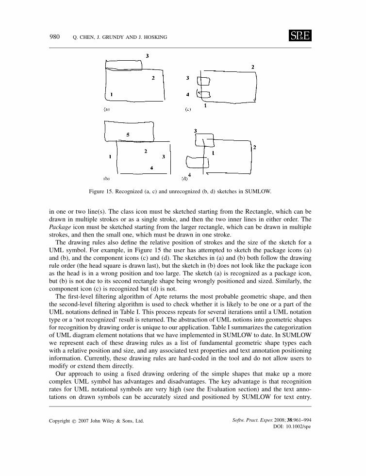
in one or two line(s). The class icon must be sketched starting from the Rectangle, which can bedrawn in multiple strokes or as a single stroke, and then the two inner lines in either order. ThePackage icon must be sketched starting from the larger rectangle, which can be drawn in multiplestrokes, and then the small one, which must be drawn in one stroke.The drawing rules also define the relative position of strokes and the size of the sketch for a
UML symbol. For example, in Figure 15 the user has attempted to sketch the package icons (a)and (b), and the component icons (c) and (d). The sketches in (a) and (b) both follow the drawingrule order (the head square is drawn last), but the sketch in (b) does not look like the package iconas the head is in a wrong position and too large. The sketch (a) is recognized as a package icon,but (b) is not due to its second rectangle shape being wrongly positioned and sized. Similarly, thecomponent icon (c) is recognized but (d) is not.The first-level filtering algorithm of Apte returns the most probable geometric shape, and then
the second-level filtering algorithm is used to check whether it is likely to be one or a part of theUML notations defined in Table I. This process repeats for several iterations until a UML notationtype or a ‘not recognized’ result is returned. The abstraction of UML notions into geometric shapesfor recognition by drawing order is unique to our application. Table I summarizes the categorizationof UML diagram element notations that we have implemented in SUMLOW to date. In SUMLOWwe represent each of these drawing rules as a list of fundamental geometric shape types eachwith a relative position and size, and any associated text properties and text annotation positioninginformation. Currently, these drawing rules are hard-coded in the tool and do not allow users tomodify or extend them directly.Our approach to using a fixed drawing ordering of the simple shapes that make up a more
complex UML symbol has advantages and disadvantages. The key advantage is that recognitionrates for UML notational symbols are very high (see the Evaluation section) and the text anno-tations on drawn symbols can be accurately sized and positioned by SUMLOW for text entry.
Copyright q 2007 John Wiley & Sons, Ltd. Softw. Pract. Exper. 2008; 38:961–994DOI: 10.1002/spe
EARLY DESIGN-STAGE SKETCHING OF UML DIAGRAMS 981
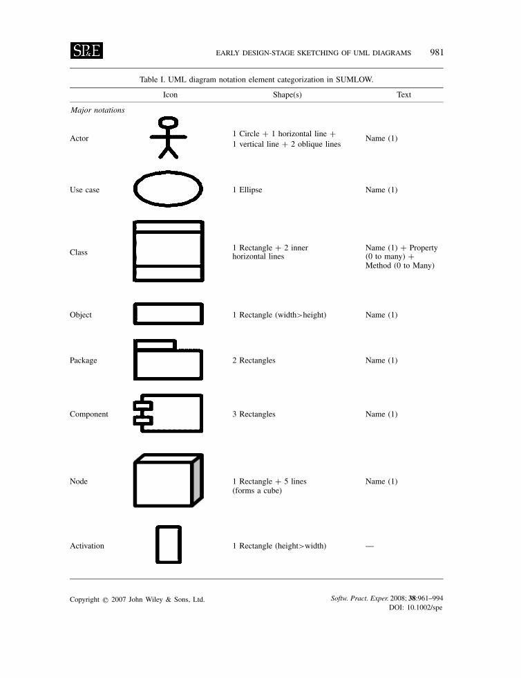
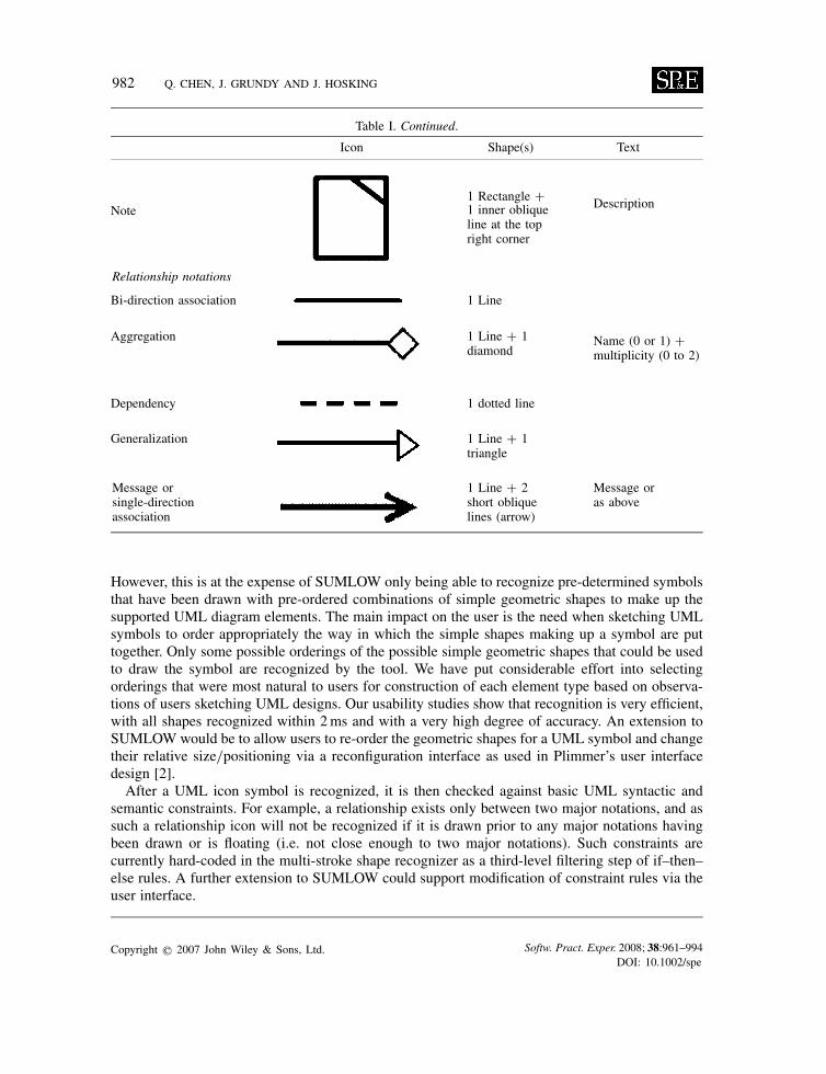
Table I. UML diagram notation element categorization in SUMLOW.
Icon Shape(s) Text
Major notations
Actor 1 Circle + 1 horizontal line + Name (1)1 vertical line + 2 oblique lines
Use case 1 Ellipse Name (1)
Class 1 Rectangle + 2 inner Name (1) + Propertyhorizontal lines (0 to many) +
Method (0 to Many)
Object 1 Rectangle (width>height) Name (1)
Package 2 Rectangles Name (1)
Component 3 Rectangles Name (1)
Node 1 Rectangle + 5 lines(forms a cube)
Name (1)
Activation 1 Rectangle (height>width) —
Copyright q 2007 John Wiley & Sons, Ltd. Softw. Pract. Exper. 2008; 38:961–994DOI: 10.1002/spe
982 Q. CHEN, J. GRUNDY AND J. HOSKING
Table I. Continued.
Icon Shape(s) Text
Note1 Rectangle + Description1 inner obliqueline at the topright corner
Relationship notations
Bi-direction association 1 Line
Name (0 or 1) +multiplicity (0 to 2)
Aggregation 1 Line + 1diamond
Dependency 1 dotted line
Generalization 1 Line + 1triangle
Message orsingle-directionassociation
1 Line + 2short obliquelines (arrow)
Message oras above
However, this is at the expense of SUMLOW only being able to recognize pre-determined symbolsthat have been drawn with pre-ordered combinations of simple geometric shapes to make up thesupported UML diagram elements. The main impact on the user is the need when sketching UMLsymbols to order appropriately the way in which the simple shapes making up a symbol are puttogether. Only some possible orderings of the possible simple geometric shapes that could be usedto draw the symbol are recognized by the tool. We have put considerable effort into selectingorderings that were most natural to users for construction of each element type based on observa-tions of users sketching UML designs. Our usability studies show that recognition is very efficient,with all shapes recognized within 2ms and with a very high degree of accuracy. An extension toSUMLOW would be to allow users to re-order the geometric shapes for a UML symbol and changetheir relative size/positioning via a reconfiguration interface as used in Plimmer’s user interfacedesign [2].After a UML icon symbol is recognized, it is then checked against basic UML syntactic and
semantic constraints. For example, a relationship exists only between two major notations, and assuch a relationship icon will not be recognized if it is drawn prior to any major notations havingbeen drawn or is floating (i.e. not close enough to two major notations). Such constraints arecurrently hard-coded in the multi-stroke shape recognizer as a third-level filtering step of if–then–else rules. A further extension to SUMLOW could support modification of constraint rules via theuser interface.
Copyright q 2007 John Wiley & Sons, Ltd. Softw. Pract. Exper. 2008; 38:961–994DOI: 10.1002/spe
EARLY DESIGN-STAGE SKETCHING OF UML DIAGRAMS 983
Single-stroke recognition for text
The multi-stroke algorithm that we used for UML diagram element recognition is unsuitable for textrecognition as users have too much variation in their writing styles. We chose to use the well-knownRubine’s single-stroke algorithm in SUMLOW for text recognition [22]. In Rubine’s algorithm, agesture is an array g of P time-stamped sample points:
gp =(xp, yp, tp), 0<= p<P
A vector of ‘features’ is extracted from the input gesture (e.g. size of enclosing rectangle, averagedistance/time between points, etc.):
f =[ f1 . . . fn]
A linear discriminator is used for pattern recognition. The recognizer is trained from a numberof examples of each gesture, typically around 10 or so. A Gesture class c has weights wci for0<= i<F , where F is the number of features.Training determines the weights wci from the set of example gestures, and a closed formula is
used instead of iterative techniques. The formula is known to produce optimal classifiers underrather strict normality assumptions on the per-class distributions of feature vectors. The Maha-lanobis distance and other methods are used for rejecting ambiguous gestures and outliers. Aninput gesture is then evaluated by a linear function over its features. The evaluations, Vc, arecalculated as
Vc=wc0+F∑
i=1wci fi , 0<=c<C
The classification of gesture g is the c which maximizes Vc.The main features of Rubine’s algorithm are that: (1) it combines statistical gesture recognition
with direct manipulation techniques; and (2) each gesture is recognized independent of its shapeand size, but has to be drawn in a single stroke. While this algorithm has been used by many otherresearchers to develop single-stroke text (and shape) recognition tools, the use of a single-strokealgorithm for sketched text is also not ideal due to a need for considerable per-user training toprovide acceptable recognition accuracy. A training module is provided to allow users to train thesystem to improve accuracy. We see this algorithm as an interim ‘convenient to implement’ solutionuntil the more robust algorithm used by Microsoft’s Tablet PC extensions has a readily accessibleapplication programming interface that can be accessed easily from SUMLOW.
Formalization of sketched content
Formalized UML diagrams are produced by converting sketched content to correspondingUML diagram elements. In order to formalize a sketched diagram, SUMLOW traverses thesketched diagram contents creating the formalized content. This process includes separatinga single SUMLOW formalized design diagram into multiple diagrams, where it containselements from incompatible UML diagram types. The sketch formalization process proceeds
Copyright q 2007 John Wiley & Sons, Ltd. Softw. Pract. Exper. 2008; 38:961–994DOI: 10.1002/spe
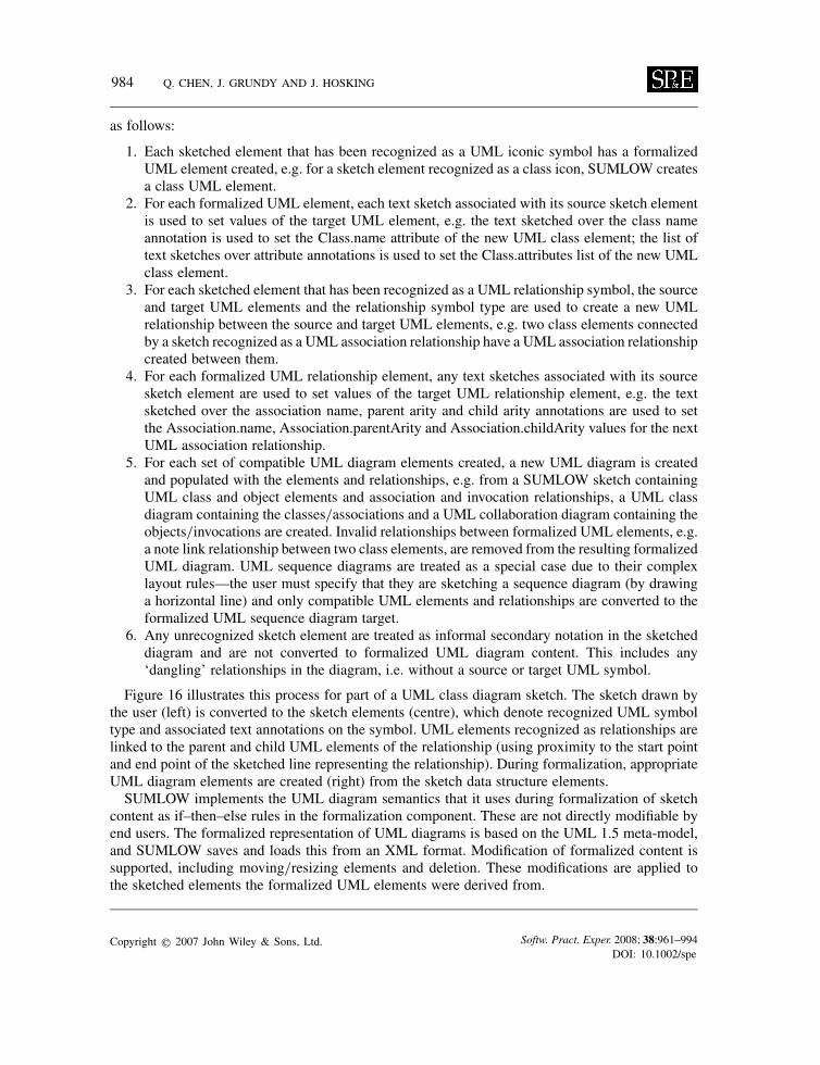
984 Q. CHEN, J. GRUNDY AND J. HOSKING
as follows:
1. Each sketched element that has been recognized as a UML iconic symbol has a formalizedUML element created, e.g. for a sketch element recognized as a class icon, SUMLOW createsa class UML element.
2. For each formalized UML element, each text sketch associated with its source sketch elementis used to set values of the target UML element, e.g. the text sketched over the class nameannotation is used to set the Class.name attribute of the new UML class element; the list oftext sketches over attribute annotations is used to set the Class.attributes list of the new UMLclass element.
3. For each sketched element that has been recognized as a UML relationship symbol, the sourceand target UML elements and the relationship symbol type are used to create a new UMLrelationship between the source and target UML elements, e.g. two class elements connectedby a sketch recognized as a UML association relationship have a UML association relationshipcreated between them.
4. For each formalized UML relationship element, any text sketches associated with its sourcesketch element are used to set values of the target UML relationship element, e.g. the textsketched over the association name, parent arity and child arity annotations are used to setthe Association.name, Association.parentArity and Association.childArity values for the nextUML association relationship.
5. For each set of compatible UML diagram elements created, a new UML diagram is createdand populated with the elements and relationships, e.g. from a SUMLOW sketch containingUML class and object elements and association and invocation relationships, a UML classdiagram containing the classes/associations and a UML collaboration diagram containing theobjects/invocations are created. Invalid relationships between formalized UML elements, e.g.a note link relationship between two class elements, are removed from the resulting formalizedUML diagram. UML sequence diagrams are treated as a special case due to their complexlayout rules—the user must specify that they are sketching a sequence diagram (by drawinga horizontal line) and only compatible UML elements and relationships are converted to theformalized UML sequence diagram target.
6. Any unrecognized sketch element are treated as informal secondary notation in the sketcheddiagram and are not converted to formalized UML diagram content. This includes any‘dangling’ relationships in the diagram, i.e. without a source or target UML symbol.
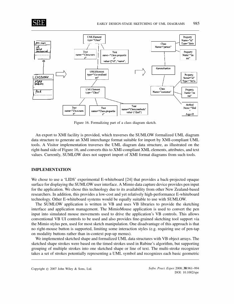
Figure 16 illustrates this process for part of a UML class diagram sketch. The sketch drawn bythe user (left) is converted to the sketch elements (centre), which denote recognized UML symboltype and associated text annotations on the symbol. UML elements recognized as relationships arelinked to the parent and child UML elements of the relationship (using proximity to the start pointand end point of the sketched line representing the relationship). During formalization, appropriateUML diagram elements are created (right) from the sketch data structure elements.SUMLOW implements the UML diagram semantics that it uses during formalization of sketch
content as if–then–else rules in the formalization component. These are not directly modifiable byend users. The formalized representation of UML diagrams is based on the UML 1.5 meta-model,and SUMLOW saves and loads this from an XML format. Modification of formalized content issupported, including moving/resizing elements and deletion. These modifications are applied tothe sketched elements the formalized UML elements were derived from.
Copyright q 2007 John Wiley & Sons, Ltd. Softw. Pract. Exper. 2008; 38:961–994DOI: 10.1002/spe
EARLY DESIGN-STAGE SKETCHING OF UML DIAGRAMS 985
Figure 16. Formalizing part of a class diagram sketch.
An export to XMI facility is provided, which traverses the SUMLOW formalized UML diagramdata structure to generate an XMI interchange format suitable for import by XMI-compliant UMLtools. A Visitor implementation traverses the UML diagram data structure, as illustrated on theright-hand side of Figure 16, and converts this to XMI-compliant XML elements, attributes, and textvalues. Currently, SUMLOW does not support import of XMI format diagrams from such tools.
IMPLEMENTATION
We chose to use a ‘LIDS’ experimental E-whiteboard [24] that provides a back-projected opaquesurface for displaying the SUMLOW user interface. AMimio data capture device provides pen inputfor the application. We chose this technology due to its availability from other New Zealand-basedresearchers. In addition, this provides a low-cost and yet relatively high-performance E-whiteboardtechnology. Other E-whiteboard systems would be equally suitable to use with SUMLOW.The SUMLOW application is written in VB and uses VB libraries to provide the sketching
interface and application management. The MimioMouse application is used to convert the peninput into simulated mouse movements used to drive the application’s VB controls. This allowsconventional VB UI controls to be used and also provides fine-grained sketching tool support viathe Mimio stylus pen, used for most sketch manipulation. One disadvantage of this approach is thatno right-mouse button is supported, limiting some interaction styles (e.g. requiring use of pen-tapon modality buttons rather than in-context pop-up menus).We implemented sketched shape and formalized UML data structures with VB object arrays. The
sketched shape strokes were based on the timed strokes used in Rubine’s algorithm, but supportinggrouping of multiple strokes into one sketched shape or line of text. The multi-stroke recognizertakes a set of strokes potentially representing a UML symbol and recognizes each basic geometric
Copyright q 2007 John Wiley & Sons, Ltd. Softw. Pract. Exper. 2008; 38:961–994DOI: 10.1002/spe
986 Q. CHEN, J. GRUNDY AND J. HOSKING
shape within the set of strokes using a version of Apte’s algorithm. A secondary filter implementedin VB applies our ‘drawing rules’ approach to identifying a most-likely match to a UML symbol.The single-stroke text recognizer uses Rubine’s algorithm and a training module to identify linesof text, each character written with a single stroke. The training module allows a user to specifyten examples of each character and this training set is saved to an MS Access database. We used adatabase rather than files as we found this easier for re-training during use of SUMLOW.We used XML files to store saved SUMLOW sketched diagram data structures and formalized
UML diagram data structures. We implemented save/load facilities using VB’s XML support viathe Microsoft XML Document Object Model (DOM) facility. A SUMLOW sketch diagram datastructure is used to create a DOM object in memory and then the DOM is written to an XMLfile. Similarly, an XML file holding a sketch diagram is loaded into a DOM and then the DOM’snodes are traversed to recreate the sketch data structure. The same approach was used to implementformalized UML diagram data structure save and load. An export facility was developed to createan XMI-compliant XML data structure in a DOM for export of a formalized UML diagram toanother XMI-compliant tool.In retrospect it would be better to use VB libraries to serialize the sketch data structure to an
XML file and vice versa. The formalized UML representation in memory should be based on theXMI standard and formalized UML diagrams written directly to an XMI-compliant file format,serving both as a persistent storage for SUMLOW and as an export format to other UML modellingtools.
DISCUSSION
We carried out two evaluations of SUMLOW. In the first evaluation we have a used the CD [37]framework to assess user interaction characteristics of sketching-based UML design compared withthe same activities carried out using a conventional whiteboard and a conventional UML designtool. We carried out a survey of several industry-based UML designers—all highly experiencedwith using a conventional whiteboard and conventional UML design tools for both early-phaseand detailed software designs with the UML—performing a sequence of collaborative, early-stagedesign tasks with SUMLOW. This evaluation provided user feedback on the tool’s suitability forUML-based software design.
Cognitive dimensions analysis
We carried out a CD assessment [37] to gauge the support of SUMLOW for exploratory UMLdesign compared with conventional whiteboards and UML CASE tools. In this assessment wemeasured different aspects of diagramming with our SUMLOW prototype and compared these withsimilar features in conventional UML design tools and a conventional whiteboard UML designactivity. Our CD-based usability results are summarized below.
• Viscosity measures a user’s ability to change content in a visual language tool. Conventionalwhiteboards are to some degree very viscous—changing already drawn content can bevery cumbersome, e.g. moving and resizing requires erasure and redrawing. Many aspectsof SUMLOW UML sketches require much less effort to change than in a conventional
Copyright q 2007 John Wiley & Sons, Ltd. Softw. Pract. Exper. 2008; 38:961–994DOI: 10.1002/spe
EARLY DESIGN-STAGE SKETCHING OF UML DIAGRAMS 987
whiteboard, e.g. redrawing over the top of a shape in order to resize it, selection and dragto move icons, etc. Similarly, these tasks compare favourably with conventional UMLCASE tools where both limitations of conventional mouse editing operations and UMLdesign constraints sometimes interfere with the user’s ability to change diagrams. Otherediting operations in SUMLOW require more effort, e.g. movement of a shape is a sequenceof change mode/select/drag vs click and drag in most mouse-based tools. In addition,many conventional tools apply layout and appearance heuristics to a design as the userbuilds it, e.g. repositioning shapes to a grid automatically. This is of course contrary tothe key idea of SUMLOW providing a sketching facility, like a conventional whiteboardinterface.
• Secondary notation measures the support for informal, user-defined notations, e.g. layout orappearance in visual language tools. In SUMLOW the user has great freedom to sketch anytype of secondary notation. This is more flexible than almost any conventional CASE tools weare aware of and in fact is similar to the infinite range of secondary notation available to usersof a conventional whiteboard. However, a consequence is that, to recognize sketched diagramelements that are primary notation, some drawing operation ordering and sub-element conven-tions must be met (the ‘drawing rules’ for our multi-stroke recognizer). This can adverselyaffect the usability of SUMLOW as it sometimes does not recognize an element and treats itas informal secondary notation. SUMLOW, unlike conventional UML tools, also allows usersto mix notational elements, which other researchers have identified as useful in early-phasesoftware design. As SUMLOW uses no automatic layout algorithm for diagrams, this allowsusers to position diagrammatic symbols as a form of secondary notation. Some conventionalUML CASE tools enforce an automatic layout algorithm which may impair early design workin particular [16].
• Provisionality measures the degree of commitment to actions or marks. Is it possible to sketchthings out when you are playing around with ideas, or when you are not sure which way toproceed? Both the conventional whiteboard and SUMLOW provide excellent provisionalitysupport, with no commitment required until sketches are completed. By contrast, conventionalUML tools require immediate commitment.
• Premature commitmentmeasures constraints on the order of doing things. SUMLOW has somedisadvantages over conventional whiteboards in that shapes must be drawn in the correct orderfor the recognition algorithm to work and some advantages in that initial layout commitmentsmay be readily modified. The allowance of ‘dangling’ relationships in SUMLOW provides anadvantage over conventional UML tools.
• Closeness of mapping measures how closely a tool’s notation matches the target domain’sconcepts in a visual language tool. A conventional whiteboard enforces absolutely noconstraint on the appearance of UML designs drawn upon it, which is both an advantage anda disadvantage. For example, it allows each user his or her own idiosyncratic shape drawing,which provides flexibility at the cost of inconsistent appearance. As we aim to support UMLmodelling with SUMLOW, all sketched diagram elements must have some degree of similarityto computer-drawn UML elements in order to be recognized both by the recognition algorithmand also by the end user. This constrains the user to a degree and resolving mis-recognitioncan adversely impact on the usability of the tool. Conventional tools do not have this problemas the user is forced to specify the exact type of element to add to a diagram by the tool’ssyntax-directed editing interface. Most conventional UML design tools enforce some UML
Copyright q 2007 John Wiley & Sons, Ltd. Softw. Pract. Exper. 2008; 38:961–994DOI: 10.1002/spe
988 Q. CHEN, J. GRUNDY AND J. HOSKING
syntax and semantics constraints during editing, and studies have shown this to be quiteproblematic for exploratory design work [16].
• Hard mental operations measures how hard the user has to work in order to understand infor-mation or instruct a visual language tool. As conventional whiteboards enforce no constraintson users, a (common) consequence may be extreme difficulty in understanding diagrams [9].Similarly, ambiguous or poorly drawn sketches in SUMLOW can cause confusion for both thetool’s shape and text recognition algorithms and its users. SUMLOW sometimes cannot recog-nize the information intended or makes mistakes and recognizes things as the wrong constructleading to mismatches between the user’s mental model and the tool’s formal model. Theability to add any UML notational element to any diagram exacerbates this as the tool cannotassume a smaller set of allowable elements as in conventional, more rigid UML tools. Thelearning curve of the text and shape sketching/recognition algorithms currently make learningto use the tool in some respects more difficult than conventional mouse- and keyboard-drivenUML CASE tools. For example, users must draw complex, multi-stroke UML element icons ina small number of allowable orders, else SUMLOW will fail to recognize them. While this hasnot proved to be overly problematic in practice, it does impose extra hard mental operationson the user, particularly on novice SUMLOW users.
• Abstraction measures the ability to specify new abstractions that extend the notation. Conven-tional whiteboards allow infinite extensibility of notations. Both SUMLOW and conventionalUML tools are quite constraining. However, SUMLOW does allow the text recognizer tobe retrained, offering some customization support, and does support an infinite variety ofsecondary annotations.
• Hidden dependencies measures the degree of hidden dependencies between information inthe same or different views in a tool. Conventional whiteboards rely totally on users explic-itly drawing dependencies or communicating them to each other via gestures and speech.In conventional UML design tools, there are dependencies between the same UML modelelements shown in multiple views by element name only, without explicit visual linkages, butoften with navigational support to mitigate the hidden dependencies. SUMLOW also representsdependencies between such UML elements internally without explicitly representing them inviews. SUMLOW has additional hidden dependencies that do not exist in conventional UMLdesign tools or whiteboards—the link between a sketch element and its recognized shape ortext. These dependencies are represented by mouse-over hints in the SUMLOW sketch viewsand formalization of a diagram uses them to explicitly represent sketch elements as computer-drawn shapes and text. The user can override a recognition attempt by SUMLOW by selectingan element and manually indicating what type it is, or redrawing over the top of it to forceupdate of its appearance and re-recognition by SUMLOW, changing the recognition hiddendependency.
• Progressive evaluationmeasures the degree of step-by-step evaluation of information supportedby a visual language tool as it is used. Conventional whiteboards do not support progressiveevaluation. Both the SUMLOW shape and text recognizers and the user-demanded formaliza-tion of designs support progressive evaluation. Shapes are recognized after the user has drawnmultiple lines and pauses, or moves to a different part of the sketching area. Text is recognizedafter the user has sketched over the top of a text annotation and moves to a different areaof the owning shape or diagram. Design views are created and modified as a sketch view ismanipulated and can be viewed at any time or simultaneously with SUMLOW sketch views.
Copyright q 2007 John Wiley & Sons, Ltd. Softw. Pract. Exper. 2008; 38:961–994DOI: 10.1002/spe
EARLY DESIGN-STAGE SKETCHING OF UML DIAGRAMS 989
User evaluation
We carried out a user evaluation of SUMLOW to assess its usability and appropriateness for earlydesign UML diagramming. The selected evaluators of SUMLOW were first given a tutorial ofhow to use the tool and a chance to try out the tool for half an hour each with the tool designerpresent and answering any questions about using the tool. They were then given two simple designtasks—one single-user and one two-user collaboration. These tasks involved diagram sketching,manipulation and revision, and formalization of design sketches. The evaluators were then askedto complete the questionnaire based on their experiences using SUMLOW for these tasks. Elevenevaluators took part: five postgraduate computer science students and six analysts/programmers.Each of the industry-based analysts/programmers had between 2 and 5 years (average 3.6) ofworking experience in software design.The closed and open questions in our survey concentrated on:
1. feedback on SUMLOW’s utility for early-design UML diagram production; and2. users’ assessment of the accuracy of the shape recognition component.
Key survey findings are summarized as follows:
• Overall nearly all of the evaluators found that SUMLOW was easy to learn and use. Almostall evaluators found SUMLOW’s pen manipulation of diagrams to be very time efficient,especially for the early-stage UML design tasks they carried out. Less than 25% of users haddifficulty in learning to use the moving and resizing operations of SUMLOW.
• The example design review and design revision tasks—not early-stage design tasks—thatwe asked evaluators to carry out were thought to be less suitable for SUMLOW. Ideally,these tasks require more UML diagram syntax and semantics constraints to be checked whilemanipulations are carried out on the diagrams. However, all evaluators could perform theserevision tasks with SUMLOW sketches and over 70% felt SUMLOW sketch views provideda better environment to discuss and collaboratively revise designs than conventional UMLdesign tools.
• All evaluators felt that good feedback is provided to users of pen manipulations of diagramcontent both while it is in progress and when it is finished. This includes active feedback tousers of changes being made to diagram content and results of manipulations and the shapeand text recognition engine running results.
• Almost all users felt that the SUMLOW user interface provides a good design for early-stage UML design work. However, nearly half of the evaluators found the SUMLOW modalinterface to be difficult to use initially. However, as this approach is close to that used by mostconventional UML CASE tools, nearly all evaluators found it acceptable after some experiencewith it. All evaluators noted that the SUMLOW interface provides many features not supportedon a whiteboard. Some make diagramming easier, e.g. automatic resizing and preservation ofcontent, but others are less intuitive, e.g. having to change the drawing mode to select anddelete items.
• Several users suggested more use of gesture-based operations in SUMLOW, e.g. two linesdrawn quickly through a shape or text to delete it instead of selection then deletion gesture.Currently, gestures are used to initiate and actionmoving, deleting, and front/back repositioningof shapes and draw-over for resize, which was found by users to be intuitive and helpful.
Copyright q 2007 John Wiley & Sons, Ltd. Softw. Pract. Exper. 2008; 38:961–994DOI: 10.1002/spe
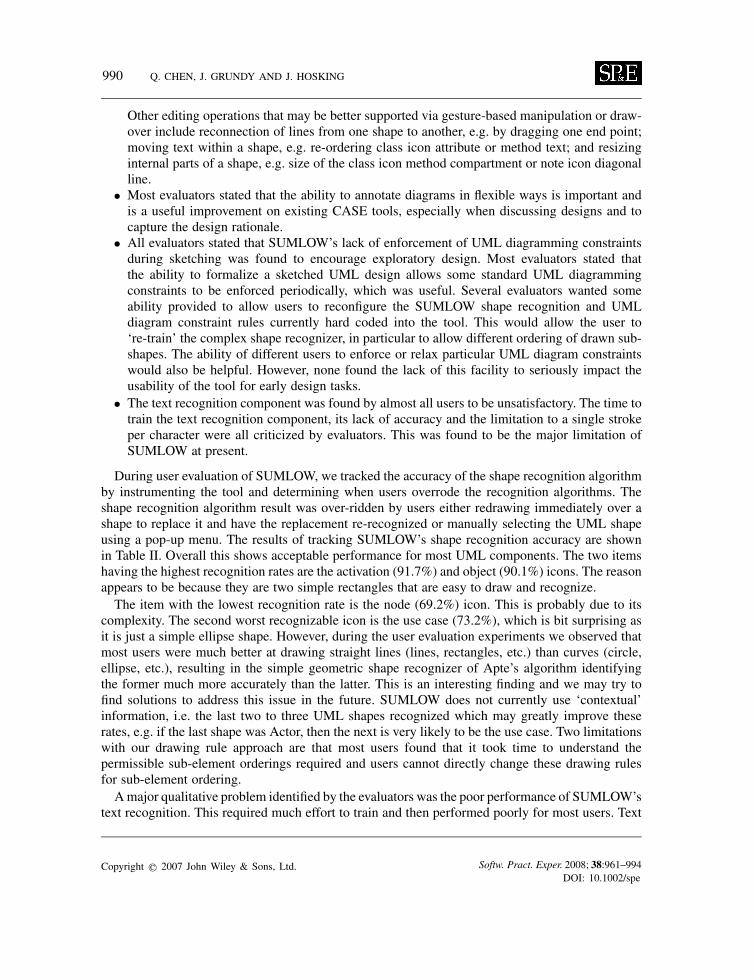
990 Q. CHEN, J. GRUNDY AND J. HOSKING
Other editing operations that may be better supported via gesture-based manipulation or draw-over include reconnection of lines from one shape to another, e.g. by dragging one end point;moving text within a shape, e.g. re-ordering class icon attribute or method text; and resizinginternal parts of a shape, e.g. size of the class icon method compartment or note icon diagonalline.
• Most evaluators stated that the ability to annotate diagrams in flexible ways is important andis a useful improvement on existing CASE tools, especially when discussing designs and tocapture the design rationale.
• All evaluators stated that SUMLOW’s lack of enforcement of UML diagramming constraintsduring sketching was found to encourage exploratory design. Most evaluators stated thatthe ability to formalize a sketched UML design allows some standard UML diagrammingconstraints to be enforced periodically, which was useful. Several evaluators wanted someability provided to allow users to reconfigure the SUMLOW shape recognition and UMLdiagram constraint rules currently hard coded into the tool. This would allow the user to‘re-train’ the complex shape recognizer, in particular to allow different ordering of drawn sub-shapes. The ability of different users to enforce or relax particular UML diagram constraintswould also be helpful. However, none found the lack of this facility to seriously impact theusability of the tool for early design tasks.
• The text recognition component was found by almost all users to be unsatisfactory. The time totrain the text recognition component, its lack of accuracy and the limitation to a single strokeper character were all criticized by evaluators. This was found to be the major limitation ofSUMLOW at present.
During user evaluation of SUMLOW, we tracked the accuracy of the shape recognition algorithmby instrumenting the tool and determining when users overrode the recognition algorithms. Theshape recognition algorithm result was over-ridden by users either redrawing immediately over ashape to replace it and have the replacement re-recognized or manually selecting the UML shapeusing a pop-up menu. The results of tracking SUMLOW’s shape recognition accuracy are shownin Table II. Overall this shows acceptable performance for most UML components. The two itemshaving the highest recognition rates are the activation (91.7%) and object (90.1%) icons. The reasonappears to be because they are two simple rectangles that are easy to draw and recognize.The item with the lowest recognition rate is the node (69.2%) icon. This is probably due to its
complexity. The second worst recognizable icon is the use case (73.2%), which is bit surprising asit is just a simple ellipse shape. However, during the user evaluation experiments we observed thatmost users were much better at drawing straight lines (lines, rectangles, etc.) than curves (circle,ellipse, etc.), resulting in the simple geometric shape recognizer of Apte’s algorithm identifyingthe former much more accurately than the latter. This is an interesting finding and we may try tofind solutions to address this issue in the future. SUMLOW does not currently use ‘contextual’information, i.e. the last two to three UML shapes recognized which may greatly improve theserates, e.g. if the last shape was Actor, then the next is very likely to be the use case. Two limitationswith our drawing rule approach are that most users found that it took time to understand thepermissible sub-element orderings required and users cannot directly change these drawing rulesfor sub-element ordering.Amajor qualitative problem identified by the evaluators was the poor performance of SUMLOW’s
text recognition. This required much effort to train and then performed poorly for most users. Text
Copyright q 2007 John Wiley & Sons, Ltd. Softw. Pract. Exper. 2008; 38:961–994DOI: 10.1002/spe
EARLY DESIGN-STAGE SKETCHING OF UML DIAGRAMS 991
Table II. Accuracy of SUMLOW shape recognition.
Constructs Recognition rate (%)
Actor 89.3Use case 73.2Class 88.5Object 90.1Component 83.0Node 69.2Note 84.3Activation 91.7Package 86.1Association 89.6Dependency 87.3Generalization 79.0Aggregation 80.2Message 88.9Average 84.3
recognition can be overridden by either redrawing the text or using an on-screen pop-up keyboard.Most evaluators resorted to using the pop-up on-screen keyboard in the end.
Strengths and limitations of SUMLOW
From our evaluations of our SUMLOW E-whiteboard UML design tool, we can conclude that itprovides an efficient and effective sketching-based user interface on a large-screen E-whiteboard.Both the design sketch elements and text are constructed and manipulated using pen-based input.The tool provides freedom from heavily enforced UML modelling constraints and supports bothflexible shape sketching and a flexible diagram and shape annotation facility. A pen-based diagrammanipulation approach is used, which enhances conventional whiteboard drawing manipulationfacilities. The large display surface of the E-whiteboard hosting SUMLOW supports face-to-facecollaborative design and multi-user manipulation of the sketched designs via turn taking. Userscan move between different UML modelling views, can use any UML modelling element in anyview, and can formalize their designs periodically into computer-drawn UML diagrams. Theseformalized diagrams can also be manipulated using pen-based input within SUMLOW. Users canexport formalized design diagrams to conventional UML CASE tools for further refinement anduse. In conclusion, these facilities within the environment encourage exploratory and collaborativeUML-based early-phase software design. SUMLOW differs from conventional UML tools in itsuse of sketching-based diagram construction and manipulation. It differs from other sketching-based UML design tools in its preservation of hand-drawn sketches and emphasis on gesture-basedmanipulation of these hand-drawn, whiteboard-like sketches.Disadvantages of our present SUMLOW prototype include recognition problems with some
shape elements, but particularly with the single-stroke text recognition algorithm. Users must drawcomplex UML model shapes sub-element by sub-element in a limited range of orders so thatthe multi-stroke recognition algorithm correctly recognizes them. This makes the learning curvefor some shape modelling difficult, but is a trade-off that is difficult to avoid when providing
Copyright q 2007 John Wiley & Sons, Ltd. Softw. Pract. Exper. 2008; 38:961–994DOI: 10.1002/spe
992 Q. CHEN, J. GRUNDY AND J. HOSKING
both generous secondary notation capabilities and good recognition of primary notation. Currently,SUMLOW does not use the most recently recognized or located UML symbols to help the recogni-tion of the next sketched UML symbol. Some diagram manipulation functions could be enhancedto make it easier to specify what user operation is required. Many users felt that this could beimproved by employing hot-spots on shapes or pop-up menus instead of modal buttons whichdistract users and slow their sketching down. Gesture-based instructions could also be used. One-directional translation of sketch to formalized UML model design is a limitation as it means userscannot import a UML diagram from a CASE tool and then use the sketching interface to reviewand modify it. There is no current support for distributed sketching-based design with multipleE-whiteboards, limiting SUMLOW’s current use to a single E-whiteboard deployment.
Future work
A number of enhancements can bemade to SUMLOW to improve its usability, particularly improvedtext recognition and shape recognition facilities. We are investigating using multi-stroke recognitionsystems that are trainable by end users for both shape and text recognition support [30]. Thesealgorithms have been shown to be much more accurate than those currently employed in SUMLOW,with the added benefit of per-user customization support. In addition, wewish to enhance recognitionof shapes to take into account recently recognized and closely located symbols. We believe thiswill further enhance the recognition system. Currently, we have only investigated the use of asingle E-whiteboard by one or more designers. We plan to include a generalization of our sketchingand E-whiteboard presentation support into a meta-CASE tool we are developing, making it mucheasier to ‘E-whiteboard’ enable a wide range of design tools. This has the added advantage thatthe meta-tool specifies the visual language meta-models and constraints in a user-customizable andextensible form. These can be used during the recognition and formalization processes rather thanthe hard-coded model and rules as done in our current SUMLOW prototype.We would like to explore distributed, same-time different-place collaboration support utilizing
multiple E-whiteboards. This will allow multiple users at a distance to interact with SUMLOWusing their own E-whiteboard. Additional collaboration support facilities would be needed, e.g.group awareness support and diagram element access controls. We are interested in deploying thetool on tablet PC environments to exploit their built-in pen-based input facilities and also to exploremulti-user design via distributed tablet PCs as well as multiple E-whiteboards. Support for a bi-directional sketch to a formal UML model and a formal model to sketch transformation wouldenable SUMLOW to be used as a UML design review tool. The latter will support import of modelsfrom existing UML design tools and support sketch-based manipulation and annotation of theseUML models for design review and re-engineering tasks.
CONCLUSIONS
We have described SUMLOW, a sketching-based UML design tool for E-whiteboard technology.SUMLOW supports early-phase UML design using sketching-based input UML software designelements. These sketched elements are recognized proactively by SUMLOW, but with hand-drawnshapes preserved. Users can collaboratively design with SUMLOW using a large E-whiteboard,can flexibly annotate sketched designs with their own secondary notation, and gesture-based
Copyright q 2007 John Wiley & Sons, Ltd. Softw. Pract. Exper. 2008; 38:961–994DOI: 10.1002/spe
EARLY DESIGN-STAGE SKETCHING OF UML DIAGRAMS 993
manipulation of design sketches and single-stroke text recognition are supported. SUMLOW allowsusers to flexibly mix UML design constructs, and users may on demand have SUMLOW formalizetheir design sketches and export them to existing UML CASE tools. A key novelty of our approachis the preservation of sketched diagram content and co-existing, consistent sketched diagram andformalized diagram views. We have carried out two evaluations of SUMLOW, one using the CDframework and the other using target end users. These evaluations have indicated that our approachis promising for the target goal of a better-supporting exploratory, early-stage collaborative UMLdesign.
REFERENCES
1. Smart Technologies Inc. SMART Board. www.smarttech.com [18 September 2007].2. Plimmer B, Apperley M. Computer-aided sketching to capture preliminary design. In Proceedings of the Third Australasian
Conference on User Interfaces—Volume 7, Melbourne, Victoria, Australia (ACM International Conference ProceedingSeries, vol. 20). Australian Computer Society: Darlinghurst, Australia, 2002; 9–12.
3. Berque D, Johnson DK, Jovanovic L. Teaching theory of computation using pen-based computers and an electronicwhiteboard. ACM SIGCSE Bulletin, vol. 33(3). ACM Press: New York, 2001; 169–172.
4. Lank E, Thorley J, Chen S, Blostein D. On-line recognition of UML diagrams. Proceedings of the Sixth InternationalConference on Document Analysis and Recognition. IEEE CS Press: Silver Spring, MD, 2001; 356–360.
5. Fowler M, Scott K. UML Distilled: A Brief Guide to the Standard Object Modeling Language (2nd edn). Addison-Wesley:Reading, MA, 1999.
6. UMLTM Resource Page, OMG (Object Management Group). http://www.uml.org/ [18 September 2007].7. Quatrani T. Visual Modeling with Rational Rose 2002 and UML (3rd edn). Addison-Wesley: Reading, MA, 2002.8. Robbins J, Redmiles D. Cognitive support, UML adherence, and XMI interchange in Argo/UML. Information and
Software Technology, 2000.9. Iivari J. Why are CASE tools not used? Communications of the ACM 1996; 39(10):94–103.
10. Black A. Visible planning on paper and on screen: The impact of working medium on decision-making by novicegraphic designers. Behaviour and Information Technology 1990; 9(4):283–296.
11. Mackay D, Biddle R, Noble J. A lightweight web based case tool for UML class diagrams. Proceedings of the 4thAustralasian User Interface Conference, Adelaide, South Australia, 2003 (Conferences in Research and Practice inInformation Technology, vol. 18). Australian Computer Society: Adelaide, South Australia, 2003.
12. Gray J, Liu A, Scott L. Issues in software engineering tool construction. Information and Software Technology 2000;42(2):73–77.
13. Damm CH, Hansen KM, Thomsen M. Tool support for cooperative object-oriented design: Gesture based modeling onan electronic whiteboard. Proceedings of the CHI 2000 on Human Factors in Computer Systems: The Future is Here.ACM Press: New York, 2000; 518–525.
14. Landay JA. SILK: Sketching interfaces like krazy. Proceedings of CHI’96 on Human Factors in Computer Systems:Common Ground. ACM Press: New York, 1996; 518–525.
15. Goel V. Sketches of Thought. The MIT Press: Cambridge, MA, 1995.16. Brooks A, Scott L. Constraints in CASE Tools: Results from curiosity driven research. Proceedings of the 2001 Australian
Software Engineering Conference, Canberra, Australia, 26–28 August 2001. IEEE CS Press: Silver Spring, MD, 2001;285–296.
17. Grief I, Seliger A, Weihl W. A case study of CES: A distributed collaborative editing system implemented in Argus.IEEE Transactions on Software Engineering 1992; 18(9):827–839.
18. Grundy JC, Hosking JG. Engineering plug-in software components to support collaborative work. Software—Practiceand Experience 2002; 32(10):983–1013.
19. Shuckman C, Kirchner L, Schummer J, Haake JM. Designing object-oriented synchronous groupware with COAST.Proceedings of the ACM Conference on Computer Supported Cooperative Work. ACM Press: New York, 1996; 21–29.
20. Wong YY. Rough and ready prototypes: Lessons from graphic design. Human Factors in Computing Systems CHI ’92,Monterey, 1992.
21. Goldschmidt G. Serial sketching: Visual problem solving in design, the backtalk of self-generated sketches. Cyberneticsand Systems 1992; 23:191–219.
22. Rubine D. Specifying gesture by examples. Proceedings of the 18th Annual Conference (1991) on Computer Graphicsand Interactive Techniques. ACM Press: New York, 1991; 329–337.
23. Lin J, Newman MW, Hong JI, Landay JA. Denim: Finding a tighter fit between tools and practice for web design.Proceedings of CHI’2000. ACM Press: New York, 2000; 510–517.
Copyright q 2007 John Wiley & Sons, Ltd. Softw. Pract. Exper. 2008; 38:961–994DOI: 10.1002/spe
994 Q. CHEN, J. GRUNDY AND J. HOSKING
24. Apperley M, Dahlberg B, Jefferies A, Paine L, Phillips M, Rogers B. Lightweight capture of presentations for review.Proceedings of IHM-HCI, Lille, France. ACM Press: New York, 2002.
25. Myers BA. The Amulet environment: New models for effective user interface software development. IEEE Transactionson Software Engineering 1997; 23(6):347–365.
26. Voida S, Mynatt ED, MacIntyre B, Corso GM. Integrating virtual and physical context to support knowledge workers.IEEE Pervasive Computing 2002; 1(3):73–79.
27. Ratzer AV, Hansen KM. Ideogramic: flexibility and formality in collaborative diagramming. Proceedings of the SecondNordic Conference on Human-Computer Interaction, NordiCHI’02, Aarhus, Denmark, 19–23 October 2002, vol 31.ACM Press: New York, NY, 291–292. DOI: http://doi.acm.org/10.1145/572020.572069.
28. Hse H, Newton AR. Sketched symbol recognition using Zernike moments. Proceedings of the 2004 InternationalConference on Pattern Recognition, Cambridge, U.K., August 2004; 367–370.
29. Alvarado C, Davis R. SketchREAD: A multi-domain sketch recognition engine. Proceedings of the 2004 ACM Symposiumon User Interface Software and Technology, ACM Press: New York, 2004.
30. Hse H, Shilman M, Newton AR. Robust sketched symbol fragmentation using templates. Proceedings of the 2004International Conference on Intelligent User Interfaces, Funchal, Portugal, January 2004; 156–160.
31. Sezgin TM, Davis R. HMM-based efficient sketch recognition. Proceedings of the 2005 International Conference onIntelligent User Interfaces, New York, 9–12 January 2005.
32. Donaldson A, Williamson A. Pen-based input of UML activity diagrams for business process modelling. The HCI 2005Workshop on Improving and Assessing Pen-based Input Techniques, Edinburgh, Scotland, Monday 5 September 2005.
33. Hammond T, Davis R. Tahuti: A geometrical sketch recognition system for UML class diagrams. Proceedings of the2002 AAAI Spring Symposium on Sketch Understanding, Stanford, CA, 25–27 March 2002; 59–68.
34. Chen Q, Grundy JC, Hosking JG. An E-whiteboard application to support early design-stage sketching of UML diagrams.Proceedings of the 2003 IEEE Symposium on Human Centric Computing Languages and Environments, Auckland,New Zealand, October 2003. IEEE: New York, 2003; 219–226.
35. Mimio® home page: from http://www.mimio.com [26 March 2003].36. Apte A, Vo V, Kimura TD. Recognizing multistroke geometric shapes: An experimental evaluation. Proceedings of the
6th Annual ACM Symposium on User Interface Software and Technology, ACM Press: New York, 1993; 121–128.37. Green TRG, Petre M. Usability analysis of visual programming environments: A ‘cognitive dimensions’ framework.
Journal of Visual Languages and Computing 1996; 7:131–174.
Copyright q 2007 John Wiley & Sons, Ltd. Softw. Pract. Exper. 2008; 38:961–994DOI: 10.1002/spe