Embed Size (px)
Citation preview

JNPS-O826C
~ J1~ ft ~ :a:
Product Specification
APRV~~~ (Y21 ~j£
CHKD. Zsh~ 'fIi.9 J",,'k
PRPD. ?: < ~~ I U~.t ld;y
SUMITOMO 3M LI MITED
ELECTRONIC SOLUTIONS DIVISIONTECHNICAL DEPARTMENT
JNPS-O826 c
1 FUNCTION
This connector is one of board mount connectors designed for IDC (Insulation Displacement
Connector) connection with 1.27mm pitch flat cable. This connector has 2 rows ofplural U-elements attop side and 2 rows of contact tails on 2.54mmx2.54mm ( .1 !lx .1!1) grid at bottom side. Then, thisconnector has the function of electrical connection between cable and PC board.
2 COMPATIBLE OBJECTS
2- WIRE ACCOMODATION
28 A WG Stranded *corresponding with UL Style 2651
2-2 COMPATIBLE BOARD
Thickness: 1.6mm :t O.2mm
Through hole diameter: «I> O.8mm :t O.1mm, 2.54mmx2.54mm grid* Refer to the drawing 4U-OO10-0919-0.
3. RELA TED SPECIFICA TION DRA WINGS
See the drawings described in JNPD-O826.
4 RELA TED TEST STANDARDS
MIL-Sm-202JEIDA-38-1984ns C 0050JNTM-0039, JNTM-0040* JNTM: Test Method Standard of Sumitomo 3M for Electronic and Electrical Component Parts
5 APPLICA TION
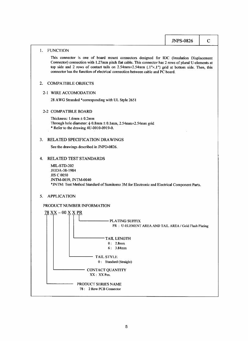
PRODUCT NUMBER INFORMATION
78 XX -00 ~: --PR
TpLATINGSUFFIXPR : U-ELEMENT AREA AND TAIL AREA / Gold Flash Plating
TAIL LENGTH0: 2.8mm6 : 3.84mm
TAIL STYLE
O : Standard (Straight)
CONTACT QUANTITYXX : xx Pos.
PRODUCT SERIES NAME
78 : 2 Row PCB Connector
5
JNPS-O826 c
6 QUALITY PERFORMANCE
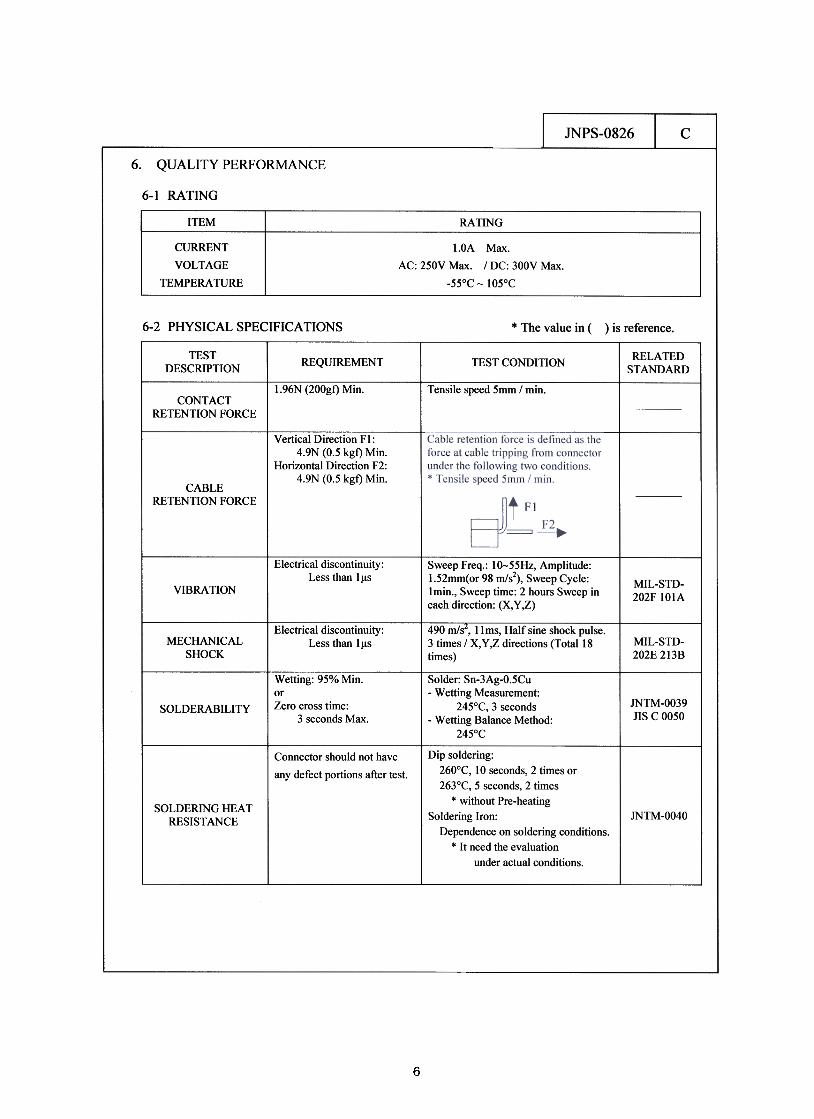
6-1 RATING
6-2 PHYSICAL SPECIFICATIONS * The value in () is reference
TESTDESCRIPTION
RELATEDSTANDARDREQUIREMENT TESTCONDmON
1.96N (200gf) Min.--Tensile speed Smm I min
CONTACT
RETENnON FORCE
Vertical Direction Fl:4.9N (0.5 kgf) Min.
Horizontal Direction F2:4.9N (0.5 kgf) Min.
CABLE
RETENTION FORCE
Electrical discontinuityLess than l~s
Sweep Freq.: lo-55Hz, Amplitude:1.52mm(or 98 mls1, Sweep Cycle:Imin., Sweep time: 2 hours Sweep ineach direction: (X, y ,Z)
MIL-STD-202F lOlA
VIBRAnON
490 m/s", 11 ms, Half sine shock pulse.3 times / X, Y,z directions (Total 18times)
Electrical discontinuityLess than Il1sMECHANICAL
SHOCKMIL-STD-202E 2138
Solder: Sn-3Ag-O.5Cu-Wetting Measurement:
245°C, 3 seconds-Wetting Balance Method
245°C
JNTM-OO39JISC0050
Wetting: 95% Min.orZero cross time:
3 seconds MaxSOLDERABILITY
Connector should not have
any defect portions after test.
SOLDERING HEATRESISTANCE JNTM-OO40
Dip soldering:260°C, 10 seconds, 2 times or263°C, 5 seconds, 2 times
* without Pre-heating
Soldering Iron:Dependence on soldering conditions
* It need the evaluation
under actual conditions.
6

JNPS-O826 c
6-3 ELECTRICAL SPECIFICATIONS
TESTDESCRIPTION
RELATEDSTANDARDREQUIREMENT TEST CONDlmON
Impressed voltage is AC IOOOV rms.between adjacent two contacts for oneminute.
No appearance of arcingand break down.Leak current: lmA Max.
DIELECTRICWITHSTANDING
VOLTAGE
IOOOM.Q Mill. Impressed voltage is DC SOOV betweenadjacent two contacts for one minute.INSULATION
RESIDENSE
-Initial/
25 mQ Max.-Change of contactresistance afterenvironmental tests i
20 mQ Max.
Contact resistance is measuredat Short Circuit.
Current: 1.5mAOpen Circuit Voltage: 20mVby 4 terminal method.* Measurement values include
the resistance of contact pinsas conductive material
CONTACTRESISTANCE See Table I
* Refer to Table I regarding the conditions
of each environmental test.
Table ENVIROMENTAL TEST
ITEM TEST CONDITION RELATED STANDARD
MOISTURE -10- 65°C, Relative Humidity 95% /10 cycles MlL-Sm-202FIO6D
SALT SPRAY NaCI 5% solution, 35°C / 48 hours MIL-STD-202FIOlD
THERMAL SHOCK -55°C~25°C~85°C~25°C /5 cycles MIL-Sm-202FIO7G
HUMIDITY
(STEADY STATE)40°C, Relative Humidity 95% / 96 hours MIL-STD-202FI038
THERMAL LIFE Steady Current: Current Rating x 110%, 85°C / 1000 hours
H2S GAS 3 :t 1 ppm, 40°C, Relative Humidity 70 -80% / 96 hours JEIDA-38-1984
7. PLA TING SPEC INDICA TION ON CONNECTOR
The first letter, in stamped 3 letters on the connector body for lot numbering, identified the following
plating specs.
~ xx: PR plating* XX: two alphabet letters
'7

JNPS-O826 c
8. p ACKAGE & IDENTIFICA TION
These products are packed with plastic tray and carton box for transit.Carton box are identified by part number, quantity, maker name and lot number.
9. STORAGE
This products shall be stored in a room, ambient temperature 5 -35°C, and ambient humidity
40- 70%.
8