Embed Size (px)
Citation preview
University of Illinois at Urbana-Champaign
Air Conditioning and Refrigeration Center A National Science Foundation/University Cooperative Research Center
Suitability of Polymer Heat Exchangers for Air Conditioning Applications
T. Malik and C. W. Bullard
ACRC TR-237 March 2005
For additional information:
Air Conditioning and Refrigeration Center University of Illinois Mechanical & Industrial Engineering Dept. 1206 West Green Street Urbana, IL 61801 Prepared as part of ACRC Project #148 Exploring Component and System Design Tradeoffs (217) 333-3115 C. W. Bullard, Principal Investigator
The Air Conditioning and Refrigeration Center was founded in 1988 with a grant from the estate of Richard W. Kritzer, the founder of Peerless of America Inc. A State of Illinois Technology Challenge Grant helped build the laboratory facilities. The ACRC receives continuing support from the Richard W. Kritzer Endowment and the National Science Foundation. The following organizations have also become sponsors of the Center. Arçelik A. S. Behr GmbH and Co. Carrier Corporation Cerro Flow Products, Inc. Copeland Corporation Daikin Industries, Ltd. Danfoss A/S Delphi Thermal and Interior Embraco S. A. Ford Motor Company Fujitsu General Limited General Motors Corporation Hill PHOENIX Hydro Aluminum Adrian, Inc. Ingersoll-Rand/Climate Control Lennox International, Inc. LG Electronics, Inc. Manitowoc Ice, Inc. Modine Manufacturing Co. Novelis Global Technology Centre Parker Hannifin Corporation Peerless of America, Inc. Samsung Electronics Co., Ltd. Sanden Corporation Sanyo Electric Co., Ltd. Tecumseh Products Company Trane Visteon Automotive Systems Wieland-Werke, AG Wolverine Tube, Inc. For additional information: Air Conditioning & Refrigeration Center Mechanical & Industrial Engineering Dept. University of Illinois 1206 West Green Street Urbana, IL 61801 217 333 3115
1
Abstract The project compares the non-metallic/polymer heat exchangers to the current technology in metallic heat
exchangers. A review of state of the art of polymer heat exchangers is presented and technological problems are
identified. Simulation models were developed and used to explore the thermal-hydraulic, packaging and weight
tradeoffs associated with polymer heat exchangers. Finally, the results are used to provide essential background for
deciding if and where to allocate resources to more detailed analyses and prototype development.
1.1 Introduction and literature review The conductivity of non-metallic/polymer tubes in heat exchangers is ~1000 times less than their metallic
counterparts. But polymer/non-metallic heat exchangers could offer such benefits as design freedom, low thermal
expansion, chemical resistance etc. This project analyzes the thermal-hydraulic and weight tradeoffs associated with
polymer heat exchangers, to provide essential background for deciding if and where to allocate resources to more
detailed analysis and prototype development
A review of the available literature revealed that most of the commercially available polymer heat
exchangers are used in a corrosive environment [1] or in low temperature applications (ice storage or solar heating
of domestic hot water and swimming pools [2]). The literature available on the University of Minnesota website [3]
and teleconferences with Prof. J. Davidson (University of Minnesota), Ms. Diana Salvadori (DuPont, Canada) and
Mr. M. Rubio (Fafco) led to a decision to focus on primary surfaces due to the potential complexity and inefficiency
of many kinds of integral fin concepts. The teleconferences also called attention to several other applications of
polymer heat exchangers which are under development for applications like air-to-air turbochargers for diesel cars in
Europe, car radiators and turbine air inlet coolers.
It is clear that the state of the technology of the polymers, which can be used with standard refrigerants like
R134A, R22 or R410A, is still in its premature stage because of issues relating to diffusion of the refrigerant and
high pressure requirements. Laminated tubes composed of layers impermeable to refrigerant, water and other gases
would probably be needed – perhaps similar to those needed to prevent diffusion through vacuum panel insulation
where the pressure differentials are actually much smaller. Preliminary tests on these laminated tubes, at the
University of Minnesota, have shown that benefits obtained from them don’t warrant the complexity and cost of
making these. Therefore the analysis in this report considers a R410A vapor compressor system with a flat plate
evaporator and condenser and a secondary loop using water as the secondary refrigerant
Detailed analysis of compact water chillers, with focus on charge minimization, has been addressed by
Bullard and Barnes [6]. Modeling of these chillers were carried out at ARI 550/590 standard rating conditions (0.054
L/s per kW at 29.4°C inlet condenser water, 0.043 L/s per kW at 6.7°C outlet evaporator water) and the COPsys was
found out to be ~4. This project focuses on analysis of the air coils, while assuming a simplified model for the
chiller that neglects the pressure drop in its evaporator and condenser.
This review also highlighted the importance of issues like long-term pressure and temperature capabilities;
and mechanical issues like fitting and ease of repairs etc. in designing polymer heat exchangers. These issues are out
of the scope of this project but they should be kept in mind while analyzing the feasibility of using polymers in heat
exchangers.

2
Work at the ACRC has focused on some interesting applications of special polymers, like DuPont’s
Kapton®, in very thin (<250mm) and extremely lightweight (<0.7 kg/m2) microchannel heat exchangers [4]. Kapton
is renowned for its superior thermal stability, mechanical toughness, high strength, and chemical resistance and thus
is very suitable for this application. Kapton heat exchangers are made from thermally bonded laminated sheets. The
use of Kapton also allows design flexibility so that the heat exchangers can have many different integral channel,
header and manifold configurations which can be optimized for different applications. Because fabrication issues
are only in the earliest stages of research, in this particular project we focus on more conventional materials and
applications.
The following could be some of the possible future applications for polymer heat exchangers -
1. As refrigerators become more efficient, we can possibly replace the steel skin (wrapper) of refrigerators with structural polymers, to reject condenser heat via natural convection. Water or refrigerant could possibly flow through the polymer (polycarbonate) in these hot wall condensers, if such plates could be designed to have high conductivity perpendicular to surface. Currently available rigid polymers are designed to have high conductivity parallel to the plate to diffuse the heat (e.g. in headers of car radiators) and are thus not suitable for use in refrigerators and building walls. But, in future if structural polymers with high conductivity perpendicular to the surface could be designed then these hot wall condensers could provide lot of design flexibility in rejecting the heat. Because of their dual structural/thermal use these heat exchangers might be much lighter, than the current ones, too.
2. Polymer tubes could be used as water loops, indoors and outdoor (from evaporator and condenser), with ultra-compact chillers having tiny charge of toxic or flammable refrigerant which has zero global warming potential (e.g. hydrocarbons, ammonia). This probably means having tube banks with small diameter tubes, thin walls and creative header design.
3. Similarly for automotive air conditioning, using propane with a water loop inside car could be another application. The same loop could be used for heating as well, using pumped heat or engine waste heat, or a combination. Currently in vans and SUV's it is hard to get oil returned from evaporator in back seat, so water loop might possibly be useful for R134a systems too, if the energy penalty were not too large.
Thus, the range of applications to be targeted, has been narrowed down and so the analyses in this report
are focusing on some simple geometries like cross-counterflow tube banks. It is these low pressure applications
(where the tube thickness is small) that the performance of polymer tubing can approach that of conventional
metallic ones, and use of polymers could be viable. The following results will be expressed in terms of their effects
on system efficiency, and the tradeoff with package volume and material requirements.
A comparison of liquid-to-liquid polymer heat exchangers with their metallic counterparts, based mainly on
work conducted by Davidson et al., is presented in section 1.2.1 and 1.2.2. In section 1.3, a nylon polymer-to-air
heat exchanger, used in secondary loop with a vapor compression system, is simulated and compared to a
microchannel condenser.
3
1.2 Liquid-to-liquid heat exchangers Two types of liquid-to-liquid heat exchangers have been considered in this section–
1. Tube-in-shell heat exchangers 2. Immersed heat exchangers
1.2.1 Tube-in-shell heat exchangers Davidson et al. compared a commercial copper counterflow tube-in-shell liquid-to-liquid heat exchanger
with its polymer counterpart. Simulation models were developed in EES and critical technical issues associated with
using polymer heat exchangers were identified. A brief summary of their work has been presented in the following
paragraphs and details can be found in [1].
The arrangement and the number of tubes, shell dimensions, flow rate of the liquids and the required heat
rate in an external tube-in-shell heat exchanger were fixed and the length of the tube required was calculated. Two
kinds of polymer tubes were analyzed viz. PEX (cross-linked polyethylene), a low strength polymer, and nylon
(similar to DuPont tubing), a high strength polymer. The thermal conductivities for PEX and nylon were similar,
with PEX being slightly more conductive (~0.38 W/m K) as compared to nylon (~0.31 W/m K). The PEX heat
exchanger used a standard PEX tube with outer diameter 9.53 mm with a wall thickness of 1.78 mm, while the nylon
heat exchanger used smaller tubes of outer diameter 3.81 mm and only 0.2 mm thick walls.
The analysis highlighted the fact that the thermal resistance of the wall was a dominant limitation of the
PEX heat exchanger, while it was not so for the nylon one. The authors noted that at a typical flow rate of 5.7 L/min,
the ratios for inside, outside and wall thermal resistance were 24%, 34% and 42% , of the total, respectively for the
PEX heat exchanger and 49%, 26% and 25% of the total, respectively for the nylon counterpart. Also, the required
lengths of the tube for the nylon heat exchanger were ~75% less than the PEX heat exchanger. This is mostly due to
decreased thermal resistance because of thinner walls in nylon heat exchanger.
Further, the analysis of the copper heat exchanger, with tubes of outer diameter 6.35 mm and wall thickness
0.5 mm, showed that its wall thermal resistance was negligible and its performance was limited only by the low
inside the tubes, the percents of inside, outside and wall thermal resistances, at typical flow rate of 5.7 L/min, being
76%, 24% and 0.04% respectively.
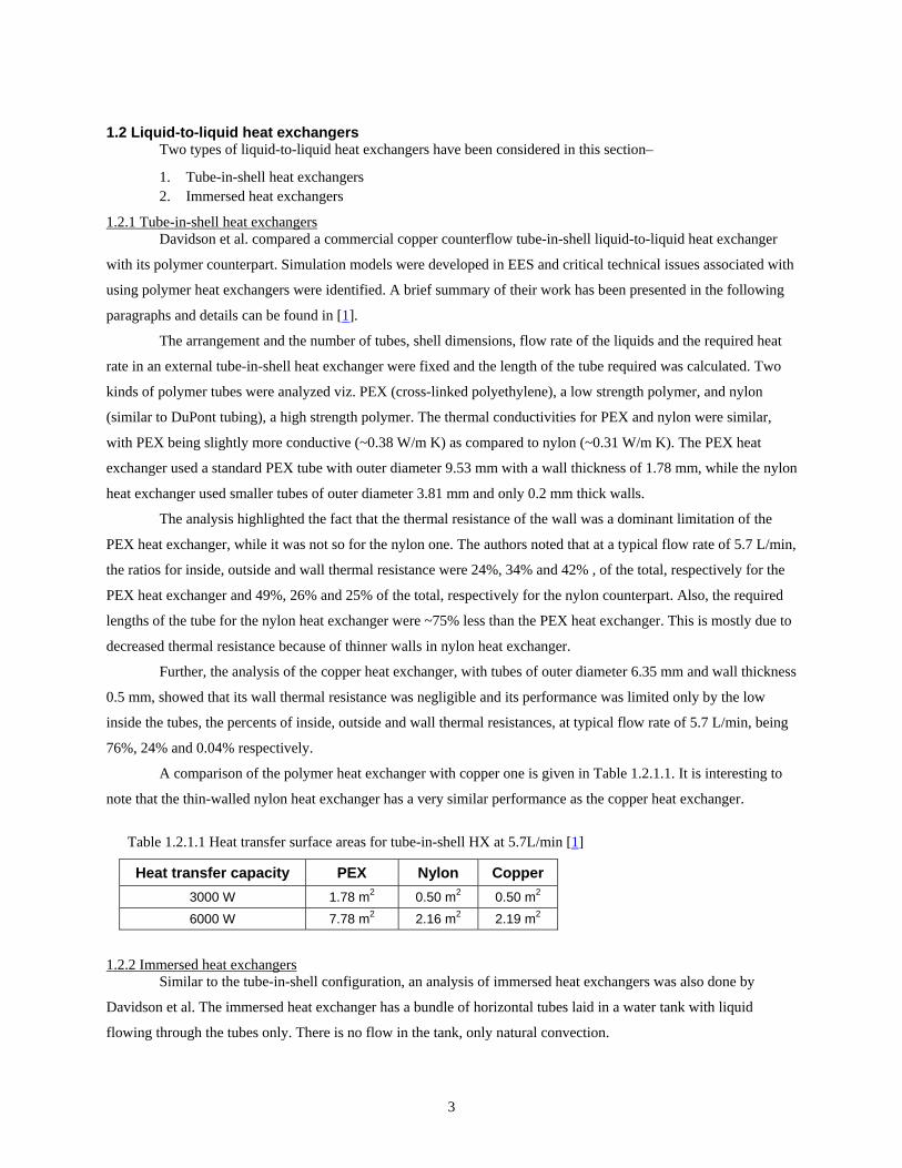
A comparison of the polymer heat exchanger with copper one is given in Table 1.2.1.1. It is interesting to
note that the thin-walled nylon heat exchanger has a very similar performance as the copper heat exchanger.
Table 1.2.1.1 Heat transfer surface areas for tube-in-shell HX at 5.7L/min [1]
Heat transfer capacity PEX Nylon Copper 3000 W 1.78 m2 0.50 m2 0.50 m2 6000 W 7.78 m2 2.16 m2 2.19 m2
1.2.2 Immersed heat exchangers Similar to the tube-in-shell configuration, an analysis of immersed heat exchangers was also done by
Davidson et al. The immersed heat exchanger has a bundle of horizontal tubes laid in a water tank with liquid
flowing through the tubes only. There is no flow in the tank, only natural convection.
4
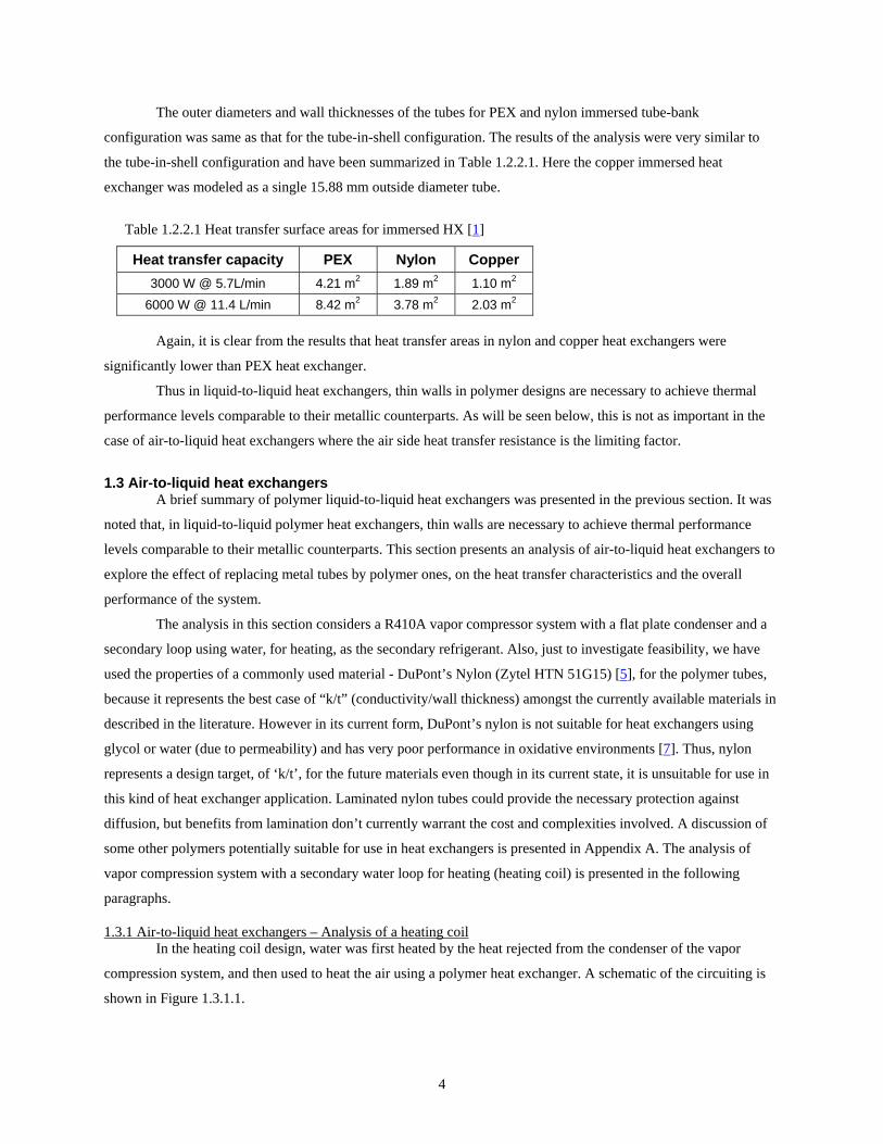
The outer diameters and wall thicknesses of the tubes for PEX and nylon immersed tube-bank
configuration was same as that for the tube-in-shell configuration. The results of the analysis were very similar to
the tube-in-shell configuration and have been summarized in Table 1.2.2.1. Here the copper immersed heat
exchanger was modeled as a single 15.88 mm outside diameter tube.
Table 1.2.2.1 Heat transfer surface areas for immersed HX [1]
Heat transfer capacity PEX Nylon Copper 3000 W @ 5.7L/min 4.21 m2 1.89 m2 1.10 m2
6000 W @ 11.4 L/min 8.42 m2 3.78 m2 2.03 m2
Again, it is clear from the results that heat transfer areas in nylon and copper heat exchangers were
significantly lower than PEX heat exchanger.
Thus in liquid-to-liquid heat exchangers, thin walls in polymer designs are necessary to achieve thermal
performance levels comparable to their metallic counterparts. As will be seen below, this is not as important in the
case of air-to-liquid heat exchangers where the air side heat transfer resistance is the limiting factor.
1.3 Air-to-liquid heat exchangers A brief summary of polymer liquid-to-liquid heat exchangers was presented in the previous section. It was
noted that, in liquid-to-liquid polymer heat exchangers, thin walls are necessary to achieve thermal performance
levels comparable to their metallic counterparts. This section presents an analysis of air-to-liquid heat exchangers to
explore the effect of replacing metal tubes by polymer ones, on the heat transfer characteristics and the overall
performance of the system.
The analysis in this section considers a R410A vapor compressor system with a flat plate condenser and a
secondary loop using water, for heating, as the secondary refrigerant. Also, just to investigate feasibility, we have
used the properties of a commonly used material - DuPont’s Nylon (Zytel HTN 51G15) [5], for the polymer tubes,
because it represents the best case of “k/t” (conductivity/wall thickness) amongst the currently available materials in
described in the literature. However in its current form, DuPont’s nylon is not suitable for heat exchangers using
glycol or water (due to permeability) and has very poor performance in oxidative environments [7]. Thus, nylon
represents a design target, of ‘k/t’, for the future materials even though in its current state, it is unsuitable for use in
this kind of heat exchanger application. Laminated nylon tubes could provide the necessary protection against
diffusion, but benefits from lamination don’t currently warrant the cost and complexities involved. A discussion of
some other polymers potentially suitable for use in heat exchangers is presented in Appendix A. The analysis of
vapor compression system with a secondary water loop for heating (heating coil) is presented in the following
paragraphs.
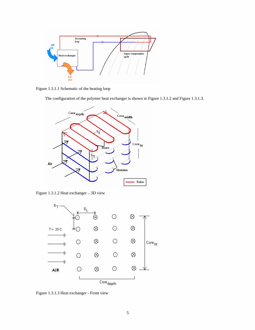
1.3.1 Air-to-liquid heat exchangers – Analysis of a heating coil In the heating coil design, water was first heated by the heat rejected from the condenser of the vapor
compression system, and then used to heat the air using a polymer heat exchanger. A schematic of the circuiting is
shown in Figure 1.3.1.1.
5
Figure 1.3.1.1 Schematic of the heating loop
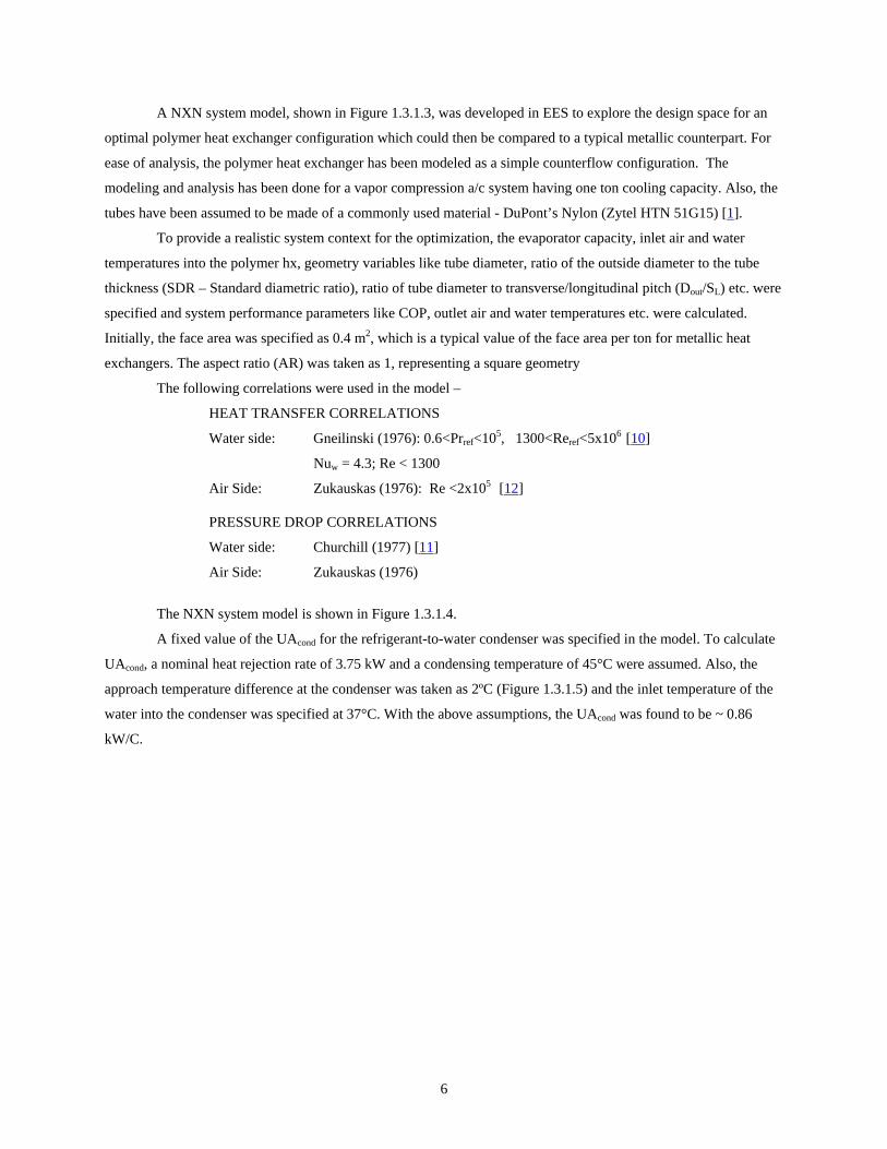
The configuration of the polymer heat exchanger is shown in Figure 1.3.1.2 and Figure 1.3.1.3.
Figure 1.3.1.2 Heat exchanger – 3D view
Figure 1.3.1.3 Heat exchanger - Front view
6
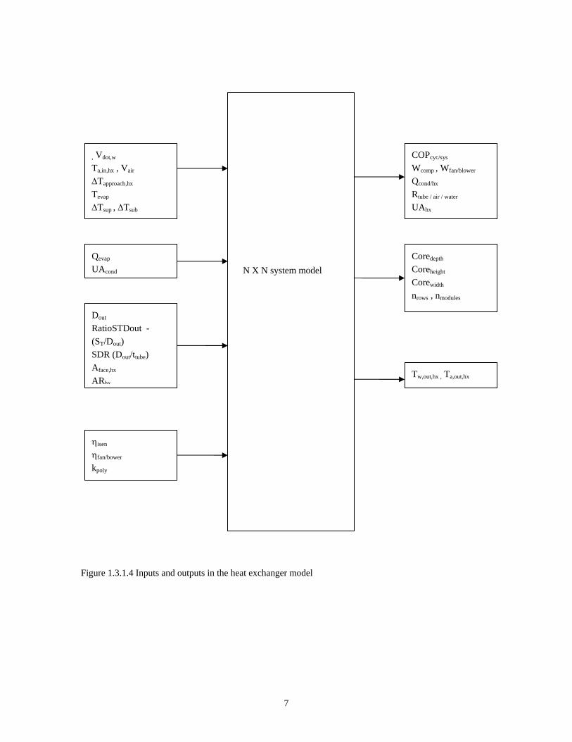
A NXN system model, shown in Figure 1.3.1.3, was developed in EES to explore the design space for an
optimal polymer heat exchanger configuration which could then be compared to a typical metallic counterpart. For
ease of analysis, the polymer heat exchanger has been modeled as a simple counterflow configuration. The
modeling and analysis has been done for a vapor compression a/c system having one ton cooling capacity. Also, the
tubes have been assumed to be made of a commonly used material - DuPont’s Nylon (Zytel HTN 51G15) [1].
To provide a realistic system context for the optimization, the evaporator capacity, inlet air and water
temperatures into the polymer hx, geometry variables like tube diameter, ratio of the outside diameter to the tube
thickness (SDR – Standard diametric ratio), ratio of tube diameter to transverse/longitudinal pitch (Dout/SL) etc. were
specified and system performance parameters like COP, outlet air and water temperatures etc. were calculated.
Initially, the face area was specified as 0.4 m2, which is a typical value of the face area per ton for metallic heat
exchangers. The aspect ratio (AR) was taken as 1, representing a square geometry
The following correlations were used in the model –
HEAT TRANSFER CORRELATIONS
Water side: Gneilinski (1976): 0.6<Prref<105, 1300<Reref<5x10⁶ [10]
Nuw = 4.3; Re < 1300
Air Side: Zukauskas (1976): Re <2x10⁵ [12]
PRESSURE DROP CORRELATIONS
Water side: Churchill (1977) [11]
Air Side: Zukauskas (1976)
The NXN system model is shown in Figure 1.3.1.4.
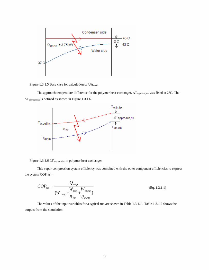
A fixed value of the UAcond for the refrigerant-to-water condenser was specified in the model. To calculate
UAcond, a nominal heat rejection rate of 3.75 kW and a condensing temperature of 45°C were assumed. Also, the
approach temperature difference at the condenser was taken as 2ºC (Figure 1.3.1.5) and the inlet temperature of the
water into the condenser was specified at 37°C. With the above assumptions, the UAcond was found to be ~ 0.86
kW/C.
7
Figure 1.3.1.4 Inputs and outputs in the heat exchanger model
N X N system model
, Vdot,w Ta,in,hx , Vair
∆Tapproach,hx
Tevap
∆Tsup , ∆Tsub
Qevap UAcond
Dout RatioSTDout - (ST/Dout) SDR (Dout/ttube) Aface,hx
ARhx
ηisen ηfan/bower
kpoly
COPcyc/sys
Wcomp , Wfan/blower
Qcond/hx
Rtube / air / water UAhx
Coredepth Coreheight Corewidth nrows , nmodules
Tw,out,hx , Ta,out,hx
8
Figure 1.3.1.5 Base case for calculation of UAcond
The approach temperature difference for the polymer heat exchanger, ∆Tapproach,hx, was fixed at 2°C. The
∆Tapproach,hx is defined as shown in Figure 1.3.1.6.
Figure 1.3.1.6 ∆Tapproach,hx in polymer heat exchanger
This vapor compression system efficiency was combined with the other component efficiencies to express
the system COP as –
)(pump
pump
fan
fancomp
evapsys WW
W
QCOP
ηη++
= (Eq. 1.3.1.1)
The values of the input variables for a typical run are shown in Table 1.3.1.1. Table 1.3.1.2 shows the
outputs from the simulation.

9
Table 1.3.1.1 Input variables for typical hot HX simulation
Variable Value Notes Qevap 3.5 kW 1-ton
UAcond 0.86 kW/K Assumed value Dout 4 mm Initial guess
SDR (Dout/ttube) 15 Initial guess RatioSTDout 2 Initial guess
Aface 0.4 m2 Typical of air cooled cond.
∆Tapproach,hx 2 C Initial guess
Vw 0.00015m3/s (2.5 gpm) Initial guess Vface,air 1.0 m/s Typical of air cooled cond. Tair,in 35 C Rating condition Tevap 12 C Ensure dehumidification
∆Tsup 5 C TXV or EEV
∆Tsub 5 C Typical at rating condition
ηpump/fan 0.2 Assumed pump/fan efficiency
ηisen 0.7 Assumed isentropic efficiency
ktube 0.31 W/mK Nylon conductivity
Table 1.3.1.2 Outputs from hot HX simulation
Output ~Value ttube 0.26 mm
Corewidth 0.63 m Coreheight 0.63 m Coredepth 0.30 m
nrows 38 nmodules 79
ntotal 3010 Tw,,in,hx 45.8 C Tw,out,hx 39.6 C Tair,out 43.8 C UAhx 1.3 kW/K
COPcyc 4.28 COPsys 4.06
At this point, it would be appropriate to establish a benchmark COP for a better understanding of the effect
of different parameters on the polymer heat exchanger performance and overall system performance. Also, this
allows us to quantify the inefficiencies incurred by adding a secondary heating loop instead of using the condenser
to directly heat the air. Consider the vapor compression cycle shown in Figure 1.3.1.7 in which there is no pressure
drop in the condenser and the condenser temperature is equal to the ambient temperature. The remainder of the cycle
is characterized by 5°C superheat, a 12°C evaporator temperature, and an isentropic efficiency of the compressor of
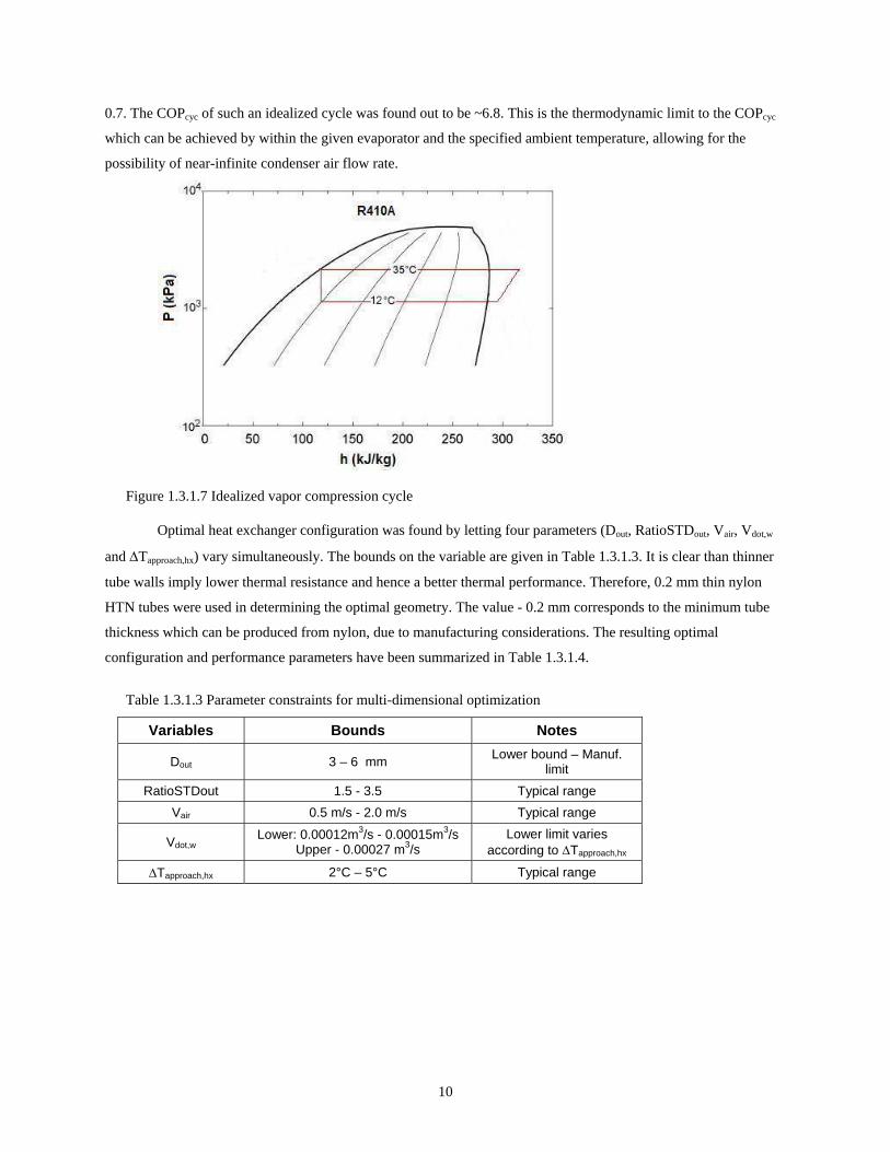
10
0.7. The COPcyc of such an idealized cycle was found out to be ~6.8. This is the thermodynamic limit to the COPcyc
which can be achieved by within the given evaporator and the specified ambient temperature, allowing for the
possibility of near-infinite condenser air flow rate.
Figure 1.3.1.7 Idealized vapor compression cycle
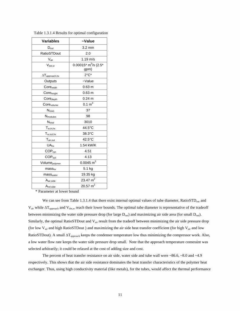
Optimal heat exchanger configuration was found by letting four parameters (Dout, RatioSTDout, Vair, Vdot,w
and ∆Tapproach,hx) vary simultaneously. The bounds on the variable are given in Table 1.3.1.3. It is clear than thinner
tube walls imply lower thermal resistance and hence a better thermal performance. Therefore, 0.2 mm thin nylon
HTN tubes were used in determining the optimal geometry. The value - 0.2 mm corresponds to the minimum tube
thickness which can be produced from nylon, due to manufacturing considerations. The resulting optimal
configuration and performance parameters have been summarized in Table 1.3.1.4.
Table 1.3.1.3 Parameter constraints for multi-dimensional optimization
Variables Bounds Notes
Dout 3 – 6 mm Lower bound – Manuf. limit
RatioSTDout 1.5 - 3.5 Typical range Vair 0.5 m/s - 2.0 m/s Typical range
Vdot,w Lower: 0.00012m3/s - 0.00015m3/sUpper - 0.00027 m3/s
Lower limit varies according to ∆Tapproach,hx
∆Tapproach,hx 2°C – 5°C Typical range
11
Table 1.3.1.4 Results for optimal configuration
Variables ~Value Dout 3.2 mm
RatioSTDout 2.0 Vair 1.19 m/s
Vdot,w 0.00015* m3/s (2.5* gpm)
∆Tapproach,hx 2°C*
Outputs ~Value Corewidth 0.63 m Coreheight 0.63 m Coredepth 0.24 m Corevolume 0.1 m3
Nrows 37 Nmodules 98
Ntotal 3010 Tw,in,hx 44.5°C Tw,out,hx 38.3°C Tair,out 42.5°C UAhx 1.54 kW/K
COPcyc 4.51 COPsys 4.13
Volumepolymer 0.0045 m3 masshx 5.1 kg
masswater 19.35 kg Aair,side 23.47 m2 Aref,side 20.57 m2
* Parameter at lower bound
We can see from Table 1.3.1.4 that there exist internal optimal values of tube diameter, RatioSTDout and
Vair while ∆Tapproach and Vdot,w reach their lower bounds. The optimal tube diameter is representative of the tradeoff
between minimizing the water side pressure drop (for large Dout) and maximizing air side area (for small Dout).
Similarly, the optimal RatioSTDout and Vair result from the tradeoff between minimizing the air side pressure drop
(for low Vair and high RatioSTDout ) and maximizing the air side heat transfer coefficient (for high Vair and low
RatioSTDout). A small ∆Tapproach keeps the condenser temperature low thus minimizing the compressor work. Also,
a low water flow rate keeps the water side pressure drop small. Note that the approach temperature constraint was
selected arbitrarily; it could be relaxed at the cost of adding size and cost.
The percent of heat transfer resistance on air side, water side and tube wall were ~86.6, ~8.0 and ~4.9
respectively. This shows that the air side resistance dominates the heat transfer characteristics of the polymer heat
exchanger. Thus, using high conductivity material (like metals), for the tubes, would affect the thermal performance

12
only marginally. The major difference in performance between this polymer heat exchanger and its metal
counterpart is due to its lack of extended surfaces.
The optimized tube bundle configuration can be compared to a typical microchannel heat condenser in a
one-ton air conditioner. A comparison of the performance and dimensions of the polymer and metallic heat
exchanger is given in Table 1.3.1.5.
It can be seen by comparing Tables 1.3.1.4 and 1.3.1.5 that for almost equal system performance, the
metallic heat exchanger requires 20 times less core volume than the polymer heat exchanger, which is composed of
~3000 small thin tubes. Specifically, the volume of the material used in the polymer heat exchanger is ~0.0045m3,
which is much more than the volume of metal in microchannel heat exchanger (~ 0.0011 m3) and ~40 % heavier
than the metallic one. When the mass of water is added, the polymer hx becomes almost six times as massive as the
microchannel refrigerant-to-air condenser.
Table 1.3.1.5: Typical one-ton microchannel condenser simulation results
Parameter Metallic hx (R410A system) Qevap 3.5 kW Aface 0.4 m2
∆Tapproach 2°C
Corewidth 6.05 m Coreheight 0.077 m Coredepth 0.011 m Corevolume 0.0054 m3
Volumemetal 0.0011 m3 massmetal 3.06 kg
Aair,side 9.38 m2 Aref,side 1.15 m2
1.3.2 Air-to-liquid heat exchangers – Analysis of a cooling coil In this design, water is first cooled by the evaporator of a vapor compression system, and then used to cool
the air using a polymer heat exchanger. A schematic of the circuiting is shown in Figure 1.3.2.1.

13
Figure 1.3.2.1 Schematic of the cooling loop
The configuration of the polymer heat exchanger is similar to the heating loop, as shown in Figure 1.3.1.2
and Figure 1.3.1.3.
Similar to the heating loop analysis, EES was used to solve the NxN set of simultaneous equations to
explore the design space for an optimal polymer heat exchanger configuration, which was then compared to a
typical metallic counterpart. For ease of analysis, the polymer heat exchanger was modeled as a counterflow
configuration, a reasonable approximation when the number of passes is greater than 3. Again, the modeling and
analysis was done for a vapor compression system with a capacity of one ton and the properties of DuPont’s Nylon
(Zytel HTN 51G15) were assumed for the tube material.
In the model (Figure 2), the condenser temperature, inlet air and water temperatures into the polymer hx,
geometry variables like tube diameter, ratio of the outside diameter to the tube thickness (SDR – Standard diametric
ratio), ratio of tube diameter to transverse/longitudinal pitch (Dout/SL) etc. were specified and system performance
parameters like COP, outlet air and water temperatures etc. were calculated. The face area was specified as 0.4 m2,
which is a typical value of the face area per ton for metallic evaporators of the type used in ductless mini-split
systems. In ducted split systems, the face area can be significantly smaller. The aspect ratio (AR) was taken as 1,
representing a square geometry
The following correlations were used in the model –
HEAT TRANSFER CORRELATIONS
Water side: Gneilinski (1976): 0.6<Prref<105, 1300<Reref<5x10⁶ [10]
Nuw = 4.3 ; Re < 1300
Air Side: Zukauskas (1976): Re <2x10⁵ [12]
PRESSURE DROP CORRELATIONS
Water side Churchill (1977) [11]
Air Side: Zukauskas (1976)
14
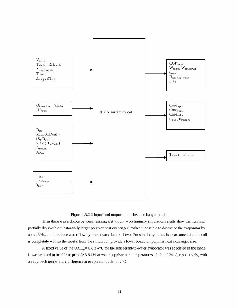
Figure 1.3.2.2 Inputs and outputs in the heat exchanger model
Then there was a choice between running wet vs. dry – preliminary simulation results show that running
partially dry (with a substantially larger polymer heat exchanger) makes it possible to downsize the evaporator by
about 30%, and to reduce water flow by more than a factor of two. For simplicity, it has been assumed that the coil
is completely wet, so the results from the simulation provide a lower bound on polymer heat exchanger size.
A fixed value of the UAevap = 0.8 kW/C for the refrigerant-to-water evaporator was specified in the model.
It was selected to be able to provide 3.5 kW at water supply/return temperatures of 12 and 20°C, respectively, with
an approach temperature difference at evaporator outlet of 2°C.
N X N system model
Vdot_w Ta,in,hx , RHa,in,air
∆Tapproach,hx Tcond ∆Tsup , ∆Tsub
Qindoor/evap , SHR, UAevap
Dout RatioSTDout - (ST/Dout) SDR (Dout/ttube) Aface,hx ARhx
ηisen ηfan/bower kpoly
COPcyc/sys Wcomp , Wfan/blower Qeond Rtube / air / water UAhx
Coredepth Coreheight Corewidth nrows , nmodules
Tw,out,hx , Ta,out,hx
15
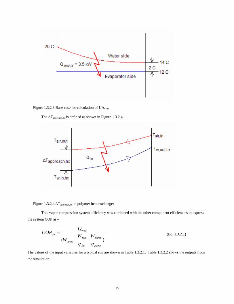
Figure 1.3.2.3 Base case for calculation of UAevap
The ∆Tapproach,hx is defined as shown in Figure 1.3.2.4.
Figure 1.3.2.4 ∆Tapproach,hx in polymer heat exchanger
This vapor compression system efficiency was combined with the other component efficiencies to express
the system COP as –
)(pump
pump
fan
fancomp
evapsys WW
W
QCOP
ηη++
= (Eq. 1.3.2.1)
The values of the input variables for a typical run are shown in Table 1.3.2.1. Table 1.3.2.2 shows the outputs from
the simulation.
16
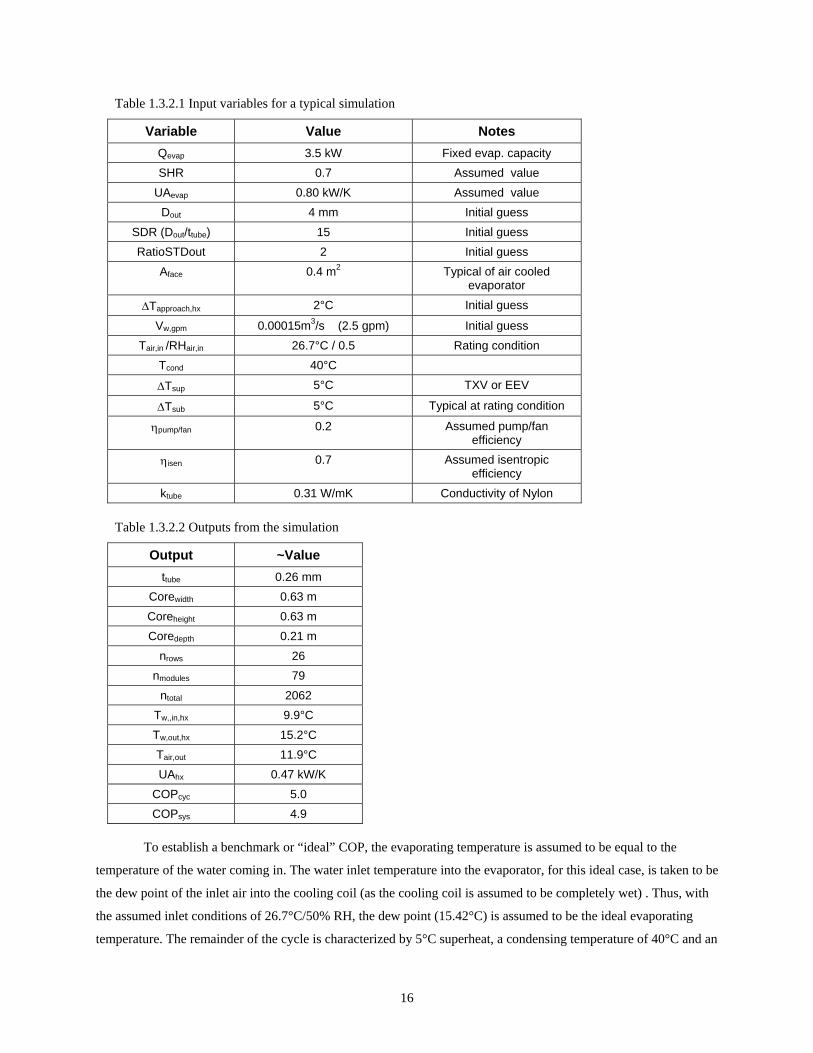
Table 1.3.2.1 Input variables for a typical simulation
Variable Value Notes Qevap 3.5 kW Fixed evap. capacity SHR 0.7 Assumed value
UAevap 0.80 kW/K Assumed value Dout 4 mm Initial guess
SDR (Dout/ttube) 15 Initial guess RatioSTDout 2 Initial guess
Aface 0.4 m2 Typical of air cooled evaporator
∆Tapproach,hx 2°C Initial guess
Vw,gpm 0.00015m3/s (2.5 gpm) Initial guess Tair,in /RHair,in 26.7°C / 0.5 Rating condition
Tcond 40°C
∆Tsup 5°C TXV or EEV
∆Tsub 5°C Typical at rating condition
ηpump/fan 0.2 Assumed pump/fan efficiency
ηisen 0.7 Assumed isentropic efficiency
ktube 0.31 W/mK Conductivity of Nylon
Table 1.3.2.2 Outputs from the simulation
Output ~Value ttube 0.26 mm
Corewidth 0.63 m Coreheight 0.63 m Coredepth 0.21 m
nrows 26 nmodules 79
ntotal 2062 Tw,,in,hx 9.9°C Tw,out,hx 15.2°C Tair,out 11.9°C UAhx 0.47 kW/K
COPcyc 5.0 COPsys 4.9
To establish a benchmark or “ideal” COP, the evaporating temperature is assumed to be equal to the
temperature of the water coming in. The water inlet temperature into the evaporator, for this ideal case, is taken to be
the dew point of the inlet air into the cooling coil (as the cooling coil is assumed to be completely wet) . Thus, with
the assumed inlet conditions of 26.7°C/50% RH, the dew point (15.42°C) is assumed to be the ideal evaporating
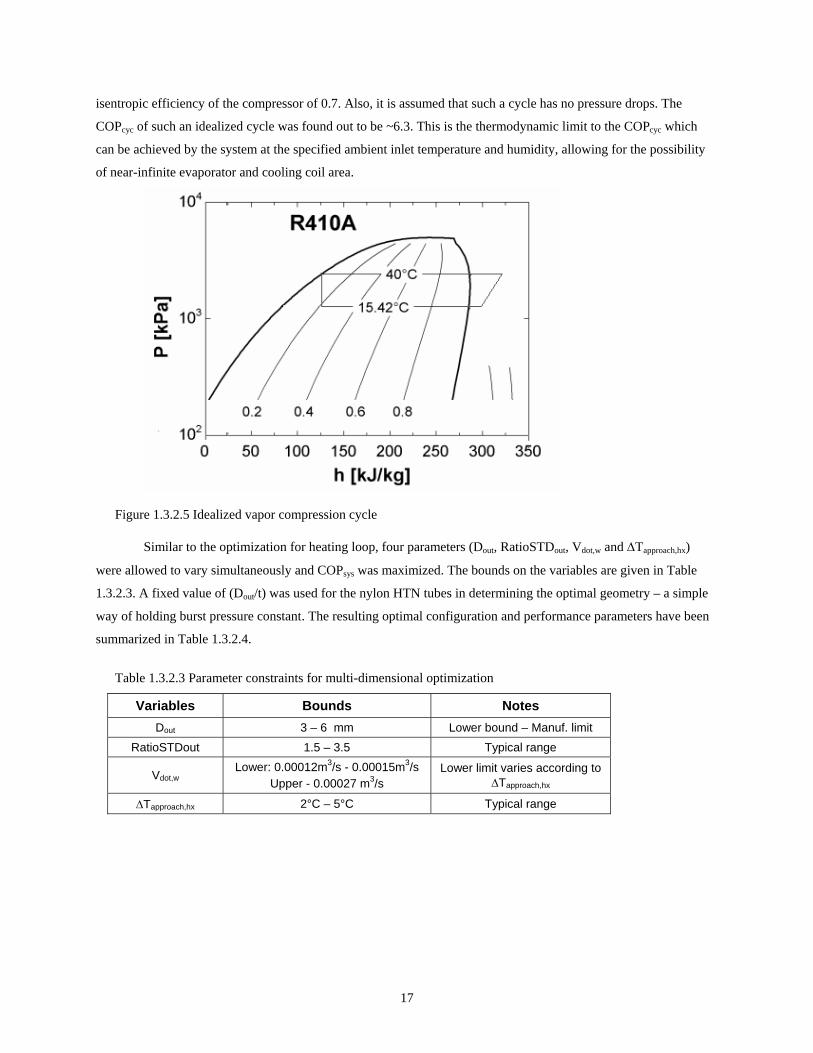
temperature. The remainder of the cycle is characterized by 5°C superheat, a condensing temperature of 40°C and an
17
isentropic efficiency of the compressor of 0.7. Also, it is assumed that such a cycle has no pressure drops. The
COPcyc of such an idealized cycle was found out to be ~6.3. This is the thermodynamic limit to the COPcyc which
can be achieved by the system at the specified ambient inlet temperature and humidity, allowing for the possibility
of near-infinite evaporator and cooling coil area.
Figure 1.3.2.5 Idealized vapor compression cycle
Similar to the optimization for heating loop, four parameters (Dout, RatioSTDout, Vdot,w and ∆Tapproach,hx)
were allowed to vary simultaneously and COPsys was maximized. The bounds on the variables are given in Table
1.3.2.3. A fixed value of (Dout/t) was used for the nylon HTN tubes in determining the optimal geometry – a simple
way of holding burst pressure constant. The resulting optimal configuration and performance parameters have been
summarized in Table 1.3.2.4.
Table 1.3.2.3 Parameter constraints for multi-dimensional optimization
Variables Bounds Notes Dout 3 – 6 mm Lower bound – Manuf. limit
RatioSTDout 1.5 – 3.5 Typical range
Vdot,w Lower: 0.00012m3/s - 0.00015m3/s
Upper - 0.00027 m3/s Lower limit varies according to
∆Tapproach,hx
∆Tapproach,hx 2°C – 5°C Typical range
18
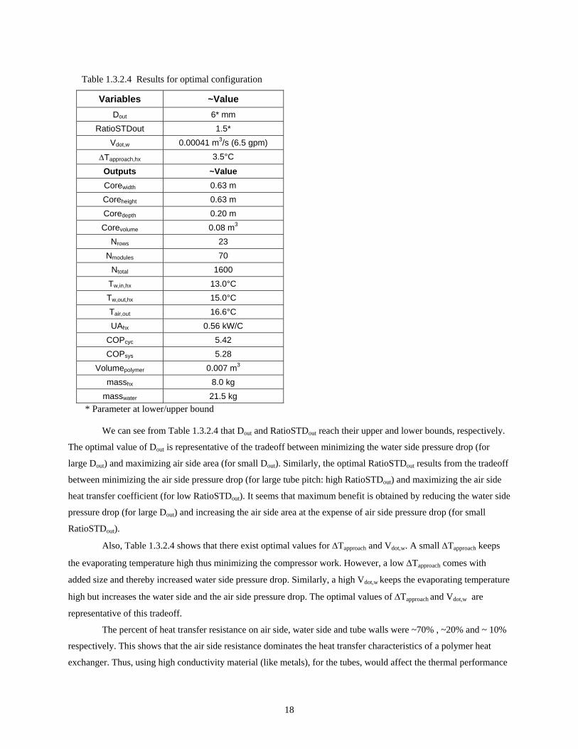
Table 1.3.2.4 Results for optimal configuration
Variables ~Value Dout 6* mm
RatioSTDout 1.5* Vdot,w 0.00041 m3/s (6.5 gpm)
∆Tapproach,hx 3.5°C
Outputs ~Value Corewidth 0.63 m Coreheight 0.63 m Coredepth 0.20 m Corevolume 0.08 m3
Nrows 23 Nmodules 70
Ntotal 1600 Tw,in,hx 13.0°C Tw,out,hx 15.0°C Tair,out 16.6°C UAhx 0.56 kW/C
COPcyc 5.42 COPsys 5.28
Volumepolymer 0.007 m3 masshx 8.0 kg
masswater 21.5 kg * Parameter at lower/upper bound
We can see from Table 1.3.2.4 that Dout and RatioSTDout reach their upper and lower bounds, respectively.
The optimal value of Dout is representative of the tradeoff between minimizing the water side pressure drop (for
large Dout) and maximizing air side area (for small Dout). Similarly, the optimal RatioSTDout results from the tradeoff
between minimizing the air side pressure drop (for large tube pitch: high RatioSTDout) and maximizing the air side
heat transfer coefficient (for low RatioSTDout). It seems that maximum benefit is obtained by reducing the water side
pressure drop (for large Dout) and increasing the air side area at the expense of air side pressure drop (for small
RatioSTDout).
Also, Table 1.3.2.4 shows that there exist optimal values for ∆Tapproach and Vdot,w. A small ∆Tapproach keeps
the evaporating temperature high thus minimizing the compressor work. However, a low ∆Tapproach comes with
added size and thereby increased water side pressure drop. Similarly, a high Vdot,w keeps the evaporating temperature
high but increases the water side and the air side pressure drop. The optimal values of ∆Tapproach and Vdot,w are
representative of this tradeoff.
The percent of heat transfer resistance on air side, water side and tube walls were ~70% , ~20% and ~ 10%
respectively. This shows that the air side resistance dominates the heat transfer characteristics of a polymer heat
exchanger. Thus, using high conductivity material (like metals), for the tubes, would affect the thermal performance
19
only marginally. The major difference in performance between this polymer heat exchanger and its metal
counterpart is due to its lack of extended surfaces.
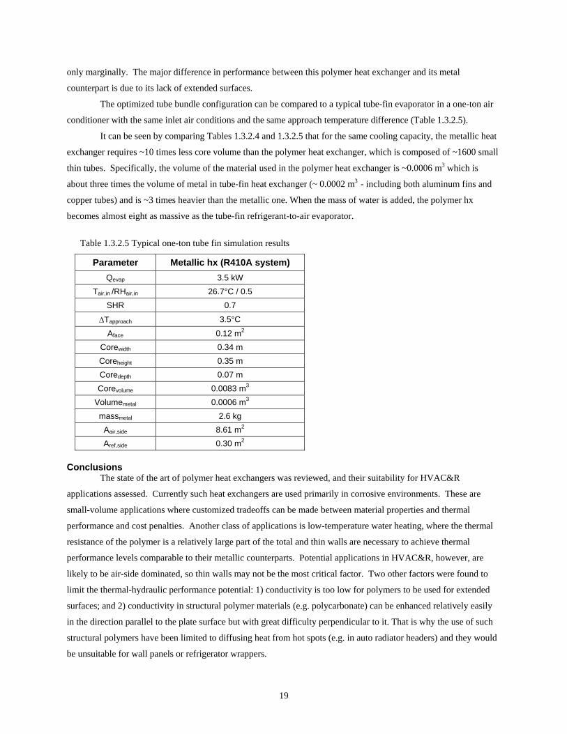
The optimized tube bundle configuration can be compared to a typical tube-fin evaporator in a one-ton air
conditioner with the same inlet air conditions and the same approach temperature difference (Table 1.3.2.5).
It can be seen by comparing Tables 1.3.2.4 and 1.3.2.5 that for the same cooling capacity, the metallic heat
exchanger requires ~10 times less core volume than the polymer heat exchanger, which is composed of ~1600 small
thin tubes. Specifically, the volume of the material used in the polymer heat exchanger is ~0.0006 m3 which is
about three times the volume of metal in tube-fin heat exchanger (~ 0.0002 m3 - including both aluminum fins and
copper tubes) and is ~3 times heavier than the metallic one. When the mass of water is added, the polymer hx
becomes almost eight as massive as the tube-fin refrigerant-to-air evaporator.
Table 1.3.2.5 Typical one-ton tube fin simulation results
Parameter Metallic hx (R410A system) Qevap 3.5 kW
Tair,in /RHair,in 26.7°C / 0.5 SHR 0.7
∆Tapproach 3.5°C
Aface 0.12 m2 Corewidth 0.34 m Coreheight 0.35 m Coredepth 0.07 m Corevolume 0.0083 m3
Volumemetal 0.0006 m3 massmetal 2.6 kg
Aair,side 8.61 m2 Aref,side 0.30 m2
Conclusions The state of the art of polymer heat exchangers was reviewed, and their suitability for HVAC&R
applications assessed. Currently such heat exchangers are used primarily in corrosive environments. These are
small-volume applications where customized tradeoffs can be made between material properties and thermal
performance and cost penalties. Another class of applications is low-temperature water heating, where the thermal
resistance of the polymer is a relatively large part of the total and thin walls are necessary to achieve thermal
performance levels comparable to their metallic counterparts. Potential applications in HVAC&R, however, are
likely to be air-side dominated, so thin walls may not be the most critical factor. Two other factors were found to
limit the thermal-hydraulic performance potential: 1) conductivity is too low for polymers to be used for extended
surfaces; and 2) conductivity in structural polymer materials (e.g. polycarbonate) can be enhanced relatively easily
in the direction parallel to the plate surface but with great difficulty perpendicular to it. That is why the use of such
structural polymers have been limited to diffusing heat from hot spots (e.g. in auto radiator headers) and they would
be unsuitable for wall panels or refrigerator wrappers.
20
A simulation model was developed to get a quantitative estimate of the thermal and material tradeoffs
incurred by using polymers in a heating coil tube bundle. Results for a hypothetical 1-ton a/c system showed that
systems with optimally-configured polymer heat exchangers could achieve thermal performance similar to their
metallic counterparts. But, because of lack of extended surfaces, exchangers are ~ 6 times more massive, and occupy
~ 20 times more volume than conventional microchannel heat exchangers.
The simulation model was also used to explore the potential for using polymer materials to construct tube
bundles for cooling coils and cooling tower applications. Such heat exchangers could conceivably be used in
secondary loops to facilitate charge minimization in chillers and in systems using toxic or flammable refrigerants,
e.g. in vehicles and residential applications. Again, the results showed that an optimally-configured 1 ton a/c system
with polymer heat exchangers could achieve thermal performance similar to their metallic counterparts. But, the
polymer heat exchanger would be ~ 8 times more massive and occupy ~10 times more volume than conventional
tube and fin coils. This estimate is based on a ‘fully wet’ coil and represents a lower bound on such heat exchangers.
Actual coils, which might be running fully/partially dry, would be even more massive.
These results were obtained assuming the thermal, structural and (wall thickness) manufacturability
characteristics of nylon. However nylon has other characteristics (e.g. oxidation, moisture permeability) that would
have to be overcome by advanced materials before polymer heat exchangers could achieve the performance
calculated here.
Another problem that would need to be solved is that of connecting hundreds of tubes to headers. Until
these outstanding issues are resolved, polymer heat exchangers are unlikely to find widespread use in the HVAC&R
industry.
REFERENCES 1. Davidson, J. and S. Mantell, “Use of polymers in liquid-to-liquid heat exchangers; Applied to low-cost solar
water heating systems”, Task III Report, University of Minnesota, 1998. 2. Heating, L. W., J. H. Davidson, R. Raman and S. C. Mantell, “Thermal and economic analysis of plastic heat
exchangers for solar water”, Proceedings SOLAR '99, ASES, Portland, ME. 3. http://www.me.umn.edu/divisions/environmental/solar/research.htm 4. Shannon, M. A., M. L. Philpott, N. R. Miller, C. W. Bullard, D. J. Beebe, A. M. Jacobi, P. S. Hrnjak, T. Saif,
N. Aluru, H. Sehitoglu, A. Rockett and J. Economy, “Integrated mesoscopic cooler circuits (IMCCS),” Proceedings of the 1999 International Mechanical Engineering Congress and Exposition, Nashville, TN, AES-Vol. 39, pp. 75-81, November 1999.
5. http://www.microplastics.com/Materials/NYLON%2066.htm 6. Barnes, P.R. and C. W. Bullard, “Minimizing TEWI by charge reduction in a compact chiller”, ACRC TR-
176, August 2000. 7. Davidson, J., University of Minnesota, personal communication, 2004. 8. Rubio, M., Fafco Co., personal communication, 2004. 9. Gneilinski, V., “New equations for heat and mass transfer in turbulent pipe and channel flow”, Int .Chem.
Eng., Vol. 16, pp. 359-368, 1976. 10. Churchill, S. W., “Friction-factor equations spans all fluid flow regimes”, Chemical Engineering, pp. 91-92,
1977. 11. Zukauskas, A. and Ulinskas, R. “Efficiency parameters for heat transfer in tube banks”, Heat Transfer
Engineering, 6:2 pp 19-25, 1985.
21
Appendix A. Polymers for Use in Heat Exchangers
The literature review was conducted by contacting companies involved in design and production of
polymer heat exchangers (like DuPont, Fafco, Ametek etc.), and the government agency funding such research
(DoE’s National Renewable Energy Laboratory and its contractor, the Univ. of Minnesota). This provided the basis
for identifying promising polymer materials suitable for use with liquid-to-liquid heat exchangers with a design
pressure requirement of ~1.1 MPa. A brief summary of their work is presented here. Polymer materials for air-to-air
and air-to-liquid heat exchangers can be selected on similar guidelines. A more detailed discussion of liquid-to-
liquid heat exchangers is out of the scope of this project.
A review of the available literature revealed that many of the commercially available polymer heat
exchangers are made of rather expensive fluoropolymers (polyvinylidine fluoride (PVDF), Teflon), or materials like
polypropylene (PP), which are not suitable for use with water over 60° C.
It was recognized that the selection of appropriate material/s for heat transfer application depends on the
following six factors:
1. Thermal conductivity
2. Strength and stiffness
3. Temperature limits (thermal index, glass transition temperature etc.)
4. Refrigerant/Water absorption and diffusion properties
5. NSF codes and standards for the targeted application and
6. Cost
Issues related to permeability of the polymer to water, chemical resistance to chlorinated water, ions found
in potable water, mating to piping and tanks, ease of repairs, and compliance with applicable plumbing codes were
also addressed.
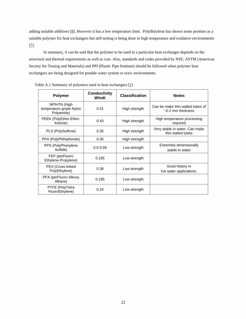
The polymers in Table A.1 were identified as suitable for use with water/glycol.
The polymers were classified on the basis of their tensile strength and flexural modulus. Polymers having
tensile strength >80 MPa and flexural modulus >2500 MPa were classified as ‘high strength’ and others were
categorized as ‘low strength’ polymers. All the polymers, in Table A.1, absorbed < 1% of water by weight after 24
hrs of being immersed in water.
Of all the high strength polymers chosen, nylon polyamide (NP) had the lowest cost while cross-linked
polyethylene (PEX) was the least costly of the low strength polymers.
High strength polymers can be used to make thin-walled components for heat exchangers (e.g. thin tubes
and sheets) while low strength polymers require thick walls, which hinder their heat transfer performance. But low
strength polymers are usually cheaper and can be used in heat exchanger components which require bending (e.g.
coiled tubes), as they have low flexural modulus.
Also, if the operating pressure and temperatures are low, then cheap plastics like PolyEthylene (PE) and
PolyPropylene (PP) can also be used. However, these materials are not resistant to propylene glycol, which is
commonly used on food-related applications. Polypropylene works well in water and its life can be extended by
22
adding suitable additives [8]. However it has a low temperature limit. PolyButylene has shown some promise as a
suitable polymer for heat exchangers but still testing is being done in high temperature and oxidative environments
[7].
In summary, it can be said that the polymer to be used in a particular heat exchanger depends on the
structural and thermal requirements as well as cost. Also, standards and codes provided by NSF, ASTM (American
Society for Testing and Materials) and PPI (Plastic Pipe Institute) should be followed when polymer heat
exchangers are being designed for potable water system or toxic environments.
Table A.1 Summary of polymers used in heat exchangers [1]
Polymer Conductivity W/mK Classification Notes
NP/HTN (High temperature grade Nylon
Polyamide) 0.31 High strength Can be make thin walled tubes of
~0.2 mm thickness
PEEK (PolyEther-Ether-Ketone) 0.43 High strength High temperature processing
required
PLS (PolySulfone) 0.26 High strength Very stable in water. Can make thin walled tubes
PPA (PolyPhthalAmide) 0.35 High strength
PPS (PolyPhenylene Sulfide) 0.5-0.59 Low strength
Extremely dimensionally stable in water
FEP (perFluoro Ethylene-Propylene) 0.195 Low strength
PEX (Cross linked PolyEthylene) 0.38 Low strength
Good history in hot water applications.
PFA (perFluoro Alkoxy Alkane) 0.195 Low strength
PTFE (PolyTetra FluoroEthylene) 0.24 Low strength