Embed Size (px)
Citation preview

Preliminary Analysis of Polymer Heat Exchangers for Ocean Thermal Energy Conversion Application
Todd TaniguchiDr. Hans Krock and OCEES International
Harvey Mudd Faculty Advisor: Peter Saeta
Summer 2006
i

Abstract
Heat exchangers account for about one-quarter of the total capital cost for a proposed 10 MW Ocean Thermal Energy Conversion (OTEC) power plant. The current system design uses titanium plate-and-frame exchangers. However, increased demand for titanium has decreased its availability and increased its price. This motivated an exploration of material alternatives to titanium. Polymers were targeted in particular because they represented an area of materials science where significant advances have been made in recent decades. While metal alternatives exist, most polymers are unaffected by seawater corrosion that often causes metal failure. An extensive literature search revealed that no heat exchanger manufacturer’s currently produce a polymer exchanger that can compete with the quoted price of the titanium heat exchangers for the design requirements of a closed-cycle OTEC plant. The remainder of the research period attempted to determine the feasibility of using polymers in current heat exchanger designs. However, evaluating these candidates was difficult due to the lack of pre-existing metrics for material evaluation. It was decided that thermal conductivity and mechanical robustness were the main factors that would allow a preliminary screening of polymer materials. Screening for high thermal conductivity, several commercially available polymers were found. However, difficulty with determining the maximum stress in current plate-and-frame designs prevented further mechanical analysis. It was hypothesized that polymer heat exchangers would currently be more competitive in seawater air-conditioning and cooling applications, where operating pressures might be significantly below that of the pressurized ammonia required for a closed-cycle OTEC plant.
i

Table of ContentsAbstract.................................................................................................................................iTable of Contents................................................................................................................iiTable of Figures..................................................................................................................iiiIntroduction..........................................................................................................................1Problem Background...........................................................................................................2Problem Statement...............................................................................................................2Project Objectives and Heat Exchanger Design Constraints...............................................3
Project Objectives............................................................................................................3Heat Exchanger Design Constraints................................................................................3
Technical Background.........................................................................................................4Overview: Ocean Thermal Energy Conversion (OTEC)................................................4
Brief History of Technology:.......................................................................................4Overview of OTEC Power Generation:.......................................................................4
Closed Cycle OTEC (CC-OTEC)............................................................................6Mechanical subsystems of interest: Heat Exchangers........................................................7
Types of Heat Exchangers...............................................................................................7Recuperative Type Heat Exchangers...........................................................................8
Shell and Tube Heat Exchangers.............................................................................8Plate-and-frame........................................................................................................9Matrix/Plate-Fin Heat Exchangers........................................................................11
Existing Technology......................................................................................................12Calorplast Polypropylene Heat Exchanger................................................................12
Elements of Heat Exchanger Design and Evaluation........................................................14Thermodynamics of Heat Exchanger Design................................................................14
Heat Transfer Equations............................................................................................14Performance Variables:..................................................................................................17
Plate-and-frame Heat Exchangers.............................................................................17Shell and Tube Exchangers.......................................................................................18Matrix Exchangers.....................................................................................................18
Material selection...........................................................................................................19Challenges in Polymer Heat Exchangers...................................................................19Advantages of Polymers............................................................................................20Chemistry: Metallic Corrosion vs. Polymer Corrosion............................................20
Stress Analysis...............................................................................................................22Results................................................................................................................................23Seawater District Cooling..................................................................................................25Brief Analysis of Cost Savings..........................................................................................26Conclusions........................................................................................................................27
Future Work...................................................................................................................27Further Social Context and Impact....................................................................................28
Natural Energy Laboratory of Hawai`i Authority (NELHA) Site Visit........................28Acknowledgements............................................................................................................29APPENDIX A: Calculations..............................................................................................30APPENDIX B: Material Property Data Sheets.................................................................36
ii

APPENDIX C: References................................................................................................41
Table of FiguresFigure 1: Simplified Heat Engine Block Diagram.............................................................5Figure 2: Shell and Tube Heat Exchanger..........................................................................8Figure 3: Plate-and-frame heat exchanger (PHE)...............................................................9Figure 4: Flow through a PHE............................................................................................9Figure 5: Single-pass and Multi-pass flow through a PHE..............................................10Figure 6: Multi-pass flow through a PHE.........................................................................10Figure 7: Matrix/Plate-Fin Heat Exchanger Plates...........................................................11Figure 8: Calorplast Polypropylene Polymer Heat Exchanger.........................................13Figure 9: Chevron Angles in Plate Heat Exchanger (Scan and add).................................17Figure 10: Material Properties Comparison Chart for Titanium and Polymers...............24Figure 11: Chart of estimated cost savings chart as dictated by changes in maintenance and capital costs.................................................................................................................26Figure 12: A Section of the HDPE pipe used to provide Cold-seawater to the NELHA facility................................................................................................................................28
iii

Introduction
Research done during this period revolved around the Ocean Thermal Energy Conversion (OTEC) system designs of Ocean Engineering and Energy Systems (OCEES) International, Inc, a firm dedicated to furthering OTEC development. With fossil fuels contributing to global warming, mankind urgently needs cleaner, affordable, and renewable energy sources, especially electrical energy sources.
In order to replace fossil fuels, these new energy sources must have a cost that can compete with conventional energy. In the past, the development of commercial OTEC power was hindered by its relatively high capital cost, coupled with relatively high interest rates and cost of oil.1 Even with an effective 25% federal tax discount on the total cost of a plant during the 1980s, no large scale commercial plant was built or even attempted during this time.2 In fact, even though the technology has certainly considered technically feasible since 1993, until recently (according to OCEES International) this technology has not been an attractive project.3
This relative economic disadvantage may be changing due to recent increases in crude oil prices. Between 1990 and 2000, the percentage of the Nation’s energy from petroleum has remained relatively constant at 40% and 38% respectively.4 The majority of this usage comes in the form of refined gasoline for automobile use. Petroleum-based power accounted for a small though not insignificant 1.8% of electrical power in 2003.5 During this 10 year period ending in 2000, the price of oil remained relatively stable and did not trade above $40 per barrel (numbers inflation adjusted to December 2005 dollars)6. Since then, though, the price of petroleum-based energy has risen with a spike in Light Sweet Crude Oil prices to the current level above $60/barrel7. This increase in the price of petroleum-based energy should cause the economics of alternative energies to improve comparatively, especially in areas with larger concentrations of petroleum based electrical power.
A clear example of this in the United States is Hawai`i, where the impact of rising oil prices is greatly magnified. In 2003, 80.8% of the states electrical energy came from petroleum-based sources.8 Thus, the state’s electrical energy cost is greatly affected by oil prices. Because of this, renewable energies, including OTEC, should now begin to receive a larger amount of support.
1 Mortgage-X.com. “Treasury Market and Mortgage Rates.” [October, 6, 2006] http://mortgage-x.com/general/treasury.asp2 Gielecki, Mark, Mayes, Fred, and Prete, Lawrence. Incentives, Mandates, and Government Programs for Promoting Renewable Energy.” (2001) [September 25, 2006] [http://www.eia.doe.gov/cneaf/solar.renewables/rea_issues/incent.html]3 National Renewable Energy Laboratory. "NREL: Ocean Thermal Energy Conversion” [September 23, 2006]. [http://www.nrel.gov/otec/achievements.html]4 Loskow, Paul, J. “U.S. Energy Policy During the 1990s” 5 Energy Information Administration (2006). “State Energy Profiles 2003.” United States Department of Energy. pp.242 [http://www.eia.doe.gov/cneaf/electricity/st_profiles/e_profiles_sum.html]6 InflationData.com. “Historical Crude Oil Prices Table.” [September 15, 2006] [http://inflationdata.com/Inflation/images/charts/Oil/Historical_Oil_Prices_Chart.htm]7 New York Merchantile Exchange. “Light Sweet Crude Oil -9/25/2006 Session Overview.”[September 25, 2006] [http://www.nymex.com/lsco_fut_cso.aspx]
1

Hawai`i is also located in an area where this type of technology can be implemented economically. In the long term an energy source must be able to meet peak energy demands and provide consistent base-load power. OTEC is one such source. As the cost of oil rises and renewable technology improves, many renewable energy technologies are becoming economically competitive. In general, all forms of energy, renewable or otherwise, are implemented only when they offer a competitive investment return. However, of the most common renewable energy sources, OTEC technology is one of only a few that provides consistent base-load power without the use of a secondary storage medium for the energy produced. This provides a clear motivation for furthering this technology both in scale and in frequency.
2

Problem Background
Two heat exchanger systems, evaporators and condensers, comprise a large part of the total capital cost for an OTEC power plant. The current system design calls for titanium plate-and-frame heat exchangers, which comprise about one-quarter of the $150 million capital cost for a proposed 10 MW closed-cycle plant-ship. Maintenance and replacement costs for this heat exchanger subsystem can be estimated at roughly 10% of the exchanger cost and will occur twice during the exchanger’s 30-year expected lifetime. According to OCEES International, demand for titanium has increased greatly in recent years, which is reflected in higher material costs and decreased availability for heat exchangers. For these two reasons, it is desirable to find an alternative to titanium exchangers. Aluminums, steels, and polymers have all been evaluated to some extent as candidate materials in previous research. However, material advancements applicable to new OTEC heat exchangers have been made primarily in the field of thermally conductive polymers. Thus, polymer exchangers were chosen because they represent an under-developed and novel portion of the heat exchanger market.
The properties of any candidate material must be evaluated for thermal performance, longevity, weight, toughness, chemical compatibility, corrosion resistance, cost, and, notably, manufacturability. Current plate-and-frame exchangers suggested for use in OTEC power plants use titanium Grade 1. In general, titanium has a high mechanical strength for its weight and excellent corrosion resistance in the seawater environment. A titanium oxide layer forms on the surface of the titanium and provides excellent corrosion resistance. Unlike copper alloys, titanium is also unaffected by ammonia. Of the various titanium alloys, titanium Grade 1 is noted for its ductility, which is very important in plate manufacturing because the material undergoes significant cold-working. As with most materials, though, titanium is slightly less than ideal. While already historically expensive relative to other materials, the price and demand for titanium have both recently increased. According to OCEES, this has led to an increase in both the cost and delivery time for large heat exchanger orders. In turn, OCEES International is greatly interested in material alternatives to titanium.
Polymers represent one promising direction for heat exchanger research. Polymers generally have a much higher seawater corrosion resistance than metals. They are also relatively inexpensive relative to metals. However, polymers have notably lower tensile strengths when compared to titanium. In addition, their thermal conductivity is significantly lower than that of titanium. The following questions are at the core of this report: do these advantages outweigh the disadvantages? To what extent have these challenges been overcome? To what extent might they be minimized in the future?
Problem Statement
The purpose of this project is to evaluate the potential of polymer materials in the heat exchanger subsystems of an Ocean Thermal Energy Conversion power plant.
3

Project Objectives and Heat Exchanger Design Constraints
Project Objectives Survey of heat exchanger design alternatives Determine the current state of polymer heat exchanger technology. Identify any obstacles to implementing polymer materials in heat exchanger
technology. Perform a preliminary comparative analysis for heat exchanger options with
respect to a 10 MW Closed-Cycle OTEC power plant. Estimate cost and floor area required for any proposed heat exchangers.
Heat Exchanger Design Constraints Support a continuous design load pressure of 150 psi. Withstand continuous exposure to ammonia and seawater fluids at temperatures
between 6º C and 28º C. Perform 2.17 billion Btu/hour of evaporative heat transfer duty and 2.27 billion
Btu/hour of condensing heat transfer duty. Remain unaffected by chlorine and bromine concentrations at 50 ppb once an
hour everyday. Accommodate flows of up to 4 million lbm/h of seawater and 170,000 lbm/h of
ammonia. Require no more floor area than current titanium designs.
4

Technical Background
Overview: Ocean Thermal Energy Conversion (OTEC)
Brief History of Technology:The concept of Ocean Thermal Energy Conversion (OTEC) was introduced by
French engineer Jacques D’Arsonval in 1881. As conceived by D’Arsonval, OTEC systems use the temperature gradient between the warm and cold seawater as heat and cold sources for a simple heat engine. Although D’Arsonval himself did not implement his theory, Georges Claude, a student of D’Arsonval, proved that the technology could produce power.9 Since then, a great deal of research has been performed to develop and optimize this technology.10 At present, according to OCEES International, all of the components of this technology have been independently proven under numerous experimental settings and a commercially viable OTEC plant is feasible. While no commercial OTEC facility currently exists, the economic and political barriers to development have been minimized by the current price of oil, low-interest rates, and media attention on the rising cost of energy. In fact, OCEES International has positioned itself to build the first commercial OTEC facility in cooperation with the Natural Energy Lab of Hawai`i Authority (NELHA).
Overview of OTEC Power Generation:
Heat exchangers comprise the major components of the heat engine used to generate power for an OTEC plant. Driven by the temperature gradient within the ocean, these heat engines produce energy in a process similar to those used by geothermal power plants and, to a lesser-degree, conventional coal-fired power plants. A block diagram of a simplified heat engine cycle is shown in Figure 1. The cycle shown in the figure is a simple Rankine cycle, which is used by many power plants. Heat engines use heat sources including but not limited to coal, geothermal heat, or warm seawater to heat and evaporate a working fluid, which is contained in a closed loop. In the first step of the cycle, a working fluid is pumped from low to high pressure and enters an evaporator. There, the evaporator allows heat transfer between the heat source and the working fluid but prevents the mixing of the two. Gas or steam produced by this heating drives a turbine generator, converting a portion the steam’s mechanical energy into electrical energy. After passing through the turbine, the low-energy steam then travels to a condenser, where heat transfer between the steam and a cold source (heat sink) converts the steam back to liquid. This lowers the pressure of the fluid, returning it to its initial state as it re-enters the evaporator. The lower pressure is also important for turbine performance as the generator is driven by the pressure difference between the two ends of the turbine. As the working fluid is recycled back to the evaporator, the cycle begins again. This report does not include more complex details in the specific OTEC application including the recuperator, separator, piping, pumps, turbine, and generator; while essential to power generation, these do not directly affect the evaporators and condensers that are the focus of this project.
5

Figure 1: Simplified Heat Engine Block Diagram
In the case of any OTEC system, the heat source is warm surface water near the equator between 15º north and 15º south latitude, where temperatures average between 27 ºC and 29 ºC annually.11 The cold source is cold seawater found at depths of about 800-1000 m, with annual temperature averages of 4.4˚C.12 These temperatures are used to calculate the Carnot efficiency, the maximum fraction of work energy that can be extracted from the thermal energy available in the warm seawater. Those familiar with heat engines may be disturbed by the low ideal Carnot efficiency of this system. As calculated from Equation 1, the Carnot efficiency of an OTEC heat engine is near 8%:
(1)
However, the Carnot efficiency calculates work assuming slow, reversible heat transfer over vanishing temperature gradients. In practice, the endoreversible efficiency more accurately represents the efficiency of a real heat engine because it calculates work assuming maximum power output:
(2)
While this low thermal efficiency may appear to be prohibitively low, it is important to remember that the fuel for this system is seawater, a power source that is essentially free after construction and pumping costs. From a technical standpoint, therefore, significant net power generation is the only real concern. This challenge has been overcome; OCEES International has proposed a 1 MW power plant at a NELHA site in Kona, Hawaii. In addition, a 10 MW plant design has been proposed by OCEES International at an undisclosed location.
11 Avery and Wu, pp. 1.12 Avery and Wu, pp. 126.
6

Closed Cycle OTEC (CC-OTEC)
In the case of OTEC, two major types of heat engines exist: Closed-Cycle OTEC (CC-OTEC) and Open Cycle OTEC (OC-OTEC). The difference between the two systems is the method by which energy is extracted from the warm seawater. The CC-OTEC systems proposed by OCEES International operate similarly to geothermal power plants. CC-OTEC systems use the ammonia-water working fluid to drive turbine power. The warm seawater heats the ammonia-water mixture through the evaporator, which causes the ammonia to evaporate and turn the turbine. The working fluid returns to the condenser and is cooled through the condenser material by cold seawater.
In contrast to CC-OTEC systems and conventional heat engines, OC-OTEC systems do not use a working fluid in a closed loop. Instead, the turbines are driven by steam produced by the direct flash evaporation of warm sea water. For further details regarding OC-OTEC systems, see “Renewable Energy from the Ocean: A Guide to OTEC” by Avery and Wu.
Because of the mechanical differences between OC-OTEC and CC-OTEC systems, CC-OTEC requires much less space per unit energy produced. Thus, OCEES International has chosen the compact CC-OTEC systems for its high-megawatt-off-shore energy production plants. With this in mind, the remainder of this paper will focus on CC-OTEC systems.
The CC-OTEC power generation system proposed by OCEES uses the relatively new power generation cycle known as the Kalina Cycle. This patented thermodynamic cycle is more efficient than its widely-used predecessor, the Rankine cycle, which was described in the previous section. Unlike the Rankine cycle, which uses a single liquid (water or ammonia) as its working fluid, the Kalina cycle uses a binary working fluid composed of ammonia and water. Ammonia has a higher vapor pressure than water. Therefore, when mixed, the two liquids form a binary working fluid with a variable boiling temperature. This variable boiling point increases the work energy that can be derived from the process. However, because ammonia boils at ambient temperatures under atmospheric pressure, the working fluid must be kept under pressure (about 150 psi) to be maintained as a liquid. This high pressure is a key design constraint for heat exchangers.
7

Mechanical subsystems of interest: Heat Exchangers
In general terms, a heat exchanger enables heat transfer between two mediums. For power plant applications like the Kalina cycle, there are two major heat exchangers involved: condensers and evaporators. The specifics regarding different types of heat exchangers are detailed in the next section. However, it is important to keep in mind the ideal OTEC heat exchanger must:
Meet heat transfer duty requirements Be mechanically robust under system pressures Transfer heat quickly with minimal active surface area Minimize the pressure drop through the exchanger Minimize installed floor area Be lightweight Have a low capital cost and infrequent, low-cost maintenance Have a lifecycle of at least 30 years Resist corrosion due to seawater Prevent permeation of ammonia Be generally unaffected by chemical contact with pressurized ammonia
The focus of this project was the replacement of current titanium heat exchangers with low-cost alternatives. Simply put, titanium will continue to be used unless an alternative can increase availability and reduce the cost of producing electricity over the lifetime of the plant.
Before any technical analyses were performed, a general literature search was conducted for information about heat exchangers. As explained below, different types of heat exchangers are used under different working conditions.
Types of Heat Exchangers
The goal of all heat exchangers is to transfer heat between hot and cold fluids. The literature search revealed three principal types of heat exchangers:
Recuperative: Recuperative heat exchangers transfer heat through a dividing wall that separates two fluids. This is the most common type of exchanger, and the type of heat exchanger required for OTEC power generation.
Regenerative: Regenerative heat exchangers use a single fluid alternatively as a sink or source of heat.
Direct Contact: Direct contact exchangers transfer heat through direct contact between the heat source and heat sink. Cooling towers are one example of this type of heat exchanger, where process gas is cooled through direct contact with air.
8

Recuperative Type Heat Exchangers
A broad range of recuperative heat exchangers exist, of which several have been described below. As stated, this type of exchanger is required for OTEC power generation. However, even after these divisions have been made, the performance of any particular exchanger will depend on the specific construction and operational variables that are often set in part by an exchanger manufacturer.
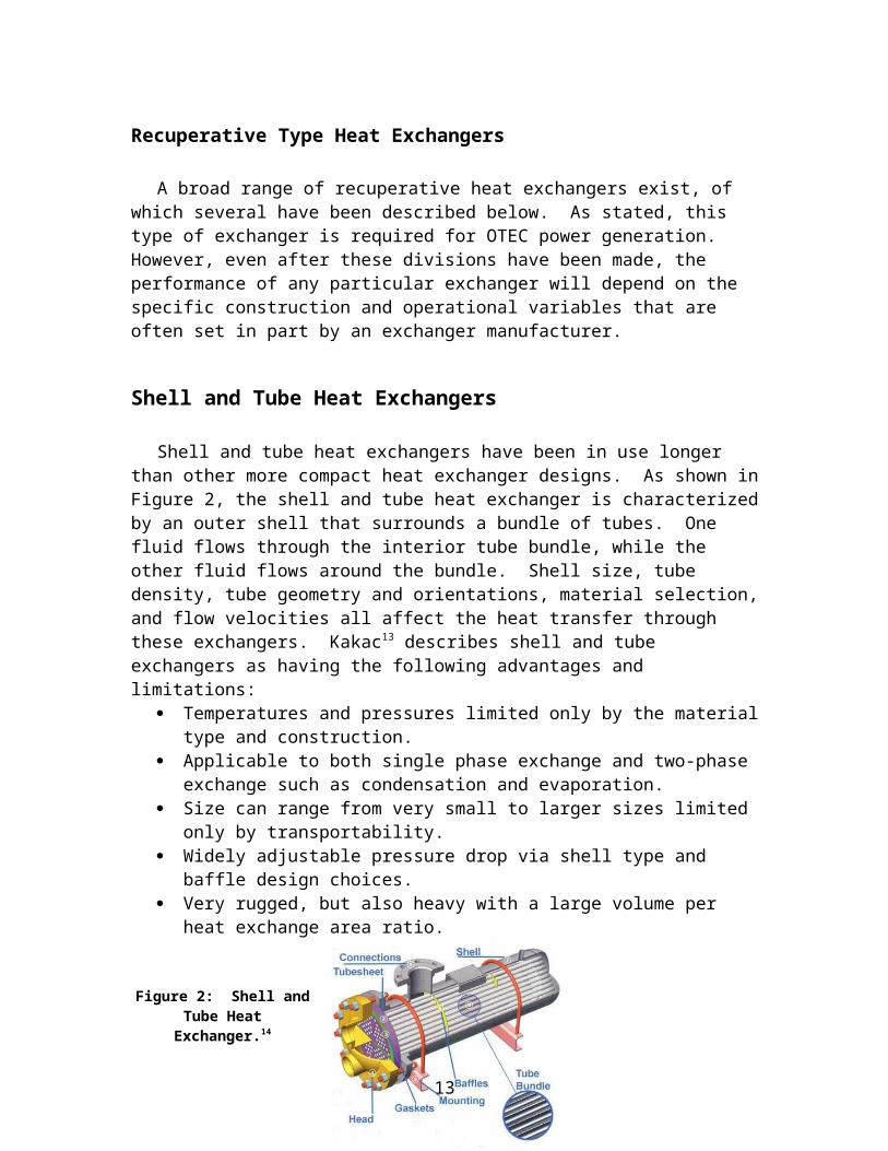
Shell and Tube Heat Exchangers
Shell and tube heat exchangers have been in use longer than other more compact heat exchanger designs. As shown in Figure 2, the shell and tube heat exchanger is characterized by an outer shell that surrounds a bundle of tubes. One fluid flows through the interior tube bundle, while the other fluid flows around the bundle. Shell size, tube density, tube geometry and orientations, material selection, and flow velocities all affect the heat transfer through these exchangers. Kakac13 describes shell and tube exchangers as having the following advantages and limitations:
Temperatures and pressures limited only by the material type and construction. Applicable to both single phase exchange and two-phase exchange such as
condensation and evaporation. Size can range from very small to larger sizes limited only by transportability. Widely adjustable pressure drop via shell type and baffle design choices. Very rugged, but also heavy with a large volume per heat exchange area ratio.
Figure 2: Shell and Tube Heat Exchanger.14
These heat exchangers were not initially considered a viable option for several reasons. First, the large surface-area-to-volume ratio requires a larger amount of floor area. Second, a significant reduction in heat transfer can occur due to biofouling for these exchangers, which increases maintenance cost and the required designed surface area. Finally, the relatively high weight that results from the increased volume is also undesirable for use on a plant ship.
13 Kakac, S (1991) “Boilers, Evaporators, and Condensers.” John Wiley & Sons Inc, New York, pp. 144.
9

Plate-and-frame
The plate-and-frame style heat exchanger is set up as shown in Figures 3 and 4. The two fluids enter the exchanger at the top and bottom of one end of the exchanger. Separated by plate gaskets, the fluids are able to exchange heat without contact.
Figure 3: Plate-and-frame heat exchanger (PHE)15
The size and number of plates depends upon the specific application. Large stacks of plates provide the active surface area for heat transfer. Perforated plate channels control the fluid flow along the plates and increase the turbulence of the flow. Turbulence increases the amount of convective heat transfer that can occur, which is an important part of the heat transfer in these exchangers. For large scale applications, like those found in OTEC power generation, plates can be up to about 5 meters in height and 2 meters in width, with hundreds of plates on a single frame.
18Figure 4: Flow through a PHE.16
Variables such as corrugation geometry, plate thickness, and flow velocities all greatly affect the performance of these exchangers. In addition, the flow pattern can either be single or multi-pass pattern. In a single pass, each flow passes the other liquid only once, while a multi pass flow runs the fluids past each plate in the heat exchanger. Figures 5 and 6 below illustrate this difference. For a low temperature application such as OTEC, a multi-pass pattern is generally recommended for maximum heat transfer. However, Hewitt suggests that multi-pass flows are sometimes difficult to implement for large exchangers.17
10

Figure 5: Single-pass and Multi-pass flow through a PHE.18
Figure 6: Multi-pass flow through a PHE.19
There are three main advantages to this type of heat exchanger style. First, it has a high level of heat transfer per unit area relative to the other exchangers. Second, the plate style lends well to scalability and minimizes the overall volume-to-area ratio. Third, biofouling is also reduced due to the relatively high turbulence in the flow. This reduces the need to compensate for fouling, further reducing the surface area required.
Although these advantages are very useful, there is also a very large frictional pressure loss due to the flow arrangement, which increases as more plates are added or the plate area is increased. The maximum allowable pressure of current plate exchangers is also significantly lower than those possible with shell and tube exchangers.
11

Matrix/Plate-Fin Heat Exchangers
This type of exchanger uses plate stacks similar to those found in plate exchangers. Unlike plate-and-frame exchangers, where plates separate fluids, flow channels within each plate separate the two fluids. As shown in Figure 7, folded sheet metal are soldered or brazed between plates to create a cross-flow matrix. These plates are stacked in a setup similar to plate exchangers with heat exchange occurring in the flow passages. Like plate heat exchangers, these design are quite compact and of interest for this project. However, because it cannot be cleaned, it is restricted to clean fluids like cold seawater and ammonia.
Figure 7: Matrix/Plate-Fin Heat Exchanger Plates
12
Existing Technology
A large number of companies manufacture heat exchangers. Of these, those who advertised non-metallic heat exchangers were contacted regarding heat exchanger applications under OTEC conditions. A number of individuals from these and other companies were also interviewed with regards to the implementation of these heat exchangers. A focused search for manufacturers of thermally conductive plastics was also conducted. This extensive survey of current technology comprised the bulk of the research period. The following sections are compilations of this research.
Extensive literature is available on heat exchanger design, which was an important supplement to the information provided by OCEES. While OCEES provided information relevant to their designs, much of this knowledge falls outside the scope of their particular expertise as end-users of heat exchanger technology. This literature was primarily found from the University of Hawai`i Hamilton Library, various online sources, and communications with heat exchanger engineers and manufacturers.
In contrast to shell and tube manufacturers, compact heat exchanger manufacturers do not offer the same level of customization. This is due to the high capital cost of developing these compact designs. With a number of completed designs, manufacturers do not build customized exchangers for a client’s particular application. Instead, they tailor the variables of flow rate and number of exchanger units to achieve the required heat exchange duty. For this reason, many manufacturers do not have products that can effectively target the conditions of an OTEC system.
The following companies advertise plastic heat exchangers: Calorplast (subsidiary of PlasticMagen) and George-Fischer (United
States supplier of Calorplast products) AB Segerfrod SEC Heat Exchangers Protensive Engineering Wastech Engineering
Calorplast Polypropylene Heat Exchanger
With the exception of Calorplast, all of the companies above declined to quote a price or exchanger estimate for OTEC conditions. The following polymer exchanger was sited by Calorplast as the best model available for an OTEC application. Shown in Figure 8, the heat exchanger is a hybrid type exchanger, combining properties from shell-and-tube exchangers, plate-and-frame exchangers, and matrix exchangers. Polypropylene tubes are bundled into plates, which are stacked in a column surrounded by an outer shell. Ammonia flows through these plates, and seawater flows down the column across each plate. George-Fischer was unable to provide an explanation for the design choice of tube-plates versus plate-and-frame construction.
13

OCEES International’s proposed 10 MW plant requires roughly 3.5 million lb/h of warm water and 4 million lb/h of cold seawater, which is a huge amount of water. Each heat exchange unit has an upper limit on the flow velocity through the exchanger due to the mechanical strength of the tube-plates. This limits the heat transfer duty of each exchanger. To accommodate the large volume flow through these exchangers, George-Fischer quoted roughly 4000 units for the condensation duty alone, which compared to the 50 titanium units in the current design. With a unit cost of $9000 per exchanger, this was roughly 50% more expensive that the quoted cost of titanium exchangers. The quoted cost of evaporators nearly doubled the cost of titanium heat exchangers. Cost estimates were based upon quoted cost of titanium heat exchangers and communications with George-Fischer, the American supplier of Calorplast heat exchangers.
Figure 8: Calorplast Polypropylene Polymer Heat Exchanger.20
In addition to high costs, the floor area required by these exchangers was also greater than their titanium counterparts. At best, three of these exchangers would occupy the floor space of a single titanium unit. With a required floor are nearly two orders of magnitude larger than titanium units, the use of these exchangers on a floating plant-ship would require a revaluation of the overall system design. Pressure drop is also an important factor in calculating the power required for pumping, and, of course, a lower pumping cost is desirable. However, pressure drop estimates were not provided by George-Fischer. For these reasons, communication with George-Fischer indicated that the current state of polymer heat exchangers is not competitive with metal heat exchangers, even for cost reasons alone.
The lack of manufacturers able to meet the needs of OCEES prompted a preliminary evaluation of polymers for use in heat exchangers. The major considerations for this particular evaluation were as follows: thermodynamic analysis and sizing, mechanical stress analysis for operating pressures, and material selection. Assumptions
14

were made in order to simplify the design process since designing a novel type of exchanger was certainly outside the scope of this project. Initially, a plate-and-frame type was assumed because the current design calls for this type of compact heat exchanger.
Elements of Heat Exchanger Design and Evaluation
Publicly available information regarding heat exchanger design often assumes that a heat exchanger is being purchased rather than designed by the reader. Much of the design process is proprietary, and, according to communications with one heat exchanger manufacturer, much of the design and optimization is done by building and testing exchangers rather than designing them on paper or with finite element modeling software. While the thermodynamic equations in the next section are all from publicly available literature focused on heat exchanger design, the sections on stress analysis and material choice are not based on recommendations specifically focused on heat exchanger design.
Thermodynamics of Heat Exchanger Design
Heat exchangers used in power generation have two major thermodynamic processes in action: heat transfer and liquid/gas phase changes. Conductive heat transfer occurs through the heat exchanger material, and convective heat transfer occurs within the working fluid and heat source. This heat transfer causes evaporation and condensation of the ammonia working fluid, driving the heat engine and producing electrical power.
The following information is of key importance: mass flow rates through the system, the fluid type, fluid properties, inlet and outlet temperatures, working pressures, pumping requirements, total heat exchange duty, and allowable pressure drops. If a design is already present, then the material properties and heat transfer area are also important to know beforehand. Otherwise, these will be determined as specified by the design process.
Heat Transfer Equations
Enthalpy:
Neglecting heat transfer to or from the environment, heat exchangers essentially exchange enthalpy between the two fluids. Enthalpy is defined as the internal energy of the system plus the work done on the environment by the system:
(3)
where U is the internal energy of the system, and p is pressure and V is volume. The enthalpy of the seawater in this system is straightforwardly dependent upon temperature
15

change. When no phase change occurs (i.e. constant volume temperature change), enthalpy also helps to measure heat transfer of a heat exchanger:
(4)while a phase change does occur in the ammonia-water side of the exchangers, no phase change occurs on the seawater sides of these exchangers. Therefore, this can be applied to the seawater side of the exchanger.
In general terms, , the desired heat transfer rate for a fluid in a system, can be specified by the following equation:
(5)
where is the mass flow rate, Cp is the specific heat of the fluid, and is the change in temperature of the fluid. Given a desired seawater temperature change and flow rate, the heat exchange transfer duty can be specified.
After determining, the amount of heat transfer duty, the size of the heat exchanger must be specified. The amount of heat transfer performed by a specific heat exchanger depends on the design of the heat exchanger, the temperature difference between the fluids, its overall heat transfer rate, and active heat-transfer surface area.
As the fluids pass over the heat exchanger, the temperature difference between the two fluids will change. Thus, the flow that creates the temperature gradient through which transfer occurs is very important. There are three types of conventional flow types employed:
Counter-flow: Fluids flow in directions opposite each other throughout. When the specific heat capacities of the fluids are constant, it can be shown that the temperature gradient between them will be linear. This flow type is often the most desirable because it maximizes the average temperature difference between the fluids. In turn, this maximizes the heat transfer rate between the two fluids per surface area of transfer.
Cross-flow: The two flows run perpendicular to one another and exchange heat at their intersection. This flow type is primarily used when one of the two fluids undergoes a phase change (i.e. water to steam). The average temperature difference for this flow-type is greater than parallel flow but less than in counter-flow.
Parallel Flow: The flows run in the same direction, parallel to each other. The temperature difference, therefore, is minimized as the flows reach their exit point, which reduces the overall heat transfer rate. This is not desirable for OTEC since the temperature difference is very small.
While a counter-flow exchange is not always available, it is usually desirable to be as close to this as possible. The equation below, valid for all flow types, calculates the heat transfer duty and shows its dependence on U, the overall heat transfer coefficient, A,
16

the effective heat transfer area, ΔTLM, the log-mean temperature difference between the two fluids, and F, the correction factor for the flow type:
(6)
The correction factor, F, is unity for counter-flow arrangements and less than unity for other flow arrangements. The log-mean temperature difference is calculated from the following equations and assumes an idealized heat transfer between the hot and cold fluids:
(7)
where is the difference between the warm inlet and cold outlet and is the difference between the warm outlet and cold inlet.
The overall heat transfer coefficient, U, is a function of the heat transfer coefficient of the heat exchanger material, fouling factors, and the convective heat transfer coefficients of the system (also known as skin or film coefficients).
(8)
(9)
where, hhs is the film coefficient of the hot side, hcs is the film coefficient of cold side, Rw is the wall resistance, Ff is the fouling factor, k is the thermal conductivity of the material, and t is the material thickness.
The fouling factor corrects for the loss of heat transfer due to fouling that will occur during operation. Bacteria and other micro-organisms can build-up on the surface of heat exchangers over time. This film can impede heat transfer and appears as the fouling factor. For plate heat exchangers the fouling factor is generally accepted to be very small (negligible) due to the high turbulence inherent in corrugated plate heat exchangers. The fouling factor for other heat exchangers depends greatly upon the fouling controls used, the cleanliness of the water, and the time between maintenance cleaning. Equation 5 shows that the wall resistance is fairly simple to calculate given material properties and wall thickness. For design purposes, however, wall thickness depends on design pressure, meaning that it will vary with the material’s strength and stiffness.
The film coefficients depend on the flow turbulence, velocity, fluid viscosity, and temperature, which further complicates determining calculations for the heat transfer coefficient U. For the purpose of this report, the film coefficients were assumed to be determined by the heat exchanger geometry. Since no new heat exchanger dimensions and geometries were designed for this report, the film coefficients were assumed to be set
17

by pre-existing designs. Formulas for calculating film coefficients contain experimentally obtained coefficients. For this reason these equations are not within the scope of this report.
While determining the film coefficient is certainly beyond the scope of this report, it was hoped that a stress analysis might reveal the necessary thickness of these exchangers. Once the thickness is determined, the film coefficients and the effects of fluid flow might be further explored in future work.
Performance Variables:
Plate-and-frame Heat Exchangers
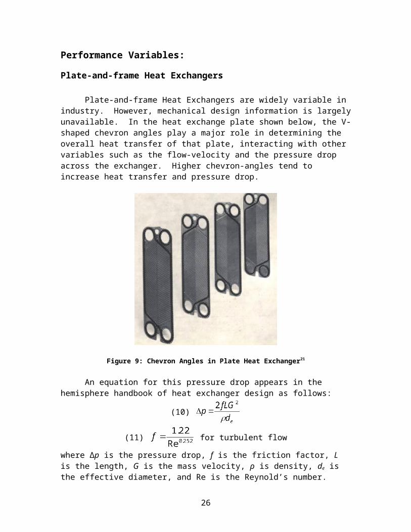
Plate-and-frame Heat Exchangers are widely variable in industry. However, mechanical design information is largely unavailable. In the heat exchange plate shown below, the V-shaped chevron angles play a major role in determining the overall heat transfer of that plate, interacting with other variables such as the flow-velocity and the pressure drop across the exchanger. Higher chevron-angles tend to increase heat transfer and pressure drop.
Figure 9: Chevron Angles in Plate Heat Exchanger21
An equation for this pressure drop appears in the hemisphere handbook of heat exchanger design as follows:
(10)
(11) for turbulent flow
18

where Δp is the pressure drop, f is the friction factor, L is the length, G is the mass velocity, ρ is density, de is the effective diameter, and Re is the Reynold’s number. This is approximately true for plate heat exchangers. Notice that the pressure drop, a variable that affects pumping costs, is directly affected by flow velocity through the Reynold’s number. An increased flow velocity increases the Reynold’s number and pressure drop. At the same time, this increased flow velocity increases the turbulence of the flow, greatly reducing the film resistance of the fluid. Thus, manipulating even one variable, flow velocity has tradeoffs. While the use of these equations is not understood, it does demonstrate the dependence of exchanger performance upon a large number of highly interdependent variables.
Shell and Tube Exchangers
Shah also indicates that heat exchangers are designed according to ASME code Section VIII, Div. 1. They give the required thickness of a heat exchanger tube as follows:
(10)
where t is the thickness of the shell, p is the pressure, r is the inner radius of the shell, S is the maximum yield stress of the material, and E is its elastic modulus.
As this and other equations demonstrate, shell and tube exchangers have been documented to a much larger degree. Equations are readily available for much of their design. However, according to, Shah, the average plate exchanger will require 1/2 to 1/3 of the surface area required by an equivalent shell and tube exchanger and 1/6 of its weight. Therefore, while literature is much more widely available, the increased surface area requirements and fouling concerns deterred further exploration.22
Matrix Exchangers
One source indicates that matrix exchangers can be used in OTEC applications. However, this source indicated that the plate thickness required for these polymer exchangers is 10 mm in thickness, or roughly 10 times the thickness of metal plate heat exchangers. This suggests that matrix exchangers cannot compete in terms of required floor space.23 Further work in this area of exchangers might lead to a heat exchanger capable of performing heat transfer duty even if floor area would be greater.
19

Material selection
Initially, the question of material selection was left to the manufacturers. A material might be inexpensive and be ideal on according to a data sheet. However, if one cannot properly process it, none of this matters. Thus, any material would require significant experimental testing prior to being considered. However, once it was established that currently available exchangers are not competitive with titanium, material selection was considered. Material selection for a particular heat exchanger application comes down to fundamental questions of material properties. Does the material have a sufficient stiffness (elastic modulus) to support the working pressure of the setup? Does the material have a sufficient ductility to withstand operation, transportation, and assembly? Does the material have sufficient toughness to endure long-term load without significant creep and stress fracturing? Does the material yield to corrosion in a seawater and ammonia environment? If so, what is the timeline for critical failure? If corrosion occurs, what kind of corrosion occurs? Is the heat exchanger system susceptible to biofouling? How does this affect corrosion? Can these problems be prevented or mitigated with maintenance or other care? Is the material smooth or rough? How does this affect frictional pressure drops and the turbulence necessary convective heat transfer? What are the added maintenance and lifecycle costs? How does material selection affect the overall size and mass of the device? What costs are implicit to different heat exchanger configurations?
Although there are an array of metal alloys that might replace titanium, the use of these materials in heat exchangers has been characterized to a great extent. Thus, finding polymer-based designs was seen as a novel concept worthy of research. A brief literature search and revealed the following information about polymers in general:
Challenges in Polymer Heat Exchangers
Higher susceptibility to fatigue stress and creep Relatively low elastic modulus and tensile strength compared with metals Low ductility (in some cases) Lower thermal conductivity relative to metals, especially without fillers or
additives. Lower melting points Possible permeability to pressurized ammonia Manufacturability No current manufacturers of feasible products (high cost of development) Possible limitations in extrusion geometries. Size limitations for injection
molding.
20

Advantages of Polymers Relative low cost of raw materials (and possibly in processing) Possibility of longer lifecycle due to high chemical and corrosion resistance Lighter for transport Higher availability of raw materials New materials constantly being developed
Chemistry: Metallic Corrosion vs. Polymer Corrosion
The current OCEES system design for a platform-based offshore power plant calls for the use of titanium plate heat exchangers. Understanding the reasoning for this choice is important for moving to a new material selection. As literature and communication with heat exchanger manufacturers suggests, the most common choice for the given application is titanium. As a metal, titanium has an extremely impressive resistance to seawater corrosion. An oxide layer which forms on the surface of titanium provides a particularly corrosion-resistant coating for the heat exchanger surface. In fact, when compared to steels and other metals, titanium is the metal of choice for corrosion resistance in a seawater environment. However, other material properties also come into play. For example, titanium has a lower thermal conductivity (measured in W/m K) than other metals. On the other hand, it has a high elastic modulus, which reduces the required thickness and increases the overall heat transfer coefficient. One of the major factors working against titanium is its relatively high cost per weight, a number that has recently increased under high demand and low availability.
Literature also suggests that various steel alloys (SMO 254, Seacure, SS316, SS304), aluminum alloys, Hastelloy, Incoloy, and other alloys can also resist seawater corrosion to some degree. Further investigation would be required to evaluate the use of these metals. However, this was beyond the scope of this report. While the price of raw materials would certainly affect the price of these exchangers, manufacturers must be contacted directly for cost quote. Communications with heat exchanger manufacturers suggested that carbon and graphite composite materials are considerably more expensive than titanium and, for that reason, are not considered here.
Metallic Corrosion:
There are four major types of corrosion in metals: Crevice corrosion, spot corrosion, and stress-corrosion cracking. The details of these corrosion types were not within the scope of this report. However, they do occur in all metals, including titanium, under different operating conditions. This is an important distinction between metals and polymers. While metals can resist seawater corrosion, in comparison, polymers are not adversely affected by seawater exposure.
21

Polymers:
A polymer is defined as any ‘large organic molecule formed by combining many smaller molecules (monomers) in a regular pattern.’ This definition, therefore, encompasses many unique materials. In general, however, polymers are known to have excellent chemical and corrosion resistance. In contrast, the strength and thermal conductivity of polymers are significantly lower than metals. Therefore, the major concern with plastics is not their corrosion resistance.
The following polymers have been cited as both commonly available and resistant to seawater and ammonia environments: high-density-polyethylene (HDPE), polypropylene (PP), and polyphenylene sulfide (Ryton, PPS).
After contacting manufacturers of plastic and polymer heat exchangers, it was found that most of their products were produced by plastics with very low thermal conductivity. As mentioned previously, this low thermal conductivity is a general property in plastics. Due in part to the low thermal conductivity of the plastics, these exchangers were found to have a footprint larger than desired for the limited floor area application of the off-shore OTEC facility. Thus, a search was conducted for thermally conductive plastics. From this list, plastics with good chemical and corrosion resistance were identified.
CoolPolymers, a polymer manufacturer, produces the following thermally conductive plastics recommended for use in heat exchangers: E2, E1201, E5101, D5018, and D1202. Please see Appendix B for material properties of their base polymers and their website, www.coolpolymers.com, for further details. The major consideration for these plastics was a thermal conductivity that was much higher than the other plastics. Polypropylene sulfide (PPS), is normally advertised as having a thermal conductivity of about 0.3 W/mK. In contrast, E5101, one of the PPS polymers offered by CoolPolymers has a thermal conductivity of 20 W/mK. When asked about how they achieved high levels of conductivity, they mentioned that their fillers were carbon-based but nothing else. Since the stiffness of these plastics is much lower than that of titanium, any design using plastics will likely require a higher volume of material than an equivalent titanium design.
As these polymers have a wide range of material properties, any recommendations beyond this list would require a mechanical stress analysis and/or further information regarding specific polymer manufacturability. Stress analysis has direct ties to the thermodynamic analysis because the material thickness is directly related to the overall heat transfer coefficient (see Equations 8 and 9).
Since very little experimental data was available (most is proprietary data held by large manufacturers), it was assumed that heat exchangers were structurally designed to maximize heat transfer. That is, the plate thickness depends on the maximum stress at any given point rather than on manufacturability or other variables. Communication with
22

a titanium heat exchanger manufacturer suggested, however, that the minimum plate thickness might also be a function of manufacturability. While titanium Grade 1 has a fairly high ductility, cold-working limitations do exist that might be another factor in their thickness.
Still, since the maximum stress load at any point depends upon the base load of pressure on the entire plate, the thickness is indirectly a function of the pressure differential between the plate heat exchangers.
Stress Analysis
Comprehensive heat exchanger design requires extensive manufacturing and pressure-testing. This is a highly technical and capital intensive process. As a literature search revealed, much of the information regarding the design process for heat exchangers is highly proprietary. Thus, only a preliminary design is possible with the publicly available information. Therefore, one important measure of material compatibility with a particular heat exchanger design is its maximum stress tolerance. Using material properties from data sheets, this was one method for screening materials.
Titanium Grade 1 is a highly ductile for of titanium that is ideal for the cold-work plate pressing that occurs during manufacturing. Not all metal alloys are capable of undergoing this process.
Due to the variation and complexity of geometries present in various corrugated plate heat exchangers, a stress analysis from generic plate geometry was unavailable. Chevron corrugations touch at the crest of each corrugation, which means the cylindrical geometry is a good estimation of the setup. The following equation defines hoop stress, which relates plate thickness to stress:
(10)
where p is the design pressure, r is the radius of the cylinder, and t is the thickness of the material. To test whether this was valid, the titanium heat exchanger was assumed. The design pressure of 150 psi and the yield strength of titanium were both known with certainty. However, the choice to model this as hoop stress failure was only a guess based upon the plate exchanger setup. The chevron geometry and exchanger setup only allowed an estimation of r, the radius, at 3.3 mm or about the depth of the corrugation.
Solving this equation for thickness, t, yields a value of 0.01-0.03 mm, less than 5% the 0.7 mm of thickness in the quoted plates (See Appendix A). This estimation, therefore, seems to be completely inaccurate. This is not completely unexpected. Hoop stress is derived for a tube or other cylindrical pressure vessel. Because the corrugations are not welded tubes, this type of stress analysis would have provided an estimate at best. Also, stress analysis in a real system would not necessarily show maximum stresses in intuitive areas of the system.
23

Roark and Young calculate the stress for a simply supported flat plate with a uniform stress load through the finite difference method:
(11) ,
where the coefficient β (ranging from 0.2874-0.75) is defined by the ratio of length (a) vs. width (b). In this case, the ratio a/b is 3.72 (186 inches / 50 inches), for a coefficient of about 0.73 (See Roark’s and Young).24 With the uniform distributed load, q, and the thickness, t, also known, it is a simple calculation to show that the maximum stress in this scenario is 25 GPa, which is well above both the ultimate and yield stress of titanium Grade 1.
As this shows, failure of PHE plates cannot be accurately estimated by yield stress of a flat plate. Since plates touch at corrugation points, the plates can support each other. Thus, when pressed and tested, these exchangers produce a certain stress.
Based upon the inaccuracies of the estimations, it was concluded an independent stress analysis would be necessary. Because the heat exchanger design process is a proprietary design process, the extent to which proven design capabilities are available is limited. An analysis was attempted using ABAQUS, a finite-element modeling program. However, modeling with this software was beyond the ability of this author, and dimensional schematics were unavailable to provide accurate physical models. In addition to this, validating the model was not possible given the lack of a heat exchanger to test. As a result of these stress analysis attempts, no independent estimation of the required increase in plate thickness was found. Further work is required in order to determine this important result.
Results
Pending a confident estimation of required thickness increases, the effect of plate thickness was evaluated from the heat transfer equations in the previous section. Back-solving for the overall heat transfer coefficient of the quoted titanium evaporator PHE was useful because it gave a ballpark estimate for the effect that thickness would have on the heat transfer. The cited heat transfer duty of the exchanger, the log-mean-temperature difference of the exchanger (calculated from Equation 7), and the active area were all used with Equation 6 to calculate the overall heat transfer coefficient. Equations 8 and 9 were then used to calculate a value for the sum of the other factors affecting the overall
heat transfer coefficient, . This showed that the wall resistance of about
0.000043W/m2K was only a small part of the overall heat transfer coefficient when compared to the resistance due to the other factors (0.019W/m2K). (See Appendix A for calculations).
Because of this, it was hoped that thermally conductive polymers with a heat transfer coefficient of 20 W/mK would play similarly small roles in heat transfer if the
24

system design was the same. It was assumed that the other factors would
be about the same for a similarly constructed polymer exchanger. While this assumption is a large one (given that film coefficients depend upon the smoothness of the material and many other factors), if it is somewhat valid, it shows that thermally conductive polymers can play a major role in increasing the effectiveness of polymer heat exchangers. A new U value was calculated based upon a 10 mm thick polymer wall with and without the added thermal conductivity. For a thermally conductive polymer (E5101 PPS), the required area for heat transfer increased by only 2.3%. This was amazing when compared to a 167% increase in the required area when calculated for non-thermally conductive PPS. This shows, therefore, that the thickness of these plastics will not greatly affect the required heat transfer surface area. However, they would certainly increase the total amount of floor area required.
If it is possible to assume a similar linear dependence of stress on thickness, then the plastic heat exchangers would need to be over twice the thickness of the titanium heat exchangers assuming a one-to-one dependence based on their failure criterion, as demonstrated in Table 1.
Material: TitaniumE2 (LCP)
E1201 (PP)
E5101 (PPS)
D5108 (PPS)
D1202 (PP)
Tensile strength [MPa] (For Plastics tensile strength/flexural strength 170 75/135 20/35 45/70 36/68 25/43Thermal Conductivity [W/mK] 16 20 10 20 10 5Modulus GPa (For Plastics tensile/flexural) 105 20/32 3.65/4.2 13.5 12/19 5.2/6
Table 10: Material Properties Comparison Chart for Titanium and Polymers
However, for footprint evaluations, the variation of 1 mm per plate changes the overall attractiveness greatly. In a set of 50 heat exchangers, each unit has between 70 and 350 plates. Therefore, an increase in plate thickness of 1 mm, can dramatically increase the footprint of the heat exchanger system by 5% for the evaporators and 0.75% for the condensers (See Appendix A). As this cost is measured in millions of dollars, unless these exchangers can be delivered with minimal increases in plate thickness, the cost savings could be minimal for use on a plant-ship.
When compared to a metal heat exchanger of the same configurations, polymer exchangers must certainly be thicker to handle the same design pressure. This thickness increase is unacceptable for plant-ship use due to floor area restrictions. However, if polymers are used in systems without the same floor area requirements or high design pressures, then they might compete very well with titanium. This led to an investigation of Seawater District Cooling. In HVAC cooling, floor area is not necessarily as expensive as it is on a floating plant (where OCEES cites floor area as roughly as expensive as the heat exchanger itself). Therefore, thicker plates might still be competitive due to lower unit cost.
25
Seawater District Cooling
OCEES International is also interested in reducing cost for heat exchangers in Seawater District Cooling (SDC) projects. In this case, cold seawater cools fresh water, which is then delivered to a larger system. Also, only one recuperative heat exchanger system is required with a pressure differential that is not necessarily as large. Since the cold water is in a cold loop, it can be shown that the pressure differential between the two liquids is simply the hydrostatic pressure required to pump the fresh water through its highest point of potential energy.
Thus, pressure, p, becomes a function of building height:
where, ρ is the fluid density (1000 kg/m3), g is the gravitational constant of acceleration, and h is the height of the building.
By the calculation below, a building 100 m tall (33 stories) would have a hydrostatic pressure of 142.3 psi, which is close to 150 psi.
Buildings that are under this height would be ideal for plastics because of reduced strength requirements. A lower design pressure simultaneously reduces the necessary surface are and material thickness. A tradeoff with increased pumping requirements would therefore be involved for a pressure reduction valve at the fresh water side of the pipe. Of course, if floor area for the exchangers is not a problem, then the exchangers might be very well suited for even high-pressure applications. As was shown in the previous section, it might be possible for thermally conductive plastics to perform the same heat transfer duty with only a slight increase in heat transfer. This would reduce an increase in the pressure drop that would otherwise occur (as Equation 10 shows it depends on the length of fluid travel). Further research into low-pressure polymer heat exchangers would be of great interest for SDC applications.
26

Brief Analysis of Cost SavingsThe following is a brief calculation of the cost per kilowatt-hour of producing
electricity at a proposed 10 MW power plant with a total capital cost of about 150 million dollars. The quoted cost of the heat exchanger is about 44 million dollars US with an annualized maintenance cost of about 1 million dollars. Assuming a 90% availability of electricity and an interest rate of 7%, Figure 11 shows that the cost of producing electricity is $0.196 /kwh (See Appendix A for calculations). While no savings have yet been projected due to these exchangers, it can be shown that a reduction in the capital cost of this portion of the system can significantly affect the project’s bottom line by $0.02/kwh for a capital cost reduction of 14 million dollars and a 50% reduction in annualized maintenance costs. This shows a significant incentive to investigate this further. With regard to Calorplast exchangers, the final row of Figure 11 shows that even if no maintenance costs are required, this system increases total cost by nearly $0.01/kWh
Changes in Capital Cost (in
millions of dollars)
Changes in maintenance
Cost (Hundreds
of thousands)
Changes in $/kWh
-1 0 -0.0010 -1 -0.001
-1 -1 -0.002-14 10 -0.00210 0 0.01110 -5 0.0050 -5 -0.006
-14 -5 -0.02140 -10 0.009
Figure 11: Chart of estimated cost savings chart as dictated by changes in maintenance and capital costs
There has been no indication as to whether any cost savings are possible because there is no way to estimate the total cost of a heat exchanger. Production costs are unknown. Lifecycle times are not possible without a testable design. Material costs depend on the amount of raw material required and the type of material.
27

Conclusions
Current polymer heat exchangers do not meet the design constraints of OTEC plant-ship power generation.
Even with a thermal conductivity equivalent to that of titanium, the smaller mechanical strength of polymers does not warrant the replacement of titanium as heat exchange material unless floor area is not a constraint.
Polymers may be applicable in Seawater District Cooling applications if new thermally conductive polymers are used.
Future WorkPolymer strength is one of the major factors preventing the widespread use of
polymers in marine environments. It was thought that shell and tube designs would more readily adapt to polymer extrusion processing and polymer strength. Tubes more readily support the pressure of liquid ammonia used in OTEC power generation. While shell and tube designs are purported to use more space that plate and frame designs, this may be due to the negligible difference between plate thickness and tube thickness. In polymers, however, tubes can be made much thinner than plates. Thus, the space savings of a polymer heat exchanger may not be great relative to a shell and tube exchanger. These avenues should be explored further.
In addition, polymer plate-and-frame exchangers are not available on the current market. While this is discouraging, it seems that the compact nature of plate-and-frame construction should be further explored to any extent possible. Even with a greater thickness, the savings in weight and material costs could significantly increase the economic feasibility of an OTEC system. The following list specifically describes the necessary work required for a thorough evaluation of polymer exchangers:
Develop a mechanical stress and pressure drop prediction model for various heat exchanger designs using OTEC operating conditions.
Determine the effect of additives on extrusion and injection molding processing. Also determine their affects on the exchanger lifecycle, manufacturability, and cost.
Consider low-cost methods for increasing overall mechanical strength without adversely affecting increased thermal conductivity and maintaining high levels of corrosion-resistance and chemical compatibility.
Use this and other information to develop thorough a metric for evaluating potential heat exchanger materials.
Develop and test a low-cost polymer exchanger. Investigate the use of polymer heat exchangers in SDC applications.
28

Further Social Context and Impact
The social impact of OTEC technology goes beyond the ability to produce a consistent source of renewable, low-impact, cost-effective base-load power. Freshwater, aquaculture, and seawater air-conditioning are all very important co-products of the cold-seawater available downstream from an OTEC plant. As the population increases, the demand for all of these will continue to increase, further taxing the oceans, aquifers, and energy supplies. Thus, providing these resources through renewable sources might provide invaluable social and economic benefits to the populations near these facilities.
Natural Energy Laboratory of Hawai`i Authority (NELHA) Site Visit
NELHA, located in Kailua-Kona, is the site of proposed site of OCEES International’s 1 MW commercial power plant. The site was home to several of the research scale OTEC power plants, and currently hosts a large number of commercial and research tenants. The tenants engage in a number of endeavors including aquaculture (various fish, lobsters, seaweed, shrimp, clams, and algae) and the bottling of desalinated-deep-seawater. A 40-inch diameter cold-water pipe provides up to 13,400 gpm of cold-seawater.25 In fact the pipe, a section of which is pictured below, provides enough cold seawater to power a 1 MW OTEC power plant.
Figure 12: A Section of the HDPE pipe used to provide Cold-seawater to the NELHA facilityThe work done at NELHA provides a model for future OTEC developments
around the world. This could be particularly useful for island communities where freshwater supply is limited and fish and other marine life are parts of the staple diet.
29
Acknowledgements This paper describes work done under the supervision of Dr. Hans Jergen Krock,
Professor Emeritus at the University of Hawai`i, and the engineers at OCEES International. Headed by President Dr. Krock and Vice President Dr. Stephen K. Oney, OCEES International is a private engineering firm dedicated to commercializing OTEC technology. Engineers Todd Ericksen, Dave Smith, and Chris Looney were also vital resources during this time. I would like to thank Dr. Krock and all of the engineers at OCEES International for their support during the course of this project. Professor Peter N. Saeta from the Harvey Mudd Physics department was the faculty advisor during this project and was an invaluable resource throughout this project’s development. Special thanks to Harold Sipe of Wastech Engineering and Kris Obirek of George-Fischer for their insight regarding heat exchangers.
30

APPENDIX A: Calculations
Thermodynamic analysis of a titanium heat exchanger:Given parameters: Heat Transfer Duty (12,700,000 Watts), total active area (982 m2), and LMTD (calculated to be 257 Kelvins). Assume counter-current flow (F is 1)
Titanium wall resistance =
From Equation 9, the resistance due other factors =
From Equation 6, new total active area for a U value calculated with a 10 mm wall of PPS is:
For thermally conductive PPS:
For non-thermally conductive PPS:
This can be used to calculate the increase in active heat transfer area required:
For thermally conductive PPS,
For non-thermally conductive PPS,
This correlates to an increase of 2.3% of required area for thermally conductive plastics and a 167% increase in required area for non-thermally conductive plastics.
Hoop stress for a 3.3 mm plate exchanger channel depth: Given parameters: r = 3.3 mm, p = 150 psi = 1.034 MPa, σhoop 170 MPa, and t = unknown
,
Therefore, ,
where 2/3 of the yield stress was used as the hoop stress and 150 psi = 1.03421359 MPa.
31

Furthermore, according to ASME Section VIII Div. 1, the thickness for a thin shell is described by the following equation. Under OTEC operation conditions and a radius of 3.3 mm, a shell thickness of 0.03 mm is required.
Stress in a flat plate of 0.7 mm thickness (Roark’s and Young):
32

Required floor area for evaporators plate heat exchangers. Given the quoted designs, a 1 mm increase in plate thickness was assumed. According to OCEES’ design, the exchangers require 1 meter of added maintenance area around each pair of exchangers.
The current evaporator exchangers have a length of 186 inches (4.72 m) and a width of 50 inches (1.27 m). Therefore, the following equation determines the floor area required by two exchangers:
Thus, 50 units, or 25 pairs, will require 762 m2 of floor area. In the evaporator frame there are 340 plates. Assuming a 1 mm increase in plate width increases the frame width accordingly for the same number of plates, even assuming that more plates will be unnecessary, the length will be increased by 0.340 meters. The following calculation shows the necessary percent increase in floor area requirements.
As shown, the increase in floor area is 5% per additional 1 mm of plate thickness. Again, this assumes identical design and frame accommodations.
The condenser stack has a length of 286 inches (7.26 m) and a width of 50 inches (1.27 m). The stack contains 70 plates. A similar calculation for these setup reveals a 0.75% increase in floor area per 1 mm of increased plate thickness.
33

Economic Analysis:OTEC power costs – simplified calculation of current costs
Power 10 MWAvailability 90%
Capital Cost:Heat Exchangers: $ 44.00 All Others: $ 106.00
$ 150.00 $MInterest Rate 7%Booklife of Project 25 years
Capital Payment $12,871,577.58 HX Maintenance: $ 1,000,000.00 All others: $ 1,600,000.00 Operating Costs $ 2,600,000.00 $MCost of electricity $ 0.196 $/kWh
OTEC power costs - a simplified calculation of costs after a $1 million dollar savings in capital cost
Power 10MWAvailability 90%
Capital Cost:Heat Exchangers: $ 43.00 All Others: $ 106.00
$ 149.00 $MInterest Rate 7%Booklife of Project 25years
Capital Payment $12,785,767.07 HX Maintenance: $ 1,000,000.00 All others: $ 1,600,000.00 Operating Costs $ 2,600,000.00 $MCost of electricity $ 0.195 $/kWh
34

OTEC power costs - a simplified calculation of costs after a $100,000 saving in annualized maintenance costs
Power 10 MWAvailability 90%
Capital Cost:Heat Exchangers: $ 44.00 All Others: $ 106.00
$ 150.00 $MInterest Rate 7%Booklife of Project 25 years
Capital Payment $12,871,577.58 HX Maintenance: $ 900,000.00 All others: $ 1,600,000.00 Operating Costs $ 2,500,000.00 $MCost of electricity $ 0.195 $/kWh
OTEC power costs - a simplified calculation of costs after both a $1 million dollar capital cost saving and a $100,000 saving in annualized maintenance costs
Power 10MWAvailability 90%
Capital Cost:Heat Exchangers: $ 43.00 All Others: $ 106.00
$ 149.00 $MInterest Rate 7%Booklife of Project 25years
Capital Payment $12,785,767.07 HX Maintenance: $ 900,000.00 All others: $ 1,600,000.00 Operating Costs $ 2,500,000.00 $MCost of electricity $ 0.194 $/kWh
35

Chart of changes in cost savings:Changes in
Capital Cost (in
millions of dollars)
Changes in maintenance
Cost (Hundreds
of thousands)
Changes in $/kwh
-1 0 -0.0010 -1 -0.001
-1 -1 -0.002-14 10 -0.00210 0 0.01110 -5 0.0050 -5 -0.006
-14 -5 -0.02140 -10 0.009
Note that the final row, showing an increase of $40 million in capital costs without maintenance costs reflect the possibility of using Calorplast heat exchangers. Conversations with George-Fischer indicate that maintenance costs for these exchangers over their expected lifetime could be greatly reduced. If this is true, these exchangers might compete with a more titanium heat exchanger.
36

APPENDIX B: Material Property Data Sheets
Material Properties Comparison Chart:
Material: TitaniumE2 (LCP)
E1201 (PP)
E5101 (PPS)
D5108 (PPS)
D1202 (PP)
Tensile strength [MPa] (For Plastics tensile strength/flexural strength 170 75/135 20/35 45/70 36/68 25/43Thermal Conductivity [W/mK] 16 20 10 20 10 5Modulus GPa (For Plastics tensile/flexural) 105 20/32 3.65/4.2 13.5 12/19 5.2/6
Please see <http://www.coolpolymers.com> for complete material property data sheets for E2, E1201, E5101, D5018, and D1202. Data sheets are available in pdf format.
37

Material Properties: Titanium, Extruded Polypropylene, Extruded High-Density Polyethylene, Extruded Polyphenylene Sulfide
See MatWeb (http://www.matweb.com) for complete data sheets.
MatWeb Data Sheet
Titanium Grade 1SubCat: Titanium Alloy, Nonferrous Metal, Unalloyed/Modified Titanium, MetalMaterial Notes:Information provided by Allvac and the references.
Applications: Airframe components, cryogenic vessels, heat exchangers, CPI equipment, condenser tubing, pickling baskets.
Properties Value Min MaxPhysicalDensity, g/cc 4.51 -- --
MechanicalHardness, Brinell 120 -- --Hardness, Knoop 132 -- --Hardness, Rockwell B 70 -- --Hardness, Vickers 122 -- --Tensile Strength, Ultimate, MPa 240 -- --Tensile Strength, Yield, MPa -- f 310Elongation at Break, % 24 -- --Reduction of Area, % 35 -- --Modulus of Elasticity, GPa 105 -- --Compressive Modulus, GPa 110 -- --Poissons Ratio 0.37 -- --Charpy Impact, J 310 -- --Shear Modulus, GPa 45 -- --
ThermalHeat of Fusion, J/g 325 -- --CTE, linear 20°C, µm/m-°C 8.6 -- --CTE, linear 250°C, µm/m-°C 9.2 -- --CTE, linear 500°C, µm/m-°C 9.7 -- --Specific Heat Capacity, J/g-°C 0.52 -- --Thermal Conductivity, W/m-K 16 -- --Melting Point, °C -- -- 1670Liquidus, °C 1670 -- --Beta Transus, °C 888 -- --
38

MatWeb Data Sheet
Overview - Polypropylene, Extrusion GradeKeyWords:PP; Plastics, PolymersSubCat: Polypropylene, Thermoplastic, Polymer
Properties Value Min MaxPhysicalDensity, g/cc -- 0.895 0.912Water Absorption, % 0.01 -- --Moisture Vapor Transmission, cc-mm/m²-24hr-atm 14 -- --Linear Mold Shrinkage, cm/cm -- 0.015 0.017Melt Flow, g/10 min -- 0.47 350
MechanicalHardness, Rockwell R -- 80 104Hardness, Shore D -- 72 81Tensile Strength, Ultimate, MPa -- 20.7 460Tensile Strength, Yield, MPa -- 28 39Elongation at Break, % -- 8 540Elongation at Yield, % -- 8 13Tensile Modulus, GPa -- 1.515 1.725Flexural Modulus, GPa -- 0.93 2.068Secant Modulus, GPa 0.48 -- --Izod Impact, Notched, J/cm -- 0.21 1.6Izod Impact, Unnotched, J/cm -- 9 15.9Izod Impact, Unnotched Low Temp, J/cm 5.3 -- --Gardner Impact, J -- 1.7 28Seal Strength, g/25 mm 200 -- --
ThermalCTE, linear 20°C, µm/m-°C 100 -- --Melting Point, °C -- 134 165Maximum Service Temperature, Air, °C -- 65 124Deflection Temperature at 0.46 MPa (66 psi), °C -- 82 124Deflection Temperature at 1.8 MPa (264 psi), °C 63 -- --Flammability, UL94 HB -- --
39

MatWeb Data SheetOverview - High Density Polyethylene (HDPE), Extruded
KeyWords:Plastics, PolymersSubCat: Polyethylene, Thermoplastic, HDPE, Polymer
Properties Value Min MaxPhysicalDensity, g/cc -- 0.936 0.962Apparent Bulk Density, g/cc -- 0.58 0.61Water Absorption, % 0.01 -- --Moisture Vapor Transmission, cc-mm/m²-24hr-atm 0.38 -- --Environmental Stress Crack Resistance, hour -- 10 5000Melt Flow, g/10 min -- 0.14 13
MechanicalHardness, Shore D -- 58 65Tensile Strength, Ultimate, MPa -- 24 45Tensile Strength, Yield, MPa -- 15 30Elongation at Break, % -- 500 1000Tensile Modulus, GPa -- 0.8 0.99Flexural Modulus, GPa -- 0.5 1.52Izod Impact, Notched, J/cm -- 0.8 7.5Tensile Impact Strength, kJ/m² -- 320 480Coefficient of Friction 0.28 -- --
ElectricalElectrical Resistivity, ohm-cm 1.00E+17 -- --Surface Resistance, ohm 1.00E+17 -- --Dielectric Constant 2.3 -- --Dissipation Factor -- 0.0001 0.0005
ThermalCTE, linear 20°C, µm/m-°C 140 -- --Melting Point, °C -- 124 131Vicat Softening Point, °C -- 108 129Brittleness Temperature, °C -- -100 -70
ProcessingProcessing Temperature, °C -- 180 315
40

MatWeb Data Sheet
Overview - Polyphenylene Sulfide (PPS), Unreinforced, Extruded
KeyWords:Plastics, PolymersSubCat: Polyphenylene Sulfide, Thermoplastic, Polymer
Properties Value Min MaxPhysicalDensity, g/cc -- 1.35 1.43Water Absorption, % -- 0.01 0.02Moisture Absorption at Equilibrium, % 0.03 -- --Linear Mold Shrinkage, cm/cm 0.01 -- --
MechanicalHardness, Rockwell M -- 84 95Hardness, Rockwell R -- 120 125Hardness, Shore D 85 -- --Tensile Strength, Ultimate, MPa -- 28 93Elongation at Break, % -- 0.7 15Tensile Modulus, GPa -- 3.4 4.3Flexural Modulus, GPa -- 3.7 4Flexural Yield Strength, MPa -- 52 145Compressive Yield Strength, MPa -- 41 148Compressive Modulus, GPa 3 -- --Shear Strength, MPa 62 -- --Izod Impact, Notched, J/cm -- 0.1 0.75Izod Impact, Unnotched, J/cm 0.5 -- --Coefficient of Friction -- 0.16 0.4K Factor (Wear Factor) -- 75 999Limiting Pressure Velocity, MPa-m/sec -- 0.11 0.7
ElectricalElectrical Resistivity, ohm-cm -- 1.00E+15 1.00E+16Dielectric Constant -- 3 3.1Dielectric Strength, kV/mm -- 15 21.3Dissipation Factor -- 0.0009 0.0013Arc Resistance, sec 20 -- --
ThermalCTE, linear 20°C, µm/m-°C -- 49 59Thermal Conductivity, W/m-K -- 0.29 0.3Melting Point, °C -- 280 282Maximum Service Temperature, Air, °C -- 135 221Deflection Temperature at 0.46 MPa (66 psi), °C 149 -- --Deflection Temperature at 1.8 MPa (264 psi), °C -- 116 135Flammability, UL94 V-0 -- --
41

APPENDIX C: References
8 Energy Information Administration (2006). “State Energy Profiles 2003.” United States Department of Energy. pp.55. Online available [http://www.eia.doe.gov/cneaf/electricity/st_profiles/e_profiles_sum.html]9 Avery, W.H. and Wu C. (1994), “Renewable Energy From The Ocean: A Guide To OTEC.” Oxford University Press, New York, pp. 54.10 Vegas, L.A., “Ocean Thermal Energy Conversion” 1999. pp 2-5. OTEC News. [August 18, 2006.] [http://www.otecnews.org/articles/article_index.html]14 Heat Exchangers Online. (2005). Shell and Tube Heat Exchangers for the HVAC Industry. [June, 5, 2006], [http://www.heatexchangersonline.com/shellandtube.htm].15 Culver, G. and Rafferty, K.D. “Heat Exchangers” Geo-Heat Center, Oregon Institute of Technology. [June 2, 2005], [http://geoheat.oit.edu/pdf/tp54.pdf]16 Rafferty and Culver.17 Hewitt, G.F. (1990), “Hemisphere Handbook of Heat Exchanger Design.” Hemisphere Publishing Company, United Sates. pp. 3.7.5.1.18 Kaori Heat Treatment Co., Ltd. (1998). Plate Heat Exchangers. [July 20, 2006], [http://www.kaori-taiwan.com/ecompa51.htm]19 Kaori Heat Treatment Co., Ltd.20 George Fischer Inc. (1999). “Calorplast Heat Exchangers.” pp. 13. (Advertisement Brochure). 21 Rensselaer Polytechnic Institute. “Plates for a Heat Exchanger.” [http://www.rpi.edu/dept/chem-eng/Biotech-Environ/FERMENT/steriliz3.html]22 Shah, R. K. Subbarao, E.C., and Mashelkar, R.A. (1988) “Heat Transfer Equipment Design.” Hemisphere Publishing Company, New York. pp. 23123 DSS Engineers Inc. (1975). “Development f Plastic Heat Exchangers or Sea Solar Power Plants.” National Science Foundation. pp. 7124 Roark’s and Young (1975). “Formulas for Stress and Strain.” pp. 386 25 Natural Energy Laboratory Hawai`i Authority. About NELHA. [August 17, 2006], [http://www.nelha.org/about/about.html]
42