Embed Size (px)
Citation preview

www.passivecomponent.com
Subject Page
CERAMIC CAPACITOR PART NUMBER EXPLANATION . . . . . . . . . . . . . . . . . . . . . . . . . . . . .1
CLASS I 50V,100V,500V,1KV,2KV,3KV,6KV TEMPERATURE COMPENSATION TYPE . . . . 2-6
CLASS II 50V,100V,500V,1KV,2KV,3KV HI-K TYPE . . . . . . . . . . . . . . . . . . . . . . . . . . . . . . . 7-13
CLASS III SEMI-CONDUCTIVE TYPE . . . . . . . . . . . . . . . . . . . . . . . . . . . . . . . . . . . . . . . . . . . .14
1KV,2KV,3KV,LOW DISSIPATION LB,LR,TYPE . . . . . . . . . . . . . . . . . . . . . . . . . . . . . . . . . 15-22
SAFETY STANDARD CERAMIC CAPACITOR PART NUMBER EXPLANATION . . . . . . . . . .23
AH TYPE-CLASS X1/Y1,AC TYPE-CLASS X1/Y2 . . . . . . . . . . . . . . . . . . . . . . . . . . . . . . . 24-25
AH/AC TYPE DETAIL SPECIFICATION . . . . . . . . . . . . . . . . . . . . . . . . . . . . . . . . . . . . . . . . 26-28
SAFETY STANDARD CERAMIC CAPACITOR
APPROVAL FILE NUMBER,TAPING SPECIFICATION AND DIMENSION . . . . . . . . . . . . . 29-32
RADIAL/AXIAL LEADED MULTILAYER CERAMIC CAPACITOR
PART NUMBER EXPLANATION . . . . . . . . . . . . . . . . . . . . . . . . . . . . . . . . . . . . . . . . . . . . . . . .33
RADIAL LEADED CAPACITOR FEATURES DIMENSION AND CAPACITANCE CHART . . . 34-35
RADIAL LEADED CAPACITOR TAPING SPECIFICATION&PACKING QUANTITY . . . . . . . . .36
Table of Contents

www.passivecomponent.com
2
CERAMIC DISC CAPACITORSAP Part Number Explanation
1
To order, please also specify Pan Overseas Part No . as the following example for SAP system :
YP 500 102 K 040 B 20 C 7 B
DielectricCode
VoltageCode
CapacitanceCode
ToleranceCode
DiameterCode
LeadStyle
Length orPacking
Length Tolerance Pitch Coating
➊ ➋ ➌ ➍ ➎ ➏ ➐ ➑ ➒ ➓
Class I :
CODE T .C .(ppm/°C)
CH CH (0±60)
SL SL (+350 ~ -1000)
Class II :
CODE T .C( C%)
YP Y5P(±10%)
XR X7R(±15%)
ZU Z5U(+22 ~ -56%)
YU Y5U(+20 ~ -55%)
ZV Z5V(+22 ~ -82%)
YV Y5V(+22 ~ -82%)
Class III :
CODE T .C( C%)
FY Y5V(+22 ~ -82%)
Low DF :
CODE D .F . T .C( C%)
LR ≤0.2% Y5R(+15 ~ -30%)
LB ≤0.5% Y5P(±10%)
➊ Dielectric Code ➋ Voltage Code ➌ Capacitance Code ➍ Tolerance CodeCODE WV
160 16 VDC
250 25 VDC
500 50 VDC
501 500VDC
102 1K VDC
202 2K VDC
302 3K VDC
602 6K VDC
CODE Capacitance
0R5 0.5 PF
010 1 PF
100 10 PF
472 4700 PF
103 0.01 uF
104 0.1 uF
CODE Capacitance
C ± 0.25 PF(for 2~5)pF
D ± 0.5 PF(for 6~10)pF
J ± 5%
K ± 10%
M ± 20%
Z -20 ~ +80%
CODE Diameter max
040
Refer to theproductdiameterD max
050
060
070
080
090
100
110
120
130
140
Taping (ex)
CODE Packing & Pitch
AF Box & Pitch 15.0 mm
AN Box & Pitch 12.7 mm
AM Box & Pitch 25.4 mm
Bulk (ex)
Code Length
3E 3.5 mm
04 4.0 mm
4E 4.5 mm
05 5.0 mm
20 20.0mm
➎ Diameter Code ➐ Packing / Pitch / Lead Length
➏ Lead Style - Reference Lead Style
➑ Length Tolerance ➒ Pitch ➓ Coating Type CODE Length Tolerance
A± 0.5 mm(Only for
short kink lead type)
B ± 1.0 mm
C Min.
DTaping & Special
Purpose
CODE Lead Spacing
2 2.5 ± 0.8mm
5 5.0 ± 0.8mm (for Bulk)
5 5.0+0.8 / -0.2 mm (for taping)
7 7.5 ± 1mm
0 10.0 ± 1mm
CODE Coating
P Phenolic Resin-Pb free Rated, Voltage≤1KV
A Phenolic resin-Haloge free and Pb free Rated,Voltage≤1KV
B Epoxy Resin-Pb Free Rated, Voltage≥2KV
H Epoxy Resin-Halogen free Rated and Pb Free,Voltage≥2KV
www.passivecomponent.com
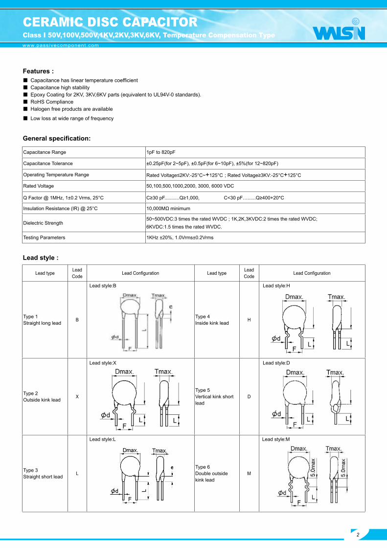
Features :
Lead typeLead Code
Lead Configuration Lead typeLead Code
Lead Configuration
Type 1Straight long lead B Type 4
Inside kink lead H
Type 2Outside kink lead X
Type 5Vertical kink shortlead
D
Type 3Straight short lead L
Type 6Double outsidekink lead
M
Lead style:B Lead style:H
Capacitance has linear temperature coefficient Capacitance high stability Epoxy Coating for 2KV, 3KV,6KV parts (equivalent to UL94V-0 standards). RoHS Compliance Halogen free products are available
Low loss at wide range of frequency
General specification:
Lead style :
Capacitance Range 1pF to 820pF
Capacitance Tolerance ±0.25pF(for 2~5pF), ±0.5pF(for 6~10pF), ±5%(for 12~820pF)
Operating Temperature Range Rated Voltage≤2KV:-25°C~+125°C ; Rated Voltage≥3KV:-25°C+125°C
Rated Voltage 50,100,500,1000,2000, 3000, 6000 VDC
Q Factor @ 1MHz, 1±0.2 Vrms, 25°C C≥30 pF...........Q≥1,000, C<30 pF…......Q≥400+20*C
Insulation Resistance (IR) @ 25°C 10,000MΩ minimum
Dielectric Strength50~500VDC:3 times the rated WVDC ; 1K,2K,3KVDC:2 times the rated WVDC;6KVDC:1.5 times the rated WVDC.
Testing Parameters 1KHz ±20%, 1.0Vrms±0.2Vrms
Lead style:X Lead style:D
Lead style:L Lead style:M
CERAMIC DISC CAPACITORClass I 50V,100V,500V,1KV,2KV,3KV,6KV, Temperature Compensation Type
2

www.passivecomponent.com
Manufacturing products rangeCap. Value VS. Rated voltage, Product diameter & Type
T.C. CH (Class I, Temperature:-25°C~+85°C, T.C.C.: 0±60ppm/°C)Rated voltage 50V(CH500)&100V(CH101) 500V(CH501) 1KV(CH102) 2KV(CH202)D Ø (Code) 040 050 060 070 080 100 110 120 050 060 070 100 050 060 070 080 100 060 080D max. (mm) 4.5 5.5 6.5 7.5 8.5 10.5 11.5 12.5 5.5 6.5 7.5 10.5 6.0 7.0 8.0 9.0 11.0 7.5 9.5T max. (mm) 3.5 3.5 3.5 3.5 3.5 3.5 3.5 3.5 4.0 4.0 4.0 4.0 4.5 4.5 4.5 4.5 4.5 4.5 4.5
0.5 0R51 010 0102 020 0203 030 0304 040 040 0405 050 050 0506 060 060 0607 070 070 0708 080 080 080 080
10 100 100 100 10012 120 120 120 12015 150 150 150 15018 180 180 180 18020 200 200 200 20022 220 220 220 22024 240 240 240 24027 270 270 270 27033 330 330 330 33036 360 360 360 36039 390 390 390 39047 470 470 470 47051 510 510 51056 560 560 56062 620 620 62068 680 680 68075 750 750 75082 820 820 820
100 101 101 101120 121 121150 151 151180 181200 201220 221240 241270 271300 301330 331360 361390 391
Packing T or B B T or B T or B T or BCoating Phenolic Resin Epoxy Resin
Marking
1. Temperaturecharacteristic
2. Nominal Capacitance
3. Capacitancetolerance 4. Rated voltage 5. Manufacturer’s
identification
CH : No marking, butrecognized by black color presented on the top of product.
Identified by 3-figurecode.5pF “5”100pF “101”
C:±0.25pFD:±0.5pF
J:±5%
50/100V Marked as underline Shall be marked as “ UK “ , but D Ø =6.0mm and less in Dia shall be omitted.
500V No marking (is blank)
1000V Marked “1KV”
2000V Marked “2KV”
Photo:
P .S .:Packing : T Packing in taping type . B Packing in bulk type .
CERAMIC DISC CAPACITORClass I 50V,100V,500V,1KV,2KV,3KV,6KV, Temperature Compensation
3

www.passivecomponent.com
Manufacturing product rangeCap. Value VS. Rated voltage, Product diameter & Type
T.C. SL (Class I, Temperature:+20°C~+85°C, T.C.C.: +350 ~ -1000ppm/°C)Rated voltage 50V(SL500);100V(SL101) 500V(SL501) 1KV(SL102) 2KV(SL202)D Ø (Code) 040 050 060 070 080 090 100 050 060 070 080 100 050 060 070 080 060 070 080 100 120D max. (mm) 4.5 5.5 6.5 7.5 8.5 9.5 10.5 5.5 6.5 7.5 9.0 10.5 6.0 7.0 8.0 9.0 7.5 8.5 9.5 11.5 13.5T max. (mm) 3.5 3.5 3.5 3.5 3.5 3.5 3.5 4.0 4.0 4.0 4.0 4.0 4.5 4.5 4.5 4.5 4.5 4.5 4.5 4.5 4.5
8 080 08010 100 100 10012 120 120 12015 150 150 150 15018 180 180 180 18020 200 200 200 20022 220 220 220 22024 240 240 240 24027 270 270 270 27030 300 300 300 30033 330 330 330 33036 350 360 360 36039 390 390 390 39047 470 470 470 47051 510 510 510 51056 560 560 560 56068 680 680 680 68075 750 750 750 75082 820 820 520 820
100 101 101 101 101120 121 121 121 121150 151 151 151 151180 181 181 181 181200 201 201 201 201220 221 221 221 221240 241 241 241270 271 271 271300 301 301 301330 331 331 331360 361 361390 391 391470 471500 501510 511560 561680 681750 751820 821
Packing T or B T or B T or B T or B Bcoating Phenolic Resin Epoxy Resin
Marking
1. Temperaturecharacteristic
2. Nominal Capacitance
3. Capacitancetolerance 4. Rated voltage 5. Manufacturer’s
identification
SL:No marking.
Identified by 3-figurecode.5pF “5”100pF “101”
C:±0.25pFD:±0.5pF
J:±5%
50/100V Marked as underlineShall be marked as “ UK “ , but D Ø =6.0mm and less in Dia shall be omitted.
500V No marking (is blank)
1000V Marked “1KV”
2000V Marked “2KV”
Photo:
CERAMIC DISC CAPACITORClass I 50V,100V,500V,1KV,2KV,3KV,6KV, Temperature Compensation Type
4

www.passivecomponent.com
Photo: CH SL
CERAMIC DISC CAPACITORClass I 50V,100V,500V,1KV,2KV,3KV,6KV, Temperature Compensation Type
5
Remark: K40- K100- K130- K300-
1. Temperature characteristic
2. Nominal capacitance
3. Capacitance tolerance 4. Rated voltage 5. Manufacturer's
identification6. Halogen and Pb free
CH:Be marked “CH”SL:No marking
1. Cap.≥100pF Ex.120pF →”121”2.Cap<100pFEx. 22pF→”22”
C: ±0.25pF D: ±0.5pF J: ±5%
3000V : Be marked “3KV”
Shall be marked as “ “, but when the body diameter ≤060 shall be omitted.
When the epoxy resin is Halogn and Pb free, there is a “_”marking.
Definition of date code marking :
7.Supplier of Epoxy 8.No. of test equipment
9.Factory of manufacture
10.Year of manufacture
11.Month of manufacture
12.Week of manufacture by month
Manufacturing product rangeCap. Value VS. Rated voltage, Product diameter & Type
T.C. CH (Class I, Temperature:-25°C~+85°C, T.C.C.:0±60ppm/°C) SL (Class I, Temperature:+20°C~+85°C, T.C.C.: +350 ~ -1000ppm/°C)Rated voltage 3KV(CH302) 3KV(SL302)
Ø (mm) 060 070 080 090 060 070 080D max. (mm) 7.5 8.5 9.5 10.5 7.5 8.5 9.5T max. (mm) 5.0 5.0 5.0 5.0 5.0 5.0 5.0
2 0203 0304 0405 050 0506 060 0607 070 0708 080 080
10 100 10012 120 12015 150 15018 180 18020 200 20022 220 22024 240 24027 270 27030 300 30033 330 33036 36039 39047 47051 51056 56062 62068 68075 75082 820
100 101120150180200220240270
ød (mm) 0.6 ± 0.06Packing BULKCoating Epoxy Resin

www.passivecomponent.com
1. Temperature characteristic
2. Nominal capacitance
3. Capacitance tolerance 4. Rated voltage 5. Manufacturer's
identification6. Halogen and Pb free
CH:Be marked “CH”SL:No marking
1. Cap.≥100pF Ex.120pF →”121”2.Cap<100pFEx. 22pF→”22”
C: ±0.25pF D: ±0.5pF J: ±5%
6000V : Be marked “6KV
Shall be marked as “ “, but when the body diameter ≤060 shall be omitted.
When the epoxy resin is Halogn and Pb free, there is a “_”marking.
Definition of date code marking :
7.Supplier of Epoxy 8.No. of test equipment
9.Factory of manufacture
10.Year of manufacture
11.Month of manufacture
12.Week of manufacture by month
Photo: CH SL
CERAMIC DISC CAPACITORClass I 50V,100V,500V,1KV,2KV,3KV,6KV, Temperature Compensation Type
6
Remark: K40- K100- K130- K300-
Manufacturing product rangeCap. Value VS. Rated voltage, Product diameter &Type
T.C. CH (Class I, Temperature:-25°C~+85°C, T.C.C.:0±60ppm/°C) SL (Class I, Temperature:-25°C~+85°C, T.C.C.: +350 ~ -1000ppm/°C)Rated voltage 6KV 6KV
Ø (mm) 060 080 090 110 060 080 090
D max. (mm) 7.5 9.5 10.5 12.5 7.5 9.5 10.5
T max. (mm) 5.0 5.0 5.0 5.0 5.0 5.0 5.0
2 020 020
3 030 030
5 050 050
6 060 060
7 070 070
8 080 080
10 100 100
12 120 120
15 150 150
18 180 180
20 200 200
22 220 220
27 270 270
30 300 300
33 330 330
39 390 390
47 470 470
51 510
56 560
6268 680
82 820
100 101
ød (mm) 0.6 +/-0.06

www.passivecomponent.com
Features :
Lead typeLead Code
Lead Configuration Lead typeLead Code
Lead Configuration
Type 1Straight long lead B Type 4
Inside kink lead H
Type 2Outside kink lead X
Type 5Vertical kink shortlead
D
Type 3Straight short lead L
Type 6Double outsidekink lead
M
Lead style:B Lead style:H
Capacitance has non-linear temperature coefficient. Large capacitance in small size. Epoxy Coating for 2KV and 3KV parts (equivalent to UL94V-0 standards). RoHS Compliance Halogen free products are available Wide range of general purposes applications.
General specification:
Lead style :
Capacitance Range 100pF to 22000pF
Capacitance Tolerance ±10%(for Y5P&X7R), ±20%(for Z5U), +80% -20%(for Z5V&Y5V)
Operating Temperature Range -25°C~ 85°C(Y5P,Y5V) ; 10°C~ 85°C(Z5U, Z5V) ; -55°C~ 125°C(X7R)
Rated Voltage 50,100,500,1000,2000,3000 VDC
Dissipation Factor (tan δ) Y5P, Z5U, X7R : tan δ ≤2.5% Z5V, Y5V : tan δ ≤5.0%
Insulation Resistance (IR) @ 25°C 10,000MΩ minimum or 200MΩ µF whichever is smaller
Dielectric Strength 50~500VDC: 2.5 times the rated WVDC; 1K,2K,3KVDC: 2 times the rated WVDC
Testing Parameters 1KHz ±20%, 1.0Vrms±0.2Vrms
Lead style:X Lead style:D
Lead style:L Lead style:M
CERAMIC DISC CAPACITORClass II 50V,100V,500V,1KV,2KV,3KV, Hi-K Type
7
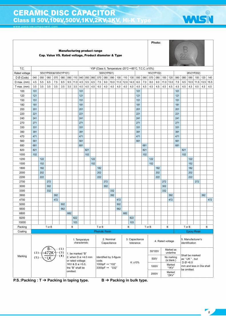
www.passivecomponent.com
Manufacturing product rangeCap. Value VS. Rated voltage, Product diameter & Type
T.C. Y5P (Class II, Temperature:-25°C~+85°C, T.C.C.:±10%)Rated voltage 50V(YP500)&100V(YP101) 500V(YP501) 1KV(YP102) 2KV(YP202)
D Ø (Code) 040 050 060 070 080 090 110 040 050 060 070 080 090 100 110 130 050 060 070 080 100 120 060 080 090 100 120 140
D max. (mm) 4.5 5.5 6.5 7.5 8.5 9.5 11.0 4.5 5.5 6.5 7.5 9.0 10.0 11.0 12.0 14.0 6.0 7.0 8.0 9.0 11.0 13.0 7.5 9.5 10.5 11.5 13.5 15.5
T max. (mm) 3.5 3.5 3.5 3.5 3.5 3.5 3.5 4.0 4.0 4.0 4.0 4.0 4.0 4.0 4.0 4.0 4.5 4.5 4.5 4.5 4.5 4.5 4.5 4.5 4.5 4.5 4.5 4.5
100 101 101 101 101
120 121 121 121 121
150 151 151 151 151
180 181 181 181 181
200 201 201 201 201
220 221 221 221 221
240 241 241 241 241
270 271 271 271 271
330 331 331 331 331
390 391 391 391 391
470 471 471 471 471
560 561 561 561 561
680 681 681 681 681
820 821 821 821 821
1000 102 102 102 102
1200 122 122 122 122
1500 152 152 152 152
1800 182 182 182 182
2000 202 202 202 202
2200 222 222 222 222
2700 272 272 272 272
3000 302 302 302
3300 332 332 332
3900 392 392 392 392
4700 472 472 472 472
5000 502 502
5600 562 562
6800 682 682
8200 822 822
10000 103 103
Packing T or B B T or B B T or B B T or B B
Coating Phenolic Resin Epoxy Resin
Marking
1. Temperaturecharacteristic
2. Nominal Capacitance
3. Capacitancetolerance 4. Rated voltage 5. Manufacturer’s
identification
1. be marked “B”2. when D ø =4.0 mmor rated voltage1KV & D ø =5.0,the “B” shall beomitted.
Identified by 3-figurecode.1000pF “102”3300pF “332”
K: ±10%
50/100V Marked asunderline
Shall be marked as “ UK “ , but D Ø =6.0mm and less in Dia shall be omitted.
500V No marking(is blank.)
1000V Marked“1KV”
2000V Marked“2KV”
Photo:
P .S .:Packing : T Packing in taping type . B Packing in bulk type .
CERAMIC DISC CAPACITORClass II 50V,100V,500V,1KV,2KV,3KV, Hi-K Type
8
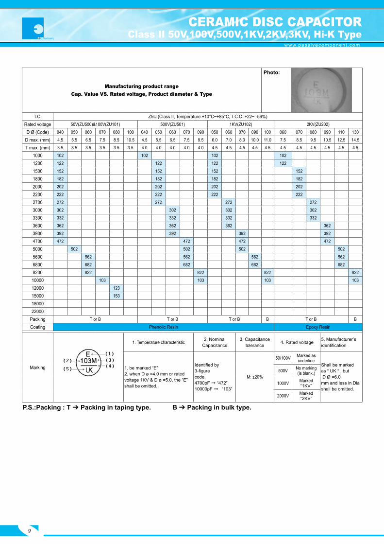
www.passivecomponent.com
Manufacturing product rangeCap. Value VS. Rated voltage, Product diameter & Type
T.C. Z5U (Class II, Temperature:+10°C~+85°C, T.C.C.:+22~ -56%)Rated voltage 50V(ZU500)&100V(ZU101) 500V(ZU501) 1KV(ZU102) 2KV(ZU202)
D Ø (Code) 040 050 060 070 080 100 040 050 060 070 090 050 060 070 090 100 060 070 080 090 110 130
D max. (mm) 4.5 5.5 6.5 7.5 8.5 10.5 4.5 5.5 6.5 7.5 9.5 6.0 7.0 8.0 10.0 11.0 7.5 8.5 9.5 10.5 12.5 14.5
T max. (mm) 3.5 3.5 3.5 3.5 3.5 3.5 4.0 4.0 4.0 4.0 4.0 4.5 4.5 4.5 4.5 4.5 4.5 4.5 4.5 4.5 4.5 4.5
1000 102 102 102 102
1200 122 122 122 122
1500 152 152 152 152
1800 182 182 182 182
2000 202 202 202 202
2200 222 222 222 222
2700 272 272 272 272
3000 302 302 302 302
3300 332 332 332 332
3600 362 362 362 362
3900 392 392 392 392
4700 472 472 472 472
5000 502 502 502 502
5600 562 562 562 562
6800 682 682 682 682
8200 822 822 822 822
10000 103 103 103 103
12000 123
15000 153
1800022000
Packing T or B T or B T or B B T or B B
Coating Phenolic Resin Epoxy Resin
Marking
1. Temperature characteristic 2. Nominal Capacitance
3. Capacitancetolerance 4. Rated voltage 5. Manufacturer’s
identification
1. be marked “E”2. when D ø =4.0 mm or ratedvoltage 1KV & D ø =5.0, the “E”shall be omitted.
Identified by 3-figurecode.4700pF “472”10000pF “103”
M: ±20%
50/100V Marked asunderline
Shall be marked as “ UK “ , but D Ø =6.0mm and less in Dia shall be omitted.
500V No marking(is blank.)
1000V Marked“1KV”
2000V Marked“2KV”
Photo:
P .S .:Packing : T Packing in taping type . B Packing in bulk type .
CERAMIC DISC CAPACITORClass II 50V,100V,500V,1KV,2KV,3KV, Hi-K Type
9

www.passivecomponent.com
Manufacturing product rangeCap. Value VS. Rated voltage, Product diameter & Type
T.C. Z5V (Class II, Temperature:+10°C~+85°C, T.C.C.:+22~ -82%)Rated voltage 50V(ZV500)&100V(ZV101) 500V(ZV501) 1KV(ZV102) 2KV(ZV202)
D Ø (Code) 050 060 070 080 080 060 080 100 120
D max. (mm) 5.5 6.5 7.5 8.5 9.0 7.0 9.0 11.0 13.5
T max. (mm) 3.5 3.5 3.5 3.5 4.0 4.5 4.5 4.5 4.5
1000 102
1200 122
1500 152 152
1800 182 182
2000 202 202
2200 222 222
2700 272 272
3000 302 302
3300 332
3600 362
3900 392 392
4700 472 472
5000 502
56006800820010000 103 103 103 103
150001800020000 203
22000 223
Packing T or B T or B T or B T or B T or B T or B T or B T or B B
Coating Phenolic Resin Epoxy Resin
Marking
1. Temperaturecharacteristic
2. Nominal Capacitance
3. Capacitancetolerance 4. Rated voltage 5. Manufacturer’s
identification
Z5V: the logo is“F”, but the “F”shall be omitted.
Identified by 3-figurecode.4700pF “472”10000pF “103”
Z: -20~+80%
50/100V Marked asunderline Shall be marked
as “ UK “ , but D Ø =6.0mm and less in Dia shall be omitted.
500V No marking(is blank.)
1000V Marked “1KV”
2000V Marked “2KV”
Photo:
P .S .:Packing : T Packing in taping type . B Packing in bulk type .
CERAMIC DISC CAPACITORClass II 50V,100V,500V,1KV,2KV,3KV, Hi-K Type
10

www.passivecomponent.com
Manufacturing product rangeCap. Value VS. Rated voltage, Product diameter & Type
T.C. X7R (Class II, Temperature:-55°C~+125°C, T.C.C.:±15%)
Ratedvoltage 50V 500V 1KV 2KV
D Ø(CODE) 040 050 060 070 080 100 040 050 060 070 080 090 100 110 120 140 050 060 070 080 100 110 060 070 080 100 120 130
D max. (mm) 4.5 5.5 6.5 7.5 8.5 10.5 4.5 5.5 6.5 7.5 8.5 9.5 10.5 11.5 12.5 14.5 6.0 7.0 8.0 9.0 11.0 12.0 7.5 8.5 9.5 11.5 13.5 14.5
T max. (mm) 3.5 3.5 3.5 3.5 3.5 3.5 4.0 4.0 4.0 4.0 4.0 4.0 4.0 4.0 4.0 4.0 4.5 4.5 4.5 4.5 4.5 4.5 4.5 4.5 4.5 4.5 4.5 4.5
100 101 101 101 101120 121 121 121 121150 151 151 151 151180 181 181 181 181200 201 201 201 201220 221 221 221 221240 241 241 241 241270 271 271 271 271300 301 301 301 301330 331 331 331 331360 361 361 361 361390 391 391 391 391470 471 471 471 471510 511 511 511 511560 561 561 561 561620 621 621 621 621680 681 681 681 681750 751 751 751820 821 821 821 821
1000 102 102 102 1021200 122 122 122 1221500 152 152 152 1521800 182 182 182 1822000 202 202 202 2022200 222 222 222 2222700 272 272 272 2723000 302 302 302 3023300 332 332 332 3323600 362 362 3623900 392 392 392 3924700 472 472 472 4725000 5025600 562 5626800 682 6828200 822 822
10000 103 103Packing T T B T B T BCoating Phenolic Resin Epoxy Resin
Marking
1. Temperaturecharacteristic
2. Nominal Capacitance
3. Capacitancetolerance 4. Rated voltage 5. Manufacturer’s
identification
be marked “R”
Identified by 3-figurecode.1000pF “102”3300pF “332”
K: ±10%
50/100V Marked asunderline Shall be marked
as “ UK “ , but D Ø =6.0mm and less in Diashall be omitted.
500V No marking(is blank.)
1000V Marked “1KV”
2000V Marked “2KV”
Photo:
P .S .:Packing : T Packing in taping type . B Packing in bulk type .
CERAMIC DISC CAPACITORClass II 50V,100V,500V,1KV,2KV,3KV, Hi-K Type
11

www.passivecomponent.com
1. Temperature characteristic
2. Nominal capacitance
3. Capacitance tolerance 4. Rated voltage 5. Manufacturer's
identification6. Halogen and Pb free
Y5P:Be marked“B”Z5U:Be marked“E”
Identified by 3-figure code when Cap.≥100pFEx.1000pF →”102”
K: ±10% (For Y5P)
M: ±20% (For Z5U)
3000V : Be marked “3kV”
Shall be marked as “ “, but when the body diameter ≤060 shall be omitted.
When the epoxy resin is Halogn and Pb free, there is a “_”marking.
Definition of date code marking :
7.Supplier of Epoxy 8.No. of test equipment
9.Factory of manufacture
10.Year of manufacture
11.Month of manufacture
12.Week of manufacture by month
Photo: Y5P Z5U
P.S.:Packing : T Packing in taping type. B Pack in bulk type.
CERAMIC DISC CAPACITORClass II 50V,100V,500V,1KV,2KV,3KV, Hi-K Type
12
Manufacturing product rangeCap. Value VS. Rated voltage, Product diameter & Type
T.C. Y5P (Class II, Temperature:-25°C~+85°C, T.C.C.:±10%) Z5U (Class II, Temperature:+10°C~+85°C, T.C.C.:+22~ -56%)Rated voltage 3KV (YP302) 3KV (ZU302)
D Ø 060 070 090 110 130 060 080 100 110 120 140 170D max. (mm) 8.0 9.0 11.0 13.0 15.0 8.0 10.0 12.0 13.0 14.0 16.0 19.0T max. (mm) 6.0 6.0 6.0 6.0 6.0 6.0 6.0 6.0 6.0 6.0 6.0 6.0
100 101120 121150 151180 181200 201220 221240 241270 271300 301330 331360 361390 391470 471510 511560 561620 621680 681750 751820 821
1000 102 1021200 122 1221500 152 1521800 182 1822000 202 2022200 222 2222700 2723300 3323600 3623900 3924700 4725000 5025600 5626800 6828200 822
10000 103Ø d (mm) 0.6 ± 0.06Packing BCoating Epoxy Resin

www.passivecomponent.com
Manufacturing product rangeCap. Value VS. Rated voltage, Product diameter & Type
T.C. Y5V (Class II, Temperature: -25°C~ +85°C, T.C.C.:+22% ~ -82%)
Rated voltage 50V 100V 500V 1KV 2KV
D Ø 040 050 060 080 040 050 060 050 070 080 100 070 120
D max. (mm) 4.5 5.5 6.6 8.5 4.5 5.5 6.6 5.5 7.5 8.5 11.0 8.5 13.5
T max. (mm) 3.5 3.5 3.5 3.5 3.5 3.5 3.5 4.0 4.0 4.0 4.5 5.0 5.0
1000 102 102 102
2200 222 222 222 222
4700 472 472 472
10000 103 103 103 103 103
22000 223
47000
Packing T or B T or B T or B T or B B
Coating PHENOL EPOXY
Marking
1. TemperatureCharacteristic
2. Nominal Capacitance
3. Capacitancetolerance 4. Rated voltage 5. Manufacturer’s
identification
Y5V: the productlogo is “F”, but it isomitted on marking.
Identified by 3-figurecode.4700pF “472”10000 pF “103”
Z: -20 ~ +80%
50V/100V Marked as underline
Shall be marked as “ UK “ , but D Ø =6.0mm and less in Diashall be omitted.
500V No marking (is blank.)
1000V Marked “1KV”
2000V Marked “2KV”
P .S .:Packing : T Packing in taping type . B Packing in bulk type .
CERAMIC DISC CAPACITORClass II 50V,100V,500V,1KV,2KV,3KV, Hi-K Type
13

www.passivecomponent.com
Specification :Manufacturing Product Range
T.C. FY (Y5V) Class III
Rated voltage 16V 25V 50V
D Ø 050 060 050 060 050 060
D max. (mm) 6.0 7.0 6.0 7.0 6.0 7.0
T max. (mm) 3.5 3.5 3.5 3.5 3.5 3.5
22000 223 223 223
33000 333 333 333
47000 473 473 473
68000 683 683 683
100000 104 104 104
Features : Large capacitance in small size. Low loss at wide range of frequency. Cost saving by replacing film capacitors. Capacitance has linear temperature coefficient. Stable capacitance change over specified temperature range. RoHS Compliance Halogen free products are available
General specification:
Capacitance Range 22000pF to 100000pF
Capacitance Tolerance ±20%, +80%-20%
Operating Temperature Range -25°C ~ 85°C
Rated Voltage 16,25&50 VDC
Dissipation Factor (tan δ) 16V........ tan δ ≤7.5% 25/50V........ tan δ ≤5.0%
Insulation Resistance (IR) @ 25°C 16V........100MΩ Minimum or 10MΩ µF 25/50V........1000MΩ Minimum or 20MΩ µF
Dielectric Strength 2 times the rated WVDC
Testing Parameters 1KHz ±20%, 0.1Vrms Maximum
Marking
1. TemperatureCharacteristic
2. Nominal Capacitance
3. Capacitance tolerance 4. Rated voltage 5. Manufacturer’s
identification
Y5V: the productlogo is “F”, but it isomitted on marking.
Identified by 3-figurecode.4700pF “472”10000 pF “103”
M: ±20%Z: -20~+80%
16V&25V Marked With code:16V“16V“ 25V“25V“
Shall be marked as “UK “ , but D Ø =6.0mm and less in Diashall be omitted.50V Shall be Marked“_” under
the rated copacitance.
CERAMIC DISC CAPACITORClass III Semi-Conductive Type
14
DR
ØdL
www.passivecomponent.com
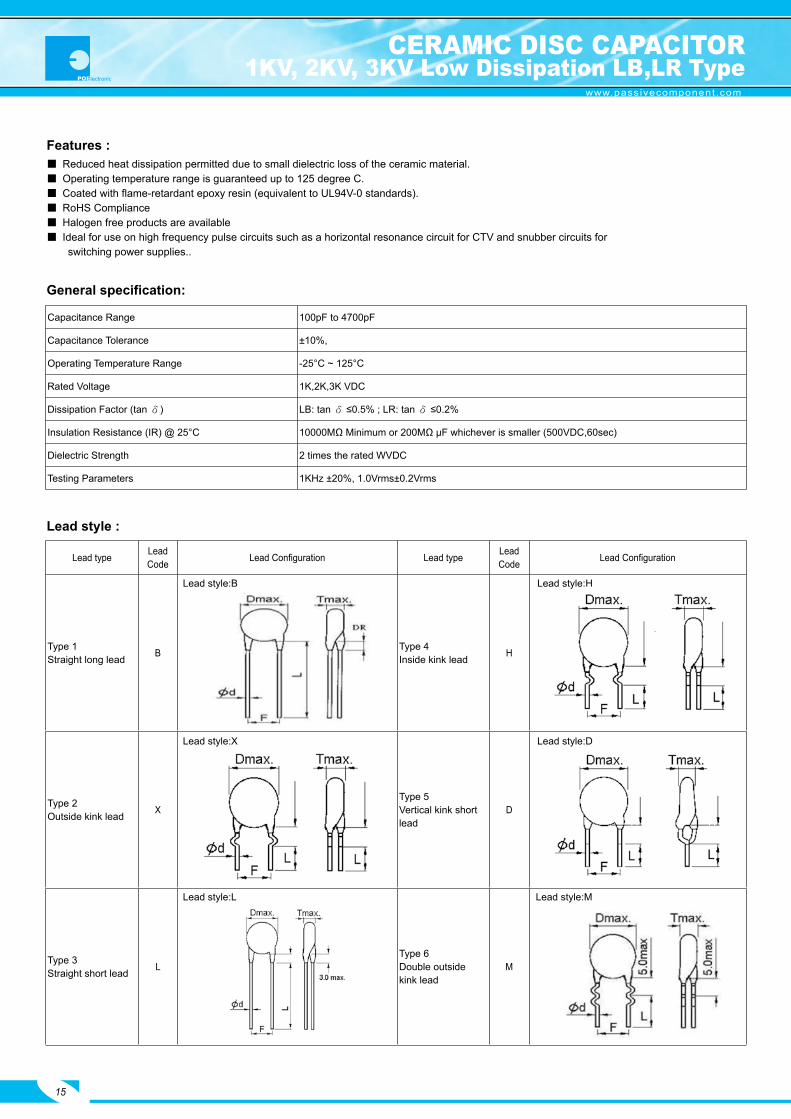
Features :
Lead typeLead Code
Lead Configuration Lead typeLead Code
Lead Configuration
Type 1Straight long lead B Type 4
Inside kink lead H
Type 2Outside kink lead X
Type 5Vertical kink shortlead
D
Type 3Straight short lead L
Type 6Double outsidekink lead
M
Lead style:B Lead style:H
Reduced heat dissipation permitted due to small dielectric loss of the ceramic material. Operating temperature range is guaranteed up to 125 degree C. Coated with flame-retardant epoxy resin (equivalent to UL94V-0 standards). RoHS Compliance Halogen free products are available Ideal for use on high frequency pulse circuits such as a horizontal resonance circuit for CTV and snubber circuits for switching power supplies..
General specification:
Lead style :
Capacitance Range 100pF to 4700pF
Capacitance Tolerance ±10%,
Operating Temperature Range -25°C ~ 125°C
Rated Voltage 1K,2K,3K VDC
Dissipation Factor (tan δ) LB: tan δ ≤0.5% ; LR: tan δ ≤0.2%
Insulation Resistance (IR) @ 25°C 10000MΩ Minimum or 200MΩ µF whichever is smaller (500VDC,60sec)
Dielectric Strength 2 times the rated WVDC
Testing Parameters 1KHz ±20%, 1.0Vrms±0.2Vrms
Lead style:X Lead style:D
Lead style:L Lead style:M
CERAMIC DISC CAPACITOR1KV, 2KV, 3KV Low Dissipation LB,LR Type
15

www.passivecomponent.com
Part Number Rated Voltage Cap. in pF Cap. Tol. (%)Dimensions in mm
D Max. T Max. LB 102101K050 1000VDC 100 ±10% 6.5 4.5LB 102151K050 1000VDC 150 ±10% 6.5 4.5LB 102181K050 1000VDC 180 ±10% 6.5 4.5LB 102221K050 1000VDC 220 ±10% 6.5 4.5LB 102271K050 1000VDC 270 ±10% 6.5 4.5LB 102331K050 1000VDC 330 ±10% 6.5 4.5LB 102391K050 1000VDC 390 ±10% 6.5 4.5LB 102471K050 1000VDC 470 ±10% 6.5 4.5LB 102561K050 1000VDC 560 ±10% 6.5 4.5LB 102681K060 1000VDC 680 ±10% 7.5 4.5LB 102821K060 1000VDC 820 ±10% 7.5 4.5LB 102102K060 1000VDC 1000 ±10% 7.5 4.5LB 102152K070 1000VDC 1500 ±10% 8.5 4.5LB 102182K070 1000VDC 1800 ±10% 8.5 4.5LB 102222K080 1000VDC 2200 ±10% 9.5 4.5LB 102332K100 1000VDC 3300 ±10% 11.5 4.5LB 102392K100 1000VDC 3900 ±10% 11.5 4.5LB 102472K120 1000VDC 4700 ±10% 13.5 4.5LB 202101K050 2000VDC 100 ±10% 6.5 5.0LB 202151K050 2000VDC 150 ±10% 6.5 5.0LB 202221K050 2000VDC 220 ±10% 6.5 5.0LB 202271K050 2000VDC 270 ±10% 6.5 5.0LB 202331K050 2000VDC 330 ±10% 6.5 5.0LB 202391K050 2000VDC 390 ±10% 6.5 5.0LB 202471K050 2000VDC 470 ±10% 7.5 5.0LB 202561K060 2000VDC 560 ±10% 7.5 5.0LB 202681K060 2000VDC 680 ±10% 8.5 5.0LB 202821K070 2000VDC 820 ±10% 8.5 5.0LB 202102K070 2000VDC 1000 ±10% 8.5 5.0LB 202122K070 2000VDC 1200 ±10% 8.5 5.0LB 202152K080 2000VDC 1500 ±10% 9.5 5.0LB 202182K090 2000VDC 1800 ±10% 10.5 5.0LB 202222K100 2000VDC 2200 ±10% 11.5 5.0LB 202272K110 2000VDC 2700 ±10% 12.5 5.0LB 202332K120 2000VDC 3300 ±10% 13.5 5.0LB 202392K130 2000VDC 3900 ±10% 14.5 5.0LB 202472K140 2000VDC 4700 ±10% 15.5 5.0LB 302101K050 3000VDC 100 ±10% 6.5 6.0LB 302151K050 3000VDC 150 ±10% 6.5 6.0LB 302222K050 3000VDC 220 ±10% 6.5 6.0LB 302331K050 3000VDC 330 ±10% 6.5 6.0LB 302391K050 3000VDC 390 ±10% 6.5 6.0LB 302471K060 3000VDC 470 ±10% 7.5 6.0LB 302561K060 3000VDC 560 ±10% 7.5 6.0LB 302681K070 3000VDC 680 ±10% 8.5 6.0LB 302821K080 3000VDC 820 ±10% 9.5 6.0LB 302102K080 3000VDC 1000 ±10% 9.5 6.0LB 302152K100 3000VDC 1500 ±10% 11.5 6.0LB 302222K120 3000VDC 2200 ±10% 13.5 6.0LB 302272K130 3000VDC 2700 ±10% 14.5 6.0LB 302332K140 3000VDC 3300 ±10% 15.5 6.0LB 302392K150 3000VDC 3900 ±10% 16.5 6.0LB 302472K160 3000VDC 4700 ±10% 17.5 6.0
LB Series
CERAMIC DISC CAPACITOR1KV, 2KV, 3KV Low Dissipation LB,LR Type
16

www.passivecomponent.com
Part Number Rated Voltage Cap. in pF Cap. Tol. (%)Dimensions in mm
D Max. T Max. LR 102101K050 1000VDC 100 ±10% 6.5 4.5LR 102151K050 1000VDC 150 ±10% 6.5 4.5LR 102221K050 1000VDC 220 ±10% 6.5 4.5LR 102271K050 1000VDC 270 ±10% 6.5 4.5LR 102331K050 1000VDC 330 ±10% 6.5 4.5LR 102391K050 1000VDC 390 ±10% 6.5 4.5LR 102471K050 1000VDC 470 ±10% 6.5 4.5LR 102681K060 1000VDC 680 ±10% 7.5 4.5LR 102102K070 1000VDC 1000 ±10% 8.5 4.5LR 102152K090 1000VDC 1500 ±10% 10.5 4.5LR 102222K100 1000VDC 2200 ±10% 11.5 4.5LR 102332K130 1000VDC 3300 ±10% 14.5 4.5LR 202101K050 2000VDC 100 ±10% 6.5 5.0LR 202151K050 2000VDC 150 ±10% 6.5 5.0LR 202221K050 2000VDC 220 ±10% 6.5 5.0LR 202271K050 2000VDC 270 ±10% 6.5 5.0LR 202331K060 2000VDC 330 ±10% 7.5 5.0LR 202391K060 2000VDC 390 ±10% 7.5 5.0LR 202471K060 2000VDC 470 ±10% 7.5 5.0LR 202561K070 2000VDC 560 ±10% 8.5 5.0LR 202681K070 2000VDC 680 ±10% 8.5 5.0LR 202821K080 2000VDC 820 ±10% 9.5 5.0LR 202102K090 2000VDC 1000 ±10% 10.5 5.0LR 202122K100 2000VDC 1200 ±10% 11.5 5.0LR 202152K110 2000VDC 1500 ±10% 12.5 5.0LR 202182K120 2000VDC 1800 ±10% 13.5 5.0LR 202222K130 2000VDC 2200 ±10% 14.5 5.0LR 202332K160 2000VDC 3300 ±10% 17.5 5.0LR 302101K050 3000VDC 100 ±10% 6.5 6.0LR 302151K050 3000VDC 150 ±10% 6.5 6.0LR 302221K050 3000VDC 220 ±10% 6.5 6.0LR 302331K060 3000VDC 330 ±10% 7.5 6.0LR 302391K070 3000VDC 390 ±10% 8.5 6.0LR 302471K080 3000VDC 470 ±10% 9.5 6.0LR 302561K080 3000VDC 560 ±10% 9.5 6.0LR 302681K090 3000VDC 680 ±10% 10.5 6.0LR 302821K100 3000VDC 820 ±10% 11.5 6.0LR 302102K100 3000VDC 1000 ±10% 11.5 6.0LR 302152K130 3000VDC 1500 ±10% 14.5 6.0LR 302222K150 3000VDC 2200 ±10% 16.5 6.0
LR series:
CERAMIC DISC CAPACITOR1KV, 2KV, 3KV Low Dissipation LB,LR Type
17

www.passivecomponent.com
LR LB
(1) Temp. Char. And D.F.Cap.change:-30%~+15%(-25°Cto+125°C)D.F:0.2% Max
Cap. change: ±10%(-25°C~85°C)D.F:0.5% Max
(2) Nominal CapacitanceIdentified By 3-Figure Code.Ex. 100pf “101”°A1000 Pf “102”
(3) Rated Voltage
1000V Marked with code “1KV” In case of DC 1000V
2000V Marked with code “2KV” In case of DC 2000V
3000V Marked with code “3KV” In case of DC 3000V
(4) Capacitance Tolerance K=±10%
(5) Manufacturer’s Identification Shall Be Marked As “ UK “ , But DΦ=6.0 Mm And Less In Dia Shall Be Omitted.
(6) Halogen and Pb free When the epoxy resin is Halogen and Pb free,there is a “_”marking.
Marking:
Temp. Char.
Marking
Item
CERAMIC DISC CAPACITOR1KV, 2KV, 3KV Low Dissipation LB,LR Type
18
L R (1)(4)
(6)(5)
(3)
(2)
UK
471K1KV
LB (1)
(4)
(5)(6)(3)
(2)
UK
102K2KV

www.passivecomponent.com
Caution 1 .Caution (Rating)
1-1 Operating Voltage When dc-rated capacitors are to be used in ac or ripple current circuits, be sure to maintain the Vp-p value of the applied voltage or the Vo-p which contains dc bias within the rated voltage range. When the voltage is applied to the circuit, starting or stopping may generate irregular voltage for a transit period because of resonance or switching. Be sure to use a capacitor with a rated voltage range that includes these irregular voltages. When using the low-dissipation (LB, LR Char.) series in a high-frequency and high-voltage circuit, be sure to read the instructions in item 4.
1-2 Operating Temperature And Self-Generated Heat Keep the surface temperature of a capacitor below the upper limit of its rated operating temperature range. be sure to take into account the heat generated by the capacitor itself. When the capacitor is used in a high-frequency current, pulse current or similar current, it may self-generate heat due to dielectric loss. The frequency of the applied sine wave voltage should be less than 300kHz. the applied voltage load (*) should be such that the capacitor’s self-generated heat is within 20°c at an atmosphere temperature of 25°c. When measuring, use a thermocouple of small thermal capacity-k of ø0.1mm in conditions where the capacitor is not affected by radiant heat from other components or surrounding ambient fluctuations. Excessive heat may lead to deterioration of the capacitor’s characteristics and reliability. (Never attempt to perform measurement with the cooling fan running. otherwise, accurate measurement cannot be ensured.)
1-3 Fail-Safe When capacitor is broken, failure may result in a short circuit. Be sure to provide an appropriate fail-safe function like a fuse on your product if failure would follow an electric shock, fire or fume.
1-4 Load Reduction and Self-generated Heat During Application of High-frequency and High-voltage Due to the low self-heating characteristics of low dissipation capacitors, the allowable electric power of these capacitors is generally much higher than that of B characteristic capacitors. However, in case the self heating temperature is 20°C under a high-frequency voltage whose peak-to-peak value equals the capacitor’s rated voltage, the capacitor’s power consumption may exceed it’s allowable electric power. Therefore, when using the Low D.F. series in a high-frequency and high-voltage circuit with a frequency of 1kHz or higher, make sure that the Vp-p values including the DC bias, do not exceed the applied voltage value specified in Table 1. Also make sure that the self-heating temperature (the difference between the capacitor’s surface temperature and the capacitor’s ambient temperature) at an ambient temperature of 25°C does not exceed the value specified in Table 1. As shown in Fig. 2, the self-heating temperature depends on the ambient temperature. Therefore, if you are not able to set the ambient temperature to approximately 25°C, please contact our sales representatives or product engineers.
Voltage DC Voltage DC + AC Voltage AC Voltage Pulse Voltage (1) Pulse Voltage (2)
Positional
measurement
CERAMIC DISC CAPACITOR1KV, 2KV, 3KV Low Dissipation LB,LR Type
19

www.passivecomponent.com
[Table 1] Allowable conditions at high frequency
Series DC rated voltageAllowable conditions at High-frequency *3
Capacitor’s ambient temp. *2Bulk Code Self-heating temp.(25°C ambient temp.) *1
LB 、 LR
1KV800Vp-p 20°C Max
-25 ~ +125°C
1000Vp-p 5 °C Max
2KV1400Vp-p 20°C Max
2000Vp-p 5 °C Max
3KV1600Vp-p 20°C Max
3000Vp-p 5 °C Max
*1 Fig. 1 shows the relationship between the applied voltage and the allowable self-heating temperature regarding 1 to 2KV rated voltage of the low D.F. series LB,LR characteristic.*2 Fig. 2 When the ambient temperature is 85 to 125°C, the applied voltage needs to be further reduced. If the low D.F. series needs o be used at an ambient temperature of 85 to 125°C, please contact our sales representatives or product engineers.*3 Fig. 3 shows reference data on the allowable voltage-frequency characteristic for a sine wave voltage.
Failure to follow the above cautions (items 1-1to 1-4) may result, worst case, in a short circuitand cause fuming or partial dispersion when the product is used .
Fig 1:Relationship Between Applied Voltage and Self-heating Temperature(Allowable Self-heating Temp . at 25°C Ambient Temp .)
CERAMIC DISC CAPACITOR1KV, 2KV, 3KV Low Dissipation LB,LR Type
20

www.passivecomponent.com
Fig 2:Dependence of Self-heating Temperature on Ambient Temperature .
Fig 3:Allowable Voltage ( Sine Wave Voltage ) – Frequency Characteristics (At AmbientTemperature of 85°C or less)
CERAMIC DISC CAPACITOR1KV, 2KV, 3KV Low Dissipation LB,LR Type
21
www.passivecomponent.com
Because of influence of harmonics, when the applied voltage is a rectangular wave or pulsewave voltage (instead of a sine wave voltage), the heat generated by the capacitor is higherthan the value obtained by application of the sine wave with the same fundamental frequency.Roughly calculated for reference, the allowable voltage for a rectangular wave or pulse wavecorresponds approximately to the allowable voltage for a sine wave whose fundamentalfrequency is twice as large as that of the rectangular wave or pulse wave. This allowablevoltage, however, varies depending on the voltage and current waveforms.Therefore, you are requested to make sure that the self-heating temperature is not higher thanthe value specified in Table 1.
2 .Caution (Storage And Operating Condition) I. Operating And Storage Environment The insulating coating of capacitors does not form a perfect seal; therefore, do not use or store capacitors in a corrosive atmosphere, especially where chloride gas, sulfide gas, acid, alkali, salt or the like are present. And avoid exposure to Moisture. Before cleaning, bonding or molding this product, verify that these processes do not affect product quality by testing the performance of a cleaned, bonded or molded product in the intended equipment. Store the capacitors where the temperature and relative humidity do not exceed –10 to 40 degrees centigrade and 15 to 85 %. Use capacitors within 6 months. Failure to follow the above cautions may result, worst case, in a short circuit and cause fuming or partial dispersion when the product is used.
3 .Caution (Soldering And Mounting) I. Vibration And Impact Do not expose a capacitor or its leads to excessive shock or vibration during use. II. Soldering When soldering this product to a PCB / PWB, do not exceed the solder heat resistance specification of the capacitor. Subjecting this product to excessive heating could melt the internal junction solder and may result in thermal shocks that can crack the ceramic element. When soldering capacitor with a soldering iron, it should be performed in following conditions. Temperature of iron-tip: 400°C Max. Soldering iron wattage: 50W Max. Soldering time: 3.5 sec. Max.Failure to follow the above cautions may result, worst case, in a short circuit and causefuming or partial dispersion when the product is used.
4 . Caution (Handling) Vibration And Impact Do not expose a capacitor or its leads to excessive shock or vibration during use. Failure to follow the above cautions may result, worst case, in a short circuit and cause fuming or partial dispersion when the product is used.
Notice1 .Notice (Soldering And Mounting) Cleaning (ultrasonic cleaning) To perform ultrasonic cleaning, observe the following conditions. Rinse bath capacity: output of 20-watts per liter or less. Rinsing time: 5 min. Maximum. Do not vibrate the Pcb/Pwb directly. Excessive ultrasonic cleaning may lead to fatigue destruction of the lead wires.2 .Notice (Rating) Low D.F. series Capacitance might change greatly depending on the surrounding temperature or an applied voltage. So, it is not likely to be suitable for use in a time constant circuit. Please contact us if you need detailed information.
CERAMIC DISC CAPACITOR1KV, 2KV, 3KV Low Dissipation LB,LR Type
22

www.passivecomponent.com
➋ Type (identified by 3-figure code): 0AC=AC Type(X1/Y2) ; 0AH=AH Type(X1:400V~/Y1:250V); 1AH=AH Type(X1:400V~/Y1:400V)➌ Capacitance (identified by 3-figure code)➍ Capacitance tolerance (identified by code)➎ Nominal body diameter dimension (identified by 3-figure code)➏ Kinked Lead style
➐ Packing mode and lead length (identified by 2-figure code)
To order, please also specify Pan Overseas Part No . as the following example for SAP system :
YV 0AC 472 M 100 L 25 C 7 B
➊ ➋ ➌ ➍ ➎ ➏ ➐ ➑ ➒ ➓
➊ Temperature characteristic (identified code):
Taping Code Description Bulk Code Description (ex)
AM Box and Pitch : 25.4 mm (Pitch=10.0mm) 3E lead length L:3.5mm
AF Box and Pitch : 15.0 mm (Pitch=7.5mm) 04 lead length L:4.0mm
AT Box and Pitch : 30.0 mm (Pitch=7.5mm or 10.0mm) 4E lead length L:4.5mm
20 lead length L:20mm
Code CH(NPO) SL YP(Y5P) YU(Y5U) YV(Y5V)
Cap. Change (%) 0±60PPM/°C -1000~+350PPM/°C ±10% +20% to -55% +30% to -80%
Lead type& Code
Lead ConfigurationLead type& Code
Lead ConfigurationLead type& Code
Lead Configuration
Type Bstraightlong lead
Type XOutsidekinklead
Type LStraightshort lead
Type DVerticalkink shortlead
Type HInsidekinklead
Lead style:B Lead style:X Lead style:L
Lead style:D Lead style:H
Code Description
A ±0.5 mm (only for kink lead type)
B ±1.0mm
C MIN.
D Taping special purpose
Code Description
7 7.5 ± 1mm (AC Type)
0 10 ± 1mm (AH Type & AC Type)
Code Description
B Epoxy Resin Pb free
H Halogen and Pb free, epoxy resin
➑ Length tolerance ➒ Pitch
➓ Epoxy resin code
SAFETY.STANDARD CERAMIC CAPACITORSAP Part Number Explanation
23

www.passivecomponent.com
Introduction:
These Safety Recognized Ceramic Capacitors are specifically designed for AC applications andmeet the safety requirements of various safety standard agencies. They are ideal for across theline and line by-pass applications.
Features: Compact size Cost effective products Ideal for across the line applications Safety Standard Recognized for AC applications Coated with flame-retardant epoxy resin (equivalent to UL94V-0 standards). RoHS Compliance Halogen free products are available
Capacitance Range AH:2pF to 4700pF; AC:2pF to 10000pF
Capacitance Tolerance ±0.25pF, ±0. 5pF, ±5%, ±10%, ±20%
Operating Temperature Range -25°C ~ 125°C
Temperature Coefficient ( C Max)0±60PPM/°C(CH), -1000~+350PPM/°C(SL), ±10% (Y5P), +30-80% (Y5V),+20-55% (Y5U)
Rated Voltage AH Type : X1: 400Vac./ Y1 : 400Vac. or 250Vac;AC Type : X1 : 400Vac. / Y2 : 250Vac.
Dissipation Factor(tanδ) or Q
CH&SL: 30pF&above: ≥1000 Below 30PF: ≥400+20xC @20°C , 1MHZ, 1±0.2VrmsY5P:2.5% Max. @20°C , 1KHZ, 1±0.2VrmsY5U: 2.5% Max. @20°C , 1KHZ, 1±0.2VrmsY5V: 5.0% Max. @20°C , 1KHZ, 1±0.2Vrms
Insulation Resistance 10000MΩ at 500VDC for 60 Seconds
Dielectric StrengthAC Type:1500VAC for 60 Seconds (Lead space=5mm)
AC Type:2600VAC for 60 Seconds (Lead space=7.5 & 10 mm)
AH Type:4000VAC for 60 Seconds(Lead space=10mm)
Agencies UL CASVDE, SEMKO, NEMKO, DEMKO,
FIMKO, SEV, KEMA CQC KTL
Standard NO. UL 1414 C22.2NO.1-04 IEC60384-141ed3 (2005) GB/T 14472-1998 K60384-14
Rated VoltageAH:250VACAC:250VAC
AH:250VACAC:250VAC
AH: X1 400VAC / Y1 250VAC,400VAC AC: X1 400VAC / Y2 250VAC
AH: X1 400VAC / Y1 400VAC AC: X1 400VAC / Y2 250VAC
AH: X1 400VAC / Y1 400VAC AC: X1 400VAC / Y2 250VAC
Capacitance
Value (pF)AH:2~4700
AC:2~10000AH:2~4700
AC:2~10000AH:2~4700
AC:2~10000AH:2~4700
AC:2~10000AH:2~4700
AC:2~10000
Approval standards:
General specification:
SAFETY STANDARD CERAMIC CAPACITORAH Type-Class X1/Y1 AC Type-Class X1/Y2
24

www.passivecomponent.com
Typical Characteristic Curves:
SAFETY.STANDARD CERAMIC CAPACITORAH Type-Class X1/Y1 AC Type-Class X1/Y2
25

www.passivecomponent.com
AH Type-Class X1/Y1
Part Number Temp. Char. Cap.(pF) Tol.Dimension (mm)
D max. T max. F Wire Dia.YP0AH101K060
Y5P
100
±10%
7.0
5.0 10±1 0.60+0.1-0.05
YP0AH151K060 150 7.0YP0AH221K060 220 7.0YP0AH331K060 330 7.0YP0AH471K070 470 8.0YP0AH561K100 560 11.0YP0AH681K080 680 9.0YP0AH102K100 1000 11.0YU0AH102M070
Y5U
1000
±20%
8.0
5.0 10±1 0.60+0.1-0.05
YU0AH152M080 1500 9.0YU0AH222M090 2200 10.0YU0AH332M110 3300 12.0YU0AH392M120 3900 14.0YU0AH472M130 4700 14.0YV0AH102M060
Y5V
1000
±20%
7.0
5.5 10±1 0.60+0.1-0.05YV0AH152M070 1500 8.0YV0AH222M080 2200 9.0YV0AH332M100 3300 11.0YV0AH472M110 4700 12.0CH0AH***C060
CH(NPO)
2,3,4,5 ±0.25pF 7.0
5.0 10±1 0.60+0.1-0.05CH0AH***D060 6,7,8,9,10 ±0.5pF 7.0CH0AH***J060 12 ±5%
±5%7.0
CH0AH***J070 15,18,20,22,24,27 8.0
SL0AH***J060
SL
15,18,20,2224,27,3033,36,39
±5%
7.0
5.0 10±1 0.60+0.1-0.05SL0AH***J070 47,50,51,56,65 8.0SL0AH820J080 68,75,82 9.0SL0AH101J090 100 10.0
SAFETY STANDARD CERAMIC CAPACITORDetail Specification
26

www.passivecomponent.com
AC Type-Class X1/Y2
= Lead Code : Please consult our part number explanation on page 23 for detail lead space, lead length, and lead configuration.
Part Number Temp. Char. Cap.(pF) Tol.Dimension (mm)
D max. T max. F Wire Dia.YP0AC101K060
Y5P
100
±10%
7.0
5.07.5±110±1
0.60+0.1-0.05
YP0AC151K080 150 9.0YP0AC221K080 220 9.0YP0AC331K080 330 9.0YP0AC471K060 470 7.0YP0AC561K080 560 9.0YP0AC681K090 680 10.0YP0AC821K100 820 11.0YP0AC102K080 1000 9.0YU0AC102M060
Y5U
1000
±20%
7.0
5.07.5±110±1
0.60+0.1-0.05
YU0AC152M100 1500 11.0YU0AC222M080 2200 9.0YU0AC332M100 3300 11.0YU0AC392M120 3900 13.0YU0AC472M120 4700 13.0YV0AC102M060
Y5V
1000
±20%
7.0
5.07.5±1
0.60+0.1-0.05
YV0AC152M060 1500 7.0YV0AC222M060 2200 7.0YV0AC332M080 3300 9.0YV0AC392M110 3900 12.0YV0AC472M100 4700 11.0YV0AC682M120 6800 13.0YV0AC103M140 10000 15.0 10±1CH0AC***C060
CH(NPO)
2,3,4,5 ±0.25pF 7.0
5.07.5±110±1
0.60+0.1-0.05
CH0AC***D060 6,7,8,9,10 ±0.5pF 7.0CH0AC***J060 12,15
±5%
7.0CH0AC***J070 18,20,22,24 8.0CH0AC***J080 27,30,33 9.0CH0AC390J090 36,39 10.0CH0AC470J100 47 11.0
SL0AC***J060
SL
10,12,15,18,2022,24,27,30,3336,39,47,50,51
±5%
7.0
5.07.5±110±1
0.60+0.1-0.05SL0AC***J070 52,62,68,75 8.0SL0AC820J080 82 9.0SL0AC101J090 100 10.0
SAFETY STANDARD CERAMIC CAPACITORDetail Specification
27
www.passivecomponent.com
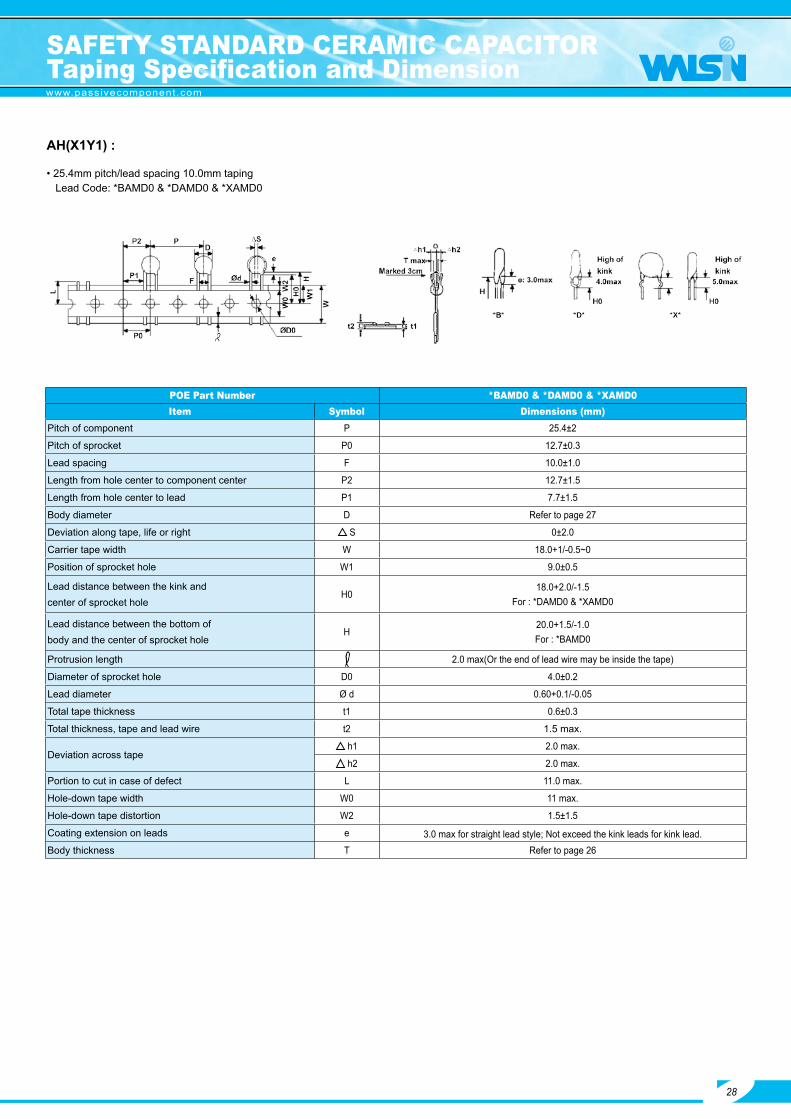
AH(X1Y1) :
• 25.4mm pitch/lead spacing 10.0mm taping Lead Code: *BAMD0 & *DAMD0 & *XAMD0
POE Part Number *BAMD0 & *DAMD0 & *XAMD0Item Symbol Dimensions (mm)
Pitch of component P 25.4±2
Pitch of sprocket P0 12.7±0.3
Lead spacing F 10.0±1.0
Length from hole center to component center P2 12.7±1.5
Length from hole center to lead P1 7.7±1.5
Body diameter D Refer to page 27
Deviation along tape, life or right S 0±2.0
Carrier tape width W 18.0+1/-0.5~0
Position of sprocket hole W1 9.0±0.5
Lead distance between the kink andcenter of sprocket hole
H018.0+2.0/-1.5
For : *DAMD0 & *XAMD0
Lead distance between the bottom ofbody and the center of sprocket hole
H20.0+1.5/-1.0For : *BAMD0
Protrusion length 2.0 max(Or the end of lead wire may be inside the tape)
Diameter of sprocket hole D0 4.0±0.2
Lead diameter Ø d 0.60+0.1/-0.05
Total tape thickness t1 0.6±0.3
Total thickness, tape and lead wire t2 1.5 max.
Deviation across tape h1 2.0 max.
h2 2.0 max.
Portion to cut in case of defect L 11.0 max.
Hole-down tape width W0 11 max.
Hole-down tape distortion W2 1.5±1.5
Coating extension on leads e 3.0 max for straight lead style; Not exceed the kink leads for kink lead.Body thickness T Refer to page 26
SAFETY STANDARD CERAMIC CAPACITORTaping Specification and Dimension
28

www.passivecomponent.com
1. Nominal Capacitance AH
2. Nominal Capacitance 3-digit-system
3. Capacitance Tolerance C:±0.25pF,D:±0.5pF,J:±5%,K:±10%,M:±20%
4. Company Name Code UK5. Manufactured Date Abbreviation ex.:
6. Approved Monogram:
(1) VDE approval mark IEC 60384-14 3rd(2005). Class Code: X1:400V~, Y1:250V~or400V~
(2) UL approval mark
(3) CSA approval mark (4) SEMKO approval mark
(5) NEMKO approval mark (6) DEMKO approval mark
(7) FIMKO approval mark (8) SEV approval mark
(9) CQC approval mark
Ex: One side: Two sides:
29
SAFETY STANDARD CERAMIC CAPACITORTaping Specification and Dimension
Marking :
*Marking by the stamp or laser.
*The marking can be printed on either one side or two side of coating body.
*C 71,Marked with code “_”stand for Halogen and Pb free ; No marked with “_”stand for Pb free.
*When the TCC is Y5V(YV),there is a “F” between the “AH”and capacitance code.

www.passivecomponent.com
30
AC (X1Y2) :
• 15mm pitch/lead spacing 7.5mm taping • 25.4mm pitch/lead spacing 10.0mm taping Lead Code: *BAFD7 & *DAFD7 & *XAFD7 Lead Code: *DAMD0 & *XAMD0 & *HAMD0 & *BAMD0
SAFETY STANDARD CERAMIC CAPACITORTaping Specification and Dimension

www.passivecomponent.com
AC (X1Y2) :
POE Part Number *BAFD7*DAFD7*XAFD7
*BAMD0*DAMD0*HAMD0*XAMD0
Item Symbol Dimensions(mm)
Dimensions(mm)
Dimensions(mm)
Pitch of component P 15.0 15.0 25.4
Pitch of sprocket P0 15.0±0.3 15.0±0.3 12.7±0.3
Lead spacing F 7.5±1.0 7.5±1.0 10.0±1.0
Length from hole center to component center P2 7.5±1.5 7.5±1.5 12.7±1.5
Length from hole center to lead P1 3.75±1.0 3.75±1.0 7.7±1.5
Body diameter D Refer to page 27
Deviation along tape, life or right S 0±2.0
Carrier tape width W 18.0+1/-0.5~0
Position of sprocket hole W1 9.0±0.5
Lead distance between the kink andcenter of sprocket hole
H0 -- 18.0+2.0/-0
18.0+2.0/-0For:
*DAMD0*HAMD0*XAMD0
Lead distance between the bottom ofbody and the center of sprocket hole
H 20.0+1.5=-1.0 ---20.0+1.5/-1.0
For:*BAMD0
Protrusion length 2.0 max (Or the end of lead wire may be inside the tape)
Diameter of sprocket hole D0 4.0±0.1
Lead diameter Ø d 0.60+0.1/-0.05
Total tape thickness t1 0.6±0.3
Total thickness, tape and lead wire t2 1.5 max.
Deviation across tape h1
2.0 max.2.0 max.
h2
Portion to cut in case of defect L 11.0 max
Hole-down tape width W0 11.5 min
Hole-down tape distortion W2 1.5±1.5
Coating extension on leads e 3.0 max for straight lead style; Not exceed the kink leads for kink lead.
Body thickness T Refer to page 27
SAFETY STANDARD CERAMIC CAPACITORTaping Specification and Dimension
31

www.passivecomponent.com
1. Nominal Capacitance AC
2. Nominal Capacitance 3-digit-system
3. Capacitance Tolerance C:±0.25pF,D:±0.5pF,J:±5%,K:±10%,M:±20%
4. Company Name Code UK5. Manufactured Date Abbreviation ex.:
6. Approved Monogram:
(1) VDE approval mark IEC 60384-14 3rd(2005). Class Code: X1:400V~, Y2:250V
(2) UL approval mark
(3) CSA approval mark (4) SEMKO approval mark
(5) NEMKO approval mark (6) DEMKO approval mark
(7) FIMKO approval mark (8) SEV approval mark
(9) CQC approval mark
Ex: One side: Two sides:
SAFETY STANDARD CERAMIC CAPACITORTaping Specification and Dimension
32
Marking :
*Marking by the stamp or laser.
*The marking can be printed on either one side or two side of coating body.
*C 71,Marked with code “_”stand for Halogen and Pb free ; No marked with “_”stand for Pb free.

www.passivecomponent.com
Code Length (ex)
07 7.0 mm
3E 3.5 mm
05 5.0 mm
33
➌ Capacitance Code
➍ Tolerance Code
➎ Rated Voltage
➏ Packaging Code ➐ Chip Size
Code Capacitance Code Capacitance Code Capacitance Code Capacitance
010 1 pF 100 10 pF 102 1000 pF 103 10000 pF
1R5 1.5 pF 101 100 pF 472 4700 pF 104 100000 pF
To order, please also specify Pan Overseas Part No . as the following example for SAP system :
RD21 B 102 K 500 B 5 C 07 B
➊ ➋ ➌ ➍ ➎ ➏ ➐ ➑ ➒ ➓
Product Type
RD21 RD20
➊ Product Type
Code Packing
A Ammo
B Bulk
Code Termination Code Termination Code Termination Code Termination
AAg/Ni/Sn
Halogen freeL Ag/Ni/Sn H
Cu/Ni/SnHalogen free
C Cu/Ni/Sn
➑ Termination
Code T.C. OperatingTemperature
CapacitanceChange ( C)
N NPO -55~+125°C 0 ± 30 (PPM / °C)
B X7R -55~+125°C ± 15%
F Y5V -25~+85°C +30% ~ -80%
Code Tolerance Code Tolerance Code Tolerance Code Tolerance
J ± 5% K ± 10% M ± 20% Z +80% / -20%
Code Voltage Code Voltage Code Voltage Code Voltage Code Voltage
100 10V 250 25V 101 100V 251 250V 631 630V
160 16V 500 50V 201 200V 501 500V 102 1000V
Code Chip Size
5 0805
6 1206
Code Length Tol. Code Length Tol.
A ± 0.5 mm D Taping
B ± 1.0 mm
➓ Length Tolerance
➋ Dielectric Code
RADIAL AXIAL CAPACITORPart Number Explanation
➒ Length-1 ➒ Length-2
Code Taping
AN Ammo
TN Reel

www.passivecomponent.com
34
SizeCode
Width(W) Max.
Height(H) Max.
Thickness(T) Max.
Length(L)
Lead spacing for Taping (F)
Lead spacing for Bulk (F)
Lead diameter(d)
RD20 5.5 5.5 4.0Refer to the item“ 2.2 SAP Part
Number ”
2.5 ± 1.0 2.54 ± 1.0
0.55 ± 0.05
RD21 5.5 5.5 4.0 5.0 ± 1.0 5.08 ± 1.0
Features1. MLC Radial Lead Capacitor (RD) has wide application in computer, data processing, telecommunication, industrial control and instrumentation equipment.2. The radial lead MLC is built with superior moisture, and shock resistant epoxy coating material, can be supplied in both, bulk or taping form for automatic insertion.3. RoHS compliance4. Halogen free products are available
(Unit: mm)
MLC RADIAL LEAD CAPACITORFeatures and Specification
Dimension

www.passivecomponent.com
35
Capacitance Range
Size Code Rated Voltage
Capactiance range
COG(NPO)Unit:pF
X7RUnit:pf
Y5VUnit:pf
0805 RD20, RD21
10 VDC - -10000~680000,1000000,
1500000,2200000,3300000,4700000,6800000,10000000
16 VDC - -10000~680000,1000000,
1500000,2200000,3300000,4700000
25 VDC - -10000~680000,
1000000,2200000
50 VDC 1~4700 100~220000 10000~680000,1000000
100 VDC 1~3900 100~100000 10000~100000
200 VDC 1~1000 100~22000 10000~68000
250 VDC 1~390 100~22000 10000~68000
500 VDC 1~390 100~3300 -
630 VDC 1~390 100~3300 -
1000 VDC - - -
1206 RD20, RD21
10 VDC - - 10000~680000,1000000,1500000,2200000,3300000,
4700000,6800000,1000000016 VDC - -
25 VDC - -10000~680000,1000000,
1500000,2200000,3300000,4700000,10000000,22000000
50 VDC 10~10000150~820000,
100000010000~680000,
1000000,2200000
100 VDC 10~8200 150~220000 10000~220000
200 VDC 1.5~2200 150~100000 10000~150000
250 VDC 1.5~1000 150~100000 10000~150000
500 VDC 1.5~1000 150~33000 -
630 VDC 1.5~1000 150~33000 -
1000 VDC 1.5~470 150~4700 -
MLC RADIAL LEAD CAPACITORCapacitance Range
E12 series of IEC-63 Nominal Capacitance: 100/120/150/180/220/270/330/390/470/560/680/820

www.passivecomponent.com
36
Taping Specification :
ITEM SYMBOL DIMENSIONS (mm) REMARKSPitch of Components P 12.7 ± 0.1Feed hole pitch PO 12.7 ± 0.3 Cumulative pitch error : ±1.0MM / 20pitchesFeed hole center to lead P1 3.85 ± 0.7Feed hole center to component center P2 6.35 ± 1.3Lead diameter d 0.55 ± 0.05Lead to lead spacing F 2.5 +0.8 / -0.2 To lead top within toleranceComponent alignment, F - R h 2.0 max The alignment from the center of the lead is ±1.0MMTape width W 18.0 -1.0 / -0.5Adhesive tape width W0 11.0 minHole position W1 9.0 ± 0.5Adhesive tape position W2 3.0 maxHeight of bottom body form tape center H 18.0 + 2.0 / -0 H + 12.5mm ≤ H1Lead-wire clinch height H0 18.0 ± 0.5 6.5 ≤ H0 - W1Component height H1 32.25 maxFeed hoe diameter D0 4.0 ± 0.3Total tape thickness T 0.7 ± 0.2
Packing Quantity :
Bulk Taping
Case Size Quantity per Bag Quantity per Ammo Box Quantity per Reel
RD20, RD21 1,000 pcs 2,000 pcs 3,000 pcs
MLC RADIAL LEAD CAPACITORTaping Specification & Packing Quantity

www.passivecomponent.com
PLAN & MEMO