Embed Size (px)
Citation preview

University of KentuckyUKnowledge
Computer Science Faculty Patents Computer Science
4-3-2007
Subdivision Surface-Based Geometric ModelingSystemFuhua ChengUniversity of Kentucky, [email protected]
Right click to open a feedback form in a new tab to let us know how this document benefits you.
Follow this and additional works at: https://uknowledge.uky.edu/cs_patents
Part of the Computer Sciences Commons
This Patent is brought to you for free and open access by the Computer Science at UKnowledge. It has been accepted for inclusion in ComputerScience Faculty Patents by an authorized administrator of UKnowledge. For more information, please contact [email protected].
Recommended CitationCheng, Fuhua, "Subdivision Surface-Based Geometric Modeling System" (2007). Computer Science Faculty Patents. 2.https://uknowledge.uky.edu/cs_patents/2
United States Patent
US007200532B1
(12) (10) Patent N0.: US 7,200,532 B1 Cheng (45) Date of Patent: Apr. 3, 2007
(54) SUBDIVISION SURFACE-BASED OTHER PUBLICATIONS GEOMETRIC MODELING SYSTEM _ _ _ _ _
“Dynamic Catmull-Clark Subdivision Surface”, Qrn et al, IEEE
(75) Inventor: Fuhua Cheng, Lexington’ KY (Us) ganlsgcgtéoirs of Visualization and Computer Graphics, vol. 4, No. 3,
. _ _ “Rapid Evaluation of Catmull-Clark Subdivision Surfaces”, BolZ et (73) Assrgnee: University of Kentucky Research a1 Web3 ,02 Feb‘ 2002*
Foundation: Lexington’ KY (Us) “Displaced Subdivision Surfaces”, Lee et al, SIGGRAPH 2000, ACM 2000.*
( * ) Notice: Subject to any disclaimer, the term of this “Exact Evaluation of Catmull-Clark Subdivision surfaces at Arbi patent is extended Or adjusted under 35 trary Parameter Values”, Stam, Alias Wavefront Inc. Apr. 1998* U,S,C, 154(b) by 635 days, “Simple multiple B-spline surface ?tting with Catmull-Clark sub
division surface for extraordinary corner patches”, Ma et al, The (21) Appl. No.: 10/462,297 Visual Computer, May 14, 2002*
Towards Hardware Implementation of Loop-Subdivision, Bishoif et (22) Filed: Jun. 16, 2003 31, HWWS 2000, ACM 2000*
* 't d b ' Related US. Application Data C1 e y exammer
. . . . Primary ExamineriFred Ferris
(60) Il’ér‘oggrgnal applrcatron No. 60/388,637, ?led on Jun. (74) Attorney] Agent] or FirmiKing & Schickh’ PLLC
(51) Int‘ Cl- (57) ABSTRACT
G06F 17/10 (2006.01) . . _ _ _ _ A method for surface modeling of rmages to produce real
(52) US‘ Cl‘ """"" gag/163740532233’ istic images or to provide simulations with accurate surface _ _ _ ’ ’ ’ information is provided. More particularly, the present
(58) Field of Classi?cation Search ....... ......... .. 703/ 1, invention relates to a new Subdivision depth Computation
_ _ 703/2’ 6’ 34_5/42(%423 technique and to an improved label-driven adaptive subdi See apphcanon ?le for Complete Search hlstory' vision technique for use in Catmull-Clark subdivision sur
(56) References Cited face modeling systems. The method comprises computing a
US. PATENT DOCUMENTS
5,889,524 A * 3/1999 Sheehan et al. .......... .. 345/419
6,037,949 A * 3/2000 DeRose et a1. ........... .. 345/582
6,222,553 B1 * 4/2001 DeRose et a1. ........... .. 345/423
6,489,960 B2 * 12/2002 DeRose et a1. . . . . . . . . .. 345/423
6,587,105 B1 * 7/2003 Stam . . . . . . . . . . . . . . . . . .. 345/423
6,603,473 B1 * 8/2003 Litke et al 345/420 6,738,062 B1 * 5/2004 Moreton . . . . . . . . . .. 345/423
6,771,261 B2 * 8/2004 MacPherson . . . . . . . . . .. 345/420
6,806,874 B2 * 10/2004 Biermann et al. 345/420 6,876,956 B1 * 4/2005 Cirak et al ............... .. 703/2
6,943,790 B2 * 9/2005 Taubin . . . . . . . . . . . .. 345/420
7,023,435 B1 * 4/2006 Litke et al. ............... .. 345/420
(b)
subdivision depth to determine the number of recursive subdivisions which may be performed on a control mesh to generate a plurality of ?ner mesh elements while preserving a predetermined error tolerance, and using the computed subdivision depth to construct an adaptively re?ned mesh that is substantially similar to the control mesh within the predetermined error tolerance. Limit control surfaces with and without extraordinary vertices may be analysed using the method of the invention. In another aspect, a software program for accomplishing the method of the present inven tion is provided.
25 Claims, 6 Drawing Sheets
U.S. Patent Apr. 3, 2007 Sheet 1 0f 6 US 7,200,532 B1
PriorArt
(1:) (I) _ (3
Q (I)
C)
(J
\\
O
O
O \
'O
rd
L) O
O
C)
G00 2
QC) 0 O O O
O0 ( V
I. , . , (V) 9,.) L) (1v)
( <5) (f) O O 0 .> a?) G v 17405 IN H1
gig/.2 Prior Art
U.S. Patent Apr. 3, 2007 Sheet 2 0f 6 US 7,200,532 B1
WM 6 H 6 ,\ z/m m/.m//m l. C O
.07. \ MI .\./.\ \,
I] edge point
1'»< vertex point
Y1 0 face point
QM
V
(a)
U.S. Patent Apr. 3, 2007 Sheet 3 0f 6 US 7,200,532 B1
“Eon xoto> x “50m uwuo D “ion 38 0
on ASE on g5
0153* an AS? m
U.S. Patent Apr. 3, 2007 Sheet 4 0f 6 US 7,200,532 B1
U.S. Patent Apr. 3, 2007 Sheet 5 0f 6 US 7,200,532 B1
U.S. Patent Apr. 3, 2007 Sheet 6 0f 6 US 7,200,532 B1
00000000330 0*

US 7,200,532 B1 1
SUBDIVISION SURFACE-BASED GEOMETRIC MODELING SYSTEM
This application claims the bene?t of US. Provisional Patent Application Ser. No. 60/388,637 ?led Jun. 14, 2002. This invention Was made With Government support under NSF Grant No. DMI-99l2069. The Government may have certain rights in this invention.
TECHNICAL FIELD
The present invention relates to the art of surface mod eling of images to produce realistic images or to provide simulations With accurate surface information. More par ticularly, the present invention relates to a neW subdivision depth computation technique and to an improved label driven adaptive subdivision technique for use in Catmull Clark subdivision surface modeling systems.
BACKGROUND OF THE INVENTION
Subdivision surfaces have become popular recently in graphical modeling, animation, and CAD/CAM because of their stability in numerical computation, simplicity in cod ing, and most importantly their capability in modeling/ representing complex shape of arbitrary topology. Given a control mesh and a set of mesh re?ning rules, a user may obtain a limit surface by recursively cutting off corners of the control mesh. The limit surface is referred to as a subdivision surface because the corner cutting/mesh re?ning process is a generaliZation of the uniform B-spline surface subdivision technique. Subdivision surfaces include uniform B-spline surfaces and pieceWise BéZier surfaces as special cases. It is also knoWn in the art that subdivision surfaces may include non-uniform B-spline surfaces and NURBS surfaces as special cases. Subdivision surfaces can model/ represent complex shape of arbitrary topology because there is no limit on the shape and topology of the control mesh of a subdivision surface. It is also knoWn that subdivision surfaces cover both parametric forms and discrete forms. Since parametric forms are useful for design and represen tation and discrete forms are useful for machining and tessellation (including FE mesh generation), a representation is provided Which is suitable for all graphics and CAD/CAM applications.
The prior art in subdivision surfaces has focused on the areas of surface trimming, boolean operations, and mesh editing. HoWever, there are presently feW suitable methods for dealing With precision/error control in subdivision sur faces, and in “smart” tessellation of subdivision surfaces. Given a predetermined error tolerance, it is necessary to determine hoW many levels of recursive Catmull-Clark subdivision should be performed on the initial control mesh such that the distance betWeen the resultant control mesh and the limit surface is less than the predetermined error tolerance. It is also desirable to improve ef?ciency of tessellation based applications and data communication by generating a re?ned mesh Within the required approximation precision of the limit surface With signi?cantly feWer faces than the uniformly re?ned mesh. To date, efforts to reduce the number of faces in a mesh have focused on: (1) mesh simpli?cation, i.e. removing over-sampled ver‘tices and pro ducing approximate meshes With various levels of detail; (2) approximating the limit surface by knoWn surfaces, such as displaced subdivision surface or NURBS patches; and (3) application of adaptive re?nement schemes to subdivision surfaces.
20
25
30
35
40
45
50
55
60
65
2 Accordingly, a need is identi?ed for an improved method
for subdivision surface modeling. The subdivision depth computation technique provided by the present invention provides precision/error control tools in subdivision surface trimming, ?nite element mesh generation, boolean opera tions, and surface tessellation for rendering processes. The label-driven adaptive subdivision technique of the invention improves efficiency of the above by generating an adaptively re?ned mesh that is Within the required approximation precision of the limit surface, but With signi?cantly feWer quadrilateral faces than prior art uniformly re?ned mesh techniques. The invention provides a subdivision depth computation technique for a Catmull-Clark subdivision sur face (CCSS) patch, and provides also a label-driven adaptive subdivision technique for a CCSS based on subdivision depths calculated for its patches. A novel greedy algorithm is used to eliminate illegal vertex labels in the initial mesh.
Advantageously, the methods of the present invention provide a novel and efficient error control tool Which is suitable for all tessellation-based applications of subdivision surfaces, and signi?cantly reduce the number of faces in an adaptively re?ned quadrilateral mesh in a feW subdivision steps, thereby improving ef?ciency of all tessellation-based applications and data communication of subdivision sur faces.
SUMMARY OF THE INVENTION
In accordance With a ?rst aspect of the invention, a method for modeling or representing a surface or shape having an arbitrary topology Which may be represented by a control mesh comprising at least one discrete Catmull Clark Subdivision Surface (CCSS) patch de?ned by a set of control points is provided, comprising the steps of comput ing a subdivision depth determining the number of recursive subdivisions Which may be performed on the control mesh to generate a plurality of ?ner mesh elements, Whereby a distance betWeen each ?ner mesh element and the corre sponding limit surface patch is less than a predetermined error tolerance 6. Next is the step of using the computed subdivision depth to construct an adaptively re?ned mesh that is substantially similar to the control mesh Within the range of the predetermined error tolerance 6. Each face of the recursively subdivided control mesh is a quadrilateral, and may contain up to one extraordinary vertex. The method of the present invention is suitable for
computing the subdivision depth, or the number of recursive subdivisions Which may be performed on a surface patch While maintaining the predetermined error tolerance, for both surface patches Which are not adjacent to an extraor dinary vertex, and for surface patches Which are adjacent to an extraordinary vertex.
For surface patches Which are not adjacent to an extraor dinary vertex, it Will be appreciated that the surface patch Will be a uniform bicubic B-spline surface patch Which may be designated as S(u,v). In the absence of an extraordinary vertex, the next step is calculating a subdivision depth k de?ned as k levels of recursive subdivision performed on the control points of the surface patch S(u,v) to generate a level k control mesh, Wherein k is de?ned as ki?og4 (MO/3e) ], where M0 is the second order norm of S(u,v) and the distance betWeen S(u,v) and the level k control mesh is less than 6.
If an extraordinary vertex is present in the patch being considered, the initial step is subdividing the surface patch at least tWice to de?ne at least one standard uniform bicubic B-spline surface subpatch and up to one extraordinary subpatch that is not a standard uniform bicubic B-spline
US 7,200,532 B1 3
subpatch, the extraordinary subpatch containing a limit point of up to one extraordinary vertex. Next, a subdivision depth n6 for the extraordinary subpatch is computed, de?ned as n levels of recursive subdivision performed on the extraordi nary subpatch to generate a level n extraordinary subpatch control mesh, Wherein n6 is de?ned as
rajlogigjj, where G0 is the ?rst order norm of H00, H00 is a level-0 control point de?ned as {VI-ll §i§2N+8}, V1- is an extraor dinary vertex With valence N, and the distance betWeen the level n extraordinary subpatch control mesh and a corre sponding bilinear plane de?ned in the extraordinary sub patch is less than or equal to e if ning
For the remaining patches not containing the extraordi nary vertex (after the initial subdivision step described above), next is the step of computing a subdivision depth D by performing D recursive subdivisions on each standard uniform bicubic B-spline subpatch to de?ne a level D control mesh, Wherein D is de?ned as the maximum number of recursive subdivisions Which may be performed such that the distance betWeen the standard uniform bicubic B-spline subpatch and the level D control mesh is less than 6.
In another aspect, the present invention provides a label driven method of subdividing a Catmull-Clark subdivision surface patch derived as described above, comprising the steps of de?ning a mesh for Which subdivision depths have been computed, the mesh comprising a plurality of quadri lateral faces containing up to one extraordinary vertex and having at least one interior face not adjacent a boundary of the control mesh and at least one exterior face adjacent a boundary of the control mesh, and de?ning an initial label of the interior face as a non-Zero integer k Wherein k is the subdivision depth of its corresponding surface patch With respect to e. The method also includes the step of de?ning an initial label of the exterior face as Zero.
Next is the step of establishing a consistent condition for each face Whereby no tWo adjacent vertices thereof have non-Zero labels and no tWo adjacent vertices thereof have Zero labels and further Wherein the number of Zero labels is maximiZed. The consistent condition is established by de?n ing a connection supporting graph G17 Whose vertices are those of the faces having tWo adjacent vertices Whose labels are Zero, selecting a vertex from Gb, rede?ning the selected vertex label to l, updating G1,, and repeating the process until the connection supporting graph contains no further vertices. For any face having tWo or more nonZero vertex labels, a balanced Catmull-Clark subdivision step is per formed. For any face having only one vertex With Zero label, an unbalance Catmull-Clark subdivision step is performed. Last is the step of computing neW vertices from the results of the balanced and unbalanced Catmull-Clark subdivision steps to generate at least one neW face de?ning the adap tively re?ned mesh structure.
In another aspect of the present invention, a computer softWare program for subdivision surface modeling is pro vided, Wherein the softWare performs the steps as described above.
BRIEF DESCRIPTION OF THE DRAWING
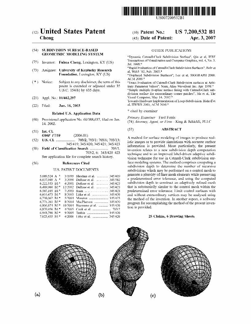
FIG. 1 schematically depicts the ordering of control points for a CCSS patch With an extraordinary vertex;
20
25
30
35
40
45
50
55
60
65
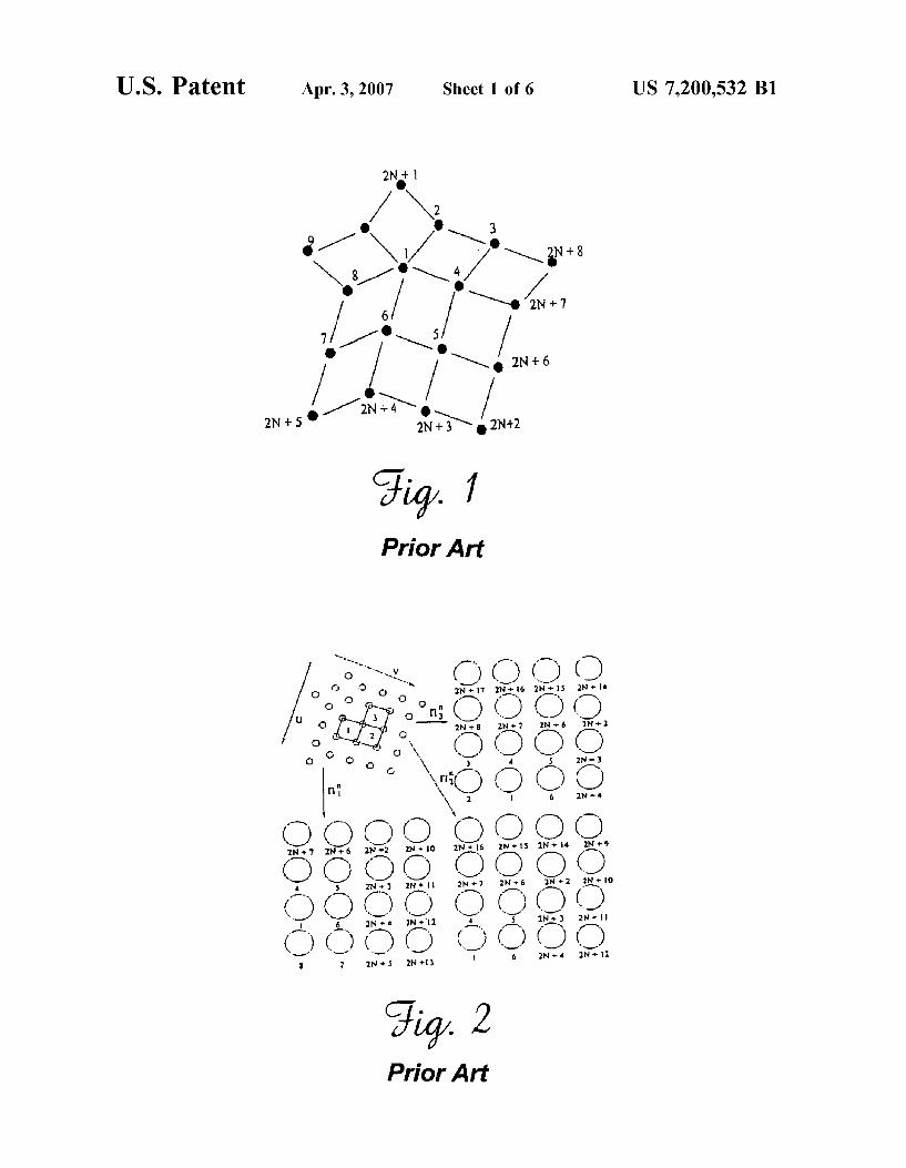
4 FIG. 2 schematically depicts a representative population
of control point sets; FIG. 3 schematically depicts the subdivision of a surface
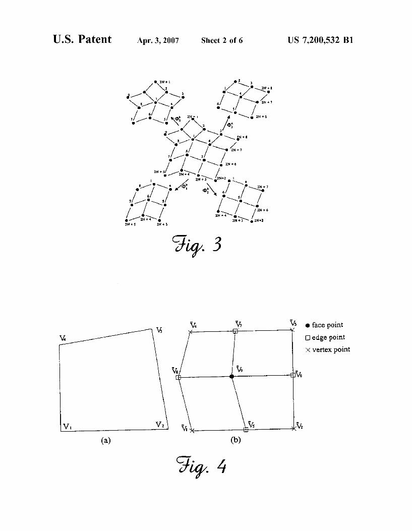
patch having an extraordinary vertex into a plurality of standard uniform bicubic B-spline surface subpatches and a single extraordinary subpatch that is not a standard uniform bicubic B-spline subpatch Which contains the limit point of the extraordinary vertex;
FIG. 4 schematically depicts FIG. 4 (aib) schematically depicts the balanced Catmull-Clark subdivision of one of the standard uniform bicubic B-spline surface subpatches of FIG. 3;
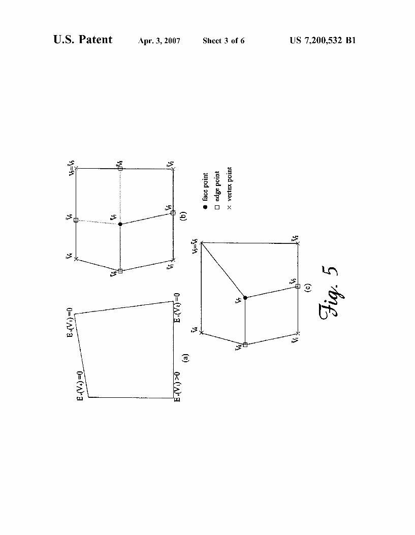
FIG. 5 schematically depicts FIG. 5 (aic) schematically depicts the unbalanced Catmull-Clark subdivision of the extraordinary subpatch of FIG. 3;
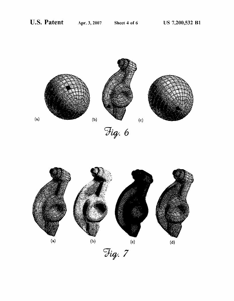
FIG. 6 (aic) depicts the distance and subdivision depth computation for a CCSS patch having: (a) no extraordinary vertex; (b) an extraordinary vertex of valence 5; and (c) an extraordinary vertex of valence 8;
FIG. 7 graphically depicts a rocker FIG. 7 (aid) graphi cally depicts a rocker arm, shoWing: (a) a control mesh therefor; (b) a limit surface therefor; (c) the result of performing a conventional uniform subdivision process; and (d) the result of performing the adaptive subdivision method of the present invention;
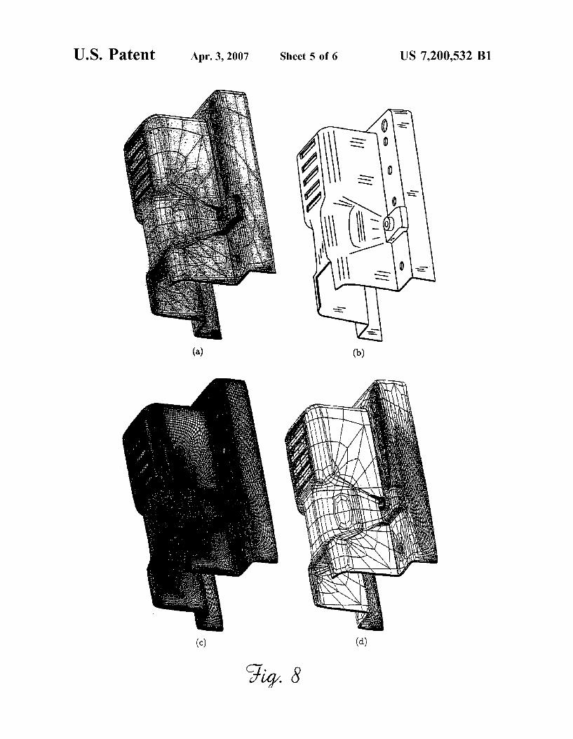
FIG. 8 (aid) depicts the distance a ventilation controller component, shoWing: (a) a control mesh therefor; (b) a limit surface therefor; (c) the result of performing a conventional uniform subdivision process; and (d) the result of perform ing the adaptive subdivision method of the present inven tion; and
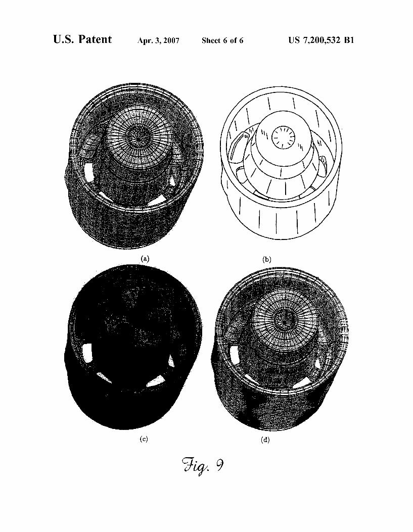
FIG. 9 (aid) graphically depicts a marker cap, shoWing: (a) a control mesh therefor; (b) a limit surface therefor; (c) the result of performing a conventional uniform subdivision process; and (d) the result of performing the adaptive subdivision method of the present invention.
DETAILED DESCRIPTION OF THE INVENTION
The present invention provides a method and computer program, Which may conveniently be disposed on a com puter readable medium, for calculating a subdivision depth for a Catmull-Clark subdivision surface (CCSS) patch, and provides also a label-driven adaptive subdivision technique for a CCSS based on subdivision depths calculated for its patches.
Subdivision Depth Computation for Patches not Near an Extraordinary Vertex. The ?rst step is computation of a subdivision depth for a
desired surface. Let V0, V1, V2, and V3 be the control points of a uniform cubic B-spline curve segment C(t) Whose parameter space is [0,1]. If the middle leg of the control polygon is parametrized as folloWs: L(t):Vl+(V2—Vl)t, Oétél, then the maximum of |\L(t)-C(t)|\ is the distance betWeen the curve segment and its control polygon. Thus:
(1)
US 7,200,532 B1 5
Since (2Vl—VO—V2)/6 and (2V2—V1—V3)/6 are the values of L(t)-C(t) at t:0 and tIl, the following lemma results:
Lemma 1: The maximum of |lL(t)-C(t)|l occurs at the end points of the curve segment and may be expressed as
Next is the step of de?ning the distance betWeen a uniform bicubic B-spline surface patch and its control mesh. Let Vl-J, 0; i,j 23, be the control points of a uniform bicubic B-spline surface patch S(u,v) With parameter space [0,l]>< [0,1]. If the central mesh face {VIM Val, V13, V23} is parametrized as folloWs:
then the maximum of |lL(u,V)—S(11,V)|l is Called the distance betWeen S(u,v) and its control mesh. De?ning Qlhk, Qvaks Q14,» and Qvk as follows:
Where Ni,3(t) are standard uniform B-spline basis functions of degree 3 results in:
Application of Lemma 1 on |\QM,I—Q4,IH, |\QM,2—Q4,2H and HQVJFQVJH, :l,2,3, and by de?ning M0 as the maximum norm of the second order forWard differences of the control
points of S(u,v), We have
MO is called the second order norm of S(u,v). From this, the folloWing lemma is derived:
Lemma 2: The maximum of |\L(u,v)-S(u,v)|l satis?es the folloWing inequality
(4)
where M0 is the second order norm of S(u, V).
20
25
30
35
40
50
55
60
65
6 It should be noted that even though the maximum of
|lL(t)-C(t)|l occurs at the end points of the curve segment C(t), the maximum of |\L(u, v)-S(u,v)|l for a surface patch usually does not occur at the corners of S(u,v). Based on the foregoing, the method for subdivision depth computation for surface patches not adjacent to an extraordinary vertex Will noW be presented.
Let V”, 0§i,j§3, be the control points of a uniform bicubic B-spline surface patch S(u,v). We use Vkl-J, Oéi, j§3+2k_l, to represent the neW control points of the surface patch after k levels of recursive subdivision. The indexing of the neW control points folloWs the convention that Vko,O is alWays the face point of the mesh face {Vk_lo,o, VI“l 1,0, VIFIOJ, Vkdhl}. The neW control points Vkl-J- Will be called the level-k control points of S(u,v) and the neW control mesh Will be called the level-k control mesh of S(u,v).
Note that if the parameter space of the surface patch is divided into 4k regions as folloWs:
9k (5)
Where 0§m,n§2k—l and let the corresponding subpatches be denoted Skm,n(u,v), then each Skm,n(u,v) is a uniform bicubic B-spline surface patch de?ned by the level-k control point set {VkP,q|m§p§m+3,n§q§n+3}. Skm,n(u,v) is called a level-k subpatch of S(u,v). One can de?ne a level-k bilinear plane Lkmm on {Vkp,qlp:m+l, m+l; q:n+l, n+2} and measure the distance betWeen Lkm,n(u,v) and Skm,n(u,v). It can be said that the distance betWeen S(u,v) and the level-k control mesh is smaller than 6 if the distance betWeen each level-k subpatch Skm,n(u, v) and the corresponding level-k bilinear plane Lkm,n(u,v), 0§m,n§2k—l, is smaller than 6. Next Will be demonstrated hoW to calculate a subdivision depth k for a given 6 so that the distance betWeen S(u,v) and the level-k control mesh is smaller than 6 after k levels of recursive subdivision. The folloWing lemma is needed in the derivation of the computation process. If We use Mkmm to represent the second order norm of 8km,” (u, v), i.e. the maximum norm of the second order forWard differences of the control points of 8km,” (u,v), then the lemma shoWs the second order norm of 8km,” (u, v) converges at a rate of 1/4 of the level-(k-l) second order norm. The proof of this lemma is provided in Appendix A.
Lemma 3: If Mk,” is the second order norm of 8km,” (u,v), then We have
(6)
where M0 is the second order norm of S(u,v).
With lemmas 2 and 3, it is easy to see that, for any 0§m,n§2k_l, We have
Osums
US 7,200,532 B1 7
Hence, if k is large enough to make the right side of (7) smaller than 6, We have
max "Limo. v) Jim. on s E Osmvsl ’ ’
for every 0§m,n§2k_l. This leads to the following:
Theorem 4: Let Via], 0§i,j§3, be the control points of a uniform bicubic B-spline surface patch S(u,v). For any given e>0, if
4411 levels of recursive subdivision are performed on the control points of S(u,v), then the distance betWeen S(u,v) and the level-k control mesh is smaller than 6 where M0 is the second order norm of S(u,v).
(3)
Subdivision Depth Computation for Patches Near an Extraordinary Vertex. A different analysis is required for computation of sub
division depth for surface patches near extraordinary verti ces, necessitated by the fact that one does not have a uniform B-spline surface patch representation and cannot use the analysis of Theorem 4 directly. The method of the present invention dictates making the siZe of such a vicinity as small as possible, thereby reducing such siZe to a degree that is tolerable (i.e., Within the given error tolerance) and use the analysis of Theorem 4 to analyZe the remaining portion of the surface patch. A subdivision depth computation based on this concept for a CCSS patch near an extraordinary vertex is presented beloW. It is assumed that the initial mesh has been subdivided at least tWice such that each mesh face is a quadrilateral and contains at most one extraordinary vertex.
Let HOO:{Vl-|1§i§2N+8} be a level-0 control point set that in?uences the shape of a surface patch S(u,v) (:SOO(u, V). V1 is an extraordinary vertex With valence N. The control vertices are ordered folloWing Stam’s fashion (Stam, J. 1998. Exact Evaluation of Catmull-Clark Subdivision Sur faces at Arbitrary Parameter Values. In Proceedings of SIGGRAPH 1998, 3954404, incorporated herein by refer ence) as schematically depicted in FIG. 1.
Using V’qi to represent the level-n control vertices gener ated after n levels of recursive Catmull-Clark subdivision, and use 8%, S”1, S”2 and S”3 to represent the subpatches of 8”‘1O de?ned over the tiles
respectively, then the shape of S”O, S'ql, S”2 and S”3 are in?uenced by the level-n control point sets TI”O, H'ql, TI”2, and IT”3 are depicted in FIG. 2.
S'ql, S”2 and S”3 are standard uniform bicubic B-spline surface patches because their control meshes satisfy a 4-by-4
20
25
30
35
40
45
50
55
60
65
8 structure. Hence, the technique described in Theorem 4 can be used to compute a subdivision depth for each of them. S”O is not a standard uniform bicubic B-spline surface patch. Hence, Theorem 4 can not be used to compute a subdivision depth for S”O directly. For convenience S”O may be called a level-n extraordinary subpatch of S(u,v) because it contains the limit point of the extraordinary points (see beloW). Note that if HO and H” are column vector representations of the control points of H00 and TI”O, respectively,
HOE(VO,V1, . . . ,V2N+8)’,H,,E(VO", V1", . . . ,V2N+8")’
where Q(, X, . . . , X)’ represents the transpose of the roW
vector Q(, X, . . . , X) then We have
HFUYHO (9)
Where T is the (2N+8)><(2N+8) (extended) subdivision matrix de?ned as folloWs:
(10)
With
HIV b/\/ 0N b/\/ 0N b/\/ ' b/\/ 0N (11)
d d e e O 0 e e
f f f f 0 0 0 0
i d e e d e e O O
T: f 0 0 f f f 0 0’
d e O O O 0 d e
f f O O O O f
c O 0 ba b0 0 O (12)
e O O eddO O O
b O O c b ab 0 0
TM: 2 O O O 0 d d e 0,
e O O dd 2 O O O
b c b ab 0 O O 0
e eddO O O O O
c b c O b c O (13)
0 e e O O O O
O c b c O O O
Th2: O 0 e e O O O
O O O 0 e e O
O O O O c b c
O O O O 0 e e
and
7 3 1 9
aN=1—m,bN=W,cN W,Q=E,
b:3,,:_,d:§,,:i,f:1 32 64 8 16 4

US 7,200,532 B1
Subdivision Depth Computation for a Vicinity of the Extraordinary Vertex.
The goal is to ?nd an integer n6 for a given 6>0 so that if n (im) recursive subdivisions are performed on H0O, then the control set point of the level-n extraordinary subpatch S”O of S(u,v), H'qO:{V”l-|l§i§2N+8}, is contained in the sphere B(V "+15, 6/2) With center V”+15E(V”1+V”4+V”5+ V”6)/4 and radius 6/2. Note that if the (2N+8)-point control mesh is contained in the then the level-n extraordinary subpatch S”O is contained in the sphere B(V”+l5, 6/2) as Well. This folloWs from the fact that S”O, as the limit surface of TI”O, is contained in the convex hull of TI’qO and the convex hull of H'qO is contained in the sphere B(V "+15, 6/2). Then, We have
maxHSO"(u,v)—LO"(u,v)H<6 (14)
Where L”O(u,v) is a bilinear plane de?ned on the level-n mesh face {V'ql+V”4+V”5+V”6}. The construction of such an n6 depends on several properties of the (extended) subdivision matrix T and the control point sets {11%}.
First note that since all the entries of the extended subdivision matrix T are non-negative and the sum of each roW equals one, the extended subdivision matrix is a tran sition probability matrix of a (2N+8)-state Markov chain. In particular, the (2N+l)><(2N+l) block T* of T is a transition probability matrix of a (2N+l)-state Markov chain. The entries in the ?rst roW and ?rst column of T* are all non-Zero. Therefore, the matrix T* is irreducible because (T *)2 has no Zero entries and, consequently, all the states are accessible to each other. On the other hand, since all the diagonal entries of T* are non-Zero and entries of (T *)” are non-Zero for all n22, it folloWs that all the states of T* are aperiodic and positive recurrent. Consequently, the Markov chain is irreducible and ergodic. By the Well-knoWn theorem of Markov chain, Theorem 4), (T *)” converges to a limit matrix T* Whose roWs are identical. More precisely
Where A1. are the unique non-negative solution of
with tn]. being the entries of T*. One can easily get the folloWing observations.
The vector (A1, A2, . . . , Azml) satis?es the folloWing
20
25
30
35
40
45
50
55
60
10
-continued
The matrix T* is an idempotent matrix, i.e. T* T*:T*. Hence, T* has tWo eigenvalues, l and 0 (With multi plicity 2N).
T* has 1 as an eigenvalue and all the other 2N eigenvalues of T* have a magnitude smaller than one.
As is Well knoWn, the limit point of {V1} is
But V*l is actually the limit point of all V'qj, jIl, 2, . . . , 2N+8. Therefore, the convex hull of {V'qp V”2, . . . , V”2N+8} converges to V* 1 When n tends to in?nity and, consequently, V*1:S(0,0). The fact that V*l is the limit point of {V”1, V”2, . . . , V”2N+l} folloWs from (9) and (15). The fact that V*l is also the limit point of {V”2N+2, V”2N+3, . . . is demonstrated in Appendix B. The last observation is important because it shoWs that
maxuvytl - v|| <17) V6118
converges. Therefore, it is possible to reduce the siZe of S”O to a degree that is tolerable if n is large enough. For a given 6>0 We Will ?nd an n6 so that if nin6 then the level-n control point set H'qO is contained in the sphere B(V "+15, 6/2). To do this, We need to knoW hoW fast (17) converges.
Referring to FIG. 3, let (DkO, (Dkl, (D2, and (D13, be subsets of 11% de?ned as folloWs:
(V kg in @kl should be replaced With Vk2 if NI3) and de?ne Gko, Gkl, G2, and Gk3 as folloWs:
Gkl. is called the ?rst order norm of (Dki, iIO, l, 2, 3. We need the folloWing lemma for the construction of n6. The proof is shoWn in Appendix C.
Lemma 5: If (Dkl- and Gkl- are de?ned as above, then for iIO, 1,2, 3,We have
(20)
Where Gosmax {GOO, G01, G02, G03}. G0 is called the ?rst order norm of H00.
To construct n6, note that if V611”O and V6(I>”O, We have
US 7,200,532 B1 11
It is easy to prove that similar inequalities hold for (I>”1, (I>”2, and (I>”3 as Well. Hence, for each VeH'qO, by Lemma 5 We have
Since the maximum of 3A1+7A1N—13/2N2 occurs at N:7, (21) can be simpli?ed as
7 1 n (22) Vn+1_ V _ _[_] G0 ll 5 ll < 4 6
Where
4-1 if N —3 (23) 6- 3, — _ 98
g, if N 25
Hence, |\V”+15—V|\ is smaller than 6/2 if n is large enough to make the right hand side of (22) smaller than or equal to 6/2. Consequently, We have the following theorem.
Theorem 6: Let HOO:{Vi|1§i§2N+8} be a level-0 control point set that in?uences the shape of a CCSS patch S(u,v) (:SOO(u,v)). V1 is an extraordinary vertex With valence N. The control vertices are ordered folloWing Stam’s fashion. For a given e>0, if n6 is de?ned as folloWs:
4 , (24) 7G0 g If N =3
"651M611 98 5, if N 25
where G0 is the ?rst order norm of H00, then the distance betWeen the level-n extraordinary subpatch S”O(u,v) and the corresponding bilinear plane L”O(u,v) is smaller than or equal to e if ning Theorem 6 shoWs that the rate of convergence of the control mesh in the vicinity of an extraordinary vertex is fastest When valence of the extraor dinary vertex is three.
Subdivision Depth Computation for the Remaining Part. It is desired, for each k betWeen 1 and n6, to determine a
subdivision depth Dk (im) so that if Dk recursive subdivi sions are performed on the control mesh H0O of S(u,v), then the distance betWeen the level-Dk control mesh and the subpatches Ski, i:1, 2, 3, is smaller than 6. Consequently, if We de?ne D to be the maximum of these Dk(i.e. D:max {Dk|1§k§n€}), then after D recursive subdivisions, the distance betWeen the level-D control mesh and the sub patches Ski, i:1, 2, 3, Would be smaller than 6 for all 1 ékéng Note that the distance betWeen the level-D control mesh and the subpatches Skl, S2, and Sk3 for n€+1§k§D, and the distance betWeen the level-D control mesh and the level-D extraordinary subpatch SDO Would be smaller than 6 as Well. This is because these subpatches are subpatches of
20
25
30
35
40
45
50
55
60
65
12 Sn‘O and the distance betWeen Sn‘O and the level-n6 control mesh is already smaller than 6. Hence, the key here is the construction of Dk. We Will shoW the construction of Dk for Sk3 (u,v). This Dk Works for Skl (u,v) and Sk2 (u,v) as Well.
For Oéu, vél, de?ne a bilinear plane Lk3 (u, v) on the mesh face {V2, Vks, Vk2N+7, Vk2N+6} as folloWs:
Since Sk3(u, v) is a uniform bicubic B-spline surface patch With control mesh 11%, We have, by Lemma 2,
Where Zk3 is the second order norm of Sk3 (u,v). If We de?ne Zl-O to be the second order norm of Sio(u,v), We have
The proof of (27) is shoWn in Appendix D. Hence, by combining the above results, We have
Lemma 7 The maximum distance betWeen Sk3 and Lk3 satis?es the folloWing inequality
m?XllL3k(14,\/)—S3k(14,v)llé 1/3( WY’ZOO (29)
Where W is de?ned in (28) and Z0O is the second order norm of S(u,v).
It should be pointed out that When de?ning Zio, only the folloWing items are needed for second order forWard differ ences involving Vil:
Lemma 7 shoWs that if 1/3(W)k Zooée then the distance betWeen Sk3 and Lk3 is already smaller than 6. HoWever, since n6 subdivisions have to be performed on H0O to get S“O anyWay, Dk for Sk3 in this case is set to n6. This condition holds for Skl and Sk2 as Well.
If 1/3(W)k ZOO>e, further subdivisions are needed on Hki, i:1, 2, 3, to make the distance betWeen Ski, i:1, 2, 3, and the corresponding mesh faces smaller than 6. Considering Sk3 again, Sk3 is a uniform bicubic B-spline surface patch With control mesh 1113. Therefore, if 1k recursive subdivisions are performed on the control mesh 11%, by Lemma 2 and Lemma 3 We Would have
llL3’k(14,\/)—S3k(14,v)ll§%(%)”‘Z3k (30)
Where LU“3 (u,v) is a level-1k control mesh relative to 11k3 and Zk3 is the second order norm of Sk3(u, v). Therefore, by combining the above result With 27), We have
We get the folloWing Lemma by setting the right hand side of (31) smaller than or equal to e.
US 7,200,532 B1 13
Lemma 8 In Lemma 7, if the distance between Sk3 and Lk3 is not smaller than 6, then one needs to perform 1k
(WW8 14104 3. ll
more recursive subdivisions on the level-k control mesh ITk3 of Sk3 to make the distance between Sk3 and the level-(k+lk) control mesh smaller than 6.
This result works for for Skl and Sk2 as well. Note that the value of (W)k Z0O is already computed in Lemma 7 and W hs to be computed only once. Therefore, the subdivision depth Dk for Skl, S2, and Sk3 is de?ned as follows:
Consequently, we have the following main theorem:
Theorem 9 Let ITOO:{Vi|l §i§2N+8} be the control mesh of a CCSS patch S(u,v). The control points are ordered fol lowing Stam’ s fashion with Vl being an extraordinary vertex of valence N (see FIG. 1). For a given e>0, if we compute n6 as in (24) and D as follows:
(32)
(33)
D:max {Dkll ékénd (34)
where Dk is de?ned in (33) then after D recursive subdivi sions, the distance between S(u,v) and the level-D control mesh is smaller than 6.
Label-Driven Adaptive Subdivision Given a control mesh of arbitrary topology and an error
tolerance e>0, the next step is to construct an adaptively re?ned mesh that is close to within 6 to the CCSS of the given control mesh, but with signi?cantly fewer faces than are derived from the traditional Catmull-Clark subdivision process. The mesh re?ning process is driven by labels of mesh vertices.
The given control mesh will be referred to as E0 with the assumption that all the faces are quadrilaterals and each face contains at most one extraordinary vertex (as described supra). The limit surface of 20 will be referred to as F. For each positive integer k, 2k refers to the result of applying k levels of recursive Catmull-Clark subdivision on 20. A face of 2k is called an interior face if it is not adjacent to the boundary of the mesh. Otherwise, it is called an exterior face. All the faces of a closed control mesh are interior faces. Each interior face f of Y“ has a corresponding surface patch in F, denoted Sf. The interior faces and their corresponding surface patches are parametriZed using the techniques pre sented by Stam. The distance between f and the limit surface F is de?ned as the distance between f and the corresponding surface patch Sf The initial label of an interior face f in E0, denoted L/(f),
is set to k if k is the subdivision depth of the corresponding surface patch Sf with respect to e. The label of an exterior face is set to Zero. The label of a vertex V in Z0 is de?ned as the maximum of labels of adjacent faces, i.e.,
Lv(V):rnax {LmfeEO and Vis a vertex off}. (35)
The adaptive re?nement procedure requires vertex labels of Z0 to satisfy the consistent condition (Cheng, P. et al., 1989. A Parallel Mesh Generation Algorithm Based on the Vertex Label Assignment Scheme. International Journal for
20
25
30
35
40
45
50
55
60
65
14 Numerical Methods in Engineering 28, l429il448, incor porated herein by reference). A face of Z0 is said to be an illegal face if two adjacent vertices have non-Zero labels and two adjacent vertices have Zero labels. The vertex labels of Z0 are said to satisfy the consistent condition if 20 contains no illegal faces. The consistent condition ensures that the adaptively re?ned meshes are crack-free. Usually, 20 does not satisfy the consistent condition. The easiest way to make 20 satisfy the consistent condition is to set all the Zero labels to 1. However, this would unnecessarily increase the number of faces generated in the resulting meshes since the number of faces in the re?ned meshes is determined by the labels of the vertices. A better way is to construct an extension
function EV(V) of LV(V),
MW), if MW) > 0;
O or 1, if 14W) :0,
which satis?es the consistent condition but with as many Zero labels as possible.
A greedy algorithm for the construction of EV(V) via a connection supporting graph G17 is therefore presented herein. The vertices of G17 are those of the illegal faces whose labels are Zero. The edges of G17 are those of E0 that connect vertices of G1,. The extension function EV(V) is constructed by repeatedly selecting a vertex from Gb, changing its label to l and then updating Gb accordingly. This process contin ues until G17 is empty. The complexity of this process is that changing the label of a vertex from 0 to 1 changes the status of adjacent faces: an illegal face might become legal and a legal face might become illegal. Therefore, after changing the label of a selected vertex from 0 to 1, one needs to remove some old vertices and edges from G17 while adding some new vertices and edges into Gb. Obviously, the greedy algorithm should remove as many old vertices from G17 and add as few new vertices into G17 as possible during each selection and changing cycle. This is achieved by using the following rule in selecting a vertex from G17 to change label. Let D(V) denote the degree of V in Gb and let N(V) be the number of new vertices introduced into G17 if the label of V is changed from 0 to 1. If the number of D(V):l vertices is not Zero then, in the pool of vertices which are adjacent to a D(V):l vertex, select any one with a minimum N(V) among those with a maximum D(V). Otherwise, select any vertex with a minimum N(V) among the vertices of G17 with a maximum D(V). The adaptive subdivision process is driven by vertex
labels and is performed on individual mesh faces indepen dently. After each subdivision step, labels are assigned to the newly generated vertices so they can drive the next subdi vision step. The resulting meshes are crack free. The assumption is made that labels of the vertices of Z0 are de?ned by an extension function Ev even though the exten sion function might be the same as the original label function Lv. In the following, 2k, kIl, 2, . . . , stand for the meshes generated by the adaptive re?nement process. Also, vari ables without a bar refer to elements in Zk_1, and variables with a bar refer to elements in 2]“.
The adaptive subdivision of Elf-1, kil, is performed as follows. If a face has two or more nonZero vertex labels, a balanced Catmull-Clark subdivision is performed on that face (see FIG. 4). A balanced Catmull-Clark subdivision is a standard Catmull-Clark subdivision. However, coordinates of the new vertices are not yet computed. The new vertices are marked for updating. Labels of the new vertices are
US 7,200,532 B1 15
de?ned as follows. For each new vertex point, Evwl-Fmax {0, Ev(Vl.)—1}, i:1, 2, 3, 4. For each new edge point, E1?) is the minimum of labels of the new vertex points adjacent to V1, i:5, 6, 7, 8. For the new face point,
If a face has only one vertex with nonZero label, an unbalanced Catmull-Clark subdivision with respect to that vertex is performed (see FIG. 5). An unbalanced Catmull Clark subdivision generates three new faces only, as shown in FIG. 50. However, V8, V9 and the auxiliary structure shown in FIG. 5b are computed and recorded for use in the computation of the vertices of Y‘“. Again, coordinates of the new vertices are not computed until a later point. The vertices, except V3, are marked for updating and later evaluation. The labels of the new points are set to Zero
except V1 which is de?ned as EvWl):Ev(Vl-)—1. The faces without non-Zero vertex labels are not further adaptively subdivided, but are inherited topologically.
After all the faces of Zk_l are processed, vertices marked for updating in Y“ are computed using the Catmull-Clark subdivision scheme to ?nd their coordinates in 2k. Note that the vertices of Zk_l required in the computation process for the new vertices are available because they were stored with the auxiliary structure (see FIG. 5b) even though not output. Other vertices (vertices marked for updating) of Y“ are inherited from Zk_l directly. Keeping an “update” status for some of the vertices in the adaptive subdivision process is necessary because whether a vertex should be inherited or updated depends on its adjacent faces. The adaptive re?ne ment process stops when labels of all the new vertices are ZeI'O.
40 Other aspects of the present invention will become appar
ent to those skilled in this art from the following description wherein there is shown and described a preferred embodi ment of this invention, simply by way of illustration of one of the modes best suited to carry out the invention. As it will 45 be realiZed, this invention is capable of other different embodiments and its several details are capable of modi? cation in various, obvious aspects all without departing from the intended scope of the invention. Accordingly, the descriptions and examples herein will be regarded as illus trative in nature and not as restrictive.
50
EXAMPLE 1
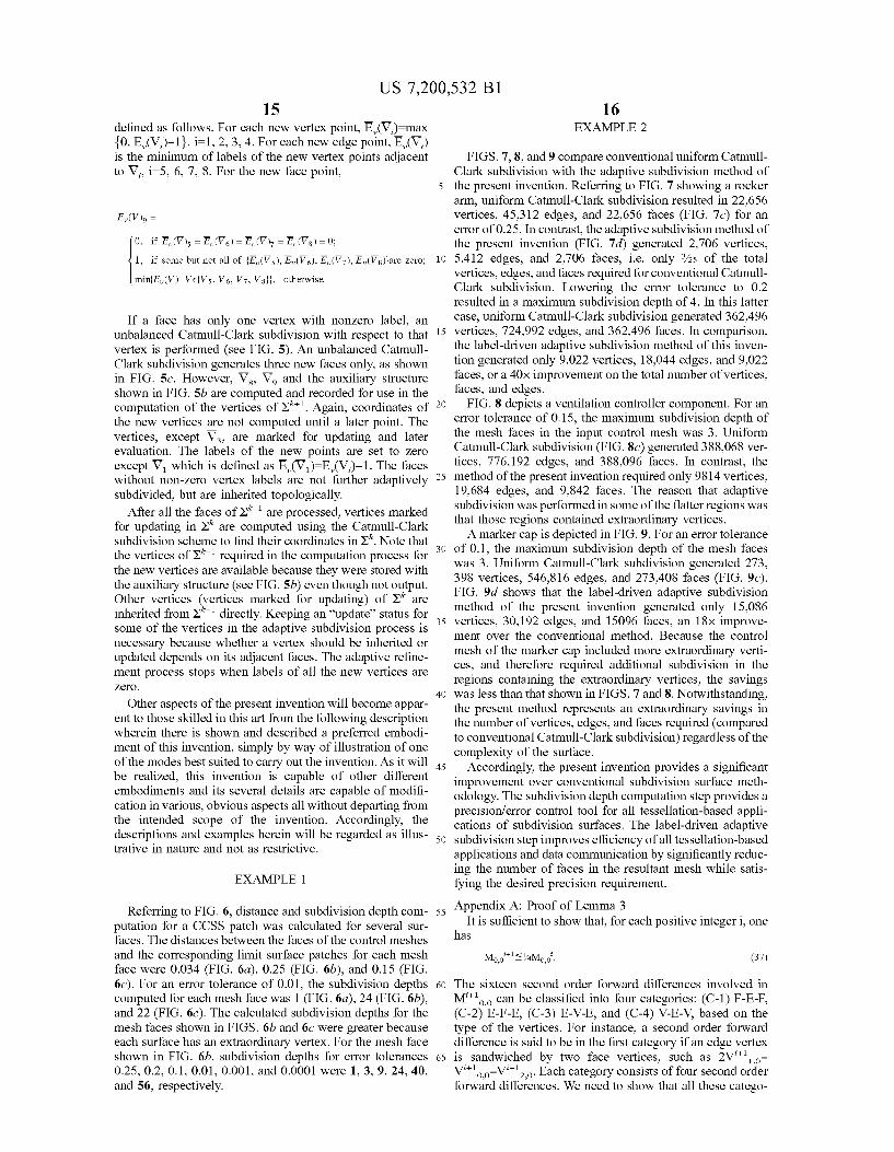
Referring to FIG. 6, distance and subdivision depth com putation for a CCSS patch was calculated for several sur faces. The distances between the faces of the control meshes and the corresponding limit surface patches for each mesh face were 0.034 (FIG. 6a), 0.25 (FIG. 6b), and 0.15 (FIG. 60). For an error tolerance of 0.01, the subdivision depths computed for each mesh face was 1 (FIG. 6a), 24 (FIG. 6b), and 22 (FIG. 60). The calculated subdivision depths for the mesh faces shown in FIGS. 6b and 60 were greater because each surface has an extraordinary vertex. For the mesh face shown in FIG. 6b, subdivision depths for error tolerances 0.25, 0.2, 0.1, 0.01, 0.001, and 0.0001 were 1, 3, 9, 24, 40, and 56, respectively.
60
65
16 EXAMPLE 2
FIGS. 7, 8, and 9 compare conventional uniform Catmull Clark subdivision with the adaptive subdivision method of the present invention. Referring to FIG. 7 showing a rocker arm, uniform Catmull-Clark subdivision resulted in 22,656 vertices, 45,312 edges, and 22,656 faces (FIG. 70) for an error of 0.25. In contrast, the adaptive subdivision method of the present invention (FIG. 7d) generated 2,706 vertices, 5,412 edges, and 2,706 faces, i.e. only 3/25 of the total vertices, edges, and faces required for conventional Catmull Clark subdivision. Lowering the error tolerance to 0.2 resulted in a maximum subdivision depth of 4. In this latter case, uniform Catmull-Clark subdivision generated 362,496 vertices, 724,992 edges, and 362,496 faces. In comparison, the label-driven adaptive subdivision method of this inven tion generated only 9,022 vertices, 18,044 edges, and 9,022 faces, or a 40x improvement on the total number of vertices, faces, and edges.
FIG. 8 depicts a ventilation controller component. For an error tolerance of 0.15, the maximum subdivision depth of the mesh faces in the input control mesh was 3. Uniform Catmull-Clark subdivision (FIG. 80) generated 388,068 ver tices, 776,192 edges, and 388,096 faces. In contrast, the method of the present invention required only 9814 vertices, 19,684 edges, and 9,842 faces. The reason that adaptive subdivision was performed in some of the ?atter regions was that those regions contained extraordinary vertices. A marker cap is depicted in FIG. 9. For an error tolerance
of 0.1, the maximum subdivision depth of the mesh faces was 3. Uniform Catmull-Clark subdivision generated 273, 398 vertices, 546,816 edges, and 273,408 faces (FIG. 90). FIG. 9d shows that the label-driven adaptive subdivision method of the present invention generated only 15,086
5 vertices, 30,192 edges, and 15096 faces, an 18>< improve ment over the conventional method. Because the control mesh of the marker cap included more extraordinary verti ces, and therefore required additional subdivision in the regions containing the extraordinary vertices, the savings was less than that shown in FIGS. 7 and 8. Notwithstanding, the present method represents an extraordinary savings in the number of vertices, edges, and faces required (compared to conventional Catmull-Clark subdivision) regardless of the complexity of the surface.
Accordingly, the present invention provides a signi?cant improvement over conventional subdivision surface meth odology. The subdivision depth computation step provides a precision/error control tool for all tessellation-based appli cations of subdivision surfaces. The label-driven adaptive subdivision step improves e?iciency of all tessellation-based applications and data communication by signi?cantly reduc ing the number of faces in the resultant mesh while satis fying the desired precision requirement.
Appendix A: Proof of Lemma 3 It is su?icient to show that, for each positive integer i, one
has
Mowo’u'lél?aMoyoi. (37)
The sixteen second order forward differences involved in M1110,O can be classi?ed into four categories: (C-l) F-E-F, (C-2) E-F-E, (C-3) E-V-E, and (C-4) V-E-V, based on the type of the vertices. For instance, a second order forward difference is said to be in the ?rst category if an edge vertex is sandwiched by two face vertices, such as 2Vi+ll,o— Vi+lO,O—Vi+l2,O. Each category consists of four second order forward differences. We need to show that all these catego
US 7,200,532 B1 17 18
ries satisfy (37). In the following, We prove (37) for one item Where T* is de?ned in (15) and T* 1,1 is a 7><(2N+l) version of each category. The proof of the other items is similar. of T*, i.e.
(F-E- F) ; consider avg; - V551 - v3}. (38) 5 A1 A2 AZNH (43)
Ca, A1 A2 A21v+1 1+1 1+1 1+1 1 i i i T111 : : - ' ’
"ZN/0,1 — V0,2 — V0,0 H = “gal/0,1 — V0,2 — V0,0) + ' '
l . . . A1 A2 AZNtl 7><(2N+l)
§(2Vi,1 — Vi,2 — Vi,0) 5 10
1M‘. 1M. _ 1M‘. § 0'0 + § 010 _ Z1 010' then, by (9) We have
Vj"—>V1*EA1V1+A2V2+ . . . +A2N+1V2N+1
Case 1 15 for j:2N+2, 2N+3, . . . , 2N+8. Hence, to prove that
V”2N+2, . . . ,V”2N+8 converge to V*l, it is su?icient to show
(5_ F_ E);consider 2vé+21_vé+31_ vé+l1_ (39) that (42) is true, or, equivalently, to shoW that (i) (T l,2)” converges to a 7x7 Zero matrix When 11 tends to in?nity, and (ii) the loWer-left 7><(2N+l) block of (T)2” converges to
uzvaal-vael- 51111=H—<2va2-v<s3-va1+2va1-v<s2-v<s0+ _ . . . . ' ' ' 16 ' ' ' ' ' ' 20 T*l,l. (I) is obvious because T1,2 contains non-negative
ZVi? — Vl,3 — Vl,1 + Zv?l — V1‘) — Vl,0)|| 5 entries and the sum ofeach roW is smaller than one. To prove
1 . 1 . 1 . 1 . 1 _ (ii), note that the sum of each roW of (7)” is one and, from
EM6,O+EM6,O+EM6,O+EM6,O= zMép- (i), (T1,2)n_)0
25
Case 2 Therefore, for each of the last 7 roWs of (T)”, the sum of the ?rst 2N+l entries is close to one When n is large. On the other hand, When n is large, (15) is true, ie each column of
(E — V — E) I Consider Zvl?l — Vial — VlIol- (40) @‘4 has almost identical entries. Hence, computing an entry
30 of the loWer-left 7><(2N+l) block of (T)2”:(T)”(T)” is like multiplying 2N+l almost identical entries (in the same column of the upper-left (2N+l)><(2N+l) block of the sec ond (T)” by 2N+l non-negative numbers Whose sum is close to one (in the same roW of the loWer-left 7><(2N+l) block of
35 the ?rst (T)”. Consequently the value of that entry in the loWer-left 7><(2N+l) block of (T)2”:(T)” (T)” is close to the
S
iMé-m + iMéo + iMéo : {M60 ?rst 2N+l almost identical entries in the same column ofthe 32 ' 16 ' 32 ' 4 ' second (T)” and this completes the proof of (ii).
C 3 40 Appendix C: Rate of Convergence of (Dkj ase In this appendix We prove Lemma 5. Since (Dkj is sym
metric to CD13, We only need to consider Gko, G2, and Gk3 , . . . for the lemma.
(V — E- V) : consider 2V1‘;l — Vfgl — Vl‘jl. (41) _
(i) Gko. For an edge point such as Vl+l4, We have 1 45
||2Vi,+2l _ Vi? _ vifll|| = “@(zvdz — V63 — V64 + zvdl — V61 — 3 . l . l N 3 . . N 1 . (44)
_ _ _ _ 1+ 1+ _ — l I _ l — l _ _
V0,0) + 5W1; — Vi,3 — Vi,1 +2Vi,1— "V1 _ V4 H _ j; ZNZWZJ V1) +1; 4N2(V2J+1
v‘ v‘ ) 1 (2v‘ v‘ v‘ 50 3 1 1 1,2—1,0+— 2,2— 2,3— 2,1+ i ___ i_i __ 64 1 1 v1)+[2N2 161% Vl)+[4N2 2V” _ V22 _ V20)" 5 [a + a + i + i)(v" - v") + (i — 31W‘ - v") + 311.1. 16312N2841
i + Q + @lMNO : ZMOYO' 1 1 V. V. 3 1 V. 55 [W—E](5_ I)+[W_EJ(G_
Case 4 . N 3 N 1 3
_ Vi||sZ2—2+Z4—2+‘[2N2 This completes the proof of the lemma. 1:4 1:3
Appendix B: Convergence of V”2N+2, . . . , V”2N+8 60 +[E _ +2[i 1 HG‘O _ l6 8 2 2 l6 4N2
Note that if one can prove that 3 7 4
_ [§+W—W]G‘O, 1fN=3 _ 5 7 10 .
T 0 " T 0 (42) (_+___2]c;,, ifNzS lim(T)”= lim i i =T*E H 65 8 4N n?oo n?oo T11 T12 T111 0
Where Gl-O is de?ned in (20).
US 7,200,532 B1 19
For a face point such as Vi+1 3, We have
(45)
10
41v2 4 312N2 4 41_;21\/2
N 1 2(1 3 J 1 1 G‘. gw+ Z-WH-FW 0- 15
(3+ 7 131G‘ 1v-3 1v>5 4 41v 2N2 0’ ‘or _'
20
The other cases are similar to (44) or (45). Hence, We have the following inequality for N:3 or N25:
. 25
GM [3 7 13 J i [3 7 13 I“ 0 (46) < - _ -— < - _ -—
° —4+41v 2N2 0- 4+41v 2N2 0'
(ii) Gk3. For an edge point such as Vi+1 2N+8, We have 30
i i 1 i i i i 5 i i (47) ||v4*1— V2128" = HBO/2M + V21v+7 — v6 — v5) + EM — v1) 5
1 i i 1 i i 1 i i 35
“E(V2N+8 — V4) + EU/ZNH _ V4) + E(V4 — V6) +
1 i i 5 i i 9 i i
Em - v5) + Em - v1) 5 Rmax{(;o, G3}
40
Where G1-0 and Gl-3 are de?ned in (20). For a face point such as Vi+1 3, We have
45 i i 3 i i 1 i i 1 i i (48)
||v4*1- v3*1||=“E(v2 + v3) - Em, + V,) - g(v1+ v4) 5
3 i i 3 i i 1 i i 1 i i “EU/2 _ V1) + EW3 _ V4) + E(V1_ V6) + EW4 _ V5) 5
1 . . 50
—maX{G‘O, G5}. 2
For a Vertex point such as Vi+1 2N+7, We have
55
Ml — 511.71 = <49)
3 i 9 i 1 i i 3 i 3 i i
“Eb/4 — 5V1 + 5W3 + V5) + ivzlvn — @045 + V2) +
1 . . 60
@Wz‘ms + V2N+6) 5
1 i i 3 i i 1 i i
“a(V2N+8 — V4) + ?wzlvn — V4) + a(V2N+6 — V4) +
65
20
The other cases are similar to these cases. Hence, by combining the results of (47), (48), and (49), We have
The second inequality of (50) folloWs from (46). (50) Works for N:3 or N25.
(iii) Gkz. For an edge point such as Vi+12N+6, We have
The other cases are similar to these tWo cases. Hence, by combining the results of (51), (52), (46), and (50), We have
Where GOImaX {GOO, G01, G02, G03}. The lemma noW folloWs from (46), (50), and (53).
Appendix D: Proof of (27) The proof of Lemma 3 shoWs that the norms of most of
the second order forWard differences of the control points of Hk3 satisfy the inequality
VkZNH. The last tWo cases are similar. Hence, We only need consider the ?rst tWo cases.

US 7,200,532 B1 21
In the second case, We have
S
Where Zl-O is _the second order norm of $0. In the above derivation, V18 should be replaced With V12 When NI3.
In the ?rst case, When N25, We have
2 16N F1
In the ?rst summation, one should use VZIZN+1 for Viz].+1 When jIl. The difference betWeen the case N:5 and N26 comes from the fact that (N2—28) is negative When N:5. When NI3, We have
Consequently, from the above results We have the ?rst part of (27). The second part of (27) folloWs from the observation that the norms of second order forWard differences similar to 2Vl"'l1—Vl'+12—Vi+16 dominates the other second order for Ward differences in all subsequent norm computation.
The foregoing description is presented for purposes of illustration and description of the various aspects of the invention. The descriptions are not intended to be exhaustive or to limit the invention to the precise form disclosed. The embodiments described above Were chosen to provide the
20
25
30
35
45
50
55
22 best illustration of the principles of the invention and its practical application to thereby enable one of ordinary skill in the art to utiliZe the invention in various embodiments and With various modi?cations as are suited to the particular use contemplated. All such modi?cations and variations are Within the scope of the invention as determined by the appended claims When interpreted in accordance With the breadth to Which they are fairly, legally and equitably entitled.
What is claimed is: 1. A method for modeling or representing a surface or
shape having an arbitrary topology Which may be repre sented by a control mesh comprising at least one discrete Catmull-Clark Subdivision Surface (CCSS) patch de?ned by a set of control points, comprising the steps of:
computing a subdivision depth determining the number of recursive subdivisions Which may be performed on the control mesh to generate a plurality of ?ner mesh elements, Whereby a distance betWeen each ?ner mesh element and a corresponding limit surface patch is less than a predetermined error tolerance e; and
using the computed subdivision depth to construct an adaptively re?ned mesh that is substantially similar to the control mesh Within the range of said predetermined error tolerance 6;
wherein each face of the recursively subdivided control mesh is a quadrilateral and contains up to one extraor dinary vertex.
2. The method of claim 1, Wherein the limit surface patch is not adjacent to an extraordinary vertex.
3. The method of claim 1, Wherein the limit surface patch is adjacent to an extraordinary vertex.
4. The method of claim 2, Wherein the limit surface patch is a uniform bicubic B-spline surface patch designated S(u,v).
5. The method of claim 4, including the step of calculating a subdivision depth k de?ned as k levels of recursive subdivision performed on the control points of the limit surface patch S(u, v) to generate a level k control mesh, Wherein k is de?ned as kZI log4 (MO/36)], where M0 is the second order norm of S(u,v) and the distance betWeen S(u,v) and the level k control mesh is less than 6.
6. The method of claim 3, including the initial step of subdividing the limit surface patch at least tWice to de?ne at least one standard uniform bicubic B-spline surface sub patch and up to one extraordinary subpatch that is not a standard uniform bicubic B-spline subpatch, said extraordi nary subpatch containing a limit point of up to one extraor dinary vertex.
7. The method of claim 6, further including the step of computing a subdivision depth n6 for the extraordinary subpatch, de?ned as n levels of recursive subdivision per formed on the extraordinary subpatch to generate a level n extraordinary subpatch control mesh, Wherein n6 is de?ned as
where G0 is the ?rst order norm of H00, H00 is a level-0 control point de?ned as {VI-ll §i§2N+8}, V1- is an extraor dinary vertex With valence N, and the distance betWeen the level n extraordinary subpatch control mesh and a corre

US 7,200,532 B1 23
sponding bilinear plane de?ned in the extraordinary sub patch is less than or equal to e if n§n€
8. The method of claim 7, further including the step of computing a subdivision depth D by performing D recursive subdivisions on each standard uniform bicubic B-spline subpatch to de?ne a level D control mesh, Wherein D is de?ned as the maximum number of recursive subdivisions Which may be performed such that the distance betWeen the standard uniform bicubic B-spline subpatch and the level D control mesh is less than 6.
9. The method of claim 1, Wherein the step of constructing an adaptively re?ned mesh comprises the steps of:
de?ning a mesh for Which subdivision depths have been computed, said mesh comprising a plurality of quad rilateral faces containing up to one extraordinary vertex and having at least one interior face not adjacent a boundary of the control mesh and at least one exterior face adjacent a boundary of the control mesh;
de?ning an initial label of the interior face as a non-Zero integer k Wherein k is the subdivision depth of its corresponding surface patch With respect to e,
de?ning an initial label of the exterior face as Zero;
establishing a consistent condition for each face Whereby no tWo adjacent vertices thereof have non-Zero labels and no tWo adjacent vertices thereof have Zero labels and further Wherein the number of Zero labels is maximiZed, the consistent condition being established by de?ning a connection supporting graph G17 Whose vertices are those of the faces having tWo adjacent vertices Whose labels are Zero, selecting a vertex from Gb, rede?ning the selected vertex label to l, updating G1,, and repeating the process until the connection supporting graph contains no further vertices;
performing a balanced Catmull-Clark subdivision step on any face having tWo or more nonZero vertex labels;
performing an unbalanced Catmull-Clark subdivision step on any face having only one vertex With Zero label; and
computing neW vertices from the results of the balanced and unbalanced Catmull-Clark subdivision steps to generate at least one neW face de?ning the adaptively re?ned mesh structure.
10. A computer-readable medium having computer-ex ecutable instructions for modeling or representing a surface or shape having an arbitrary topology Which may be repre sented by a control mesh comprising at least one discrete Catmull-Clark Subdivision Surface (CCSS) patch de?ned by a set of control points, by the steps of:
computing a subdivision depth determining the number of recursive subdivisions Which may be performed on the control mesh to generate a plurality of ?ner mesh elements, Whereby a distance betWeen each ?ner mesh element and a corresponding limit surface patch is less than a predetermined error tolerance e; and
using the computed subdivision depth to construct an adaptively re?ned mesh that is substantially similar to the control mesh Within the range of said predetermined error tolerance 6;
wherein each face of the recursively subdivided control mesh is a quadrilateral and contains up to one extraor dinary vertex.
11. The computer-readable medium of claim 10, Wherein the limit surface patch is not adjacent to an extraordinary vertex.
20
25
30
35
40
45
50
60
65
24 12. The computer-readable medium of claim 10, Wherein
the limit surface patch is adjacent to an extraordinary vertex.
13. The computer-readable medium of claim 11, Wherein the limit surface patch is a uniform bicubic B-spline surface patch designated S(u,v).
14. The computer-readable medium of claim 13, Wherein the computer-readable medium performs the further step of calculating a subdivision depth k de?ned as k levels of recursive subdivision performed on the control points of the limit surface patch S(u, v) to generate a level k control mesh, Wherein k is de?ned as k§[ log4 (MO/3e) ], where M0 is the second order norm of S(u,v) and the distance betWeen S(u,v) and the level k control mesh is less than 6.
15. The computer-readable medium of claim 12, Wherein the computer-readable medium performs the initial step of subdividing the limit surface patch at least tWice to de?ne at least one standard uniform bicubic B-spline surface sub patch and up to one extraordinary subpatch that is not a standard uniform bicubic B-spline subpatch, said extraordi nary subpatch containing a limit point of up to one extraor dinary vertex.
16. The computer-readable medium of claim 15, Wherein the computer-readable medium performs the further step of computing a subdivision depth n6 for the extraordinary subpatch, de?ned as n levels of recursive subdivision per formed on the extraordinary subpatch to generate a level n extraordinary subpatch control mesh, Wherein n6 is de?ned as
eraser where G0 is the ?rst order norm of H00, H00 is a level-0 control point de?ned as {VI-ll §i§2N+8}, V1- is an extraor dinary vertex With valence N, and the distance betWeen the level n extraordinary subpatch control mesh and a corre sponding bilinear plane de?ned in the extraordinary sub patch is less than or equal to e if n§n€
17. The computer-readable medium of claim 16, Wherein the computer-readable medium further performs the step of computing a subdivision depth D by performing D recursive subdivisions on each standard uniform bicubic B-spline subpatch to de?ne a level D control mesh, Wherein D is de?ned as the maximum number of recursive subdivisions Which may be performed such that the distance betWeen the standard uniform bicubic B-spline subpatch and the level D control mesh is less than 6.
18. The computer-readable medium of claim 10, Wherein the computer-readable medium constructs an adaptively re?ned mesh by performing the steps of:
de?ning a mesh for Which subdivision depths have been computed, said mesh comprising a plurality of quad rilateral faces containing up to one extraordinary vertex and having at least one interior face not adjacent a boundary of the control mesh and at least one exterior face adjacent a boundary of the control mesh;
de?ning an initial label of the interior face as a non-Zero integer k Wherein k is the subdivision depth of its corresponding surface patch With respect to e,
de?ning an initial label of the exterior face as Zero;

US 7,200,532 B1 25
establishing a consistent condition for each face whereby no tWo adjacent vertices thereof have non-Zero labels and no tWo adjacent vertices thereof have Zero labels and further Wherein the number of Zero labels is maximized, the consistent condition being established by de?ning a connection supporting graph G17 Whose vertices are those of the faces having tWo adjacent vertices Whose labels are Zero, selecting a vertex from Gb, rede?ning the selected vertex label to l, updating G1,, and repeating the process until the connection supporting graph contains no further vertices;
performing a balanced Catmull-Clark subdivision step on any face having tWo or more nonZero vertex labels;
performing an unbalanced Catmull-Clark subdivision step on any face having only one vertex With Zero label; and
computing neW vertices from the results of the balanced and unbalanced Catmull-Clark subdivision steps to generate at least one neW face de?ning the adaptively re?ned mesh structure.
19. A method for modeling or representing a surface or shape having an arbitrary topology Which may be repre sented by a control mesh comprising at least one discrete Catmull-Clark Subdivision Surface (CCSS) patch de?ned by a set of control points, comprising the steps of:
computing a subdivision depth determining the number of recursive subdivisions Which may be performed on the control mesh to generate a plurality of ?ner mesh elements, Whereby a distance betWeen each ?ner mesh element and a corresponding limit surface patch that is a uniform bicubic B-spline surface patch S(u,v) is less than a predetermined error tolerance 6;
wherein the subdivision depth is calculated as subdivision depth k de?ned as k levels of recursive subdivision performed on the control points of the limit surface patch S(u,v) to generate a level k control mesh, Wherein k is de?ned as k§[ log4 (MO/3e) ], where M0 is the second order norm of S(u,v) and the distance betWeen S(u,v) and the level k control mesh is less than 6; and
using the computed subdivision depth to construct an adaptively re?ned mesh that is substantially similar to the control mesh Within the range of said predetermined error tolerance 6;
wherein each face of the recursively subdivided control mesh is a quadrilateral and contains up to one extraor dinary vertex.
20. The method of claim 19, Wherein the limit surface patch is not adjacent to an extraordinary vertex.
21. The method of claim 19, Wherein the limit surface patch is adjacent to an extraordinary vertex.
22. The method of claim 21, including the initial step of subdividing the limit surface patch at least tWice to de?ne at least one standard uniform bicubic B-spline surface sub patch and up to one extraordinary subpatch that is not a standard uniform bicubic B-spline subpatch, said extraordi nary subpatch containing a limit point of up to one extraor dinary vertex.
23. The method of claim 22, further including the step of computing a subdivision depth 116 for the extraordinary
20
25
30
35
40
45
50
55
26 subpatch, de?ned as n levels of recursive subdivision per formed on the extraordinary subpatch to generate a level n extraordinary subpatch control mesh, Wherein n6 is de?ned as
where G0 is the ?rst order norm of H00, H00 is a level-0 control point de?ned as {VI-ll §i§2N+8}, V1. is an extraor dinary vertex With valence N, and the distance betWeen the level n extraordinary subpatch control mesh and a corre sponding bilinear plane de?ned in the extraordinary sub patch is less than or equal to e if n§n€
24. The method of claim 23, further including the step of computing a subdivision depth D by performing D recursive subdivisions on each standard uniform bicubic B-spline subpatch to de?ne a level D control mesh, Wherein D is de?ned as the maximum number of recursive subdivisions Which may be performed such that the distance betWeen the standard uniform bicubic B-spline subpatch and the level D control mesh is less than 6.
25. The method of claim 19, Wherein the step of con structing an adaptively re?ned mesh comprises the steps of:
de?ning a mesh for Which subdivision depths have been computed, said mesh comprising a plurality of quad rilateral faces containing up to one extraordinary vertex and having at least one interior face not adjacent a boundary of the control mesh and at least one exterior face adjacent a boundary of the control mesh;
de?ning an initial label of the interior face as a non-Zero integer k Wherein k is the subdivision depth of its corresponding surface patch With respect to e,
de?ning an initial label of the exterior face as Zero; establishing a consistent condition for each face Whereby
no tWo adjacent vertices thereof have non-Zero labels and no tWo adjacent vertices thereof have Zero labels and further Wherein the number of Zero labels is maximiZed, the consistent condition being established by de?ning a connection supporting graph Gb Whose vertices are those of the faces having tWo adjacent vertices Whose labels are Zero, selecting a vertex from Gb, rede?ning the selected vertex label to l, updating G1,, and repeating the process until the connection supporting graph contains no further vertices;
performing a balanced Catmull-Clark subdivision step on any face having tWo or more nonZero vertex labels;
performing an unbalanced Catmull-Clark subdivision step on any face having only one vertex With Zero label; and
computing neW vertices from the results of the balanced and unbalanced Catmull-Clark subdivision steps to generate at least one neW face de?ning the adaptively re?ned mesh structure.
* * * * *