Embed Size (px)
Citation preview
advTutorial 2: Mouse Embryo Modeling Spring Semester Eric Keller
1
Polygon & Subdivision Surface Modeling in Maya: The Mouse Embryo Eric Keller Maya’s polygon toolset has evolved over the past several versions to include numerous approaches for the creation of organic and hard surface objects. This tutorial will take you through the process of creating a mouse embryo starting from a simple polygon cube through the creation of a base mesh suitable for subdividing and detailing. There are lots of ways to accomplish this in Maya, we’ll take a look at some general best practices for poly modeling techniques. The basic strategy behind this method is to create as much of the basic forms of the object as possible with as little geometry as necessary. Be cheap with your geometry, only add faces through edge looping and extruding when you absolutely have to. This will make modeling less frustrating and pleasant. The completed low poly version of the model serves as a base mesh, which can be subdivided. Details are created by moving around the vertices of the base mesh and creasing to create harder edges where necessary.
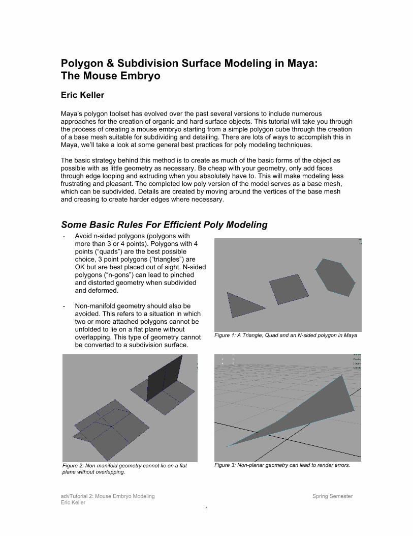
Some Basic Rules For Efficient Poly Modeling - Avoid n-sided polygons (polygons with
more than 3 or 4 points). Polygons with 4 points (“quads”) are the best possible choice, 3 point polygons (“triangles”) are OK but are best placed out of sight. N-sided polygons (“n-gons”) can lead to pinched and distorted geometry when subdivided and deformed.
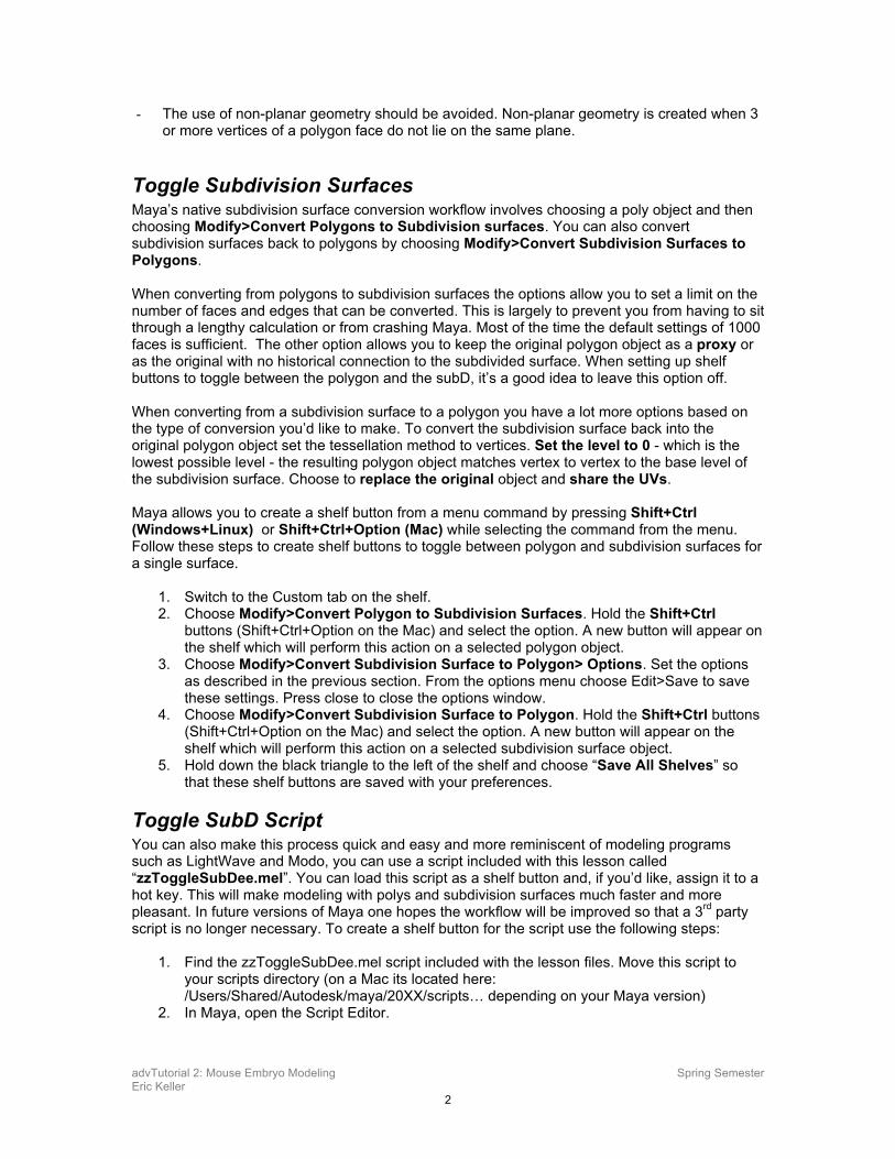
- Non-manifold geometry should also be
avoided. This refers to a situation in which two or more attached polygons cannot be unfolded to lie on a flat plane without overlapping. This type of geometry cannot be converted to a subdivision surface.
Figure 1: A Triangle, Quad and an N-sided polygon in Maya
Figure 2: Non-manifold geometry cannot lie on a flat plane without overlapping.
Figure 3: Non-planar geometry can lead to render errors.
advTutorial 2: Mouse Embryo Modeling Spring Semester Eric Keller
2
- The use of non-planar geometry should be avoided. Non-planar geometry is created when 3 or more vertices of a polygon face do not lie on the same plane.
Toggle Subdivision Surfaces Maya’s native subdivision surface conversion workflow involves choosing a poly object and then choosing Modify>Convert Polygons to Subdivision surfaces. You can also convert subdivision surfaces back to polygons by choosing Modify>Convert Subdivision Surfaces to Polygons. When converting from polygons to subdivision surfaces the options allow you to set a limit on the number of faces and edges that can be converted. This is largely to prevent you from having to sit through a lengthy calculation or from crashing Maya. Most of the time the default settings of 1000 faces is sufficient. The other option allows you to keep the original polygon object as a proxy or as the original with no historical connection to the subdivided surface. When setting up shelf buttons to toggle between the polygon and the subD, it’s a good idea to leave this option off. When converting from a subdivision surface to a polygon you have a lot more options based on the type of conversion you’d like to make. To convert the subdivision surface back into the original polygon object set the tessellation method to vertices. Set the level to 0 - which is the lowest possible level - the resulting polygon object matches vertex to vertex to the base level of the subdivision surface. Choose to replace the original object and share the UVs. Maya allows you to create a shelf button from a menu command by pressing Shift+Ctrl (Windows+Linux) or Shift+Ctrl+Option (Mac) while selecting the command from the menu. Follow these steps to create shelf buttons to toggle between polygon and subdivision surfaces for a single surface.
1. Switch to the Custom tab on the shelf. 2. Choose Modify>Convert Polygon to Subdivision Surfaces. Hold the Shift+Ctrl
buttons (Shift+Ctrl+Option on the Mac) and select the option. A new button will appear on the shelf which will perform this action on a selected polygon object.
3. Choose Modify>Convert Subdivision Surface to Polygon> Options. Set the options as described in the previous section. From the options menu choose Edit>Save to save these settings. Press close to close the options window.
4. Choose Modify>Convert Subdivision Surface to Polygon. Hold the Shift+Ctrl buttons (Shift+Ctrl+Option on the Mac) and select the option. A new button will appear on the shelf which will perform this action on a selected subdivision surface object.
5. Hold down the black triangle to the left of the shelf and choose “Save All Shelves” so that these shelf buttons are saved with your preferences.
Toggle SubD Script You can also make this process quick and easy and more reminiscent of modeling programs such as LightWave and Modo, you can use a script included with this lesson called “zzToggleSubDee.mel”. You can load this script as a shelf button and, if you’d like, assign it to a hot key. This will make modeling with polys and subdivision surfaces much faster and more pleasant. In future versions of Maya one hopes the workflow will be improved so that a 3rd party script is no longer necessary. To create a shelf button for the script use the following steps:
1. Find the zzToggleSubDee.mel script included with the lesson files. Move this script to your scripts directory (on a Mac its located here: /Users/Shared/Autodesk/maya/20XX/scripts… depending on your Maya version)
2. In Maya, open the Script Editor.
advTutorial 2: Mouse Embryo Modeling Spring Semester Eric Keller
3
3. Choose File>Source Script. Use the dialogue to locate the script and source it. The Script is a global procedure, sourcing the script loads it into Maya so that it essentially becomes another command within Maya. Once sourced you can use the command “zzToggleSubDee.mel” in the command line to activate the script. Placing the script in your script directory also ensures that its loaded as a global procedure each time you launch Maya so that you won’t have to source it every time.
4. Create a polygon cube at the origin. 5. In the command line type “zzToggleSubDee;” 6. You should see the cube become a subdivision surface. 7. Open the script editor and look in the history at the top section of the script editor. 8. Select the line that reads “zzToggleSubDee;” 9. Switch the Shelf tabs to “Custom” 10. From the file menu of the script editor choose “save selected to shelf” 11. In the pop up box try and come up with a descriptive name for the shelf button that’s only
6 letters long, its one of the more challenging aspects of working in Maya, much like composing a Haiku. I’ve used “zzSBD”.
12. From the drop down arrow to the left of the shelf, choose “Save all shelves”. 13. Test the button by electing the cube and pressing on the shelf button. The cube should
switch between polygon and subdivision surface mode each time you click the button. 14. You can also use the Hotkey editor to assign the command to your own hotkey
combination. 15. More advanced scripts for this process are available on highend3d.com. Check out
HKSubDConverter.
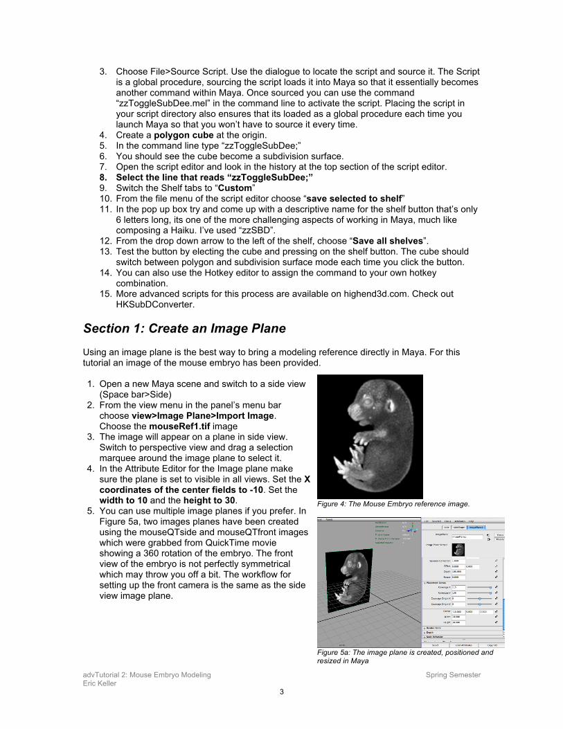
Section 1: Create an Image Plane Using an image plane is the best way to bring a modeling reference directly in Maya. For this tutorial an image of the mouse embryo has been provided. 1. Open a new Maya scene and switch to a side view
(Space bar>Side) 2. From the view menu in the panel’s menu bar
choose view>Image Plane>Import Image. Choose the mouseRef1.tif image
3. The image will appear on a plane in side view. Switch to perspective view and drag a selection marquee around the image plane to select it.
4. In the Attribute Editor for the Image plane make sure the plane is set to visible in all views. Set the X coordinates of the center fields to -10. Set the width to 10 and the height to 30.
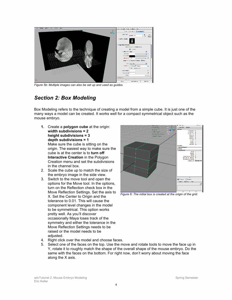
5. You can use multiple image planes if you prefer. In Figure 5a, two images planes have been created using the mouseQTside and mouseQTfront images which were grabbed from QuickTime movie showing a 360 rotation of the embryo. The front view of the embryo is not perfectly symmetrical which may throw you off a bit. The workflow for setting up the front camera is the same as the side view image plane.
Figure 4: The Mouse Embryo reference image.
Figure 5a: The image plane is created, positioned and resized in Maya
advTutorial 2: Mouse Embryo Modeling Spring Semester Eric Keller
4
Figure 5b: Multiple images can also be set up and used as guides.
Section 2: Box Modeling Box Modeling refers to the technique of creating a model from a simple cube. It is just one of the many ways a model can be created. It works well for a compact symmetrical object such as the mouse embryo.
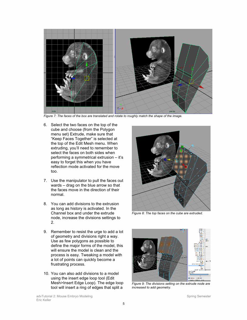
1. Create a polygon cube at the origin: width subdivisions = 2 height subdivisions = 3 depth subdivisions = 1 Make sure the cube is sitting on the origin. The easiest way to make sure the cube is at the center is to turn off Interactive Creation in the Polygon Creation menu and set the subdivisions in the channel box.
2. Scale the cube up to match the size of the embryo image in the side view.
3. Switch to the move tool and open the options for the Move tool. In the options, turn on the Reflection check box in the Move Reflection Settings. Set the axis to X. Set the Center to Origin and the tolerance to 0.01. This will cause the component level changes in the model to be symmetrical. This option works pretty well. As you’ll discover occasionally Maya loses track of the symmetry and either the tolerance in the Move Reflection Settings needs to be raised or the model needs to be adjusted.
4. Right click over the model and choose faces. 5. Select one of the faces on the top. Use the move and rotate tools to move the face up in
Y, rotate it to roughly match the shape of the overall shape of the mouse embryo. Do the same with the faces on the bottom. For right now, don’t worry about moving the face along the X axis.
Figure 6: The initial box is created at the origin of the grid.
advTutorial 2: Mouse Embryo Modeling Spring Semester Eric Keller
5
Figure 7: The faces of the box are translated and rotate to roughly match the shape of the image. 6. Select the two faces on the top of the
cube and choose (from the Polygon menu set) Extrude, make sure that “Keep Faces Together” is selected at the top of the Edit Mesh menu. When extruding, you’ll need to remember to select the faces on both sides when performing a symmetrical extrusion – it’s easy to forget this when you have reflection mode activated for the move too.
7. Use the manipulator to pull the faces out
wards – drag on the blue arrow so that the faces move in the direction of their normal.
8. You can add divisions to the extrusion
as long as history is activated. In the Channel box and under the extrude node, increase the divisions settings to 2.
9. Remember to resist the urge to add a lot
of geometry and divisions right a way. Use as few polygons as possible to define the major forms of the model, this will ensure the model is clean and the process is easy. Tweaking a model with a lot of points can quickly become a frustrating process.
10. You can also add divisions to a model
using the insert edge loop tool (Edit Mesh>Insert Edge Loop). The edge loop tool will insert a ring of edges that split a
Figure 8: The top faces on the cube are extruded.
Figure 9: The divisions setting on the extrude node are increased to add geometry.
advTutorial 2: Mouse Embryo Modeling Spring Semester Eric Keller
6
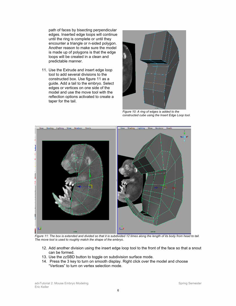
path of faces by bisecting perpendicular edges. Inserted edge loops will continue until the ring is complete or until they encounter a triangle or n-sided polygon. Another reason to make sure the model is made up of polygons is that the edge loops will be created in a clean and predictable manner.
11. Use the Extrude and insert edge loop
tool to add several divisions to the constructed box. Use figure 11 as a guide. Add a tail to the embryo. Select edges or vertices on one side of the model and use the move tool with the reflection options activated to create a taper for the tail.
Figure 11: The box is extended and divided so that it is subdivided 12 times along the length of its body from head to tail. The move tool is used to roughly match the shape of the embryo.
12. Add another division using the insert edge loop tool to the front of the face so that a snout can be formed.
13. Use the zzSBD button to toggle on subdivision surface mode. 14. Press the 3 key to turn on smooth display. Right click over the model and choose
“Vertices” to turn on vertex selection mode.
Figure 10: A ring of edges is added to the constructed cube using the Insert Edge Loop tool.
advTutorial 2: Mouse Embryo Modeling Spring Semester Eric Keller
7
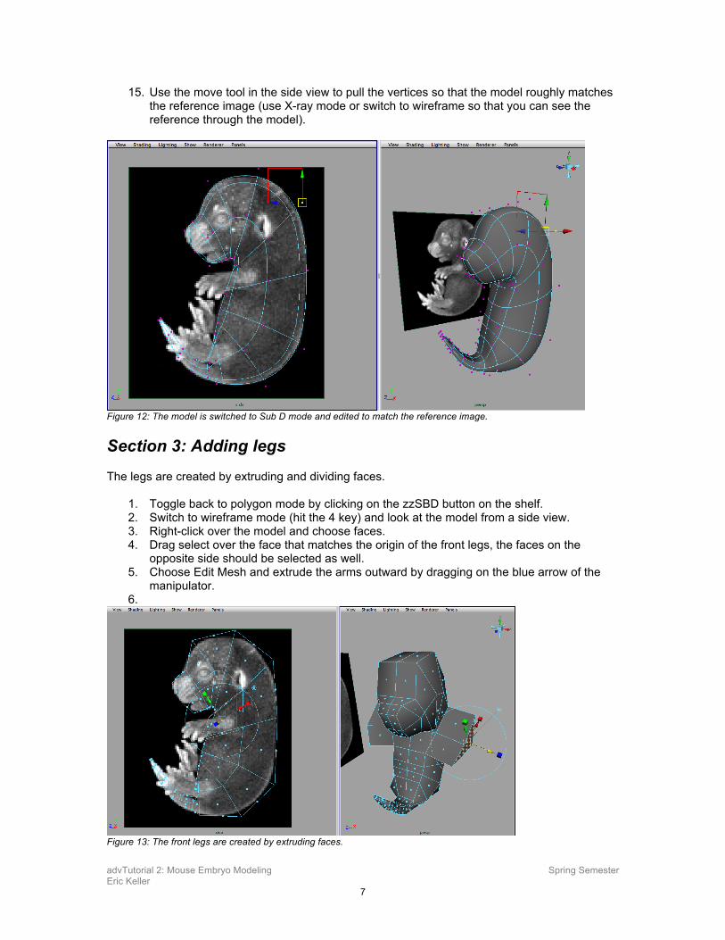
15. Use the move tool in the side view to pull the vertices so that the model roughly matches the reference image (use X-ray mode or switch to wireframe so that you can see the reference through the model).
Figure 12: The model is switched to Sub D mode and edited to match the reference image.
Section 3: Adding legs The legs are created by extruding and dividing faces.
1. Toggle back to polygon mode by clicking on the zzSBD button on the shelf. 2. Switch to wireframe mode (hit the 4 key) and look at the model from a side view. 3. Right-click over the model and choose faces. 4. Drag select over the face that matches the origin of the front legs, the faces on the
opposite side should be selected as well. 5. Choose Edit Mesh and extrude the arms outward by dragging on the blue arrow of the
manipulator. 6.
Figure 13: The front legs are created by extruding faces.
advTutorial 2: Mouse Embryo Modeling Spring Semester Eric Keller
8
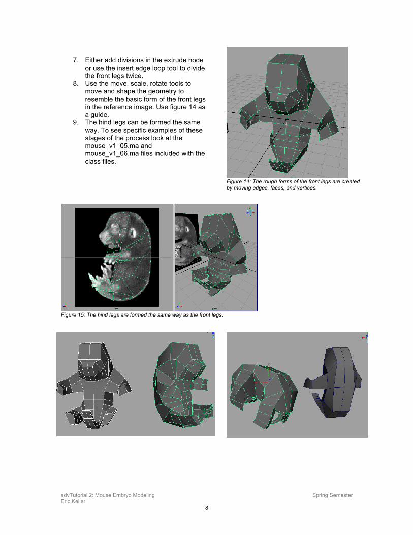
7. Either add divisions in the extrude node
or use the insert edge loop tool to divide the front legs twice.
8. Use the move, scale, rotate tools to move and shape the geometry to resemble the basic form of the front legs in the reference image. Use figure 14 as a guide.
9. The hind legs can be formed the same way. To see specific examples of these stages of the process look at the mouse_v1_05.ma and mouse_v1_06.ma files included with the class files.
Figure 15: The hind legs are formed the same way as the front legs.
Figure 14: The rough forms of the front legs are created by moving edges, faces, and vertices.
advTutorial 2: Mouse Embryo Modeling Spring Semester Eric Keller
9
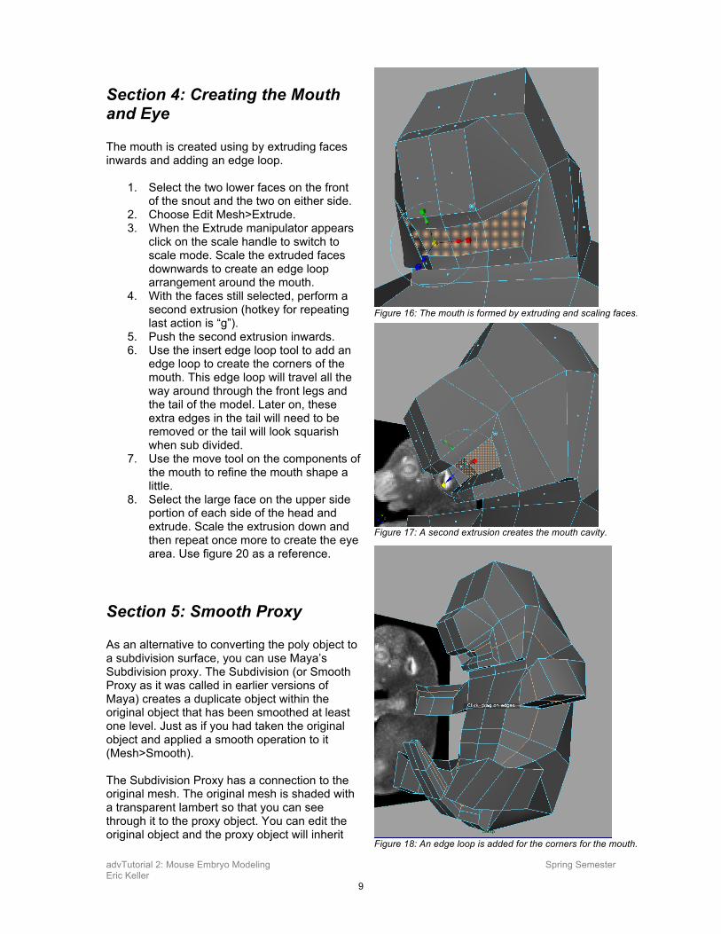
Section 4: Creating the Mouth and Eye The mouth is created using by extruding faces inwards and adding an edge loop.
1. Select the two lower faces on the front of the snout and the two on either side.
2. Choose Edit Mesh>Extrude. 3. When the Extrude manipulator appears
click on the scale handle to switch to scale mode. Scale the extruded faces downwards to create an edge loop arrangement around the mouth.
4. With the faces still selected, perform a second extrusion (hotkey for repeating last action is “g”).
5. Push the second extrusion inwards. 6. Use the insert edge loop tool to add an
edge loop to create the corners of the mouth. This edge loop will travel all the way around through the front legs and the tail of the model. Later on, these extra edges in the tail will need to be removed or the tail will look squarish when sub divided.
7. Use the move tool on the components of the mouth to refine the mouth shape a little.
8. Select the large face on the upper side portion of each side of the head and extrude. Scale the extrusion down and then repeat once more to create the eye area. Use figure 20 as a reference.
Section 5: Smooth Proxy As an alternative to converting the poly object to a subdivision surface, you can use Maya’s Subdivision proxy. The Subdivision (or Smooth Proxy as it was called in earlier versions of Maya) creates a duplicate object within the original object that has been smoothed at least one level. Just as if you had taken the original object and applied a smooth operation to it (Mesh>Smooth). The Subdivision Proxy has a connection to the original mesh. The original mesh is shaded with a transparent lambert so that you can see through it to the proxy object. You can edit the original object and the proxy object will inherit
Figure 16: The mouth is formed by extruding and scaling faces.
Figure 17: A second extrusion creates the mouth cavity.
Figure 18: An edge loop is added for the corners for the mouth.
advTutorial 2: Mouse Embryo Modeling Spring Semester Eric Keller
10
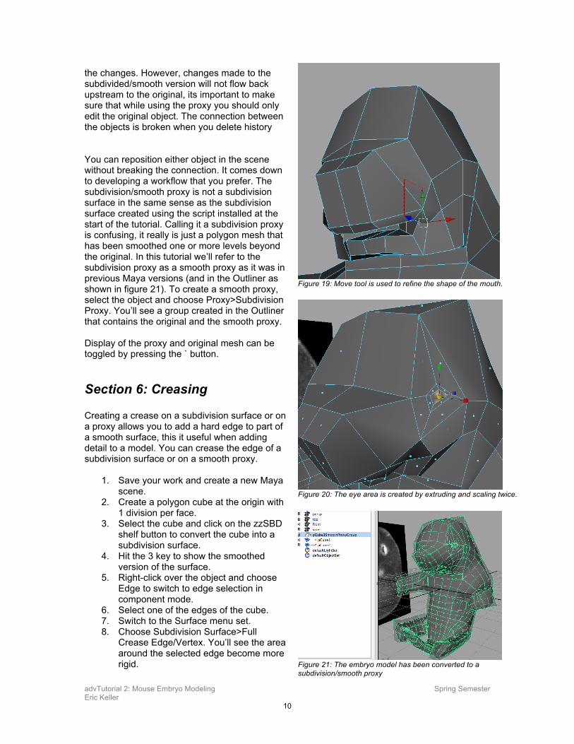
the changes. However, changes made to the subdivided/smooth version will not flow back upstream to the original, its important to make sure that while using the proxy you should only edit the original object. The connection between the objects is broken when you delete history You can reposition either object in the scene without breaking the connection. It comes down to developing a workflow that you prefer. The subdivision/smooth proxy is not a subdivision surface in the same sense as the subdivision surface created using the script installed at the start of the tutorial. Calling it a subdivision proxy is confusing, it really is just a polygon mesh that has been smoothed one or more levels beyond the original. In this tutorial we’ll refer to the subdivision proxy as a smooth proxy as it was in previous Maya versions (and in the Outliner as shown in figure 21). To create a smooth proxy, select the object and choose Proxy>Subdivision Proxy. You’ll see a group created in the Outliner that contains the original and the smooth proxy. Display of the proxy and original mesh can be toggled by pressing the ` button.
Section 6: Creasing Creating a crease on a subdivision surface or on a proxy allows you to add a hard edge to part of a smooth surface, this it useful when adding detail to a model. You can crease the edge of a subdivision surface or on a smooth proxy.
1. Save your work and create a new Maya scene.
2. Create a polygon cube at the origin with 1 division per face.
3. Select the cube and click on the zzSBD shelf button to convert the cube into a subdivision surface.
4. Hit the 3 key to show the smoothed version of the surface.
5. Right-click over the object and choose Edge to switch to edge selection in component mode.
6. Select one of the edges of the cube. 7. Switch to the Surface menu set. 8. Choose Subdivision Surface>Full
Crease Edge/Vertex. You’ll see the area around the selected edge become more rigid.
Figure 19: Move tool is used to refine the shape of the mouth.
Figure 20: The eye area is created by extruding and scaling twice.
Figure 21: The embryo model has been converted to a subdivision/smooth proxy
advTutorial 2: Mouse Embryo Modeling Spring Semester Eric Keller
11
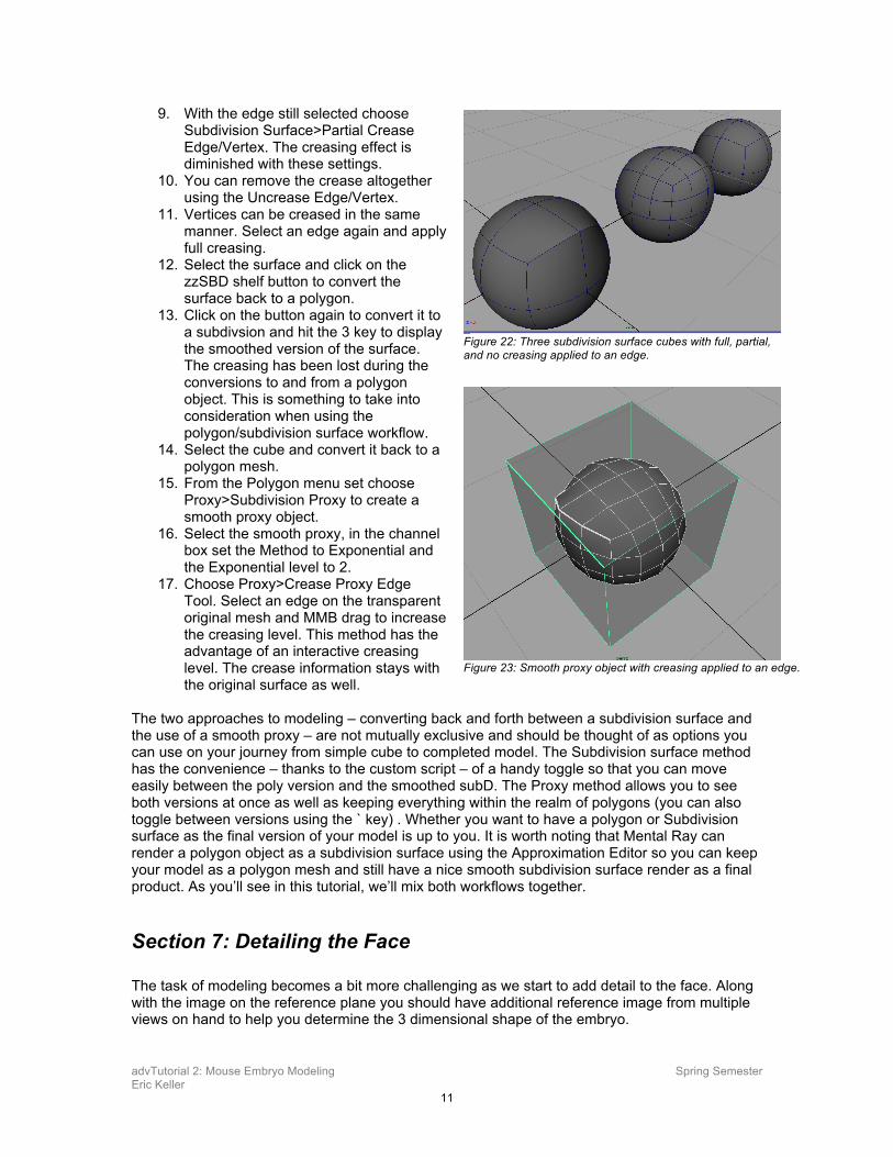
9. With the edge still selected choose Subdivision Surface>Partial Crease Edge/Vertex. The creasing effect is diminished with these settings.
10. You can remove the crease altogether using the Uncrease Edge/Vertex.
11. Vertices can be creased in the same manner. Select an edge again and apply full creasing.
12. Select the surface and click on the zzSBD shelf button to convert the surface back to a polygon.
13. Click on the button again to convert it to a subdivsion and hit the 3 key to display the smoothed version of the surface. The creasing has been lost during the conversions to and from a polygon object. This is something to take into consideration when using the polygon/subdivision surface workflow.
14. Select the cube and convert it back to a polygon mesh.
15. From the Polygon menu set choose Proxy>Subdivision Proxy to create a smooth proxy object.
16. Select the smooth proxy, in the channel box set the Method to Exponential and the Exponential level to 2.
17. Choose Proxy>Crease Proxy Edge Tool. Select an edge on the transparent original mesh and MMB drag to increase the creasing level. This method has the advantage of an interactive creasing level. The crease information stays with the original surface as well.
The two approaches to modeling – converting back and forth between a subdivision surface and the use of a smooth proxy – are not mutually exclusive and should be thought of as options you can use on your journey from simple cube to completed model. The Subdivision surface method has the convenience – thanks to the custom script – of a handy toggle so that you can move easily between the poly version and the smoothed subD. The Proxy method allows you to see both versions at once as well as keeping everything within the realm of polygons (you can also toggle between versions using the ` key) . Whether you want to have a polygon or Subdivision surface as the final version of your model is up to you. It is worth noting that Mental Ray can render a polygon object as a subdivision surface using the Approximation Editor so you can keep your model as a polygon mesh and still have a nice smooth subdivision surface render as a final product. As you’ll see in this tutorial, we’ll mix both workflows together.
Section 7: Detailing the Face The task of modeling becomes a bit more challenging as we start to add detail to the face. Along with the image on the reference plane you should have additional reference image from multiple views on hand to help you determine the 3 dimensional shape of the embryo.
Figure 22: Three subdivision surface cubes with full, partial, and no creasing applied to an edge.
Figure 23: Smooth proxy object with creasing applied to an edge.
advTutorial 2: Mouse Embryo Modeling Spring Semester Eric Keller
12
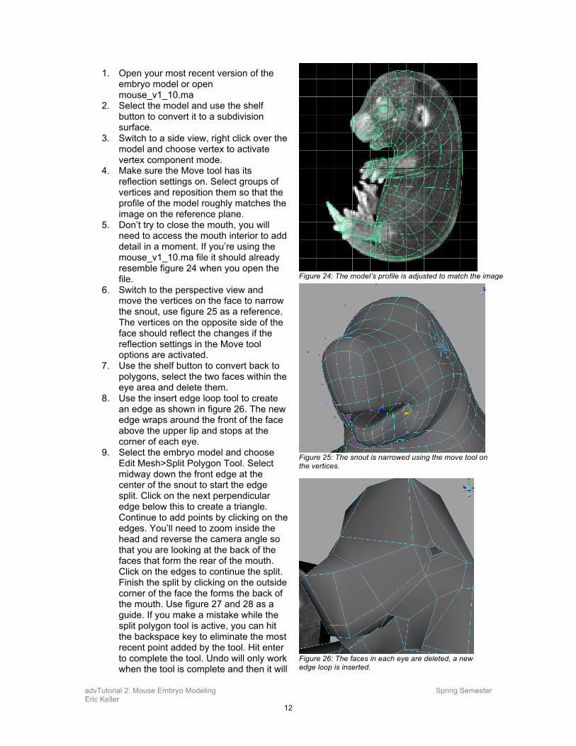
1. Open your most recent version of the embryo model or open mouse_v1_10.ma
2. Select the model and use the shelf button to convert it to a subdivision surface.
3. Switch to a side view, right click over the model and choose vertex to activate vertex component mode.
4. Make sure the Move tool has its reflection settings on. Select groups of vertices and reposition them so that the profile of the model roughly matches the image on the reference plane.
5. Don’t try to close the mouth, you will need to access the mouth interior to add detail in a moment. If you’re using the mouse_v1_10.ma file it should already resemble figure 24 when you open the file.
6. Switch to the perspective view and move the vertices on the face to narrow the snout, use figure 25 as a reference. The vertices on the opposite side of the face should reflect the changes if the reflection settings in the Move tool options are activated.
7. Use the shelf button to convert back to polygons, select the two faces within the eye area and delete them.
8. Use the insert edge loop tool to create an edge as shown in figure 26. The new edge wraps around the front of the face above the upper lip and stops at the corner of each eye.
9. Select the embryo model and choose Edit Mesh>Split Polygon Tool. Select midway down the front edge at the center of the snout to start the edge split. Click on the next perpendicular edge below this to create a triangle. Continue to add points by clicking on the edges. You’ll need to zoom inside the head and reverse the camera angle so that you are looking at the back of the faces that form the rear of the mouth. Click on the edges to continue the split. Finish the split by clicking on the outside corner of the face the forms the back of the mouth. Use figure 27 and 28 as a guide. If you make a mistake while the split polygon tool is active, you can hit the backspace key to eliminate the most recent point added by the tool. Hit enter to complete the tool. Undo will only work when the tool is complete and then it will
Figure 24: The model’s profile is adjusted to match the image
Figure 25: The snout is narrowed using the move tool on the vertices.
Figure 26: The faces in each eye are deleted, a new edge loop is inserted.
advTutorial 2: Mouse Embryo Modeling Spring Semester Eric Keller
13
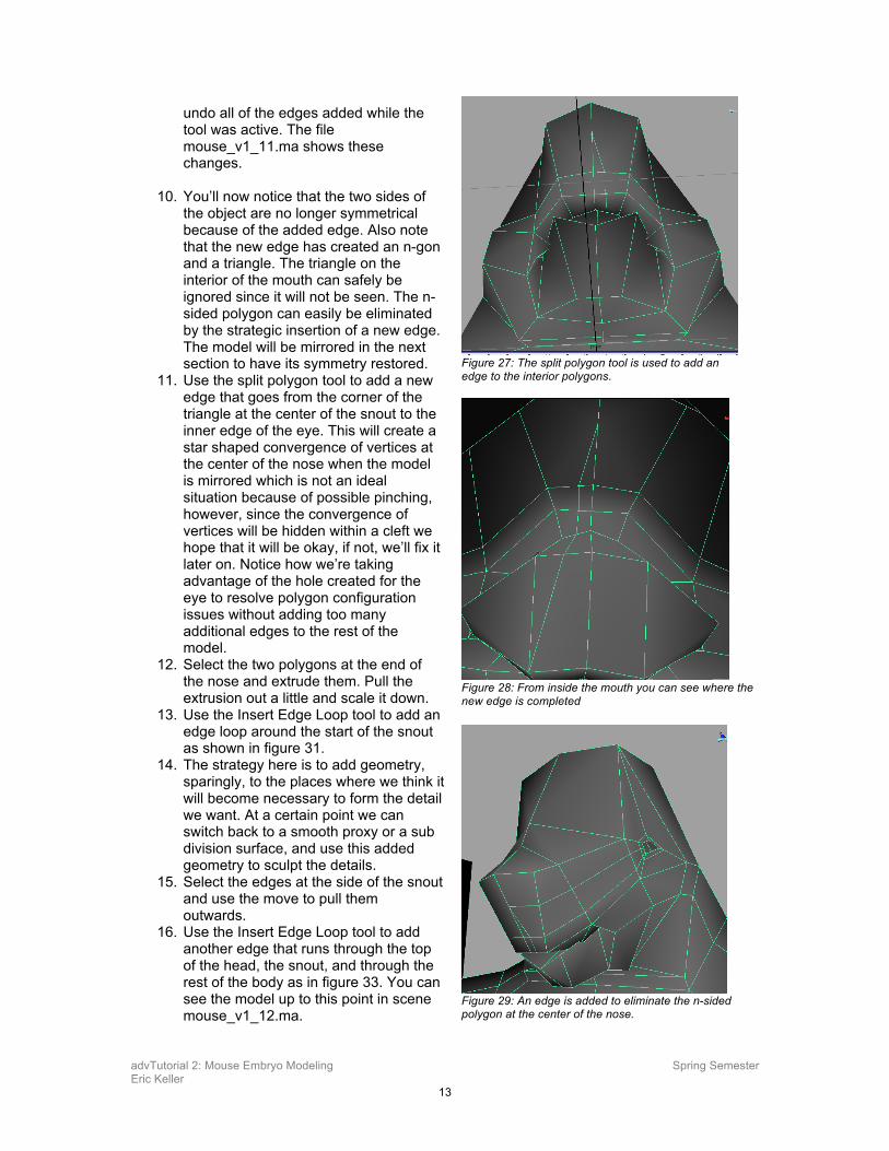
undo all of the edges added while the tool was active. The file mouse_v1_11.ma shows these changes.
10. You’ll now notice that the two sides of
the object are no longer symmetrical because of the added edge. Also note that the new edge has created an n-gon and a triangle. The triangle on the interior of the mouth can safely be ignored since it will not be seen. The n-sided polygon can easily be eliminated by the strategic insertion of a new edge. The model will be mirrored in the next section to have its symmetry restored.
11. Use the split polygon tool to add a new edge that goes from the corner of the triangle at the center of the snout to the inner edge of the eye. This will create a star shaped convergence of vertices at the center of the nose when the model is mirrored which is not an ideal situation because of possible pinching, however, since the convergence of vertices will be hidden within a cleft we hope that it will be okay, if not, we’ll fix it later on. Notice how we’re taking advantage of the hole created for the eye to resolve polygon configuration issues without adding too many additional edges to the rest of the model.
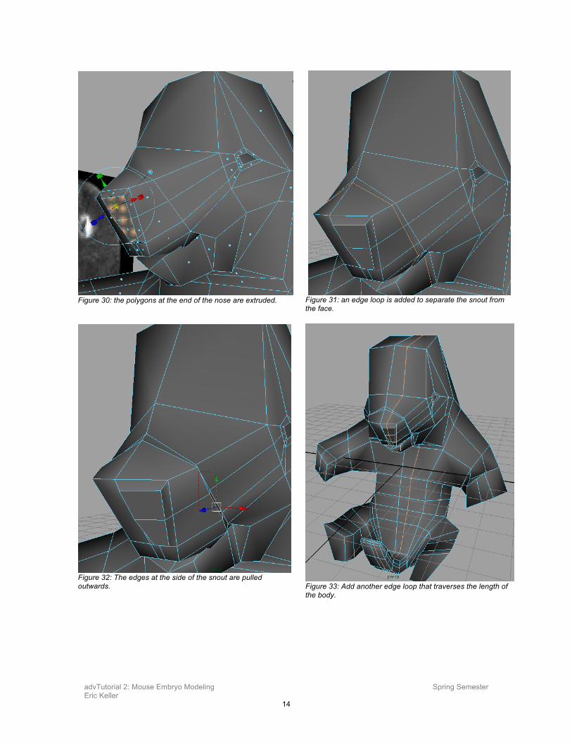
12. Select the two polygons at the end of the nose and extrude them. Pull the extrusion out a little and scale it down.
13. Use the Insert Edge Loop tool to add an edge loop around the start of the snout as shown in figure 31.
14. The strategy here is to add geometry, sparingly, to the places where we think it will become necessary to form the detail we want. At a certain point we can switch back to a smooth proxy or a sub division surface, and use this added geometry to sculpt the details.
15. Select the edges at the side of the snout and use the move to pull them outwards.
16. Use the Insert Edge Loop tool to add another edge that runs through the top of the head, the snout, and through the rest of the body as in figure 33. You can see the model up to this point in scene mouse_v1_12.ma.
Figure 27: The split polygon tool is used to add an edge to the interior polygons.
Figure 28: From inside the mouth you can see where the new edge is completed
Figure 29: An edge is added to eliminate the n-sided polygon at the center of the nose.
advTutorial 2: Mouse Embryo Modeling Spring Semester Eric Keller
14
Figure 30: the polygons at the end of the nose are extruded.
Figure 31: an edge loop is added to separate the snout from the face.
Figure 32: The edges at the side of the snout are pulled outwards.
Figure 33: Add another edge loop that traverses the length of the body.
advTutorial 2: Mouse Embryo Modeling Spring Semester Eric Keller
15
Section 8: Restoring Symmetry To restore symmetry to the model, one half will be deleted - the edited half will be duplicated and merged together.
1. You’ll use the old school method of deletion,
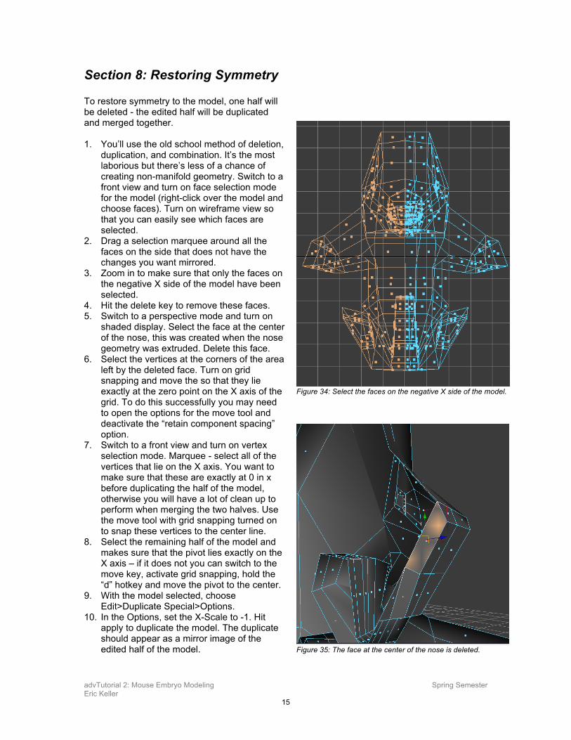
duplication, and combination. It’s the most laborious but there’s less of a chance of creating non-manifold geometry. Switch to a front view and turn on face selection mode for the model (right-click over the model and choose faces). Turn on wireframe view so that you can easily see which faces are selected.
2. Drag a selection marquee around all the faces on the side that does not have the changes you want mirrored.
3. Zoom in to make sure that only the faces on the negative X side of the model have been selected.
4. Hit the delete key to remove these faces. 5. Switch to a perspective mode and turn on
shaded display. Select the face at the center of the nose, this was created when the nose geometry was extruded. Delete this face.
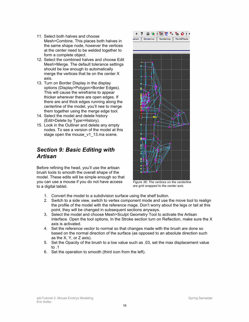
6. Select the vertices at the corners of the area left by the deleted face. Turn on grid snapping and move the so that they lie exactly at the zero point on the X axis of the grid. To do this successfully you may need to open the options for the move tool and deactivate the “retain component spacing” option.
7. Switch to a front view and turn on vertex selection mode. Marquee - select all of the vertices that lie on the X axis. You want to make sure that these are exactly at 0 in x before duplicating the half of the model, otherwise you will have a lot of clean up to perform when merging the two halves. Use the move tool with grid snapping turned on to snap these vertices to the center line.
8. Select the remaining half of the model and makes sure that the pivot lies exactly on the X axis – if it does not you can switch to the move key, activate grid snapping, hold the “d” hotkey and move the pivot to the center.
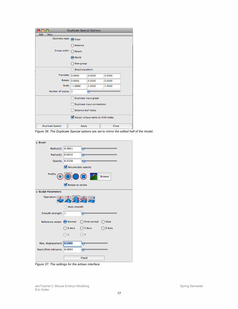
9. With the model selected, choose Edit>Duplicate Special>Options.
10. In the Options, set the X-Scale to -1. Hit apply to duplicate the model. The duplicate should appear as a mirror image of the edited half of the model.
Figure 34: Select the faces on the negative X side of the model.
Figure 35: The face at the center of the nose is deleted.
advTutorial 2: Mouse Embryo Modeling Spring Semester Eric Keller
16
11. Select both halves and choose
Mesh>Combine. This places both halves in the same shape node, however the vertices at the center need to be welded together to form a complete object.
12. Select the combined halves and choose Edit Mesh>Merge. The default tolerance settings should be low enough to automatically merge the vertices that lie on the center X axis.
13. Turn on Border Display in the display options (Display>Polygon>Border Edges). This will cause the wireframe to appear thicker wherever there are open edges. If there are and thick edges running along the centerline of the model, you’ll nee to merge them together using the merge edge tool.
14. Select the model and delete history (Edit>Delete by Type>History).
15. Look in the Outliner and delete any empty nodes. To see a version of the model at this stage open the mouse_v1_13.ma scene.
Section 9: Basic Editing with Artisan Before refining the head, you’ll use the artisan brush tools to smooth the overall shape of the model. These edits will be simple enough so that you can use a mouse if you do not have access to a digital tablet.
1. Convert the model to a subdivision surface using the shelf button. 2. Switch to a side view, switch to vertex component mode and use the move tool to realign
the profile of the model with the reference mage. Don’t worry about the legs or tail at this point, they will be changed in subsequent sections anyways.
3. Select the model and choose Mesh>Sculpt Geometry Tool to activate the Artisan interface. Open the tool options, In the Stroke section turn on Reflection, make sure the X axis is activated.
4. Set the reference vector to normal so that changes made with the brush are done so based on the normal direction of the surface (as opposed to an absolute direction such as the X, Y, or Z axis).
5. Set the Opacity of the brush to a low value such as .03, set the max displacement value to .1
6. Set the operation to smooth (third icon from the left).
Figure 36: The vertices on the centerline are grid snapped to the center axis.
advTutorial 2: Mouse Embryo Modeling Spring Semester Eric Keller
17
Figure 36: The Duplicate Special options are set to mirror the edited half of the model.
Figure 37: The settings for the artisan interface
advTutorial 2: Mouse Embryo Modeling Spring Semester Eric Keller
18
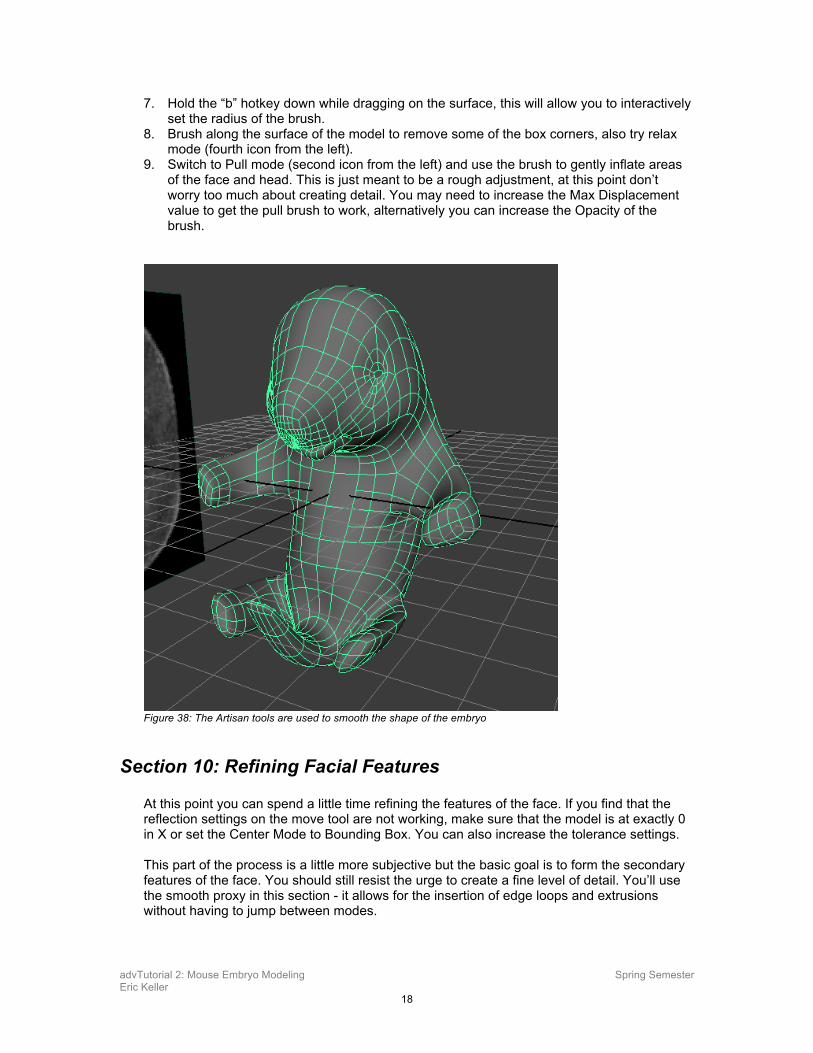
7. Hold the “b” hotkey down while dragging on the surface, this will allow you to interactively set the radius of the brush.
8. Brush along the surface of the model to remove some of the box corners, also try relax mode (fourth icon from the left).
9. Switch to Pull mode (second icon from the left) and use the brush to gently inflate areas of the face and head. This is just meant to be a rough adjustment, at this point don’t worry too much about creating detail. You may need to increase the Max Displacement value to get the pull brush to work, alternatively you can increase the Opacity of the brush.
Figure 38: The Artisan tools are used to smooth the shape of the embryo
Section 10: Refining Facial Features At this point you can spend a little time refining the features of the face. If you find that the reflection settings on the move tool are not working, make sure that the model is at exactly 0 in X or set the Center Mode to Bounding Box. You can also increase the tolerance settings. This part of the process is a little more subjective but the basic goal is to form the secondary features of the face. You should still resist the urge to create a fine level of detail. You’ll use the smooth proxy in this section - it allows for the insertion of edge loops and extrusions without having to jump between modes.
advTutorial 2: Mouse Embryo Modeling Spring Semester Eric Keller
19
1. Convert the model back to a polygon mode, to create a smooth proxy, select the model and choose Proxy> Subdiv Proxy.
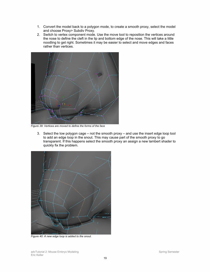
2. Switch to vertex component mode. Use the move tool to reposition the vertices around the nose to define the cleft in the lip and bottom edge of the nose. This will take a little noodling to get right. Sometimes it may be easier to select and move edges and faces rather than vertices.
Figure 39: Vertices are moved to define the forms of the face
3. Select the low polygon cage – not the smooth proxy – and use the insert edge loop tool to add an edge loop in the snout. This may cause part of the smooth proxy to go transparent. If this happens select the smooth proxy an assign a new lambert shader to quickly fix the problem.
Figure 40: A new edge loop is added to the snout.
advTutorial 2: Mouse Embryo Modeling Spring Semester Eric Keller
20
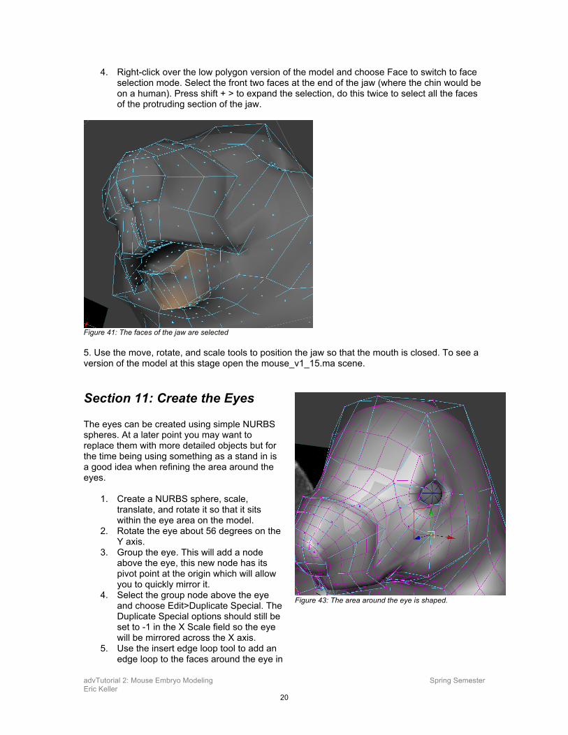
4. Right-click over the low polygon version of the model and choose Face to switch to face selection mode. Select the front two faces at the end of the jaw (where the chin would be on a human). Press shift + > to expand the selection, do this twice to select all the faces of the protruding section of the jaw.
Figure 41: The faces of the jaw are selected 5. Use the move, rotate, and scale tools to position the jaw so that the mouth is closed. To see a version of the model at this stage open the mouse_v1_15.ma scene.
Section 11: Create the Eyes The eyes can be created using simple NURBS spheres. At a later point you may want to replace them with more detailed objects but for the time being using something as a stand in is a good idea when refining the area around the eyes.
1. Create a NURBS sphere, scale, translate, and rotate it so that it sits within the eye area on the model.
2. Rotate the eye about 56 degrees on the Y axis.
3. Group the eye. This will add a node above the eye, this new node has its pivot point at the origin which will allow you to quickly mirror it.
4. Select the group node above the eye and choose Edit>Duplicate Special. The Duplicate Special options should still be set to -1 in the X Scale field so the eye will be mirrored across the X axis.
5. Use the insert edge loop tool to add an edge loop to the faces around the eye in
Figure 43: The area around the eye is shaped.
advTutorial 2: Mouse Embryo Modeling Spring Semester Eric Keller
21
the low polygon version of the model. This edge loop will not be mirrored to the opposite side but that OK, you’ll have to repeat the mirroring process anyway after you create the toes.
6. Spend some time refining the area around the eyes using the move tool on the vertices of the low polygon version of the model. You may want to turn on wireframe on shaded in the shading options of the panel so that the topology of the smooth proxy is easier to see. You can also select the smooth proxy and apply a blinn texture, the specular highlight in the openGL preview can help you to see the forms a little better. Don’t add any new geometry using edge loops or extrusions at this point, work with what you have in the model as best you can. mouse_v1_16.ma scene.
Section 12: Create the Toes You can leave the head for the moment and move on to creating the toes.
1. Spend a few moments selecting and moving the edges that define the front leg, you don’t need to perfect it, just round it out a little before adding geometry.
2. Insert an edge loop that splits the arm in half, this edge loop will run across the chest and through the opposite arm.
3. Insert a second edge loop that runs around the end of the foot.
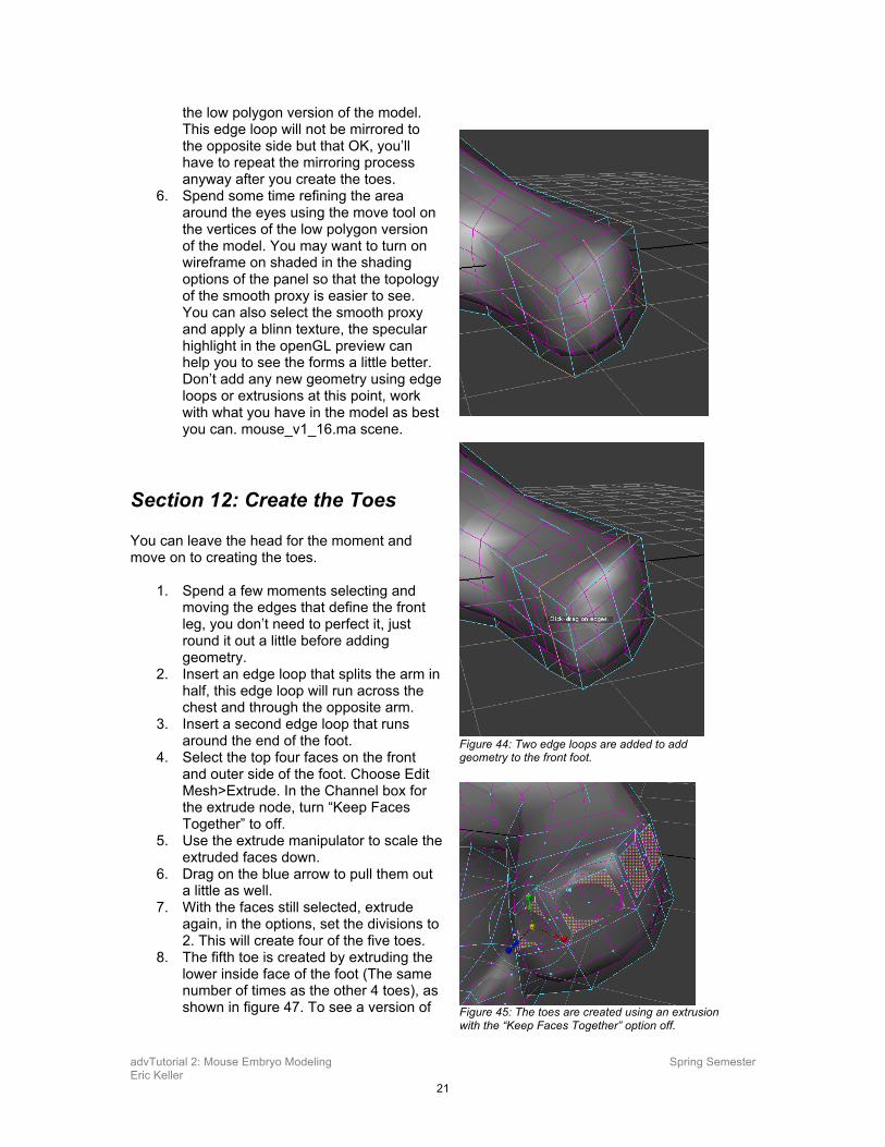
4. Select the top four faces on the front and outer side of the foot. Choose Edit Mesh>Extrude. In the Channel box for the extrude node, turn “Keep Faces Together” to off.
5. Use the extrude manipulator to scale the extruded faces down.
6. Drag on the blue arrow to pull them out a little as well.
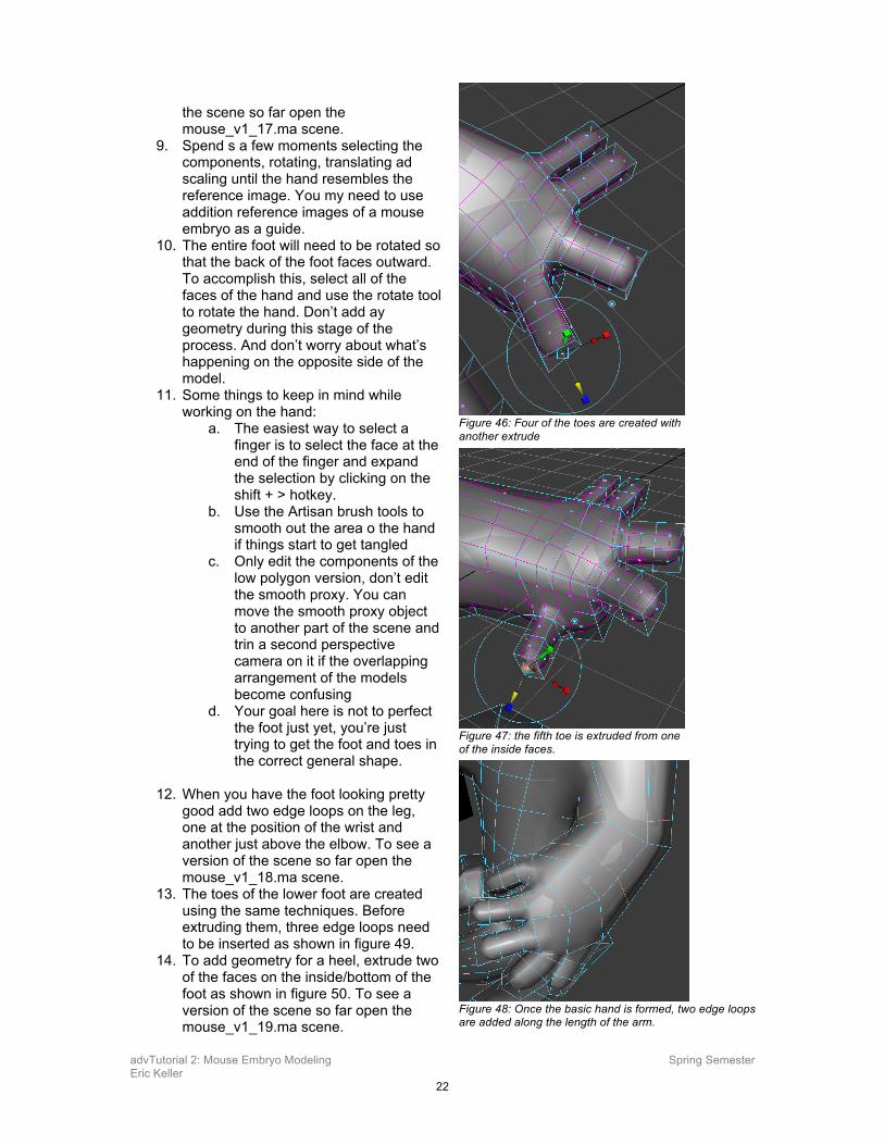
7. With the faces still selected, extrude again, in the options, set the divisions to 2. This will create four of the five toes.
8. The fifth toe is created by extruding the lower inside face of the foot (The same number of times as the other 4 toes), as shown in figure 47. To see a version of
Figure 44: Two edge loops are added to add geometry to the front foot.
Figure 45: The toes are created using an extrusion with the “Keep Faces Together” option off.
advTutorial 2: Mouse Embryo Modeling Spring Semester Eric Keller
22
the scene so far open the mouse_v1_17.ma scene.
9. Spend s a few moments selecting the components, rotating, translating ad scaling until the hand resembles the reference image. You my need to use addition reference images of a mouse embryo as a guide.
10. The entire foot will need to be rotated so that the back of the foot faces outward. To accomplish this, select all of the faces of the hand and use the rotate tool to rotate the hand. Don’t add ay geometry during this stage of the process. And don’t worry about what’s happening on the opposite side of the model.
11. Some things to keep in mind while working on the hand:
a. The easiest way to select a finger is to select the face at the end of the finger and expand the selection by clicking on the shift + > hotkey.
b. Use the Artisan brush tools to smooth out the area o the hand if things start to get tangled
c. Only edit the components of the low polygon version, don’t edit the smooth proxy. You can move the smooth proxy object to another part of the scene and trin a second perspective camera on it if the overlapping arrangement of the models become confusing
d. Your goal here is not to perfect the foot just yet, you’re just trying to get the foot and toes in the correct general shape.
12. When you have the foot looking pretty
good add two edge loops on the leg, one at the position of the wrist and another just above the elbow. To see a version of the scene so far open the mouse_v1_18.ma scene.
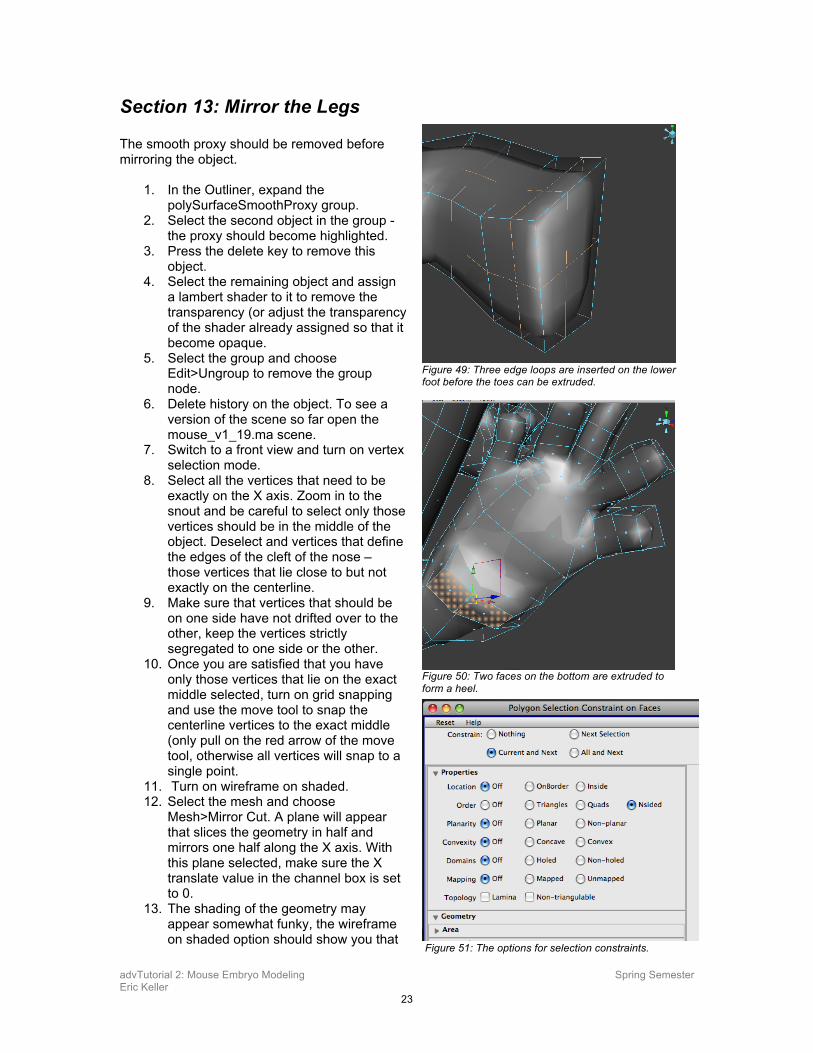
13. The toes of the lower foot are created using the same techniques. Before extruding them, three edge loops need to be inserted as shown in figure 49.
14. To add geometry for a heel, extrude two of the faces on the inside/bottom of the foot as shown in figure 50. To see a version of the scene so far open the mouse_v1_19.ma scene.
Figure 46: Four of the toes are created with another extrude
Figure 47: the fifth toe is extruded from one of the inside faces.
Figure 48: Once the basic hand is formed, two edge loops are added along the length of the arm.
advTutorial 2: Mouse Embryo Modeling Spring Semester Eric Keller
23
Section 13: Mirror the Legs The smooth proxy should be removed before mirroring the object.
1. In the Outliner, expand the polySurfaceSmoothProxy group.
2. Select the second object in the group - the proxy should become highlighted.
3. Press the delete key to remove this object.
4. Select the remaining object and assign a lambert shader to it to remove the transparency (or adjust the transparency of the shader already assigned so that it become opaque.
5. Select the group and choose Edit>Ungroup to remove the group node.
6. Delete history on the object. To see a version of the scene so far open the mouse_v1_19.ma scene.
7. Switch to a front view and turn on vertex selection mode.
8. Select all the vertices that need to be exactly on the X axis. Zoom in to the snout and be careful to select only those vertices should be in the middle of the object. Deselect and vertices that define the edges of the cleft of the nose – those vertices that lie close to but not exactly on the centerline.
9. Make sure that vertices that should be on one side have not drifted over to the other, keep the vertices strictly segregated to one side or the other.
10. Once you are satisfied that you have only those vertices that lie on the exact middle selected, turn on grid snapping and use the move tool to snap the centerline vertices to the exact middle (only pull on the red arrow of the move tool, otherwise all vertices will snap to a single point.
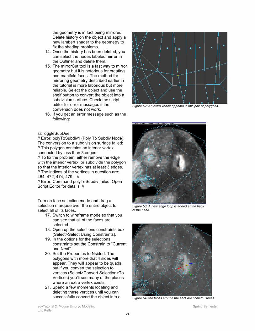
11. Turn on wireframe on shaded. 12. Select the mesh and choose
Mesh>Mirror Cut. A plane will appear that slices the geometry in half and mirrors one half along the X axis. With this plane selected, make sure the X translate value in the channel box is set to 0.
13. The shading of the geometry may appear somewhat funky, the wireframe on shaded option should show you that
Figure 49: Three edge loops are inserted on the lower foot before the toes can be extruded.
Figure 50: Two faces on the bottom are extruded to form a heel.
Figure 51: The options for selection constraints.
advTutorial 2: Mouse Embryo Modeling Spring Semester Eric Keller
24
the geometry is in fact being mirrored. Delete history on the object and apply a new lambert shader to the geometry to fix the shading problems.
14. Once the history has been deleted, you can select the nodes labeled mirror in the Outliner and delete them.
15. The mirrorCut tool is a fast way to mirror geometry but it is notorious for creating non manifold faces. The method for mirroring geometry described earlier in the tutorial is more laborious but more reliable. Select the object and use the shelf button to convert the object into a subdvision surface. Check the script editor for error messages if the conversion does not work.
16. If you get an error message such as the following:
zzToggleSubDee; // Error: polyToSubdiv1 (Poly To Subdiv Node): The conversion to a subdivision surface failed: // This polygon contains an interior vertex connected by less than 3 edges. // To fix the problem, either remove the edge with the interior vertex, or subdivide the polygon so that the interior vertex has at least 3 edges. // The indices of the vertices in question are: 464, 472, 474, 479. // // Error: Command polyToSubdiv failed. Open Script Editor for details. // Turn on face selection mode and drag a selection marquee over the entire object to select all of its faces.
17. Switch to wireframe mode so that you can see that all of the faces are selected.
18. Open up the selections constraints box (Select>Select Using Constraints).
19. In the options for the selections constraints set the Constrain to “Current and Next”.
20. Set the Properties to Nsided. The polygons with more that 4 sides will appear. They will appear to be quads but if you convert the selection to vertices (Select>Convert Selection>To Vertices) you’ll see many of the places where an extra vertex exists.
21. Spend a few moments locating and deleting these vertices until you can successfully convert the object into a
Figure 53: A new edge loop is added at the back of the head.
Figure 54: the faces around the ears are scaled 3 times.
Figure 52: An extra vertex appears in this pair of polygons.
advTutorial 2: Mouse Embryo Modeling Spring Semester Eric Keller
25
polygon. Now that you see the pitfalls of using automated mirroring processes in Maya you’ll probably want to go back to using the old school method of delete, duplicated, and combine for mirroring the object.
22. Once you have the model successfully mirrored convert it back to polygons and save it. To see a version of the scene so far open the mouse_v1_20.ma scene.
Section 14: Finishing the Head Only a few more details need to be added to finish the head before the base geometry is complete.
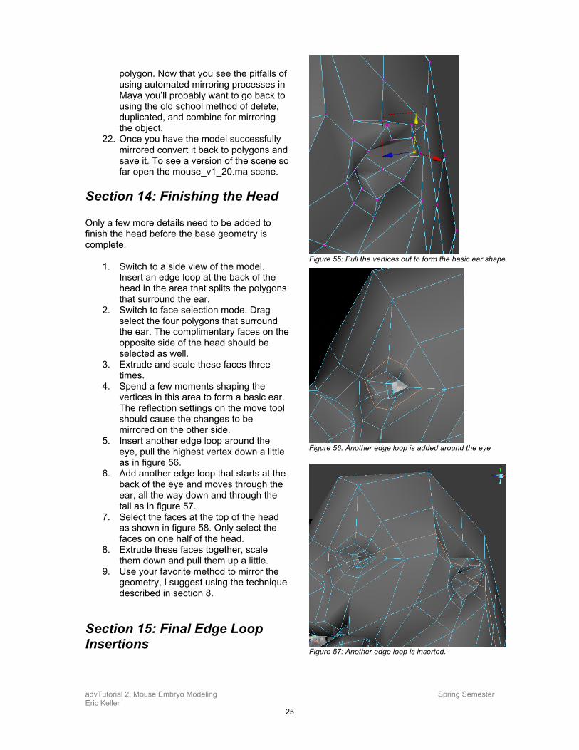
1. Switch to a side view of the model. Insert an edge loop at the back of the head in the area that splits the polygons that surround the ear.
2. Switch to face selection mode. Drag select the four polygons that surround the ear. The complimentary faces on the opposite side of the head should be selected as well.
3. Extrude and scale these faces three times.
4. Spend a few moments shaping the vertices in this area to form a basic ear. The reflection settings on the move tool should cause the changes to be mirrored on the other side.
5. Insert another edge loop around the eye, pull the highest vertex down a little as in figure 56.
6. Add another edge loop that starts at the back of the eye and moves through the ear, all the way down and through the tail as in figure 57.
7. Select the faces at the top of the head as shown in figure 58. Only select the faces on one half of the head.
8. Extrude these faces together, scale them down and pull them up a little.
9. Use your favorite method to mirror the geometry, I suggest using the technique described in section 8.
Section 15: Final Edge Loop Insertions
Figure 55: Pull the vertices out to form the basic ear shape.
Figure 56: Another edge loop is added around the eye
Figure 57: Another edge loop is inserted.
advTutorial 2: Mouse Embryo Modeling Spring Semester Eric Keller
26
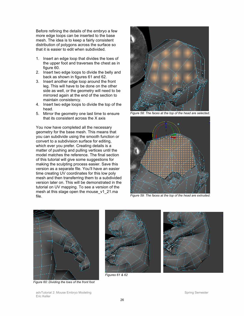
Before refining the details of the embryo a few more edge loops can be inserted to the base mesh. The idea is to keep a fairly consistent distribution of polygons across the surface so that it is easier to edit when subdivided. 1. Insert an edge loop that divides the toes of
the upper foot and traverses the chest as in figure 60.
2. Insert two edge loops to divide the belly and back as shown in figures 61 and 62.
3. Insert another edge loop around the front leg. This will have to be done on the other side as well, or the geometry will need to be mirrored again at the end of the section to maintain consistency.
4. Insert two edge loops to divide the top of the head.
5. Mirror the geometry one last time to ensure that its consistent across the X axis
You now have completed all the necessary geometry for the base mesh. This means that you can subdivide using the smooth function or convert to a subdivision surface for editing, which ever you prefer. Creating details is a matter of pushing and pulling vertices until the model matches the reference. The final section of this tutorial will give some suggestions for making the sculpting process easier. Save this version as a separate file. You’ll have an easier time creating UV coordinates for this low poly mesh and then transferring them to a subdivided version later on. This will be demonstrated in the tutorial on UV mapping. To see a version of the mesh at this stage open the mouse_v1_21.ma file.
Figure 58: The faces at the top of the head are selected.
Figure 59: The faces at the top of the head are extruded.
Figure 60: Dividing the toes of the front foot
Figures 61 & 62
advTutorial 2: Mouse Embryo Modeling Spring Semester Eric Keller
27
Refining the Model There are a number of ways you can bring the base mesh to the point of a detailed model. Ultimately each way will rely on a great deal of time carefully manipulating the surface by translating, rotating, and scaling vertices, edges, and faces. This section will provide you with some advice on the different approaches you can take.
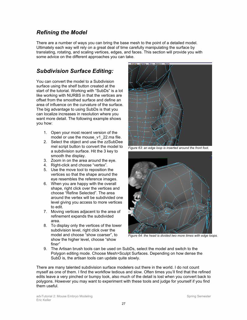
Subdivision Surface Editing: You can convert the model to a Subdivision surface using the shelf button created at the start of the tutorial. Working with “SubDs” is a lot like working with NURBS in that the vertices are offset from the smoothed surface and define an area of influence on the curvature of the surface. The big advantage to using SubDs is that you can localize increases in resolution where you want more detail. The following example shows you how:
1. Open your most recent version of the model or use the mouse_v1_22.ma file.
2. Select the object and use the zzSubDee mel script button to convert the model to a subdivision surface. Hit the 3 key to smooth the display.
3. Zoom in on the area around the eye. 4. Right-click and choose “vertex”. 5. Use the move tool to reposition the
vertices so that the shape around the eye resembles the reference images.
6. When you are happy with the overall shape, right click over the vertices and choose “Refine Selected”. The area around the vertex will be subdivided one level giving you access to more vertices to edit.
7. Moving vertices adjacent to the area of refinement expands the subdivided area.
8. To display only the vertices of the lower subdivision level, right click over the model and choose “show coarser”, to show the higher level, choose “show finer”
9. The Artisan brush tools can be used on SubDs, select the model and switch to the Polygon editing mode. Choose Mesh>Sculpt Surfaces. Depending on how dense the SubD is, the artisan tools can update quite slowly.
There are many talented subdivision surface modelers out there in the world. I do not count myself as one of them. I find the workflow tedious and slow. Often times you’ll find that the refined edits leave a very pinched or bumpy look, also much of the detail is lost when you convert back to polygons. However you may want to experiment with these tools and judge for yourself if you find them useful.
Figure 63: an edge loop is inserted around the front foot.
Figure 64: the head is divided two more times with edge loops.
advTutorial 2: Mouse Embryo Modeling Spring Semester Eric Keller
28
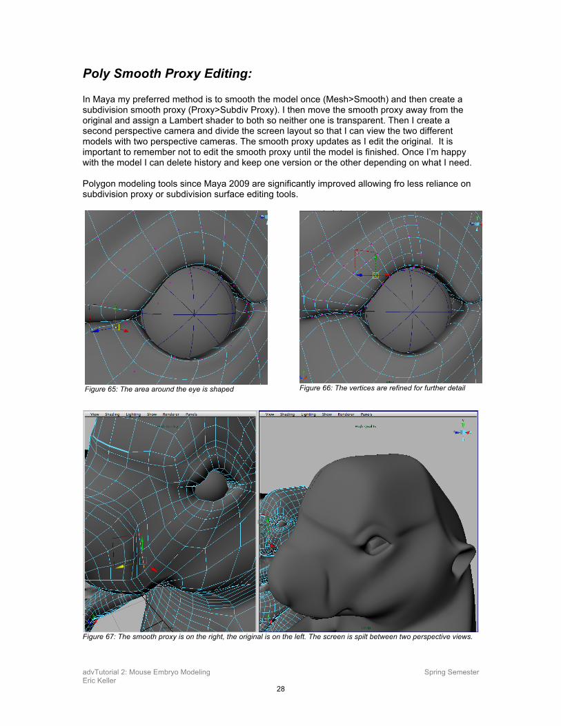
Poly Smooth Proxy Editing: In Maya my preferred method is to smooth the model once (Mesh>Smooth) and then create a subdivision smooth proxy (Proxy>Subdiv Proxy). I then move the smooth proxy away from the original and assign a Lambert shader to both so neither one is transparent. Then I create a second perspective camera and divide the screen layout so that I can view the two different models with two perspective cameras. The smooth proxy updates as I edit the original. It is important to remember not to edit the smooth proxy until the model is finished. Once I’m happy with the model I can delete history and keep one version or the other depending on what I need. Polygon modeling tools since Maya 2009 are significantly improved allowing fro less reliance on subdivision proxy or subdivision surface editing tools.
Figure 67: The smooth proxy is on the right, the original is on the left. The screen is spilt between two perspective views.
Figure 65: The area around the eye is shaped
Figure 66: The vertices are refined for further detail
advTutorial 2: Mouse Embryo Modeling Spring Semester Eric Keller
29
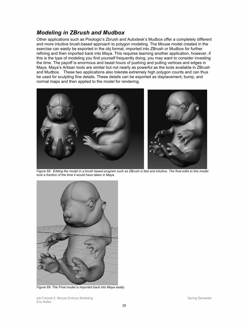
Modeling in ZBrush and Mudbox Other applications such as Pixologic’s Zbrush and Autodesk’s Mudbox offer a completely different and more intuitive brush-based approach to polygon modeling. The Mouse model created in the exercise can easily be exported in the obj format, imported into ZBrush or Mudbox for further refining and then imported back into Maya. This requires learning another application, however, if this is the type of modeling you find yourself frequently doing, you may want to consider investing the time. The payoff is enormous and beast hours of pushing and pulling vertices and edges in Maya. Maya’s Artisan tools are similar but not nearly as powerful as the tools available in ZBrush and Mudbox. These two applications also tolerate extremely high polygon counts and can thus be used for sculpting fine details. These details can be exported as displacement, bump, and normal maps and then applied to the model for rendering.
Figure 68: Editing the model in a brush based program such as ZBrush is fast and intuitive. The final edits to this model took a fraction of the time it would have taken in Maya.
Figure 69: The Final model is imported back into Maya easily.