Embed Size (px)
Citation preview
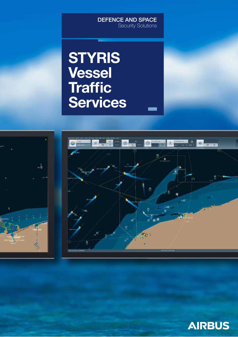
STYRIS Vessel Traffic Services
DEFENCE AND SPACESecurity Solutions
Modularity & ScalabilityIntegrated but modular systems with the potential to be enlarged - Increasing the size without losing investments Port facilities, infrastructures and VTS monitoring areas are continually expanding and developing inline with the fast moving maritime business. Our VTS Systems have been designed to grow with your requirements. At any time additional sensors, functions or external data communication channels may be added to the System without interruption or loss of existing subsystems. Additional software features can be integrated into the STYRIS® VTS Systems on demand to match the growing needs of the dynamic VTS and Port businesses.
Stability & ReliabilityHigh stability and reliability through high quality componentsVTS Systems are safety-critical applications, so it is essential that System operation is never compromised by performance, availability or precision. System stability and reliability have thus been pursued as two primary design goals for STYRIS® product family. Consequently STYRIS® VTS Systems incorporate the technical means to ensure highest System availability, best MTBF and minimal MTTR. Airbus is an ISO 9001 certified company and should be your first choice when total 24/7 VTS operations are your business.
User Centred DesignApplying a Scientific approach to HMI designUser- centered design principles were applied to identify the most commonly used functions in a VTS center before focusing on them by optimizing their access both visually and from an interaction point of view.
Customer OrientationTailor made solution according customers’ needsPorts and harbours, inland waterways and coastal waters have their distinct environments, individual infrastructures and thus different requirements. To meet such wide – ranging requirements STYRIS® VTS product is designed to be highly configurable and adaptable to any degree of complexity. From local VTS solutions with only a few radars and sensors to integrated VTS networks providing surveillance at regional or even at national level with a large number of different monitoring sensors Airbus delivers your VTS solution.
STYRIS® VTS Systems not only provide IALA compliant Information (INS), Navigational Assistance (NAS) and Traffic Organization Services (TOS), but deliver a much wider scope of value - added services to ships, harbours and other commercial port services.
STYRIS® VTS belongs to the third generation of the Airbus in-house Maritime Security product family, application dedicated to standard VTS solutions with options (add-ons).
STYRIS® VTS is built on the following design principles, which make it so unique:
STYRIS® HMI has been developed according to the main following principles:
Minimizing mouse movements and clicksRelated functions have been grouped into user interaction are as for quick and intuitive access to obtain higher efficiency and reduced mental load.
Control room centric designVTS-specific ergonomic aspects have been taken into consideration. For example, average viewing distance and frequent workflow interruptions are typical constraints that directly translate on the choice for appropriate fonts, icon size or mode less interactions.
Dark cockpit principleOnly relevant information or settings deviating from standards are shown, thus applying the new IALA recommendations for portrayal of VTS data.
Instant search toolIn addition to regular menus and dialog boxes, the idea is to provide an alternative way of accessing functions through an interactive search tool. This allows operators working with different VTS systems to leverage their existing operational expertise.
Besides the redesign of the HMI, our developers have concentrated in the renovation of key functions such as Camera & Video management, Record & Replay and Alerts and Events management (based on a Rules Engine).
Cost effectivenessSolutions based on COTS Hardware with low maintenance costs.
HMI LayoutThe new STYRIS® HMI has been built on Airbus strong experience in delivering Coastal and Port VTS solutions worldwide and on the feedbacks gathered from VTS operators during training sessions and at user conferences.STYRIS® HMI design was developed within the HMI team lead by an ergonomic expert to achieve the best ergonomic HMI for VTS Operator’s tasks in order to:• Maintain awareness of the complete traffic
image generated from fused data of the sensors,
• Provide intuitive means for the VTS operator to retrieve detailed information related to the objects displayed on the traffic image,
• Provide intuitive means for the VTS operator to interact with the VTS functions (sensor settings, Cameras control).
Let’s experience and navigate with STYRIS® VTS …
In the following pages, STYRIS® VTS is described focusing on system functions, important operational details and vessel traffic image features.
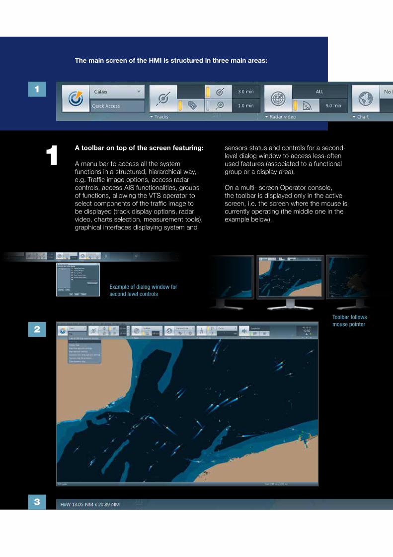
2
1
3
sensors status and controls for a second-level dialog window to access less-often used features (associated to a functional group or a display area).
On a multi- screen Operator console, the toolbar is displayed only in the active screen, i.e. the screen where the mouse is currently operating (the middle one in the example below).
A toolbar on top of the screen featuring:
A menu bar to access all the system functions in a structured, hierarchical way, e.g. Traffic image options, access radar controls, access AIS functionalities, groups of functions, allowing the VTS operator to select components of the traffic image to be displayed (track display options, radar video, charts selection, measurement tools), graphical interfaces displaying system and
1
The main screen of the HMI is structured in three main areas:
Example of dialog window for second level controls
Toolbar follows mouse pointer

3 A status bar at the bottom of the screen, used to display parameter values associatedto the viewport and the cursor position:
• Chart: Selection of the appropriate Chart profile for the current task
• Operator tools: Distance & bearing measurement CPAs and ETAs calculation tools Direction Finder bearing
• Automated Events detection: Zones where Automated Events detection is available
A main window, where the Traffic Image and some graphical operator’s tools are displayed.
• Radar video: Radar echoes & afterglow (Targets with head and tail)
• Tracks: Symbol and name, Tag Plotting, history dots, Vector,
• Specific AIS: Scaled outline, Heading and Turning trend
2The STYRIS Toolbar
STYRIS Main window
STYRIS status bar
Toolbar follows mouse pointer

Accessing track information
STYRIS® HMI offers several ways to display track detailed information. Track tag is a floating window attached to a track, which displays its identification (vessel name or system track identifier). Expanding track tags with the most essential information associated to them provides quick access to additional vessel data, when available, and allows the modification of some data.
Track information can also be accessed through a track list window displaying detailed information on all tracks in the responsibility area.
Track clouds
The new design is supporting a clean traffic display even in crowded areas. If two or more tracks are close together and the symbolic differentiation on the traffic display is not feasible, the tracks are grouped and shown with a cloud symbol. Inside the cloud symbol the number of grouped tracks is indicated.
Filtered traffic display
The STYRIS® VTS Traffic Display provides a filtered view on demand and settings for theVTS Operator. This filtered view displays only the relevant information for operator in certain situations. This reduces the number of information on the screen and gives the operator clear view on his specific operational task.
Track List Window
3
4
1
2
1 2 3
4
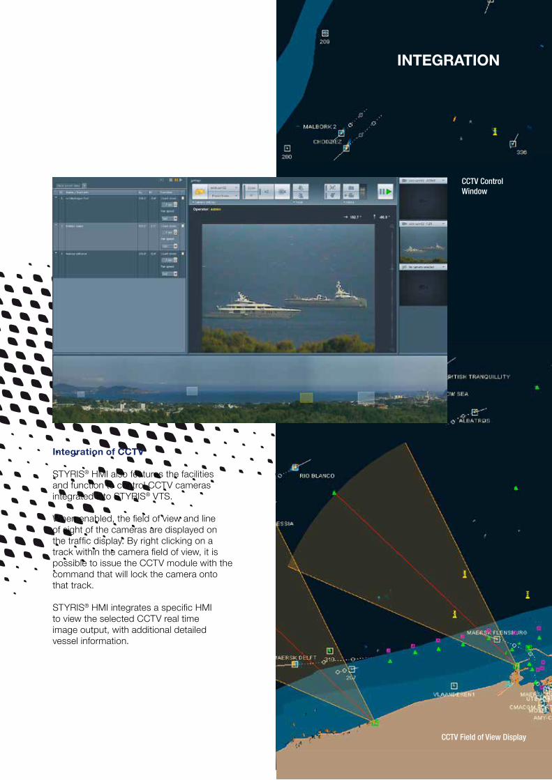
Integration of CCTV
STYRIS® HMI also features the facilities and function to control CCTV cameras integrated into STYRIS® VTS.
When enabled, the field of view and line of sight of the cameras are displayed on the traffic display. By right clicking on a track within the camera field of view, it is possible to issue the CCTV module with the command that will lock the camera onto that track.
STYRIS® HMI integrates a specific HMI to view the selected CCTV real time image output, with additional detailed vessel information.
IntegratIon
CCTV Field of View Display
CCTV Control Window

Communication system does not use expensive hardware matrix for mixing and distributing audio. All the processing and transfer is performed using the Ethernet network back bone and the processing of client computers.
There is no special cabling or audio transmission equipment dedicated to the VCS system. Therefore it is very easy to add, remove or modify the set of radios available to one operator. Use of IP transmission of voice enables retrieval of remote clients without the need for multiplexers and to benefit from alternate routing of data in case of failure of primary links.
Integration of radios
The Airbus Voice over IP (Internet Protocol) Communication System is designed and developed by Airbus. Integrated within STYRIS®, it provides a very efficient way to handle Voice Communications involved in maritime surveillance (HF/MF/VHF and GMDSS radio subsystems).
The Radio “Touch screen” HMI is dedicated to manage communications from a list of available radios stations and channels and some other media such as telephones. Using the latest technologies in terms of voice digitization and transfer, Airbus VoIP
HeadsetMicrophoneVGA
LAN
Radio over IP module
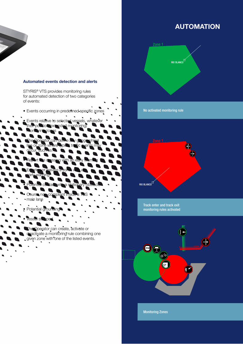
Automated events detection and alerts STYRIS® VTS provides monitoring rules for automated detection of two categories of events:
• Events occurring in predefined specific zones
• Events relative to selected vessels, whatever their position (extended monitoring) monitoring zones
The Operator can define any geographical line or zone where typical traffic events may occur, such as:
• Report line crossing with an early warning
• Entering or leaving a zone, with an early warning
• Potential contact with a stationary obstacle
• Course non-compliant inside a TSS main lane
• Potential grounding
• Vessel stopped
The Operator can create, activate or deactivate a monitoring rule combining one given zone with one of the listed events.
Zone 1
RIO BLANCO
AutomAtion
Zone 1
RIO BLANCO
No activated monitoring rule
Monitoring Zones
Track enter and track exitmonitoring rules activated
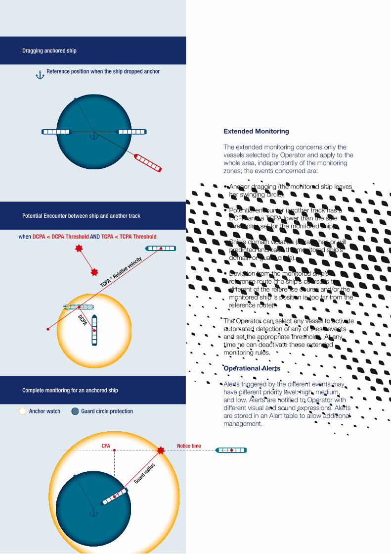
Extended Monitoring
The extended monitoring concerns only the vessels selected by Operator and apply to the whole area, independently of the monitoring zones; the events concerned are:
• Anchor dragging (the monitored ship leaves her swinging circle),
• Potential encounter (another track has a DCPA and a TCPA lower than the safe thresholds set for the monitored ship),
• Ship’s domain violation (a track has or will predicted encroach the monitored ship’s domain or guard circle).
• Deviation from the monitored ship’s reference route (the ship’s course is too different of the reference course and/or the monitored ship ’s position is too far from the reference route).
The Operator can select any vessel to activate automated detection of any of these events and set the appropriate thresholds. At any time he can deactivate these extended monitoring rules.
Operational Alerts
Alerts triggered by the different events may have different priority level: high, medium, and low. Alerts are notified to Operator with different visual and sound expressions. Alerts are stored in an Alert table to allow additional management.
TCPA * Relative
velocity
DCPA
Potential Encounter between ship and another track
when DCPA < DCPA Threshold AND TCPA < TCPA Threshold
Dragging anchored ship
Complete monitoring for an anchored ship
Swinging
radius
Reference position when the ship dropped anchor
Anchor watch Guard circle protection
Swinging
radius
Guard
radius
Notice timeCPA
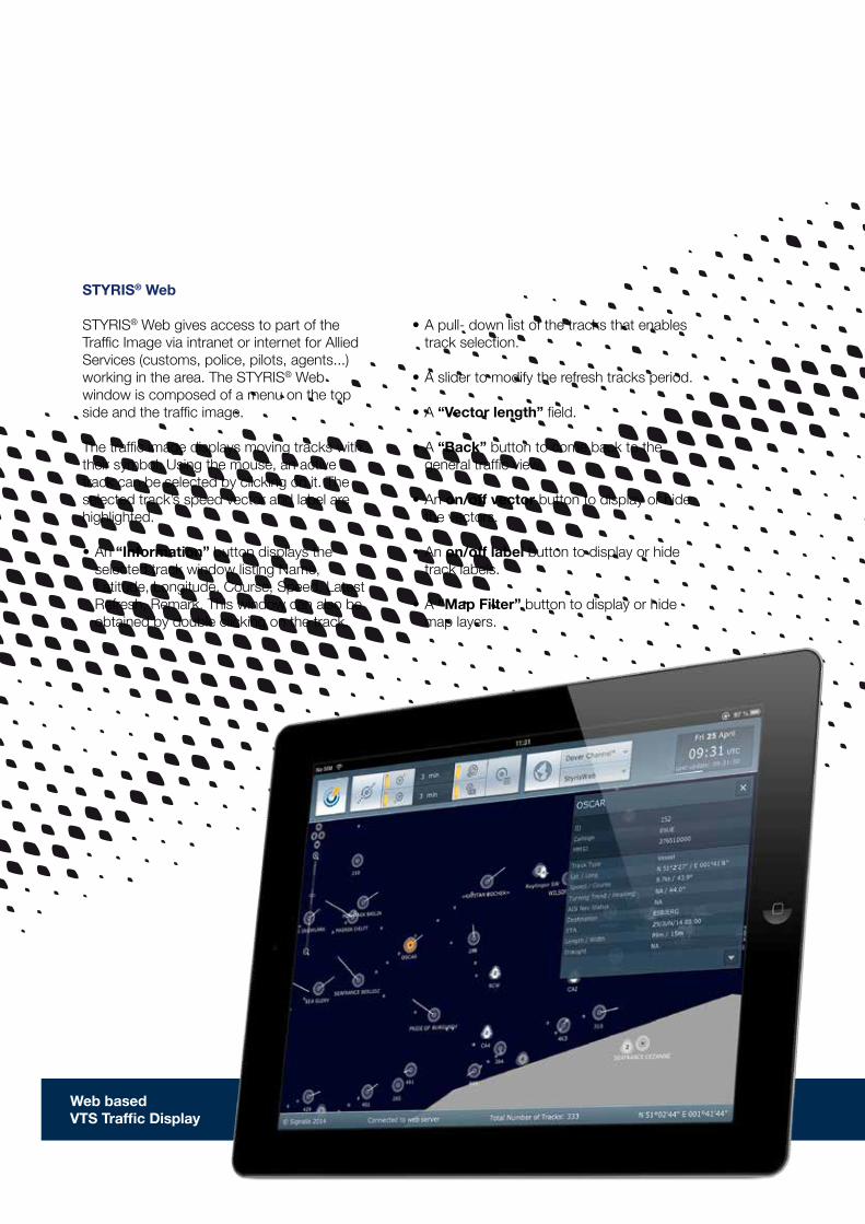
• A pull- down list of the tracks that enables track selection.
• A slider to modify the refresh tracks period.
• A “Vector length” field.
• A “Back” button to come back to the general traffic view.
• An on/off vector button to display or hide the vectors.
• An on/off label button to display or hide track labels.
• A “Map Filter” button to display or hide map layers.
STYRIS® Web
STYRIS® Web gives access to part of the Traffic Image via intranet or internet for Allied Services (customs, police, pilots, agents...) working in the area. The STYRIS® Web window is composed of a menu on the top side and the traffic image.
The traffic image displays moving tracks with their symbol. Using the mouse, an active track can be selected by clicking on it. The selected track’s speed vector and label are highlighted.
• An “Information” button displays the selected track window listing Name, Latitude, Longitude, Course, Speed, Latest Refresh, Remark. This window can also be obtained by double clicking on the track.
Web based VTS Traffic Display
ContactsAirbus Defence and Space9 rue Louis Rameau – B.P. 7010195873 Bezons CedexFrance
Airbus Defence and SpaceHanna-Kunath-Strasse 328199 BremenGermany
Airbus Defence and SpaceLa Ciotat Test FacilitiesZI Athelia 2, 220 impasse du Serpolet13704 La Ciotat CedexFrance
[email protected]: +33 1 39 96 44 44Germany: +49 421 48404 0
www.signalis.com
Airbus Defence and Space©Airbus Defence and Space. 2018 All rights reserved. Airbus, its logo and product names are registered trademarks. Reference 0489. May, 2018.