Embed Size (px)
Citation preview
* Corresponding author: [email protected]
Study on Structure Design of Generator of Flood Discharge Tunnel with Level Swirling Flow Heng Zhou1*, Hui Li2, Jing Liu1, Xinlei Guo3, Weiguo Wang1, Xi Lu1, Shengjie Di 1 1Power China, Northwest Engineering Corporation Limited, Xi’an, Shaanxi, 710065, China 2State Grid Gansu Electric Power Company, Lanzhou, 730070, China 3China Institute of Water Resources and Hydropower Research, Beijing, 10038, China
Abstract. Through the design of the Generator of the spillway tunnel, the safe operation efficiency of flood discharge tunnel with the level swirling flow is further improved. This paper takes the horizontal swirl spillway tunnel of Gongboxia Hydropower Station on the Yellow River as an example. First, the project hub facilities of the Gongboxia Hydropower Station are introduced. Moreover, the design of the gradient section and the spinning chamber section in the Generator is also studied. Based on the calculation scheme of structural mechanics, the internal force of the structure under various load combinations such as external water pressure and internal water pressure is calculated. According to Design Codes For Hydraulic Concrete Structure, the structural reinforcement is computed. These provide the basis for the design of the flood discharge tunnel with level swirling flow of large hydropower engineering facilities in Northwest China.
1 Introduction Gongboxia Hydropower Station on the Yellow River is the fourth large cascade hydropower station in the upper reaches of the Yellow River after the Longyangxia Hydropower Station, Laxiwa Lijiaxia Hydropower Station (Fig. 1,2). It is located at the junction of Xunhua County and Hualong County in Qinghai Province, 25 km from Xunhua County and 153 km from Xining City. It is mainly composed of a dam, diversion power generation system and flood discharge structure. Left side dam, right side dam and cross-strait seepage control works are used to connect the two sides. There are also irrigation outlets on the left and right banks. Buildings such as vertical shaft section, generator, cyclone section, plunge pool section and partial backwater section of horizontal cyclone spillway tunnel are located in reservoir area and bear large external water pressure [1-2]. In addition, the shape of the generator is complex [3]. When the plunge pond section is the gate tunnel type, the force distribution of the structure is not very uniform under the external water pressure. The value and distribution of the reduction coefficient of water pressure outside the reservoir area affect the size and reinforcement of the structure.
Now, research achievements on structural design of spillway tunnel of hydropower station are quite abundant, but there is still relatively little structural design around the generator [4-6]. This paper takes the horizontal swirl spillway tunnel of Gongboxia Hydropower Station on the Yellow River. Moreover, the design of the gradient section and the spinning chamber section in the Generator is also studied. The structural stress is
computed under different loads and reinforcement. Reinforcement recommendations were also suggested. These provide a reference for the design of the generator of a similar spillway tunnel.
Fig. 1. Panorama of Gongboxia Hydropower Station
E3S Web of Conferences 276, 02013 (2021) https://doi.org/10.1051/e3sconf/202127602013WCHBE 2021
© The Authors, published by EDP Sciences. This is an open access article distributed under the terms of the Creative Commons Attribution License 4.0 (http://creativecommons.org/licenses/by/4.0/).
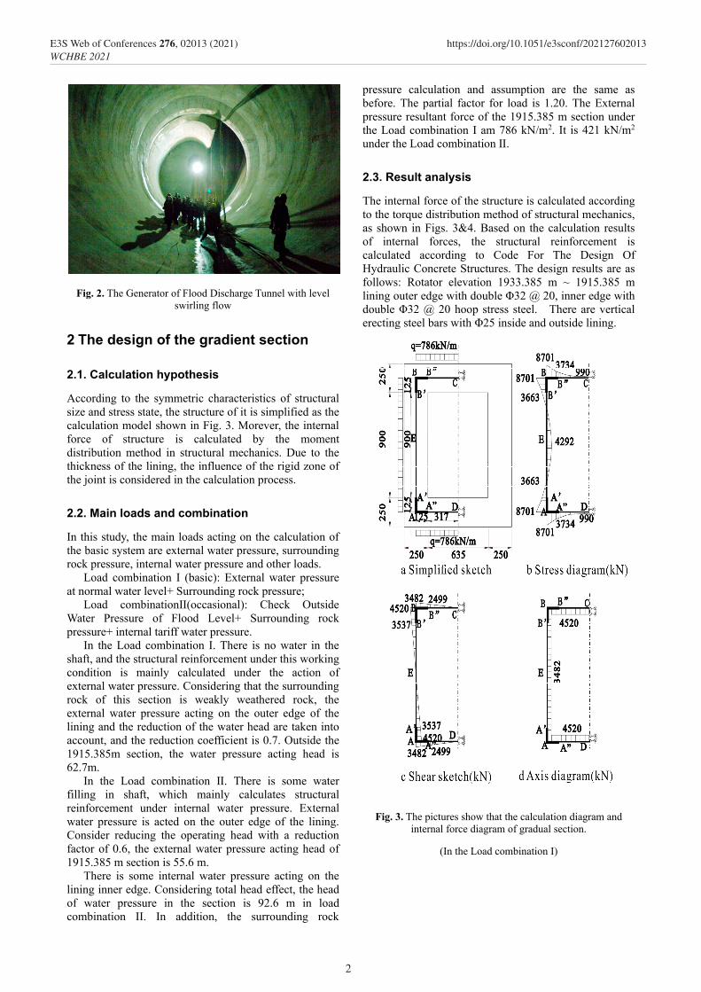
Fig. 2. The Generator of Flood Discharge Tunnel with level swirling flow
2 The design of the gradient section
2.1. Calculation hypothesis
According to the symmetric characteristics of structural size and stress state, the structure of it is simplified as the calculation model shown in Fig. 3. Morever, the internal force of structure is calculated by the moment distribution method in structural mechanics. Due to the thickness of the lining, the influence of the rigid zone of the joint is considered in the calculation process.
2.2. Main loads and combination
In this study, the main loads acting on the calculation of the basic system are external water pressure, surrounding rock pressure, internal water pressure and other loads.
Load combination I (basic): External water pressure at normal water level+ Surrounding rock pressure;
Load combinationⅡ(occasional): Check Outside Water Pressure of Flood Level+ Surrounding rock pressure+ internal tariff water pressure.
In the Load combination I. There is no water in the shaft, and the structural reinforcement under this working condition is mainly calculated under the action of external water pressure. Considering that the surrounding rock of this section is weakly weathered rock, the external water pressure acting on the outer edge of the lining and the reduction of the water head are taken into account, and the reduction coefficient is 0.7. Outside the 1915.385m section, the water pressure acting head is 62.7m.
In the Load combination Ⅱ. There is some water filling in shaft, which mainly calculates structural reinforcement under internal water pressure. External water pressure is acted on the outer edge of the lining. Consider reducing the operating head with a reduction factor of 0.6, the external water pressure acting head of 1915.385 m section is 55.6 m.
There is some internal water pressure acting on the lining inner edge. Considering total head effect, the head of water pressure in the section is 92.6 m in load combination II. In addition, the surrounding rock
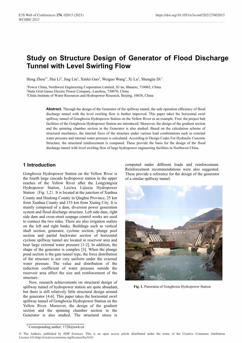
pressure calculation and assumption are the same as before. The partial factor for load is 1.20. The External pressure resultant force of the 1915.385 m section under the Load combination I am 786 kN/m2. It is 421 kN/m2 under the Load combination Ⅱ.
2.3. Result analysis
The internal force of the structure is calculated according to the torque distribution method of structural mechanics, as shown in Figs. 3&4. Based on the calculation results of internal forces, the structural reinforcement is calculated according to Code For The Design Of Hydraulic Concrete Structures. The design results are as follows: Rotator elevation 1933.385 m ~ 1915.385 m lining outer edge with double Φ32 @ 20, inner edge with double Φ32 @ 20 hoop stress steel. There are vertical erecting steel bars with Φ25 inside and outside lining.
Fig. 3. The pictures show that the calculation diagram and internal force diagram of gradual section.
(In the Load combination I)
2
E3S Web of Conferences 276, 02013 (2021) https://doi.org/10.1051/e3sconf/202127602013WCHBE 2021
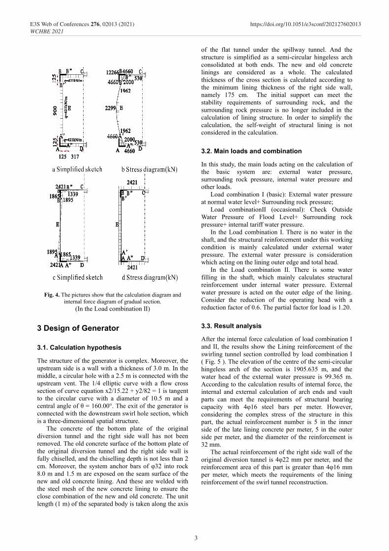
Fig. 4. The pictures show that the calculation diagram and internal force diagram of gradual section.
(In the Load combination Ⅱ)
3 Design of Generator
3.1. Calculation hypothesis
The structure of the generator is complex. Moreover, the upstream side is a wall with a thickness of 3.0 m. In the middle, a circular hole with a 2.5 m is connected with the upstream vent. The 1/4 elliptic curve with a flow cross section of curve equation x2/15.22 + y2/82 = 1 is tangent to the circular curve with a diameter of 10.5 m and a central angle of θ = 160.00°. The exit of the generator is connected with the downstream swirl hole section, which is a three-dimensional spatial structure.
The concrete of the bottom plate of the original diversion tunnel and the right side wall has not been removed. The old concrete surface of the bottom plate of the original diversion tunnel and the right side wall is fully chiselled, and the chiselling depth is not less than 2 cm. Moreover, the system anchor bars of φ32 into rock 8.0 m and 1.5 m are exposed on the seam surface of the new and old concrete lining. And these are welded with the steel mesh of the new concrete lining to ensure the close combination of the new and old concrete. The unit length (1 m) of the separated body is taken along the axis
of the flat tunnel under the spillway tunnel. And the structure is simplified as a semi-circular hingeless arch consolidated at both ends. The new and old concrete linings are considered as a whole. The calculated thickness of the cross section is calculated according to the minimum lining thickness of the right side wall, namely 175 cm. The initial support can meet the stability requirements of surrounding rock, and the surrounding rock pressure is no longer included in the calculation of lining structure. In order to simplify the calculation, the self-weight of structural lining is not considered in the calculation.
3.2. Main loads and combination
In this study, the main loads acting on the calculation of the basic system are: external water pressure, surrounding rock pressure, internal water pressure and other loads.
Load combination I (basic): External water pressure at normal water level+ Surrounding rock pressure;
Load combinationⅡ (occasional): Check Outside Water Pressure of Flood Level+ Surrounding rock pressure+ internal tariff water pressure.
In the Load combination I. There is no water in the shaft, and the structural reinforcement under this working condition is mainly calculated under external water pressure. The external water pressure is consideration which acting on the lining outer edge and total head.
In the Load combination Ⅱ. There is some water filling in the shaft, which mainly calculates structural reinforcement under internal water pressure. External water pressure is acted on the outer edge of the lining. Consider the reduction of the operating head with a reduction factor of 0.6. The partial factor for load is 1.20.
3.3. Result analysis
After the internal force calculation of load combination I and II, the results show the Lining reinforcement of the swirling tunnel section controlled by load combination I ( Fig. 5 ). The elevation of the centre of the semi-circular hingeless arch of the section is 1905.635 m, and the water head of the external water pressure is 99.365 m. According to the calculation results of internal force, the internal and external calculation of arch ends and vault parts can meet the requirements of structural bearing capacity with 4φ16 steel bars per meter. However, considering the complex stress of the structure in this part, the actual reinforcement number is 5 in the inner side of the late lining concrete per meter, 5 in the outer side per meter, and the diameter of the reinforcement is 32 mm.
The actual reinforcement of the right side wall of the original diversion tunnel is 4φ22 mm per meter, and the reinforcement area of this part is greater than 4φ16 mm per meter, which meets the requirements of the lining reinforcement of the swirl tunnel reconstruction.
3
E3S Web of Conferences 276, 02013 (2021) https://doi.org/10.1051/e3sconf/202127602013WCHBE 2021
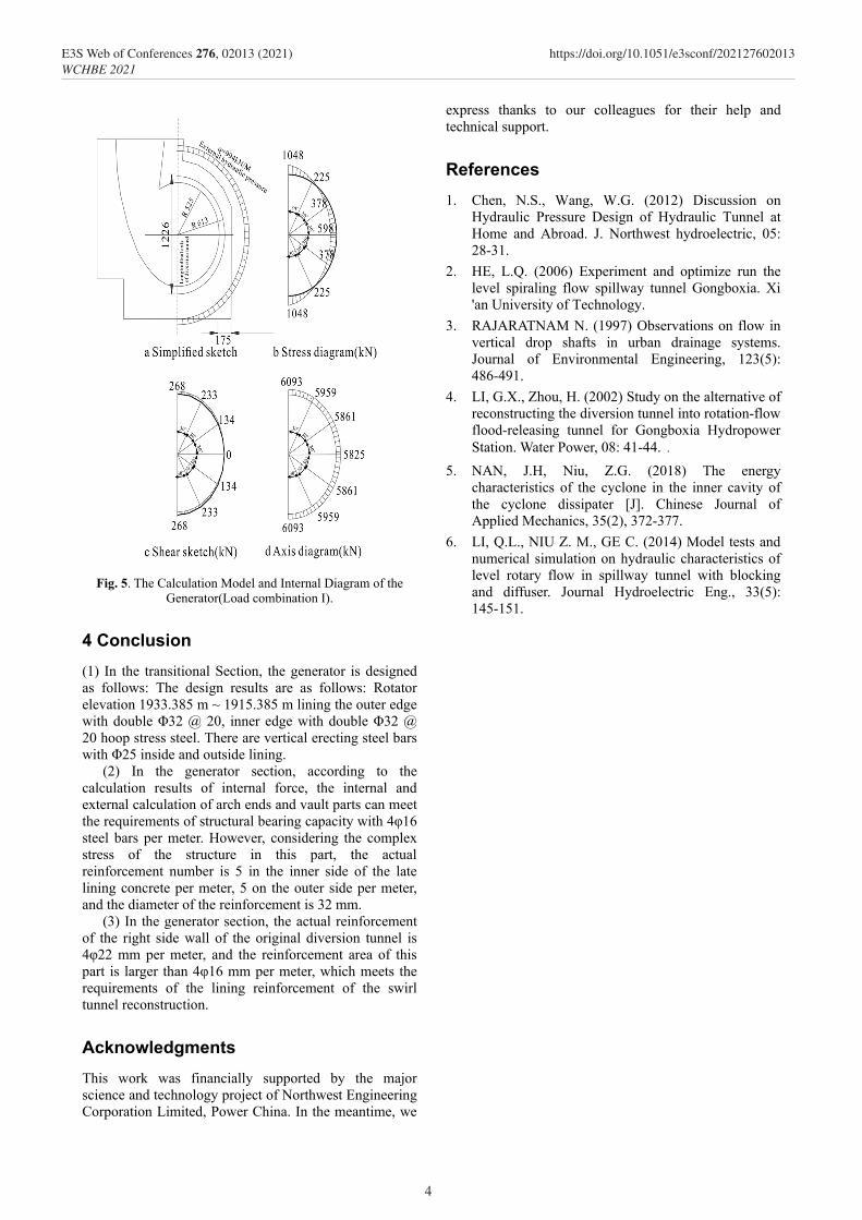
Fig. 5. The Calculation Model and Internal Diagram of the Generator(Load combination I).
4 Conclusion (1) In the transitional Section, the generator is designed as follows: The design results are as follows: Rotator elevation 1933.385 m ~ 1915.385 m lining the outer edge with double Φ32 @ 20, inner edge with double Φ32 @ 20 hoop stress steel. There are vertical erecting steel bars with Φ25 inside and outside lining.
(2) In the generator section, according to the calculation results of internal force, the internal and external calculation of arch ends and vault parts can meet the requirements of structural bearing capacity with 4φ16 steel bars per meter. However, considering the complex stress of the structure in this part, the actual reinforcement number is 5 in the inner side of the late lining concrete per meter, 5 on the outer side per meter, and the diameter of the reinforcement is 32 mm.
(3) In the generator section, the actual reinforcement of the right side wall of the original diversion tunnel is 4φ22 mm per meter, and the reinforcement area of this part is larger than 4φ16 mm per meter, which meets the requirements of the lining reinforcement of the swirl tunnel reconstruction.
Acknowledgments This work was financially supported by the major science and technology project of Northwest Engineering Corporation Limited, Power China. In the meantime, we
express thanks to our colleagues for their help and technical support.
References 1. Chen, N.S., Wang, W.G. (2012) Discussion on
Hydraulic Pressure Design of Hydraulic Tunnel at Home and Abroad. J. Northwest hydroelectric, 05: 28-31.
2. HE, L.Q. (2006) Experiment and optimize run the level spiraling flow spillway tunnel Gongboxia. Xi 'an University of Technology.
3. RAJARATNAM N. (1997) Observations on flow in vertical drop shafts in urban drainage systems. Journal of Environmental Engineering, 123(5): 486-491.
4. LI, G.X., Zhou, H. (2002) Study on the alternative of reconstructing the diversion tunnel into rotation-flow flood-releasing tunnel for Gongboxia Hydropower Station. Water Power, 08: 41-44..
5. NAN, J.H, Niu, Z.G. (2018) The energy characteristics of the cyclone in the inner cavity of the cyclone dissipater [J]. Chinese Journal of Applied Mechanics, 35(2), 372-377.
6. LI, Q.L., NIU Z. M., GE C. (2014) Model tests and numerical simulation on hydraulic characteristics of level rotary flow in spillway tunnel with blocking and diffuser. Journal Hydroelectric Eng., 33(5): 145-151.
4
E3S Web of Conferences 276, 02013 (2021) https://doi.org/10.1051/e3sconf/202127602013WCHBE 2021