Embed Size (px)
Citation preview
International Research Journal of Engineering and Technology (IRJET) e-ISSN: 2395-0056
Volume: 05 Issue: 06 | June 2018 www.irjet.net p-ISSN: 2395-0072
© 2018, IRJET | Impact Factor value: 7.211 | ISO 9001:2008 Certified Journal | Page 2040
STUDY OF THE STRESS IN THE OIL PIPE FLANGE COUPLING
Mr. Manjunath kamatagi1, Dr. S N Kurbet2
1M.Tech in Machine design, Department of Mechanical Engineering, Basaveshwar Engineering College, Bagalkot,
Karnataka, India`
2Professor and HOD of Mechanical Engineering, Basaveshwar Engineering College, Bagalkot, Karnataka, India
---------------------------------------------------------------------***---------------------------------------------------------------------
Abstract - With the increasing demand for the automotive, the need for the fuel is increasing. With this, the demand for extracting crude oil is eminent. The crude oil is extracted from deep under the sea underground. This is done by drilling the oil wells deep into the sea ground. During the process of the drilling the pipes along with the drill bit are penetrated into the sea ground. As the depth increases the pipes are to be coupled with the flanges with the appropriate bolt pre-tensions. The current scope of the work is to analyze the stress developed in the flanges due to bolt pre-tensioning and torque applied on the pipe.
Key Words: Flange Coupling, Pre-tensioning, CAD, FEA, Hyper-mesh.
1. INTRODUCTION Coupling is a device which helps to attach two shafts together at their ends for the reason of transmitting power. Normally the drive elements are known as shafts. During the process of oil transportation, it is very necessary to connect the two shafts according to the applications with the help of nut and bolts, and it must be predetermined that, the kind of load will apply on the bolts and also the amount of stress induced on the coupling.
1.1 INTRODUCTION TO OIL PIPE COUPLINGS
The Oil flanged coupling makes it easier to disconnect the pipes when needed, while still withstanding the operating pressure during operation. For low pressure applications, a compression coupler may be used to allow disconnection and reconnection. The material of a flange is basically set during the choice of the pipe in most of the cases. Normally a flange is made up of the same material as the pipe depending upon the applications.
2. LITERATURE REVIEW The purpose of the literature survey is to study the works of different researchers concerned with the detailed study of the stress in the oil pipe flange coupling. Also find out the scope for any new methods of design by which the design
process is made simple, less time consuming and cost effective. Saurav Rajgadia, et al [1] The study of present paper is to decrease the maximum shear stress by choosing a proper material meant for the flange coupling. For this reason, modeling of the flange coupling is carried out in Solid works. And analyze in ansys work bench software. Kondru Nagendra Babu, et al [2] the present study of this paper is to reduce the stresses that are acting on the coupling bolts by providing the equal strength on it. Any how the shank portion the bolt is smaller in size than the threaded part of the bolt therefore the threaded part will take higher loads which will results in failure. Somvir Singh, et al [3] now a days the every manufacturing industry has a challenge to increase the strength to weight ratio of the component. In the present study the researcher objective is to decrease the weight of the flange coupling. And for this work the researcher chose the composite material of aluminum silicon carbide for the flange coupling because this material has lighter density. The purpose of this paper is to reduce the weight of the flange coupling without affecting the performance and also to minimize the cost of the material.
2.1 OUTCOMES FROM LITERATURE SURVEY
After the literature survey it was found that, the stress analysis of rigid flange couplings subjected to static load conditions was done in most cases by applying different boundary conditions. Work is carried out to reduce stress by selecting a suitable flange material. The current scope of the work is to analyze the stress developed in the flanges due to bolt pre-tensioning and torque applied on the pipe. To conduct the root causes analysis for the failure of the flange
coupling.
2.2 OBJECTIVES
To analyse the stress plots of oil pipe flange coupling for the given load conditions, to modify the coupling sections to
meet the required factor of safety.
International Research Journal of Engineering and Technology (IRJET) e-ISSN: 2395-0056
Volume: 05 Issue: 06 | June 2018 www.irjet.net p-ISSN: 2395-0072
© 2018, IRJET | Impact Factor value: 7.211 | ISO 9001:2008 Certified Journal | Page 2041
2.3 METHODOLOGY
The project initiated through the Complain from the field workers about the failure of the flange coupling at irregular interval of the operation. The exact cause for the failure was not known even after maintaining the standard drilling feed. So the inputs were collected from the field failure were in the following operating parameters along with the geometrical dimensions.
Operating parameters - Speed from the motor (rpm) - Horse power of the motor (Hp)
Geometrical dimensions - The internal diameter of the flange is 200
mm diameter. - Thickness of the flange 35 mm - Bolt diameter of 15.5 mm - The geometry of the flange with
Above dimensions are created using Hyper-mesh software. The commands like solid spin, solid drag are used to create geometry. The geometry is followed by pre-processing to create HEXA and PENTA elements which are of the first order element. The flat flange region with bolt holes surface is meshed to form 2D shell elements. The holes of a bolt are modeled circle around circle quad patterns even number of elements are maintained at the circular hole region this pattern helps to distribute the stress uniformly over the bolt. 2D shell mesh created, on the flange surface are dragged to a length of 35mm to create HEXA/PENTA elements with a four layers across the thickness. The hub region of the flange is a conical shape and has to be meshed with the spin option command. To perform this, the flange cross section hub is modeled with 2D mixed element maintain the minimum 3 elements across the thickness. Then the spin option is used to form 3D HEXA and PENTA elements. Similarly the bolts are also modeled with the 3D elements. Contact surface elements are deleting to define frictional contact behavior between the two faces of the flange. Similarly the contact behavior is defined between bolts and flange
3 .RESULTS AND DISCUSSIONS
The flange analysis is carried out for six different loading conditions and maximum von mises stress and maximum principle stress are observed in the bolt location on the coupling, when the pre tension load is 6250 N and the torque applied is 350 MPA
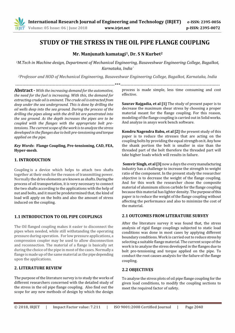
CAD model
Fig – 3.1: CAD model
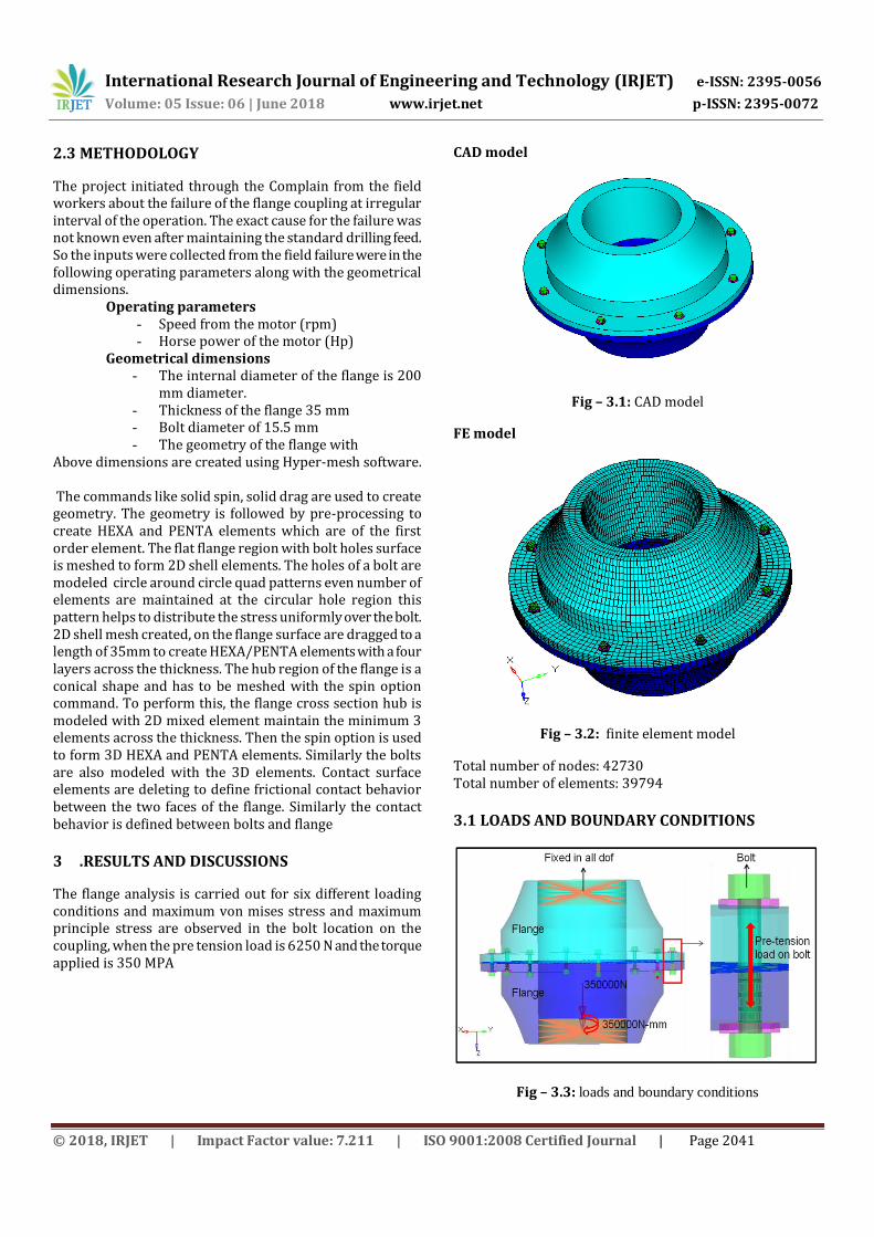
FE model
Fig – 3.2: finite element model
Total number of nodes: 42730 Total number of elements: 39794
3.1 LOADS AND BOUNDARY CONDITIONS
Fig – 3.3: loads and boundary conditions
International Research Journal of Engineering and Technology (IRJET) e-ISSN: 2395-0056
Volume: 05 Issue: 06 | June 2018 www.irjet.net p-ISSN: 2395-0072
© 2018, IRJET | Impact Factor value: 7.211 | ISO 9001:2008 Certified Journal | Page 2042
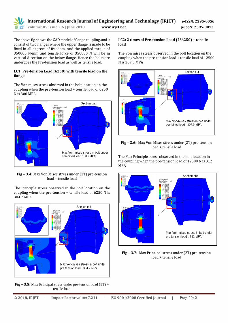
The above fig shows the CAD model of flange coupling, and it consist of two flanges where the upper flange is made to be fixed in all degrees of freedom. And the applied torque of 350000 N-mm and tensile force of 350000 N will be in vertical direction on the below flange. Hence the bolts are undergoes the Pre-tension load as well as tensile load. LC1: Pre-tension Load (6250) with tensile load on the flange The Von mises stress observed in the bolt location on the coupling when the pre-tension load + tensile load of 6250 N is 300 MPA .
Fig – 3.4: Max Von Mises stress under (1T) pre-tension load + tensile load
The Principle stress observed in the bolt location on the coupling when the pre-tension + tensile load of 6250 N is 304.7 MPA.
Fig – 3.5: Max Principal stress under pre-tension load (1T) +
tensile load
LC2: 2 times of Pre-tension Load (2*6250) + tensile load The Von mises stress observed in the bolt location on the coupling when the pre-tension load + tensile load of 12500 N is 307.5 MPA
Fig – 3.6: Max Von Mises stress under (2T) pre-tension load + tensile load
The Max Principle stress observed in the bolt location in the coupling when the pre-tension load of 12500 N is 312 MPA
Fig – 3.7: Max Principal stress under (2T) pre-tension load + tensile load
International Research Journal of Engineering and Technology (IRJET) e-ISSN: 2395-0056
Volume: 05 Issue: 06 | June 2018 www.irjet.net p-ISSN: 2395-0072
© 2018, IRJET | Impact Factor value: 7.211 | ISO 9001:2008 Certified Journal | Page 2043
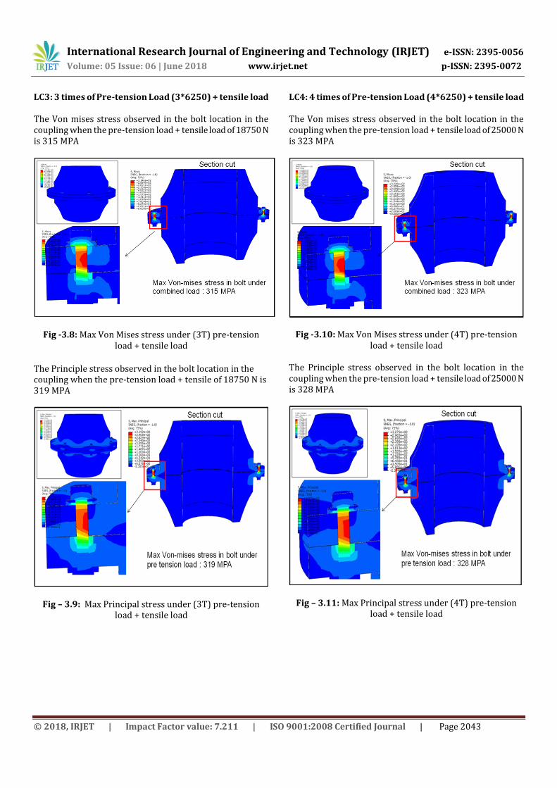
LC3: 3 times of Pre-tension Load (3*6250) + tensile load The Von mises stress observed in the bolt location in the coupling when the pre-tension load + tensile load of 18750 N is 315 MPA
Fig -3.8: Max Von Mises stress under (3T) pre-tension load + tensile load
The Principle stress observed in the bolt location in the coupling when the pre-tension load + tensile of 18750 N is 319 MPA
Fig – 3.9: Max Principal stress under (3T) pre-tension load + tensile load
LC4: 4 times of Pre-tension Load (4*6250) + tensile load The Von mises stress observed in the bolt location in the coupling when the pre-tension load + tensile load of 25000 N is 323 MPA
Fig -3.10: Max Von Mises stress under (4T) pre-tension load + tensile load
The Principle stress observed in the bolt location in the coupling when the pre-tension load + tensile load of 25000 N is 328 MPA
Fig – 3.11: Max Principal stress under (4T) pre-tension load + tensile load

International Research Journal of Engineering and Technology (IRJET) e-ISSN: 2395-0056
Volume: 05 Issue: 06 | June 2018 www.irjet.net p-ISSN: 2395-0072
© 2018, IRJET | Impact Factor value: 7.211 | ISO 9001:2008 Certified Journal | Page 2044
LC5: 5 times of Pre-tension Load (5*6250) + tensile load
The Principle stress observed in the bolt location in the coupling when the pre-tension + tensile load of 31250 N is 366 MPA
Fig – 3.12: Max Principle stress under (5T) pre-tension load + tensile load
The Principle stress observed in the bolt location in the coupling when the pre-tension + tensile load of 31250 N is 367 MPA
Fig – 3.13: Max Principal stress under (5T) pre-tension load + tensile load
3.2 RESULT SUMMARY Table- 3.1 result summary
4. CONCLUSION AND FUTURE SCOPE
4.1 Observation and conclusion
From the result summary table, it is observed that the stress the bolt is increasing as the bolt tightening torque (pre-tension load) is increasing. The max stress in the oil drill coupling is observed at the bolt location as shown in the table. The max yield strength of the coupling is 355 MPA. The coupling is safe as far as the pre-tension load is within 25000 N. Beyond 25000N pre-tension load, the coupling is not safe and hence proper care has to be taken while tightening the bolt.
3.3 FUTURE SCOPE Since the current project is field failure problem, a root cause analysis of investigation is carried out considering pre tension load as a variable parameter. Hence an investigator can take a speed as a variable parameter and conduct an analysis investigation.
3.4 REFERENCES [1] Saurav Rajgadia et. al, “Design and Stress-Analysis of a
Rigid Flange Coupling using FEM”, International journal of professional engineering studies. Vol. 4, Issue 10. 2015
[2] Kondru Nagendra Babu et. al, “Design and Failure Analysis of Flange Coupling with Uniform Strengthen Bolts”, International journal of professional engineering studies. Vol. 6, Issue 1. 2017
[3] Somvir Singh et. al, “Finite Element Analysis and Weight
Reduction of Flange Coupling Using CAE Tools”, international journal of professional engineering studies. Vol. 03, Issue 4. 2017
Load case
Pre-tension load
Combined load (Pre-tension + External load)
YS (MPA)
Max Stress (MPA)
FOS
Max
Principal
Von-
Mises Max Principal
Von-
Mises
LC1 38.5 39 304.7 300 350 304.7 1.15
LC2 77 78 312 307.5 350 312 1.12
LC3 115 117 319 315 350 319 1.10
LC4 154 156 328 323 350 328 1.07
LC5 269 273 367 366 350 367 0.95