Embed Size (px)
Citation preview

ENGLISHHEBREW
PLIDCO® FLANGE+COUPLINGINSTALLATION INSTRUCTIONS
LANGUAGES:CLICK ON LANGUAGE DESIRED
PLIDCO – The Pipe Line Development Companywww.plidco.com | (440) 871-5700 | [email protected] Canterbury Rd., Westlake, OH 44145
Page 1 of 12 IP-007 Revision 1
The Pipe Line Development Company 870 Canterbury Road • Westlake, Ohio 44145 Phone: (440) 871-5700 • Fax: (440) 871-9577
Toll Free: 1-800-848-3333 web: www.plidco.com • e-mail: [email protected]
PLIDCO® FLANGE+COUPLING INSTALLATION INSTRUCTIONS
!! WARNING!!
IMPROPER SELECTION OR USE OF THIS PRODUCT CAN RESULT IN EXPLOSION, FIRE, DEATH, PERSONAL INJURY, PROPERTY DAMAGE AND/OR HARM TO THE ENVIRONMENT.
READ CAREFULLY
The person in charge of the installation must be familiar with these instructions and communicate them to all personnel involved. Do not use or select a PLIDCO Flange+Coupling until all aspects of the application are thoroughly analyzed. Do not use the PLIDCO Flange+Coupling until you read and understand these installation instructions. Every effort has been made to securely package this product prior to shipment. Thoroughly inspect for any damage that may have occurred during shipment. If you have any questions, or encounter any difficulties using this product, please contact:
PLIDCO “DEPARTMENT 100” at 440-871-5700 toll free U.S. & Canada at 800-848-3333
Safety Check List
❑ Read and follow these instructions carefully. Follow your company’s safety policy and applicable codes and standards.
❑ Whenever a PLIDCO product is modified in any form including changing seals by anyone other than the Engineering and Manufacturing Departments of The Pipe Line Development Company or a PLIDCO certified repacking company, the product warranty is voided. Products that are field modified do not have the benefit of the material traceability, procedural documentation, quality inspection and experienced workmanship that are employed by The Pipe Line Development Company.
❑ Be absolutely certain that the correct seal material has been selected for the intended use. Contact PLIDCO or an authorized PLIDCO distributor if there are any questions about the seal compatibility with the pipeline chemicals and temperatures.
❑ During the Pipe Preparation and Installation procedures, those installing the PLIDCO Flange+Coupling must wear, at minimum, Z87+ safety eyewear and steel toe safety footwear.
❑ Determine the type of joint that the PLIDCO Flange+Coupling is expected to connect. See (a) and (b) below and determine the appropriate maximum allowable operating pressure (MAOP) from the ratings listed on the label of the PLIDCO Flange+Coupling.
Page 2 of 12 IP-007 Revision 1
(a) Pipe Unanchored
A PLIDCO Flange+Coupling is considered Unanchored only if it is installed with the clamp and thrust screws, and not welded to the pipe or installed with any other appropriate means of limiting pipe movement and end pull forces.
(b) Anchored Pipe
A PLIDCO Flange+Coupling is considered Anchored if it is welded to the pipe line, or the end pull forces are restricted by other means.
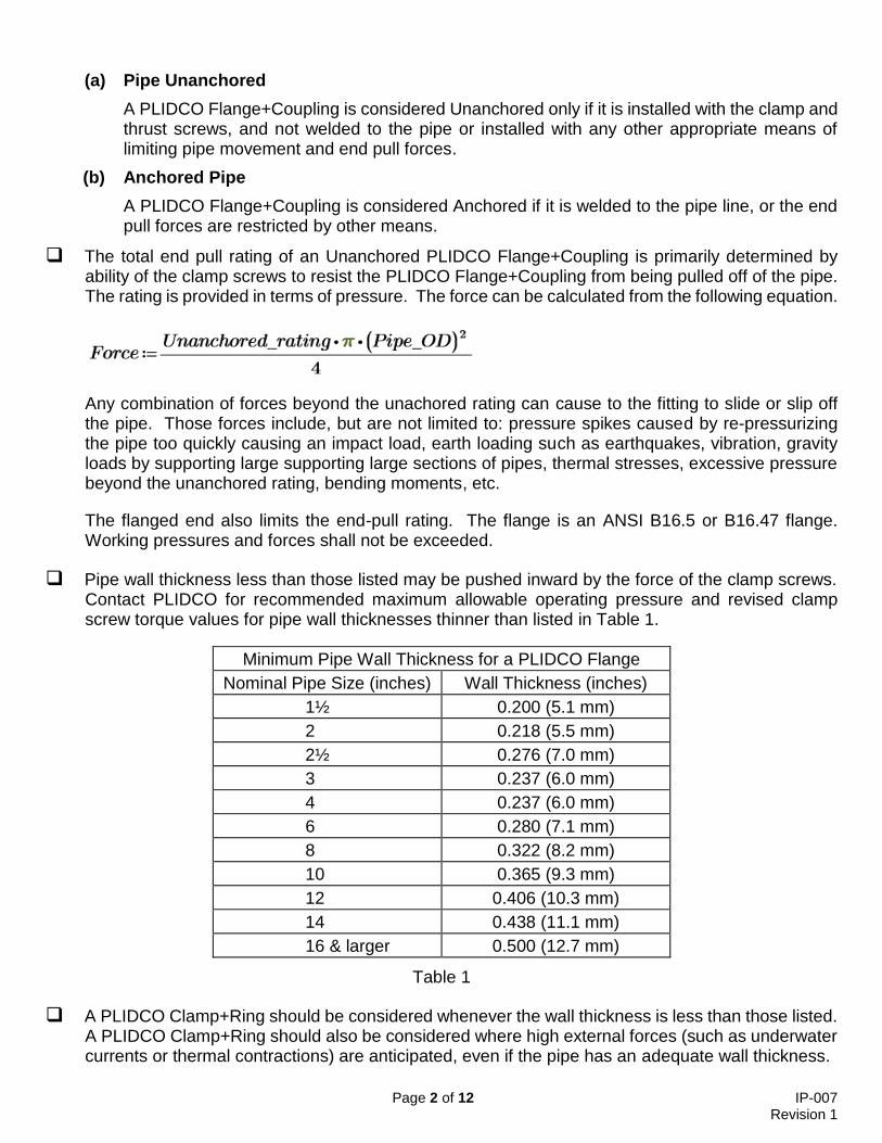
❑ The total end pull rating of an Unanchored PLIDCO Flange+Coupling is primarily determined by ability of the clamp screws to resist the PLIDCO Flange+Coupling from being pulled off of the pipe. The rating is provided in terms of pressure. The force can be calculated from the following equation.
Any combination of forces beyond the unachored rating can cause to the fitting to slide or slip off the pipe. Those forces include, but are not limited to: pressure spikes caused by re-pressurizing the pipe too quickly causing an impact load, earth loading such as earthquakes, vibration, gravity loads by supporting large supporting large sections of pipes, thermal stresses, excessive pressure beyond the unanchored rating, bending moments, etc.
The flanged end also limits the end-pull rating. The flange is an ANSI B16.5 or B16.47 flange. Working pressures and forces shall not be exceeded.
❑ Pipe wall thickness less than those listed may be pushed inward by the force of the clamp screws. Contact PLIDCO for recommended maximum allowable operating pressure and revised clamp screw torque values for pipe wall thicknesses thinner than listed in Table 1.
Minimum Pipe Wall Thickness for a PLIDCO Flange
Nominal Pipe Size (inches) Wall Thickness (inches)
1½ 0.200 (5.1 mm)
2 0.218 (5.5 mm)
2½ 0.276 (7.0 mm)
3 0.237 (6.0 mm)
4 0.237 (6.0 mm)
6 0.280 (7.1 mm)
8 0.322 (8.2 mm)
10 0.365 (9.3 mm)
12 0.406 (10.3 mm)
14 0.438 (11.1 mm)
16 & larger 0.500 (12.7 mm)
Table 1
❑ A PLIDCO Clamp+Ring should be considered whenever the wall thickness is less than those listed. A PLIDCO Clamp+Ring should also be considered where high external forces (such as underwater currents or thermal contractions) are anticipated, even if the pipe has an adequate wall thickness.
Page 3 of 12 IP-007 Revision 1
❑ Pipelines should be carefully supported or restrained at elbows and bends to prevent pullouts caused by internal and external forces; or a PLIDCO Clamp+Ring should be used. The pipeline should be evenly supported before re-pressuring. Follow applicable B31 codes during re-pressuring.
❑ If the PLIDCO Flange+Coupling is welded according to these instructions, or a suitable PLIDCO Clamp+Ring is used, it can be considered an anchored joint.
❑ Observe the pressure and temperature ratings on the label of the PLIDCO Flange+Coupling. Re-pressuring should be accomplished slowly and steadily without surges that could vibrate the pipeline and fitting or pull the fitting off the pipe. Industry codes and standards are a good source of information on this subject. Except for testing purposes, do not exceed the design pressure of the PLIDCO+Flange. Refer to the section on Field Testing for precautions. Personnel should not be allowed near the installation until the seal has been proven.
❑ Accurate clamp screw torque values are very important when the PLIDCO Flange+Coupling is used on a pipeline joint that is UNANCHORED. Do not exceed the Pipe Unanchored rating listed on the label of the PLIDCO+Flange until subsequent welding has been completed or the pipe is anchored by other means, such as a PLIDCO Clamp+Ring. FAILURE TO DO SO CAN RESULT IN EXPLOSION, FIRE, DEATH, PERSONAL INJURY, PROPERTY DAMAGE AND/OR HARM TO THE ENVIRONMENT.
Pipe Preparation
1. The pipe surface in the area under and around where the seals should be clean, free of coating and burrs, and lubricated to prevent abrasion to the seals. The area should be blasted to near-white finish, as noted in SSPC-SP10 / NACE No.2, is preferred. The cleaner the pipe the more positive the seal.
2. The seal can tolerate minor surface irregularities up to ± 1/32 inch (0.8 mm). High weld reinforcement or steeply sided welds will need to be ground flush with the pipe outside diameter surface.
3. Pipe outside diameter tolerance is as follows: Nominal pipe size 6-inch and smaller; ± 1% of the nominal diameter Greater than 6-inch through 14-inch; + 1/16 inch (1.6 mm), - 1/8 inch (3.2 mm) Greater than 14-inch nominal diameter; ± 5/32 inch (4.0 mm)
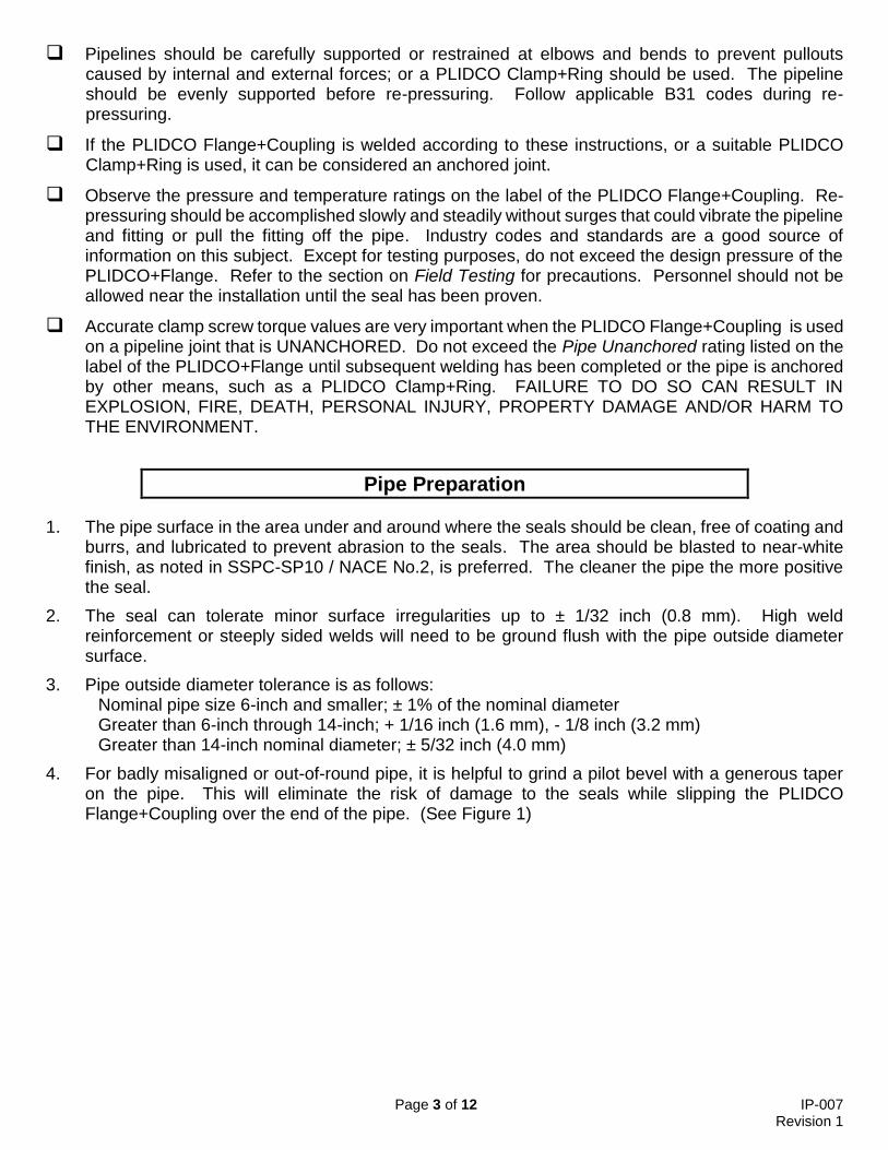
4. For badly misaligned or out-of-round pipe, it is helpful to grind a pilot bevel with a generous taper on the pipe. This will eliminate the risk of damage to the seals while slipping the PLIDCO Flange+Coupling over the end of the pipe. (See Figure 1)
Page 4 of 12 IP-007 Revision 1
Figure 1
Page 5 of 12 IP-007 Revision 1
Installation
The seals can be damaged by careless handling. Lifting devices such as chains, cables or lift truck forks should not contact the seals. Failure to do so can result in the seals being damaged, or pulled from their grooves.
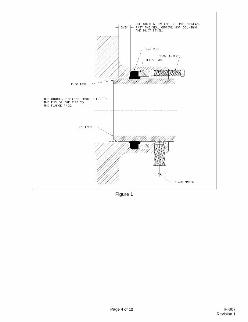
1. Measure and record dimension “D”, as shown in Figure 2. This will be needed later if the PLIDCO+Flange is welded to the pipe.
Figure 2
Page 6 of 12 IP-007 Revision 1
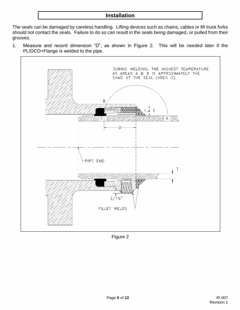
2. Coat all exposed surfaces of the seal material with a lubricant. Table 2 indicates the lubricants that are recommended for the various seal materials. The customer must determine if the lubricant is compatible with the product in the pipeline.
Petroleum based lubricants = A
Silicone based lubricants = B
Glycerin based lubricants = C
Super Lube® Grease (1) = D
Temperature (2)
Buna-N A, B, C, D 225°F (107°C)
Viton A, B, C, D 250°F (121°C)
Silicone C, D 300°F (149°C)
Neoprene B, C, D 250°F (121°C)
Aflas A, B, C, D 225°F (107°C)
Hycar A, B, C, D 180°F (82°C)
(1) Super Lube® Grease is a product of Synco Chemical Corporation. (www.super-lube.com)
(2) Temperature limit is for the seal material only and does not imply the pressure rating is necessarily applicable at this limit.
Table 2
NOTE: Do not use a lubricant for underwater applications. Sand, silt or debris could adhere to the lubricant affecting the sealing ability and the accuracy of the torque values.
3. Slide the pipe into the PLIDCO Flange+Coupling so that the end of the pipe is at least 5/8 inch (15.9 mm) past the seal ring (not counting the pilot bevel). The distance from the end of the pipe to the flange face shall not be less than 1/2 inch (12.7 mm). (See Figure 1)
4. Center the PLIDCO+Flange to the pipe. Advance the clamp screws to obtain equal spacing and stick out between the inner diameter of the PLIDCO Flange+Coupling and the outer diameter of the pipe.
5. Install and tighten the flange bolts per ASME PCC-1 before the clamp screws and thrust screws are fully tightened. This is critical if the pipes or components being joined are not free to move. Tightening the flange bolts after the clamp and thrust screws will drag the clamp screw cup points and seal along the pipe, causing damage to both.
6. Determine which clamp screw size is being used, measure the diameter of the threaded end of the clamp screw (measured in inches). As noted in the Safety Check List, contact PLIDCO for the maximum allowable operating pressure and the revised clamp screw torque value for thin wall pipe.
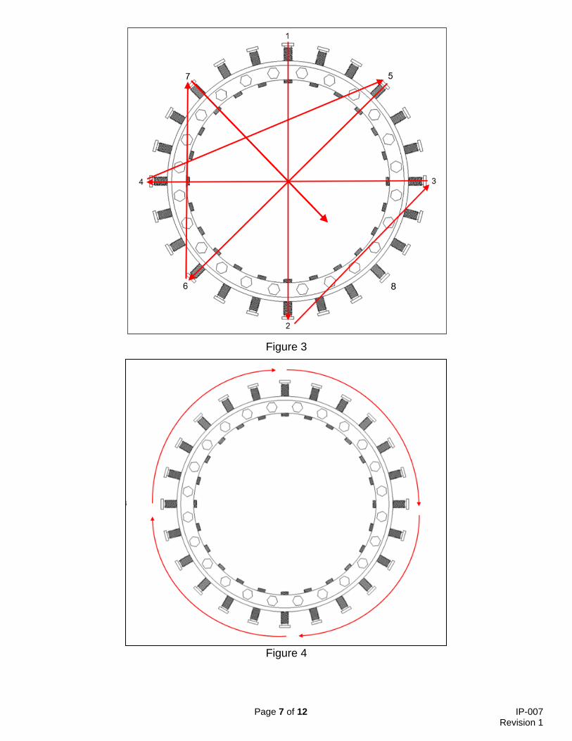
7. Clamp screws must be tightened evenly, maintaining an equal space between the pipe and the coupling using the recommended torque values. Tighten the clamp screws one at a time (torque values in Table 3) in a repeated sequence that matches Figure 3. The first time through the sequence, tighten the screws to 25% of the minimum torque. The second time through, tighten the screws to 50% minimum torque. The third time through, tighten the screws at 100% torque. Then, repeat the sequence at 100% torque until the clamp screws are unable to continue spinning (see Table 4 for torque percentage for each sequence).
Page 7 of 12 IP-007 Revision 1
Figure 3
Figure 4
Page 8 of 12 IP-007 Revision 1
Wrench Opening Cup Point Minimum Torque
Across Flats
(inches)
Clamp Screws
(inches) (ft-lbf) (Nm)
15/16 5/8-11 100 136
1 3/4-10 150 204
Table 3
Number of Times Through Torque Sequence
Percentage of Minimum Torque
1 25%
2 50%
3 100%
4+ (Circular Sequence) 100%
Table 4
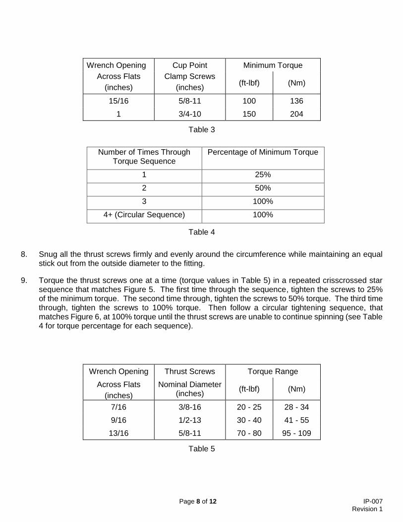
8. Snug all the thrust screws firmly and evenly around the circumference while maintaining an equal stick out from the outside diameter to the fitting.
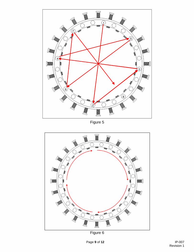
9. Torque the thrust screws one at a time (torque values in Table 5) in a repeated crisscrossed star sequence that matches Figure 5. The first time through the sequence, tighten the screws to 25% of the minimum torque. The second time through, tighten the screws to 50% torque. The third time through, tighten the screws to 100% torque. Then follow a circular tightening sequence, that matches Figure 6, at 100% torque until the thrust screws are unable to continue spinning (see Table 4 for torque percentage for each sequence).
Wrench Opening Thrust Screws Torque Range
Across Flats
(inches)
Nominal Diameter (inches)
(ft-lbf) (Nm)
7/16 3/8-16 20 - 25 28 - 34
9/16 1/2-13 30 - 40 41 - 55
13/16 5/8-11 70 - 80 95 - 109
Table 5
Page 9 of 12 IP-007 Revision 1
Figure 5
Figure 6
Page 10 of 12 IP-007 Revision 1
Re-pressuring and Field Testing
If the pipeline has been shut down, re-pressuring should be done with extreme caution. Re-pressuring should be accomplished slowly and steadily without surges that could vibrate the pipeline or produce a sudden impact load that could pull the fitting off the pipe. Industry codes and standards are a good source of information on this subject.
Except for testing purposes, do not exceed the MAOP of the PLIDCO fitting. The PLIDCO fitting is designed to be tested up to 1½ times its design pressure. For hydrotesting, PLIDCO recommends following API Recommended Practice 2201, Procedures for Welding or Hot Tapping on Equipment in Service, Section 6.5. The test pressure should be at least equal to operating pressure of the line or vessel, but not to exceed internal pressure by 10%. This is meant to avoid possible internal collapse of the pipe or vessel wall. However, if prevailing conditions could cause collapse of the pipe or pressure walls, the test pressure may be reduced. (See API Standard 510 Section 5.8 for pressure testing precautions.) Personnel should not be allowed near the repair until the seal has been proven.
Field Welding Instructions
Welding is not a requirement for the pressure sealing ability of the PLIDCO Flange+Coupling. The issue of welding is dependent on your company’s requirements, applicable codes, and if longitudinal loads need to be carried by the PLIDCO Flange+Coupling.
!! WARNING!!
Failure to follow field welding instructions could result in explosion, fire, death, personal injury, property damage and/or harm to the environment.
All of the aspects for in-service welding of PLIDCO Flange+Coupling are not addressed by this document. ASME PCC-2, API 1104 Appendix B, ASME Section IX, PRCI L52047, PRCI Hot Tap® Model, and other industry information pertaining to in-service welding must be considered when planning in-service welding. Refer to IP-019, Welding Considerations for additional information.
It is recommended that the pipeline should be full and under flow.
Welders and weld procedures should be qualified in accordance with API Standard 1104, Welding of Pipelines and Related Facilities, Appendix B, In-Service Welding. We strongly recommend the use of a low hydrogen welding process such as GMAW or SMAW using low hydrogen electrodes (E-XX18) because of their high resistance to moisture pick-up and hydrogen cracking. SMAW electrodes must be absolutely dry. It is very important that the field welding procedure closely follow the essential variables of the qualified procedure so that the quality of the field weld is represented by the mechanical tests performed for the procedure qualification.
Use weld material with equal or greater tensile strength than the pipe. Carefully control the size and shape of the circumferential fillet welds. The weld is required to anchor the joint and give longitudinal stability to the pipeline. The size of the fillet weld should be at least 1.4 times the wall thickness of the pipe. This assumes a 1.0 joint efficiency. You may need to select a different joint efficiency based on your level of inspection or your company’s welding policy.
Strive for a concave faced fillet weld, with streamlined blending into both members; avoid notches and undercuts. The smoother and more streamlined the weld, the greater the resistance to fatigue failure. The worst possible shape would be a heavy reinforced convex weld with an undercut. Improper weld shape can lead to rapid fatigue failure, which can cause leakage, rupture or an explosion with attendant serious consequences.
Page 11 of 12 IP-007 Revision 1
We do not recommend the use of thermal blankets for pre-heating. Thermal blankets can generate hot spots and reduce the ability of the PLIDCO Flange+Coupling to dissipate welding heat in the vicinity of the seals. We recommend a small torch, such as a cutting torch, being careful not to aim the flame directly into the gap between the PLIDCO Flange+Coupling and the pipe towards the seals. The flame from a preheat torch is helpful in burning off oils and other contaminates. Do not use a large torch, commonly called a rosebud, because of the difficulty controlling the size of the area being preheated.
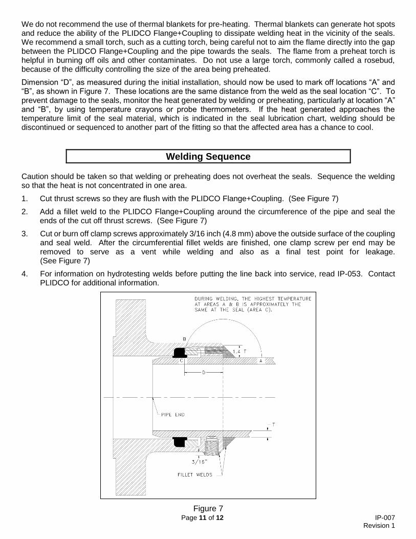
Dimension “D”, as measured during the initial installation, should now be used to mark off locations “A” and “B”, as shown in Figure 7. These locations are the same distance from the weld as the seal location “C”. To prevent damage to the seals, monitor the heat generated by welding or preheating, particularly at location “A” and “B”, by using temperature crayons or probe thermometers. If the heat generated approaches the temperature limit of the seal material, which is indicated in the seal lubrication chart, welding should be discontinued or sequenced to another part of the fitting so that the affected area has a chance to cool.
Welding Sequence
Caution should be taken so that welding or preheating does not overheat the seals. Sequence the welding so that the heat is not concentrated in one area.
1. Cut thrust screws so they are flush with the PLIDCO Flange+Coupling. (See Figure 7)
2. Add a fillet weld to the PLIDCO Flange+Coupling around the circumference of the pipe and seal the ends of the cut off thrust screws. (See Figure 7)
3. Cut or burn off clamp screws approximately 3/16 inch (4.8 mm) above the outside surface of the coupling and seal weld. After the circumferential fillet welds are finished, one clamp screw per end may be removed to serve as a vent while welding and also as a final test point for leakage. (See Figure 7)
4. For information on hydrotesting welds before putting the line back into service, read IP-053. Contact PLIDCO for additional information.
Figure 7
Page 12 of 12 IP-007 Revision 1
Storage Instructions
PLIDCO Flange+Couplings should be stored in a dry environment to prevent the unpainted surfaces from rusting. Storage temperatures should not exceed 120ºF (50ºC). Cover with a tarp made of dark polyethylene, box, etc. to keep the direct sunlight from the seals. It is best to exclude contamination, light, ozone, and radiation. Improperly stored PLIDCO Flange+Coupling can cause the seal material to become cracked and brittle and lose its ability to seal.
Traceability
PLIDCO Flange+Couplings, as with most PLIDCO products, have a unique serial number by which the fitting body material is fully traceable. Additionally, all elastomer seals have a unique batch number by which the seal material is traceable.
Recommended Inspection Schedule
1. After the pipeline is re-pressurized and field tested (see Re-pressuring and Field Testing for precautions), the torque values should be checked again 4 hours after installation. Then, the torque values should be checked again 24 hours after that.
2. It is recommended that torque striping be applied from the threads of all the screws to the body of the PLIDCO Flange+Coupling so that any loosening of the screws can be visually seen during an inspection.
3. 6 months after installation, it is recommended that a visual inspection occurs that checks for visible signs of leakage, bolt/nut loosening, and general wear or corrosion.
4. After the 6-month inspection, a yearly visual inspection is recommended that checks for visible signs of leakage, bolt/nut loosening, and general wear or corrosion.
1
The Pipe Line Development Company 870 Canterbury Road Westlake, Ohio 44145
Phone: (440) 871-5700 Fax: (440) 871-9577 Toll Free: 1-800-848-3333
www.plidco.com E-mail: [email protected]
FLANGE + ®PLIDCO הוראות התקנה
אות ההתקנה המקוריות בשפה האנגלית המצורפותמסמך זה הינו תרגום של הור לכל אביזר חדש. המסמך הקובע הוא המסמך המקורי בשפה האנגלית ,במקרה של אי התאמה בתרגום .פי העדכון האחרון שלועל
!! אזהרה !!
שימוש או בחירה לא נכונה במוצר זה יכולים לגרום לפיצוץ, אש, מוות, פציעה, .נזקי רכוש ו/או נזק לסביבה
קרא בעיון
האחראי להתקנה חייב להכיר את ההוראות הללו ולוודא שהן מועברות מנהלה לכל העובדים העוסקים בהתקנה.
עד אשר כל ההיבטים Plidco+Flangeאין להשתמש או לבחור באביזר הוראות התקנה אלה. קריאה והבנה שללאחר ו ם נבדקו יסודיתשל היישו נעשה מאמץ כדי להבטיח אריזה בטוחה למוצר זה טרם המשלוח, בדוק שלא קרה כל נזק במהלך ההובלה. הם באשר לשימוש באביזר זהאם יש לך אילו שאלות או אם נתקלת בקשיים כלש אנא פנה ל:
PLIDCO “DEPARTMENT 100” at 440-871-5700 toll free U.S. & Canada 800-848-3333
רשימות תיוג לבטיחות
ויישם בזהירות את הוראות ההתקנה.קרא הנוגעים ליישום. שמור על מדיניות הבטיחות של החברה שלך ועל כל הקודים והסטנדרטים
של במידה ונעשה שינוי במוצרPLIDCO החלפת אטמים על ידי גורם כולל כל שהיא צורה ב או חברה שקבלה הסמכה להחלפת PLIDCOשאינו מחלקת ההנדסה והייצור של חברת
PLIDCOאו אדם שקיבל הסמכה מחברת PLIDCOאטמים מחברת האחריות למוצר מסתיימת.אזי
מוצרים שנעשה בהם שינוי מאבדים את יתרון יכולת מעקב החומר, מסמכי ביקורת איכות .PLIDCOוניסיון העבודה של חברת
.בבארה" PLIDCOהערה: ניתן לבצע אימון ומבחני הסמכה למפעילים בתשלום בחברת
IP007 REV1
2
.וודא שחומר מבנה האטם מתאים ליישום שלהעמידות הכימית יג מורשה במידה ויש שאלות לגבי צאו לנ PLIDCOהתקשר לחברת
.ת העבודהפרטורלנוזל אשר בצינור ולטמ האטמים
ובעת ההתקנה, המתקינים חייבים להיות מצוידים להתקנה בעת ההכנות נעלי בטיחות.ב( ו+ Z87במשקפי מגן )תקן
סוג החיבור אשר אביזרקבע אתPlidco Flange + Coupling אמור לחבר : .מעוגן או לא מעוגן
תגית העל כרשום המותרהמרבי לחץהוקבע את נתוני בהמשך ' ב-א' וסעיפים קרא אביזר. מחוברת למתכתית הה ,סדרתי של האביזרהמספר המוטבעים על התגית הערה:
ולחץ מרבי מותר במצב "מעוגן" ובמצב "לא מעוגן". מרבית טורהטמפר תגית.העל רשומים הוהטמפרטורה אין לעבור את הלחץ
Pipe Not Anchored -א'. צינור לא מעוגן
נחשב במצב "לא מעוגן" Coupling Plidco Flange +Couplingאביזר , ובורגי הידוק האטמים ואינו מרותך לצינור רק באמצעות בורגי חביקה לצינוראם הוא מחובר הצינור ואת כוחות המשיכה הנוצרים בו. ללא שום אמצעי המגביל את תנועת או שהוא מותקן
Anchored Pipe -ב'. צינור מעוגן נחשב במצב "מעוגן" אם הוא מרותך לצינור Plidco Flange +Couplingאביזר או שהוא מותקן עם אמצעי המגביל את תנועת הצינור ואת כוחות המשיכה הנוצרים בו. או ע"י טכניקה מוכחת אחרת ע"י הלקוח. Plidco Clamp+Ringאביזר שימוש בע"י כגון
אביזרסך כל כוחות המשיכה המותרים עבורPlidco + Flange החלקת האביזר החוצה במצב לא מעוגן נקבעים על ידי יכולת בורגי החביקה להתנגד ל
.מאחיזתו בצינור יחידות לחץ על פי הנוסחה הבאה:בהינו הנתון של כוח זה
גרום לאביזר להחליקיכל צירוף של כוחות מעבר למגבלת האביזר במצב לא מעוגן
החוצה מאחיזתו בצינור. :כגוןלנבוע מכל מיני סיבות כוחות אלה יכולים
מאמצי התפשטות תרמית, מכתוצאה כוחותמעבר למותר במצב לא מעוגן, בצינור לחץ עבודה יפה, עומס גרביטציוני עקב תמיכת קטע ארוך של צינור,מאמצי כפ
תזוזות קרקע, זרמי ים, רעידות אדמה, ויברציות, גל הלם הגורם לשיאי לחץ עקב חידוש הזרמה וכו'. מהירה בצינור
אינם מוגבלים לסיבות הנ"ל ויכולות להיות סיבות נוספות. כוחות אלה
צריכים להילקח בחשבון ע"י הלקוח.נור אשר מעבר ללחץ העבודה בציכוחות נוספים שאינו יכול להיות מרוסן ע"י הלקוח באמצעות טכניקה מוכחת , ,אם קיים כוח כלשהוא
.Plidco Clamp+Ringבאביזר הפתרון הוא להשתמש אזי
ANSI B16.47או ANSI B16.5האוגנים מגביל את הכוחות הציריים, על פי תקן העבודה והכוחות לא יעברו את המגבלות של האוגנים.לחצי
3
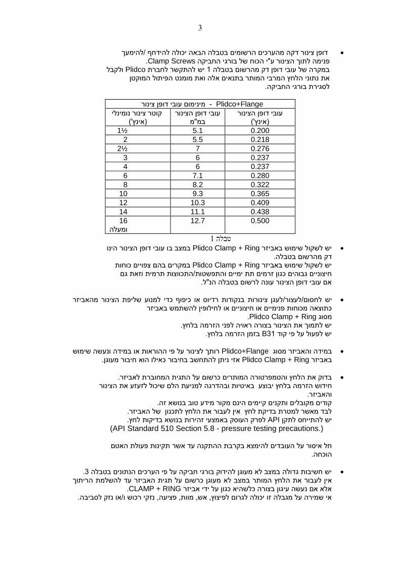
יכולה להידחף /להימעך הבאה טבלה הרשומים בדופן צינור דקה מהערכים .Clamp Screwsשל בורגי החביקה ע"י הכוחוך הצינור לתפנימה ולקבל Plidcoיש להתקשר לחברת 1 טבלההרשום במדק במקרה של עובי דופן הפיתול המוקטן מומנט הלחץ המרבי המותר בתנאים אלה ואת נתוני את לסגירת בורגי החביקה.
ימום עובי דופן צינור מינ - Plidco+Flange
קוטר צינור נומינלי )אינץ'(
עובי דופן הצינור במ"מ
עובי דופן הצינור )אינץ'(
1½ 5.1 0.200
2 5.5 0.218
2½ 7 0.276
3 6 0.237
4 6 0.237
6 7.1 0.280
8 8.2 0.322
10 9.3 0.365
12 10.3 0.409
14 11.1 0.438
16 ומעלה
12.7 0.500
1טבלה
יזר יש לשקול שימוש באבPlidco Clamp + Ring במצב בו עובי דופן הצינור הינו דק מהרשום בטבלה.
במקרים בהם צפויים כוחות Plidco Clamp + Ringיש לשקול שימוש באביזר וזאת גם התפשטות/התכווצות תרמיתו כגון זרמים תת ימיים חיצוניים גבוהים "ל.לרשום בטבלה הנ אם עובי דופן הצינור עונה
שליפת הצינור מהאביזר בנקודות רדיוס או כיפוף כדי למנוע צינורות חסום/לעצור/לעגן יש ל כתוצאה מכוחות פנימיים או חיצוניים או לחילופין להשתמש באביזר
.Plidco Clamp + Ringמסוג יש לתמוך את הצינור בצורה ראויה לפני הזרמה בלחץ.
.בלחץ הבזמן הזרמ 31Bיש לפעול על פי קוד
מסוגבמידה והאביזר Plidco+Flangeעל פי ההוראות או במידה ונעשה שימוש רותך לצינור חיבור מעוגן.אילו הוא כ אזי ניתן להתחשב בחיבור Plidco Clamp + Ring באביזר
.בדוק את הלחץ והטמפרטורה המותרים כרשום על התגית המחוברת לאביזר למניעת הלם שיכול לזעזע את הצינורהדרגה וב בוצע באיטיותיחידוש הזרמה בלחץ
והאביזר. קודים מקובלים ותקנים קיימים הינם מקור מידע טוב בנושא זה.
לבד מאשר למטרת בדיקת לחץ אין לעבור את הלחץ לתכנון של האביזר. נושא בדיקות לחץ.עי זהירות באמצלפרק העוסק ב APIלתקן יש להתייחס
(API Standard 510 Section 5.8 - pressure testing precautions.)
םבת ההתקנה עד אשר תקינות פעולת האטחל איסור על העובדים להימצא בקר הוכחה.
3יש חשיבות גדולה במצב לא מעוגן להידוק בורגי חביקה על פי הערכים הנתונים בטבלה. בור את הלחץ המותר במצב לא מעוגן כרשום על תגית האביזר עד להשלמת הריתוך אין לע
.CLAMP + RINGאלא אם נעשה עיגון בצורה כלשהיא כגון על ידי אביזר אי שמירה על מגבלה זו יכולה לגרום לפיצוץ, אש, מוות, פציעה, נזקי רכוש ו/או נזק לסביבה.
4
הכנת הצנרת
ר באזור המיועד להתקנה מציפוי חיצוני של הצינור, יש לנקות את שטח פני הצינו .1 למניעת בלאי על האטמים.ולשמן את פני השטח משקעים וחלודה גרדים,מ
רצוי להגיע למצב של פני שטח כמעט "לבנים", רמת הניקוי המועדפת הינה .SSPC-SP10 / NACE No.2על פי
ככל שפני הצינור נקיים וחלקים יותר האטימה תהיה טובה יותר.
± 1/32מ"מ = " ± 0.8האטמים יכולים לספוג טולרנס של פני השטח עד .2 בליטות ריתוך יש לשייף/להחליק עד לפני שטח הצינור.
הצינור הינו כדלקמן:חיצוני של טולרנס קוטר .3
± 1%כולל : 6לצנרת עד קוטר " 1/8- (mm 3.2)+( , " mm 1.6+ )1/16: "14ועד " 6לצנרת מקוטר "
( ± mm 4) ± 5/32ומעלה: " 14טר "לצנרת מקו
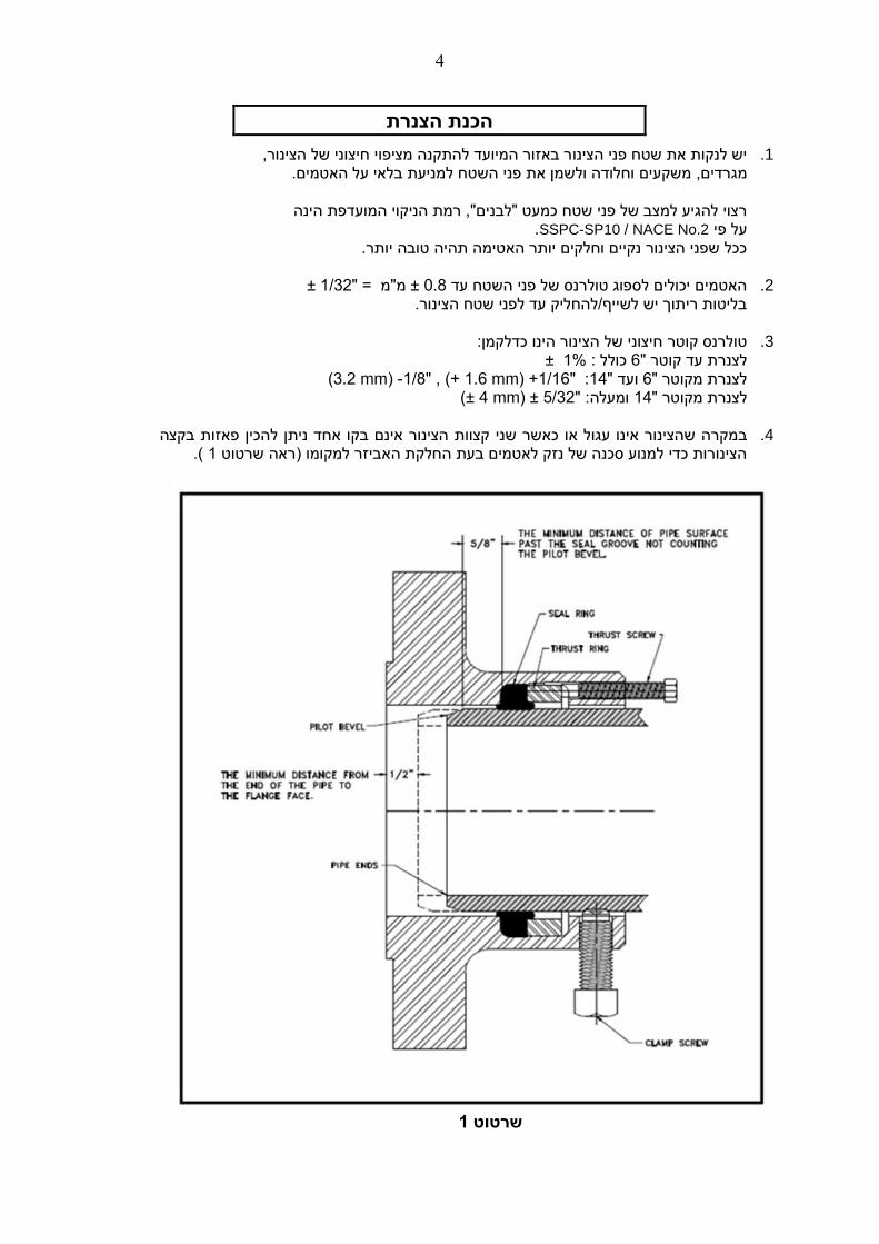
אינם בקו אחד ניתן להכין פאזות בקצה הצינור שני קצוות כאשר מקרה שהצינור אינו עגול או ב .4 (. 1ראה שרטוט ) הצינורות כדי למנוע סכנה של נזק לאטמים בעת החלקת האביזר למקומו
1שרטוט
5
תקנהה
.זהירותבחוסר האטמים עלולים להינזק עקב טיפול
אסור שאמצעי הרמה כגון שרשרות, כבלים או מזלג הרמה יהיו במגע עם האטמים. גרום לנזק לאטמים או להוצאתם מהחריצים בהם מותקנים.עלול לטיפול לא נכון
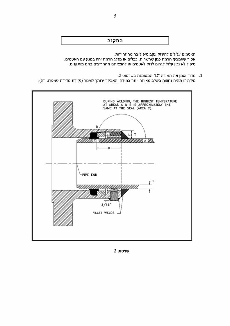
.2" המסומנת בשרטוט Dמדוד וסמן את המידה " .1 .טמפרטורה( נקודת מדידת(ר בשלב מאוחר יותר במידה והאביזר ירותך לצינוצה נחומידה זו תהיה
2רטוט ש
6
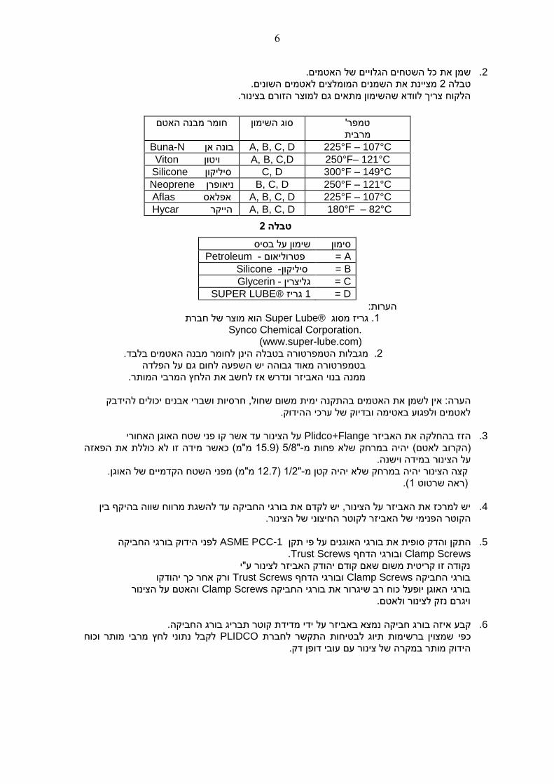
.מיםמן את כל השטחים הגלויים של האטש .2 השמנים המומלצים לאטמים השונים.מציינת את 2טבלה
הלקוח צריך לוודא שהשימון מתאים גם למוצר הזורם בצינור.
וןסוג השימ חומר מבנה האטם טמפר' מרבית
Buna-N A, B, C, D 225°F – 107°C בונה אן
Viton A, B, C,D 250°F– 121°C ויטון
Silicone סיליקון C, D 300°F – 149°C
Neoprene ניאופרן B, C, D 250°F – 121°C
Aflas A, B, C, D 225°F – 107°C אפלאס
Hycar הייקר A, B, C, D 180°F – 82°C
2 טבלה
סימון שימון על בסיס
Petroleum A = -פטרוליאום
Silicone סיליקון- = B
Glycerin גליצרין- = C
SUPER LUBE® גריז 1 = D
הערות: הוא מוצר של חברת ®Super Lube. גריז מסוג 1
Synco Chemical Corporation. (www.super-lube.com)
.בלבד האטמיםמבנה הינן לחומר בטבלה טורה. מגבלות הטמפר2 גם על הפלדהחום שפעה ליש ה המאוד גבוהטורה בטמפר
ממנה בנוי האביזר ונדרש אז לחשב את הלחץ המרבי המותר.
חול, חרסיות ושברי אבנים יכולים להידבקמשום ש הערה: אין לשמן את האטמים בהתקנה ימית לאטמים ולפגוע באטימה ובדיוק של ערכי ההידוק.
קו פני שטח האוגן האחוריעד אשר על הצינור Plidco+Flangeאת האביזר זז בהחלקה ה .3
מ"מ( כאשר מידה זו לא כוללת את הפאזה 15.9) 5/8"-יהיה במרחק שלא פחות מ( הקרוב לאטם) ל הצינור במידה וישנה.ע מ"מ( מפני השטח הקדמיים של האוגן. 12.7) 1/2"-קצה הצינור יהיה במרחק שלא יהיה קטן מ (.1)ראה שרטוט
יש למרכז את האביזר על הצינור, יש לקדם את בורגי החביקה עד להשגת מרווח שווה בהיקף בין .4 וני של הצינור.צהקוטר הפנימי של האביזר לקוטר החי
חביקה הלפני הידוק בורגי ASME PCC-1והדק סופית את בורגי האוגנים על פי תקן התקן .5
Clamp Screws ובורגי הדחףTrust Screws. נקודה זו קריטית משום שאם קודם יהודק האביזר לצינור ע"י ורק אחר כך יהודקו Trust Screwsובורגי הדחף Clamp Screwsבורגי החביקה והאטם על הצינור Clamp Screwsבורגי האוגן יופעל כוח רב שיגרור את בורגי החביקה ויגרם נזק לצינור ולאטם.
.בורג החביקהתבריג קוטר ידת מדאיזה בורג חביקה נמצא באביזר על ידי קבע .6
לקבל נתוני לחץ מרבי מותר וכוח PLIDCOשמצוין ברשימות תיוג לבטיחות התקשר לחברת כפי הידוק מותר במקרה של צינור עם עובי דופן דק.
7
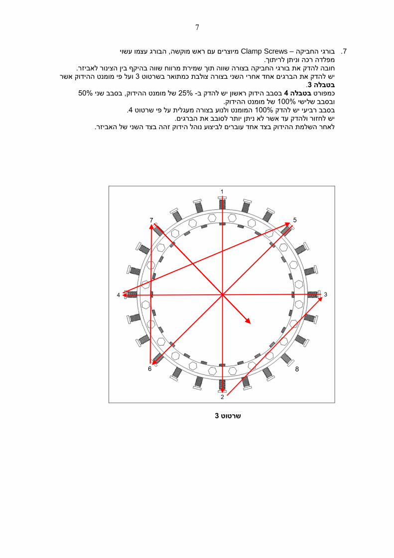
י ובורג עצמו עשהמיוצרים עם ראש מוקשה, Clamp Screws –בורגי החביקה .7 מפלדה רכה וניתן לריתוך.
את בורגי החביקה בצורה שווה תוך שמירת מרווח שווה בהיקף בין הצינור לאביזר. להדקחובה הידוק אשר המומנט על פי ו 3בשרטוט בצורה צולבת כמתואר אחד אחרי השני יש להדק את הברגים
.3בטבלה 50%של מומנט ההידוק, בסבב שני 25% -בסבב הידוק ראשון יש להדק ב 4בטבלה כמפורט
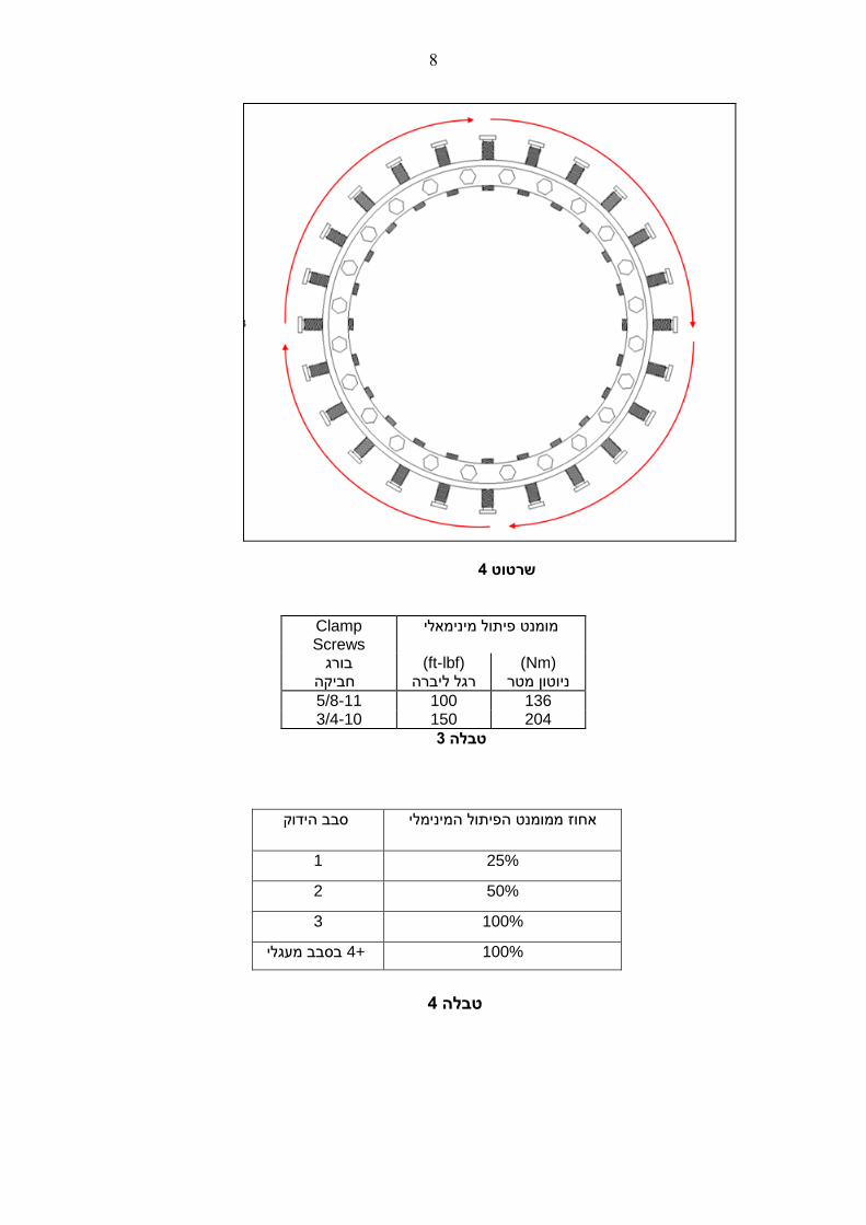
של מומנט ההידוק. 100%ובסבב שלישי .4המומנט ולנוע בצורה מעגלית על פי שרטוט 100%ביעי יש להדק בסבב ר
יש לחזור ולהדק עד אשר לא ניתן יותר לסובב את הברגים. לאחר השלמת ההידוק בצד אחד עוברים לביצוע נוהל הידוק זהה בצד השני של האביזר.
3שרטוט
8
4שרטוט
Clamp Screws
מינימאליפיתול מומנט
בורג חביקה
(ft-lbf) ליברה רגל
(Nm) טון מטרוני
5/8-11 100 136 3/4-10 150 204
3טבלה
4טבלה
אחוז ממומנט הפיתול המינימלי סבב הידוק
1 25%
2 50%
3 100%
100% מעגליבסבב +4
9
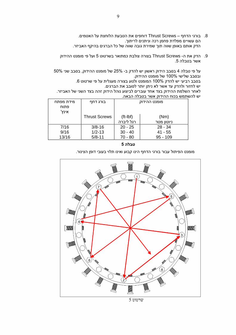
האטמים.לוחצת על את הטבעת הדוחפים Thrust Screws –ורגי הדחף ב .8
ם מפלדת פחמן רכה וניתנים לריתוך.הם עשויי הברגים בהיקף האביזר.כל הדק אותם באופן שווה תוך שמירת גובה שווה של
ועל פי מומנט ההידוק 5בצורה צולבת כמתואר בשרטוט Thrust Screws -ה הדק את .9
.5אשר בטבלה
50%של מומנט ההידוק, בסבב שני 25% -בסבב הידוק ראשון יש להדק ב 4על פי טבלה של מומנט ההידוק. 100%ובסבב שלישי
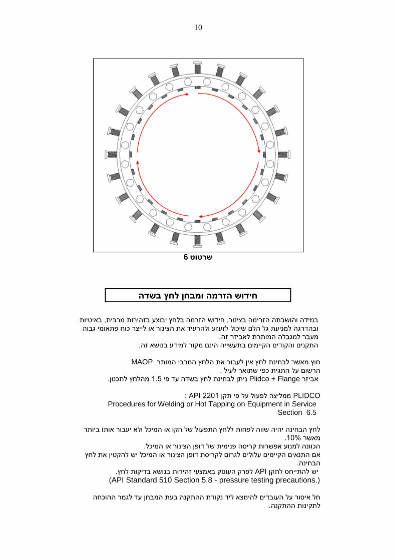
.6המומנט ולנוע בצורה מעגלית על פי שרטוט 100%בסבב רביעי יש להדק יש לחזור ולהדק עד אשר לא ניתן יותר לסובב את הברגים.
רים לביצוע נוהל הידוק זהה בצד השני של האביזר.לאחר השלמת ההידוק בצד אחד עוב אשר בטבלה הבאה.הידוק יש להשתמש בכוח ה
מידת מפתח פתוח אינץ'
ההידוק מומנט בורג דחף
Thrust Screws (ft-lbf) ליברה רגל
(Nm) ניוטון מטר
7/16 3/8-16 20 - 25 28 - 34 9/16 1/2-13 30 - 40 41 - 55
13/16 5/8-11 70 - 80 95 - 109
5טבלה
קבוע ואינו תלוי בעובי דופן הצינור.הינו הפיתול עבור בורגי הדחף מומנט
5שרטוט
10
6שרטוט
שדהלחץ בחידוש הזרמה ומבחן
באיטיות במידה והושבתה הזרימה בצינור, חידוש הזרמה בלחץ יבוצע בזהירות מרבית, או לייצר כוח פתאומי גבוה את הצינור ולהרעיד לם שיכול לזעזע גל הובהדרגה למניעת . מעבר למגבלה המותרת לאביזר זה ר למידע בנושא זה. התקנים והקודים הקיימים בתעשייה הינם מקו
MAOPחוץ מאשר לבחינת לחץ אין לעבור את הלחץ המרבי המותר .הרשום על התגית כפי שתואר לעיל לתכנון.מהלחץ 1.5ניתן לבחינת לחץ בשדה עד פי Plidco + Flange אביזר PLIDCO 2201ממליצה לפעול על פי תקן API : Procedures for Welding or Hot Tapping on Equipment in Service
Section 6.5
לחץ הבחינה יהיה שווה לפחות ללחץ התפעול של הקו או המיכל ולא יעבור אותו ביותר .10%מאשר הכוונה למנוע אפשרות קריסה פנימית של דופן הצינור או המיכל. ם לגרום לקריסת דופן הצינור או המיכל יש להקטין את לחץ אם התנאים הקיימים עלולי הבחינה. לפרק העוסק באמצעי זהירות בנושא בדיקות לחץ. APIלתקן יש להתייחס
(API Standard 510 Section 5.8 - pressure testing precautions.)
בחן עד לגמר ההוכחה חל איסור על העובדים להימצא ליד נקודת ההתקנה בעת המ .לתקינות ההתקנה
11
הוראות ריתוך בשדה
רריתוך לטובת האטימה בלחץ של אביזנדרש לא Plidco+Flange
אשר תקנים תלוי בדרישות הלקוח, בהנושא של ריתוך .ובעומסים הציריים שעל האביזר לשאת בשימוש
!!אזהרה !!
יכולה לגרום לפיצוץ, אש, ריתוך ההוראות אי שמירת מוות, פציעה ונזק לרכוש ו/או לסביבה
במסמך נם ניתניםאי FLANGE+ PLIDCO כל ההנחיות וההיבטים הקשורים לריתוך אביזר
.PLIDCOעל ידי חברת זה על כל לקוח לפנות לתקנים הבאים: בנושאי ריתוך
ASME PCC-2, API 1104 Appendix B, ASME Section IX, PRCI L52047, PRCI Hot Tap® Model, או למידע תעשייתי אחר הנוגע לריתוך ולקבוע את נוהלי הריתוך
.תכנון הריתוךשלב ב .Welding Considerations : בשם IP-019 סימוכין PLIDCOראה מסמך למידע נוסף
יםהמותר)על פי התנאים מלא ותחת זרימהיהיה הצינור בזמן ריתוך מומלץ ש
.(למצב "מעוגן" או "לא מעוגן"
,API 1104ריתוך חייבים להיות מאושרים בהתאם לתקן הרתכים ושיטות ה “Welding of Pipelines and Related Facilities”, Appendix B, In-Service Welding.
( בגלל עמידותן 18XX– E) SMAWאו GMAWכגון ודות דלות מימןבאלקטרמאוד להשתמש מומלץ
ובפני פריכות מימנית. לספיחת לחותהגבוהה יבשות בצורה מוחלטת. להיות חייבות SMAW (Shielded metal arc welding)אלקטרודות
לנוהל ההסמכה משתנים החיוניים בכל החשוב מאוד שנוהלי הריתוך בשדה יהיו עוקבים
שבוצעו בנוהל ההסמכה. םהמכאנייתייצג את המבחנים שאיכות הריתוך בשדה כך
ל גדול מזה ש/( שווהTensile Strengthהשתמש בחומרי ריתוך )אלקטרודות( עם חוזק למתיחה ) הצינור.
( בהיקף.Fillet מילאת = ) המילאת יש לפקח בזהירות על הצורה והגודל של ריתוך ולתת יציבות אורכית.לצינור את החיבור הריתוך נדרש כדי לעגן
מעובי דופן הצינור. 1.4)פילה( יהיה לפחות מילאת גובה ה פגם בריתוך(. ללא 100%-)כלומר שהריתוך תקין ב 1מצב זה מניח מקדם יעילות חיבור
בהתבסס על רמת ביקורת ( JOINT EFFICIENCY)ניתן לבחור במקדם יעילות חיבור שונה האיכות ומדיניות הריתוך של החברה שלך.
כיםיש לשאוף לריתוך פילה קעור הנושק לשני הצדדים המרותכים, יש להימנע מחריצים וחת(Undercut).
ו גבוהה יותר מפני כשל עייפות החומר.ככל שהריתוך חלק ורציף העמידות של בולט כלפי מעלה הרבה מעבר לנדרש הגורםהינה ריתוך קמור הגרועה ביותר הצורה האפשרית
לריכוז מאמצים מקומי.
יגרום לנזילה, פריצה או פיצוץ עם ש חומרמהיר של הריתוך בצורה לא מתאימה יוליך לכשל עייפות חמורות. תוצאות
12
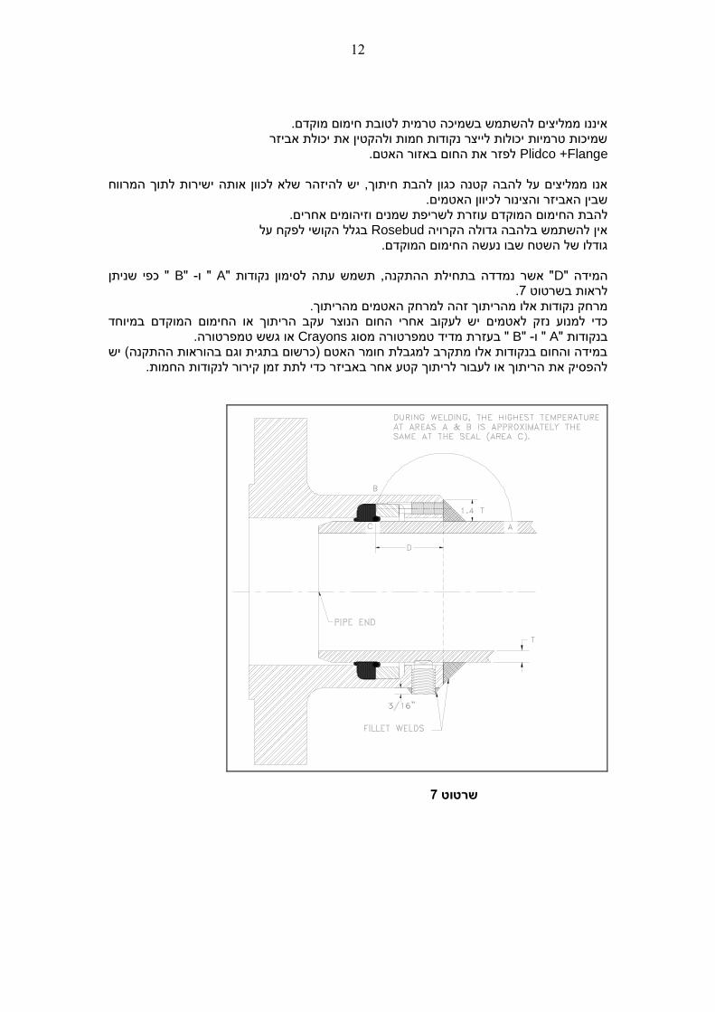
איננו ממליצים להשתמש בשמיכה טרמית לטובת חימום מוקדם. שמיכות טרמיות יכולות לייצר נקודות חמות ולהקטין את יכולת אביזר
Plidco +Flange לפזר את החום באזור האטם.
ישירות לתוך המרווח שלא לכוון אותה רלהיזהוך, יש אנו ממליצים על להבה קטנה כגון להבת חית שבין האביזר והצינור לכיוון האטמים.
ום המוקדם עוזרת לשריפת שמנים וזיהומים אחרים.להבת החימ בגלל הקושי לפקח על Rosebudאין להשתמש בלהבה גדולה הקרויה
גודלו של השטח שבו נעשה החימום המוקדם.
ן " כפי שנית B" -" ו A" אשר נמדדה בתחילת ההתקנה, תשמש עתה לסימון נקודות "Dהמידה " .7לראות בשרטוט
הריתוך זהה למרחק האטמים מהריתוך.מרחק נקודות אלו מהמוקדם במיוחד או החימוםהריתוך אחרי החום הנוצר עקב כדי למנוע נזק לאטמים יש לעקוב
.טורהגשש טמפראו Crayonsמסוג טורהטמפרמדיד " בעזרת B" -" ו Aבנקודות "יש ההתקנה( במידה והחום בנקודות אלו מתקרב למגבלת חומר האטם )כרשום בתגית וגם בהוראות
קטע אחר באביזר כדי לתת זמן קירור לנקודות החמות. ריתוך להפסיק את הריתוך או לעבור ל
7 שרטוט
13
סדר הריתוך
לא תגרום לחימום יתר של או החימום המוקדם הריתוך טורתיש לעקוב בזהירות ולוודא שטמפר
לא יתרכז באזור אחד.הריתוך יעשה כך שהחום האטמים.
. 7ראה שרטוט בקו ישר עם גוף האביזר Thrust Screws –ף בורגי דחחתוך את .1
ריתוך כולל הצינור האביזר סביב היקף ב( Fillet)המילאת עם ריתוך התחל .2 .( 7)ראה שרטוט לאיטום בורגי הדחףסביב
מ"מ( 4.8) 3/16ה "בגוב Clamp Screws –חתוך את בורגי החביקה .3
.ם ורתך אותם לאיטו האביזר מעל לפני שטח ריתוך ההיקפי יש להסיר בורג חביקה אחד בכל צד כדי שהחלל שלו הבגמר
ישמש לניקוז הגזים בזמן ריתוך שאר בורגי החביקה. (. 7)ראה שרטוט אם יש דרישה כזאת נזילהת כנקודה לבדיקחלל זה יכול גם לשמש
סמךלמידע על אופציית בדיקת הריתוכים בלחץ לפני הכנסת הקו לשימוש קרא את מ .4
IP-053 של חברתPLIDCO (CLAMP SCREW TEST PORT ) לקבלת מידע נוסף. PLIDCOאו התקשר לחברת
הוראות אחסנה
כדי למנוע חלודה של השטחים הגלויים. היבשסביבה באחסן יש ל Plidco+Flangeאביזרי מעלות צלסיוס. 50האחסנה לא תעלה על טורת טמפר
יש לכסות את האביזר בפוליאתילן כהה כדי למנוע קרני שמש מלהגיע לאטמים. מנוע חשמלי( וזיהום במקום האחסנה.מוע המצאות אור, קרינה, אוזון )יש למנ
אחסנה לקויה יכולה לגרום לסדקים באטמים, הפיכתם לשבירים ואיבוד כושר האטימה שלהם.
מעקב
מספר סדרתי יםנושא Plidcoמרבית מוצרי כמו Plidco+Flange יאביזר
המאפשר מעקב מלא. בקרת איכות הנשמרת בארכיון החברה וניתןלכל אביזר יש חבילת מסמכי
לדעת מתוכה את יצרן חומרי הגלם, הרכב המתכת, בדיקות איכות שעבר האביזר וכו'.
שמאפשר לעקוב אחרי אותה מנה.לכל אטם יש מספר מנה
לוח זמנים מומלץ לביקורת פיקוח
לאחר חידוש הזרימה בקו ולאחר ביצוע מבחן לחץ )ראה . 1API Standard 510 Section 5.8 - pressure testing precautions
שעות מסיום ההתקנה. 24שעות ואחרי 4מים אחרי יש לחזור ולבצע סבב הידוק נוסף לאו , במידה והאום ישתחרר/יסתובב ניתן של כל אום חביקה מומלץ לצבוע קווי סימון למיקום .2
יהיה לראות זאת בעין על פי הסימון שזז. חודשים אחרי ההתקנה מומלץ לבצע בדיקת ראייה ולבחון שאין סימני נזילה, שהאומים לא 6 .3
מקומם המקורי ולבצע בחינה כללית לקורוזיה ובלאי.הסתובבו מ מומלץ בהמשך לבצע בדיקה כנ"ל אחת לשנה. .4
*********************************