Embed Size (px)
Citation preview

International Journal of Scientific & Engineering Research, Volume 5, Issue 6, June-2014 1366 ISSN 2229-5518
IJSER © 2014 http://www.ijser.org
STUDY OF NATURAL CONVECTION HEAT TRANSFER ON HORIZONTAL, INCLINED AND VERTICAL HEATED PLATE BY V-FIN ARRAY
Rameshwar B. Hagote, Sachin K. Dahake.
Abstract— Extended surfaces, commonly known as fins are, used to enhance convective heat transfer in a wide range of engineering applications, and offer an economical and trouble free solution in many situations demanding natural convection heat transfer. Fin arrays on horizontal, inclined and vertical surfaces are used in variety of engineering applications to dissipate heat to the surroundings. Studies of heat transfer and fluid flow associated with such arrays are therefore of considerable engineering significance. The main controlling variables generally available to the designer are the orientation and the geometry of the fin arrays. An experimental work on natural convection adjacent to a vertical heated plate with a multiple V- type partition plates (fins) in ambient air surrounding is already done. Boundary layer development makes vertical fins inefficient in the heat transfer enhancement. As compared to conventional vertical fins, this V-type partition plate works not only as extended surface but also as flow turbulator. This V-type partition plate is compact and hence highly economical. The numerical analysis of this technique is done using Computational Fluid Dynamics (CFD) software, Ansys CFX , for natural convection adjacent to a vertical heated plate in ambient air surrounding. In numerical analysis angle of V-fin is further optimized for maximum average heat transfer coefficient. Attempts are made to validate the results obtained by using CFD analysis by experimentation. The experimental studies have been carried out on three geometric orientations viz., (a) Vertical base with V-fin array (vertical fin array) (b) Horizontal base with V-fin array (horizontal fin array), (c) Inclined base with V-fin array (inclined fin array).
Index Terms— V type fins, Flow turbulator, Base plate orientation, V-type partition plate, CFD analysis, numerical analysis.
—————————— ——————————
1 INTRODUCTION Fins are used to enhance convective heat transfer in a wide
range of engineering applications, and offer a practical means for achieving a large total heat transfer surface area without the use of an excessive amount of primary surface area. Fins are commonly applied for heat management in electrical ap-pliances such as computer power supplies or substation trans-formers. Other applications include Internal Combustion en-gine cooling, such as fins in a car radiator. It is important to predict the temperature distribution within the fin in order to choose the configuration that offers maximum effectiveness.
Natural convection heat transfer is often increased by pro-vision of rectangular fins on horizontal or vertical surfaces in many electronic applications, motors and transformers. The current trend in the electronic industry is miniaturization, making the overheating problem more acute due to the reduc-tion in surface area available for heat dissipation.
Thus heat transfer from fin arrays has been studied exten-sively, both analytically and experimentally.
2 REVIEW OF LITERATURE Sane etal.(2008) established a match between the experi-
mental results and the results obtained by using CFD software for a horizontal rectangular notched fin arrays dissipating heat by natural convection Both, the flow patterns as well as the trend of heat transfer coefficient are found to be within 5% range. It is observed that total heat flux as well as the heat transfer coefficient increases as the notch depth increases. As area removed from the fin is compensated at the air entry ends of the fin it provides chance to get greater amount of fresh cold air (getting sucked into the array through single chimney pattern) to come in contact with hot fin surface. As the air
moves inwards along chimney profile, it gets heated and tem-perature difference between the fin and entering air decreases. This area of fin (near its lengthwise centre) thus becomes rela-tively less useful for heat transfer. Now, when this area is re-moved and added at place where it is more useful for heat transfer, the heat transfer increases and so does the convective heat transfer coefficient. CFD analysis was completed for two cases viz (a) Unnotched fin Array and (b) Fin Array with Notch of 20 %and 40% area removed. This analysis reveals that the single chimney flow pattern is maintained for both the cases. Performance of notched array is better by up to 41.82%[1].
Wankhede(2008) developed an experimental setup to carry out the investigation on horizontal rectangular fin array with and without inverted notch under natural and forced convec-tions. The objective of the work was to determine the heat transfer characteristics experimentally, and further to find out the enhancement in heat transfer in the case of notched fin arrays over normal fin arrays, and analyzed the effect of dif-ferent parameters like length, height, spacing of fins on heat transfer coefficient (h). It is concluded that, the values of aver-age heat transfer coefficient ha increases as percentage of area removed increases near about 30 to 70% rise is achieved as compared to normal fin array. The value of base heat transfer coefficient (hb) increases as fin spacing decreases reaches its maximum, giving optimum spacing and again decreases. For very less fin spacing the values of both ha and hb are signifi-cantly less. The value of average Nusselt number (Nua) in-creases with increase in fin spacing. The value of base Nusselt number(Nub) increases as fin spacing decreases; it reaches to its maximum and again decreases[2].
Barhatte(2012) did the study on heat transfer rate through
IJSER

International Journal of Scientific & Engineering Research, Volume 5, Issue 6, June-2014 1367 ISSN 2229-5518
IJSER © 2014 http://www.ijser.org
different types of notches in the fin. He used different notch such as rectangular, circular, triangular and trapezoidal. He compare without notch and notch fin array by supplying dif-ferent heat inputs. The dimensions of fin were fixed. They concluded that more heat is transfer through triangular notch fin[3].
Kharche and Farkade(2012) used fin with notch and with-out notch of copper as a fin material on vertical heated plate for the experimental work. The shape of the notch was rectan-gular. They compared the effect of heat transfer coefficient for notch and without notch fins. From the experimental study it was found that the heat transfer rate in notched fins was more than the unnotched fins. The average heat transfer coefficient for without notched fin was 8.3887W/m2K and for 20% notched fins it was 9.8139W/m2K. Also the copper gives more heat transfer rate than aluminum plate. In order to dispose off the boundary layer restrictions and develop a compact high-performance heat transfer plate, some investigators have de-veloped horizontal partition plate and V - shaped plates[4].
Misumi and Kenzo (1990) have reported an experimental work on enhancement of natural convection heat transfer from vertical plate having a horizontal partition plate and V-plates in the water ambience. They found that the heat transfer in the downstream region of the partition plate is markedly en-hanced when the plate height exceeds certain critical values because of the inflow of the low temperature fluid into the separation region. For vertical plate with V-shaped fins, the heat transfer coefficient obtained was 40% higher than the conventional fins[5].
Edlabadkar etal.(2008) did experimental investigation on single V-type partition plate with different included angles, in air as ambience in the laminar air flow over a vertical base plate with length 0.3m, width 0.3m, and V shape fin (the fin limb length is 0.15m and width 0.05m) attached to it was nu-merically captured using Computational Fluid Dynamics (CFD) software of FLUENT with laminar viscous model. Computations were performed for the geometrical configura-tions with fin included angles 90°, 120° and 60°, for equal base and fin areas dissipating heat under natural convection condi-tion for temperature difference θ, varying from 30°C to 150°C. The results show that the 90° V fin gives least resistance to flow separation in the upstream region and most effective high heat transfer region in the downstream region of the base plate. It was observed that among the three V-type partition plates, the maximum increase in heat transfer enhancement is 12% for 90° V-partition plates as compared to vertical partition Plate and 15.27% as compared to horizontal partition plate[6].
Sable etal.(2010)investigated heat transfer enhancing tech-nique for natural convection adjacent to a vertical heated plate with a multiple V- type partition plates (fins) in ambient air surrounding. They concluded that as compared to conven-tional vertical fins, the V-type partition plates work not only as extended surface but also as flow turbulator. The tall vertical fin array restricts the heat transfer enhancement from tall ver-tical base plate. This is because of the boundary layer thicken-ing and subsequent interference developed over the height. The experiments were conducted with the width of the parti-tion plate (fin height) varying from 20mm to 38mm for a plane vertical plate, vertical plate with vertical fins, vertical plate
with V-fins with bottom spacing and vertical plate with differ-ent V-type fins. It is further observed that the base heat trans-fer coefficient (hb) of V-type fin array is better than all other configurations. The hb for plain plate is least among all. The V-type fin array better diminishes the stagnation high temper-ature fluid in upstream region of the plate. Thus in this inves-tigation work, a totally new heat transfer technique is found out to increase the rate of natural convection heat transfer on vertical heated plate. The V-type fin array can be seen as the combination of a horizontal and vertical partition plates. For the same surface areas, V-type partition plates gave better heat transfer performance than vertical rectangular fin array and V-fin with bottom spacing type array[7].
Aberra et al.(2012)studied numerically the stability of the natural convection boundary layer on an evenly heated verti-cal plate for a Boussinesq fluid with Prandtl numbers of Pr= 0.733 and 6.7, With Ra=1x1010,0<x<1.25 (giving the local Ray-leigh number 0 <Rax< 2.4 x10¹⁰. A Boussinesq fluid with Prandtl numbers of Pr= 0.733 (air) and 6.7 (water).The stability results have been compared with those obtained using the conventional parallel linear theory, and with experimental data. Good agreement has been obtained between the numeri-cal stability predictions, the parallel linear theory and the lim-ited experimental data. The closest correspondence was ob-tained for high Rax, high frequency and high Pr, where non-parallel effects are least important[8].
Tsujiet al.(2007)conducted an experimental study on heat transfer enhancement for a turbulent natural convection boundary layer in air along a vertical flat plate has been per-formed by inserting a long flat plate in the span wise direction (simple heat transfer promoter) and short flat plates aligned in the span wise direction (split heat transfer promoter) with clearances into the near-wall region of the boundary layer. For a simple heat transfer promoter, the heat transfer coefficients increase by a peak value of approximately 37% in the down-stream region of the promoter compared with those in the usual turbulent natural convection boundary layer. It is found from flow visualization and simultaneous measurements of the flow and thermal fields with hot- and cold-wires that such increase of heat transfer coefficients is mainly caused by the deflection of flows toward the outer region of the boundary layer and the invasion of low-temperature fluids from the out-er region to the near-wall region with large-scale vortex mo-tions riding out the promoter. It was concluded that heat transfer enhancement of the turbulent natural convection boundary layer can be substantially achieved in a wide area of the turbulent natural convection boundary layer by employing multiple column split heat transfer promoters. It may be ex-pected that the heat transfer enhancement in excess of approx-imately 40% can be accomplished by inserting such promot-ers[9].
In the literature review, the various investigations done on the topic of natural convection heat transfer from horizontal, vertical and inclined heated plate and its surface modifications along with various enhancement techniques for the heat trans-fer enhancement are seen. It was observed that some research-ers have varied fin parameters like length of fin, height of fin, spacing between the fins and found that as the length and height of fin increases the heat transfer coefficient increases.
IJSER

International Journal of Scientific & Engineering Research, Volume 5, Issue 6, June-2014 1368 ISSN 2229-5518
IJSER © 2014 http://www.ijser.org
But this increase in the heat transfer coefficient is up to a cer-tain limit. For maximum heat transfer coefficient optimum fin spacing is required. In the next part it is also seen that heat transfer coefficient depends upon orientation of base plate. It was also seen that by using electro hydro dynamic technique heat transfer coefficient can be increased. By using perfora-tions on the fin, natural convection heat transfer coefficient can be increased. Perforations may be equilateral, triangular and rectangular. It was found that as the number of perforations increases heat transfer coefficient increases. Some researchers have used notch of different shape on fin and found that notched fin performs better than fin with without notch. It was also found that as the depth of notch increases heat transfer coefficient increases but up to a certain limit. Instead of alumi-num, one of the researchers has used copper as a fin material and for the same he obtained better heat transfer coefficient. Few researchers have worked on V-fin. One of them used sin-gle V-fin with water ambience. Another used single V-fin with air ambience for computational work and found that V-fin gives more heat transfer coefficient than horizontal and verti-cal fin. It is due to the thickness of boundary layer which is more for horizontal fin and vertical fin as compared to V-fin. It was also found that V-fin acts as a flow turbulator. After this one of the researchers have used multiple V-fins for his exper-imental work and observed that multiple V-fins on base plate give more heat transfer coefficient than horizontal and vertical rectangular fin. So it is decided to work on V-fin array for computational and experimental work, as V-fin gives greater natural convection heat transfer coefficient.
3 V-FIN ANALYSIS USING ANSYS CFX The required models for computational analysis are first
made in PRO-E software and then imported in the CFX-Pre Processor. The aim of the project is to find the optimum in-cluded angle for V-fins. Therefore various models are created with included angles 0°, 30°, 60°, 90°, 120°, 180°. These models are then analyzed in CFX. The computational analysis in this project is carried out with the help of the software ANSYS 14.5. The vertical pitches for these models are first determined and then are used in PRO-E software.
3.1 calculations for v fin parameters
While selecting a heat sink a question that often arises is whether to select closely packed fins or widely spaced fins for a given base area (Figure 4.1). A heat sink with closely packed fins will have greater surface area for heat transfer but a smaller heat transfer coefficient because of the extra resistance the additional fins introduce to fluid flow through the inter-fin passages. A heat sink with widely spaced fins, on the other hand, will have a higher heat transfer coefficient but a smaller surface area. Therefore, there must be an optimum spacing that maximizes the natural convection heat transfer from the heat sink for a given base area WL, where W and L are the width and height of the base of the heat sink, respectively, as shown in Figure 4.2. S is the optimum fin spacing and t is the thickness of the fins.
Fig-1:Finned Surface Oriented Vertically
To calculate the optimum fin spacing, let us consider the model taken by sable et al. for vertical fins as in Fig-1. The model considered is of base plate 250mm x 250mm with verti-cal fins having fin height 20mm and fin thickness 3mm. The heater input is 100W. The surface temperature is Ts = 120°and Temperature of air, Ta = 27°
3.2 V-fin model creations in Pro/E
The various types of fins with proper orientation and spac-ing can be modeled on different CAD software available in the market. These softwares are compatible with the softwares for computational fluid dynamics. For the current modeling, Pro|E 5.0 has been used. The models so formed are along with the fluid domain where in the effects of the heat flow has to be analyzed. Pro|E is a solid modeling system with many ex-tended design and manufacturing applications. As a compre-hensive CAD/CAE/CAM system, covering many aspects of mechanical design, analysis and manufacturing. Pro|E repre-sents the leading edge of CAD/CAE/CAM technology. Pro|E was the industry's first successful rule-based constraint 3D CAD modeling system. Pro/E provides a complete set of de-sign, analysis and manufacturing capabilities on one, integral, scalable platform. These required capabilities include Solid Modeling, Surfacing, Rendering, Data Interoperability, Routed Systems Design, Simulation, Tolerance Analysis.
Fig-2: V-Fins Model
IJSER

International Journal of Scientific & Engineering Research, Volume 5, Issue 6, June-2014 1369 ISSN 2229-5518
IJSER © 2014 http://www.ijser.org
3.3 CFD analysis for V-fin Ansys software is capable of performing stress analysis,
thermal analysis, modal analysis, frequency response analysis, transient simulation. My requirement here is thermal analysis of the model. Finite element method of discretization is used. CFX is a commercial Computational Fluid Dynamics (CFD) program, used to simulate fluid flow in a variety of applica-tions. The ANSYS CFX product allows testing systems in a virtual environment. The scalable program has been applied to the simulation of water flowing past ship hulls, fins, gas turbine engines, aircraft aerodynamics, pumps, and fans. Ini-tially solid body and meshing for the geometrical modeling is done in ICEM. At the start in ICEM new working directory is created. Then geometry is imported from pro-e software which was in the form of Step/iges file. The file that opens, as above, is a surface model which does not have two surfaces in the front and back, as seen. Due to this, the fluid domain is still to be completely formed. The front and back faces are cre-ated by using create/modify surface as options. The next step is to create parts on the model as per convenience. The various parts are created for the fluid domain and aluminum domain.
Fig-3:Final blocking for Outer domain
Fig-4: Final Blocking for solid aluminum
Fig-5: Final Blocking for single V fin
In blocking initially it is required to give the premesh pa-rameters to define the mesh size and for this by selecting dif-ferent edges of the model, number of nodes are given. For the outer domain 60 numbers of nodes are assigned. Once we define the mesh size, premesh is generated as shown in Fig-ures.
Fig-6:Premesh for outer domain
Fig-7:Premesh for half aluminum domain
Fig-8:Premesh for single V fin
The quality of the mesh can be checked by selecting mesh
IJSER

International Journal of Scientific & Engineering Research, Volume 5, Issue 6, June-2014 1370 ISSN 2229-5518
IJSER © 2014 http://www.ijser.org
quality and keep the default parameters and select ok. A range of quality values appear on the screen, the minimum and low-est quality value being zero and the best, highest quality value being one. For this model minimum of quality is 0.66 and maximum is 1. The number of mesh element in each of the quality classes also appear in the dashboard below. The mesh quality is also verified by checking angle, aspect ratio etc. The value of angle should be more than 180 and less than 900.The angle for outer domain is around 400.The volume above zero is acceptable. For present geometry above mentioned values are obtained within the required range as shown in Figures.
Fig-9:Quality for outer domain
Fig-10:Angle for outer domain
To improve the mesh quality it is required to obtain the above mentioned values within the range. If the quality is still not good then, we have to improve the split, projections .This ICEM model is now complete and ready for pre-processing in CFX. Select the ‘output’ option in the tool chest and write in-put finally the save file. 3.3.1 Pre –Processing
Both the mesh solid and mesh fluid domains are now ready for pre-processing in CFX. Each of the models is individually called in the CFX pre file. Since the axes of both the models match, they do not have to be separately aligned in the CFX file.
The page has a tree flow on the right hand side which helps to follow a definite sequence of preprocessing. The main objec-tive of pre-processing is to set up the necessary boundary conditions. These conditions are actually the constraints under
which the solver has to determine the flow conditions. The actual ambience and experimentation can be carried out under a whole variety of different conditions and combinations. Therefore, defining boundary conditions is extremely critical in pre-processing. Even one minor change can lead to a set of totally different results than expected.
Fig-11:Fluid domain setting
The bottom most surface is the heater. Over heater there is a heater top side one (base plate) .The boundary specifications for the fluid domain are now complete. We have inserted an-other domain to accommodate the fluid boundary conditions.
Fig-12: Solid Domain setting
All the boundaries are thus defined and the model is now ready for processing in the CFX solver. The final model with the model tree flow appears as in the above picture. 3.3.2 Processing
After the pre-processing is complete and the run is defined, and the solver starts processing in the CFX solver manager. The number of iterations that are carried out depends on the convergence criteria. If the solution is converged before the total number of iterations, as specified, is complete, the solver stops and saves the processed data. If the solution does not get converged within the given number of iterations, we can give additional iterations to the solver till convergence is reached. When the iterations begin, the screen shows the variations in
IJSER
International Journal of Scientific & Engineering Research, Volume 5, Issue 6, June-2014 1371 ISSN 2229-5518
IJSER © 2014 http://www.ijser.org
velocity, momentum etc as the iterations proceed. These graphs give a general idea of how the system is stabilized and convergence is approached. Figure 13 indicates the solver fin-ished the run successfully and convergence of run.
Fig-13: Convergence of run
4. EXPERIMENTAL WORK The literature survey reveals that so far the study of natural
convection heat transfer using V-type fins was confined to water as ambient fluid. In practice air is a common heat-dissipating medium, hence in the present work it was decided to use air as the ambient fluid.
The base plate used for the experiment were made of 3mm – thick 250mm – high, 250mm – wide aluminium. Aluminium Gas welding is used to join all the fins as pert different combi-nation on plain vertical plate of aluminium. Tapping is done at different suitable locations (06 points) to tie the thermocou-ples. Aluminium plate of 3 mm thick, 250mm long of widths 38mm were used as a material for generating V-type fins. The rated power of 500 Watts, 2 Amp at 230 volts, mica claded, thin plate type, 250 mm long and 250 mm wide square electri-cal heater wire was sandwiched between the symmetrical ver-tical base plate and insulator.
The spread of the sandwiched electrical heater ensured al-most uniform surface temperature of the test plates. The heat-er was supplied with stabilized a/c current through dimmer stat and wattmeter. Multi – range wattmeter of 75V/150V/300V and 1A/2A was also used. For the purpose of local temperature measurement of the test plates, ten calibrat-ed copper-constantan thermocouples were put up on the test plates at suitable location. Out of these, six were centrally tapped and three were put up at corners. In case of V-plate fins, one thermocouple was placed below the V corner and another in the V corner. A separate thermocouple was used to measure the ambient temperature in the enclosure. A calibrat-ed digital temperature indicator was used to measure the thermocouple output. Heat inputs of 25, 50, 75,100, watt were used. The assembled set up was hung in vertical position; in a box type enclosure under ensured good natural convection conditions. All the readings were recorded under steady state conditions.
Fig-14: Experimental model
Therefore it was decided to work with CFD tool for getting optimised dimension to obtain maximum rate of heat transfer from the same fin surface area. 4.1 Horizontal base plate with V-fin array
Horizontal orientation of base plate with V-fin array is shown in Figure 15. For the horizontal orientation, base plate is made horizontal. Thermocouple locations over base plate same as that of vertical orientation. With this orientation mod-el is again tested for varying heat input like 18W, 52W, 105W and 132W. As per these different heat inputs nature of average heat transfer coefficient is studied.
Fig-15:Horizontal Base Plate With V-Fin Array
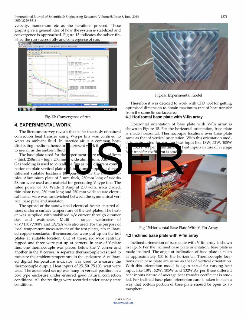
4.2 Inclined base plate with V-fin array Inclined orientation of base plate with V-fin array is shown
in Fig-16. For the inclined base plate orientation, base plate is made inclined. The angle of inclination of base plate is taken as approximately 450 to the horizontal. Thermocouple loca-tions over base plate are same as that of vertical orientation. With this orientation model is again tested for varying heat input like 18W, 52W, 105W and 132W.As per these different heat inputs nature of average heat transfer coefficient is stud-ied. For inclined base plate orientation care is taken in such a way that bottom portion of base plate should be open to at-mosphere.
IJSER

International Journal of Scientific & Engineering Research, Volume 5, Issue 6, June-2014 1372 ISSN 2229-5518
IJSER © 2014 http://www.ijser.org
Fig-16: Inclined Base Plate With V-Fin Array
4.3 Vertical base plate with V-fin array
Fig-17: Vertical Plate With V-Fin Array
Vertical orientation of base plate with V-fin array is shown in Fig-17. For the vertical base plate orientation, base plate is made exactly vertical. It is hanged vertically for good natural convection condition. The angle of inclination of base plate is taken as approximately 900 to the horizontal. Thermocouple locations over base plate are same as that of other orientations. With this orientation model is again tested for varying heat input like 18W, 52W, 105W and 132W.As per these different heat inputs nature of average heat transfer coefficient is stud-ied. For vertical base plate orientation care is taken in such a way that bottom, top, left and right portion of base plate should be open to atmosphere for good natural convection conditions. The product of voltage and current is taken as heat input. To measure the temperature on different locations of base plate four thermocouples are used. Average of all the thermocouple reading is taken which shows the average tem-perature over the base plate. Similarly some thermocouples are used to measure the average ambient temperature. Finally for experimental value of average heat transfer coefficient is obtained by using the equation of Newton’s law of cooling as below,
TABLE -1: EXPERIMENTAL READINGS FOR VERTICAL PLATE WITH V-
FIN ARRAY SR NO.
VOLT-AGE
(VOLTS)
CUR-RENT (AM-
PERE)
HEAT INPUT
IN WATT
TAVG
0C
TAMB
0C
∆T 0C
1 60 0.3 18 43 27 16
2 80 0.65 52 65 27 38
3 105 1.0 105 86 27 59
4 120 1.1 132 97 27 70
5. RESULTS AND DISCUSSION From the results of post processing the temperature varia-
tions on base plate due to various fin angles were found. The angle at which the temperature difference was minimum i.e. convective heat transfer coefficient was maximum, is the angle of interest for actual experimentation. Thus the angle of V-fin can be optimized. The optimized V-fin with base plate was tested for different heat input and different orientations. 5.1 Post processing
Fig-18: Temperature Variations on V-Fin Base Plate
Fig-19: Velocity Contour of V-Fin Model
The results that are obtained after the processing can be
IJSER

International Journal of Scientific & Engineering Research, Volume 5, Issue 6, June-2014 1373 ISSN 2229-5518
IJSER © 2014 http://www.ijser.org
viewed in the CFX post processor. In this, various parameters can be graphically seen. The streamlines, velocity vectors, pressures gradients, temperature contours are some of the major parameters that can be viewed. 5.2 Results of CFD analysis for varying included V-fin angles with constant heat input
The total area is obtained directly from Pro/E. The temper-ature difference is as indicated by the CFX results for various angles and the heat transfer coefficient is calculated. In CFD, different V-fin angles like 00 to 1800 for constant heat input like 105W are analyzed and corresponding to this average heat transfer coefficients 5.05 to 2.85 in W/m2K are obtained. It is clear that the average heat transfer coefficient is maximum, when the included angle of the V-fins is 600. The value of the heat transfer coefficient goes on increasing, reaches a maxi-mum value at 600 and slowly decreases. The graph is plotted for heat transfer coefficient in W/m2K versus various V-fin angles in degree (0) for constant heat input. The nature of the graph is shown in Fig-20.
Fig-20: Heat transfer coefficient (W/m2K) V/s Included V-fin angle in (0)degrees
5.3 Results of CFD analysis for 60° included angle and varying heat input
Since the variation in fin angles gave a maximum heat transfer coefficient at 600, so the same model is tested in CFX for varying heat inputs like 10W, 18W, 37.5W,52W, 72W,105W,132W.The increase in the heat input increases the average heat transfer coefficient. The graph is also plotted for the optimized model for varying heat input. The nature of graph is increasing in the value of average heat transfer coeffi-cient with increase in heat input shown in (Fig-21).
Fig-21: Heat Transfer Coefficient (W/m2K) V/s Heat Input (W)
5.4 Experimental analysis for vertical, horizontal and inclined heated plate orientation
The above discussion early indicates the highest heat trans-fer coefficient for 60o included angle. The experimental mod-els for the same angle with three different orientations are made as Vertical V-fin array model, Horizontal V-fin array model and Inclined V-fin array model. Vertical V-fin array model is analyzed for varying heat inputs as 18W, 52W, 105W and 132W and yields the corresponding heat transfer coeffi-cient as 3.52 W/m2K to 5.92 W/m2K respectively. Similarly, horizontal V-fin array model and inclined V-fin array model are analyzed experimentally for varying same heat inputs as 18W, 52W, 105W and 132W and corresponding heat transfer coefficients were obtained as 2.45 W/m2K to 5.30 W/m2K for horizontal V-fin array model and 2.82 W/m2K to 5.67 W/m2K for inclined V-fin array model. It was found that that as com-pared to horizontal V-fin array model and inclined plate V-fin array model, Vertical plate with V-fin array model with same surface area give greater heat transfer coefficient. It was due to the less thickness development of boundary layer for vertical plate with V-fin. The graph of heat transfer coefficient versus varying heat input for vertical, inclined and horizontal V-fin array models showed the following trend.
Vertical base plate Inclined base plate Horizontal base plate Fig-22:Heat Transfer Coefficient (W/m2K) V/s Varying Heat
Input (W)
IJSER
International Journal of Scientific & Engineering Research, Volume 5, Issue 6, June-2014 1374 ISSN 2229-5518
IJSER © 2014 http://www.ijser.org
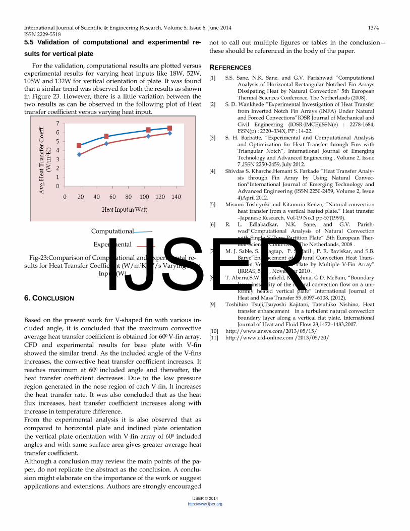
5.5 Validation of computational and experimental re-sults for vertical plate
For the validation, computational results are plotted versus experimental results for varying heat inputs like 18W, 52W, 105W and 132W for vertical orientation of plate. It was found that a similar trend was observed for both the results as shown in Figure 23. However, there is a little variation between the two results as can be observed in the following plot of Heat transfer coefficient versus varying heat input.
Computational
Experimental
Fig-23:Comparison of Computational and Experimental re-sults for Heat Transfer Coefficient (W/m2K) V/s Varying Heat
Input (W)
6. CONCLUSION
Based on the present work for V-shaped fin with various in-cluded angle, it is concluded that the maximum convective average heat transfer coefficient is obtained for 600 V-fin array. CFD and experimental results for base plate with V-fin showed the similar trend. As the included angle of the V-fins increases, the convective heat transfer coefficient increases. It reaches maximum at 600 included angle and thereafter, the heat transfer coefficient decreases. Due to the low pressure region generated in the nose region of each V-fin, It increases the heat transfer rate. It was also concluded that as the heat flux increases, heat transfer coefficient increases along with increase in temperature difference. From the experimental analysis it is also observed that as compared to horizontal plate and inclined plate orientation the vertical plate orientation with V-fin array of 600 included angles and with same surface area gives greater average heat transfer coefficient. Although a conclusion may review the main points of the pa-per, do not replicate the abstract as the conclusion. A conclu-sion might elaborate on the importance of the work or suggest applications and extensions. Authors are strongly encouraged
not to call out multiple figures or tables in the conclusion—these should be referenced in the body of the paper.
REFERENCES [1] S.S. Sane, N.K. Sane, and G.V. Parishwad “Computational
Analysis of Horizontal Rectangular Notched Fin Arrays Dissipating Heat by Natural Convection” 5th European Thermal-Sciences Conference, The Netherlands (2008).
[2] S. D. Wankhede “Experimental Investigation of Heat Transfer from Inverted Notch Fin Arrays (INFA) Under Natural and Forced Convections”IOSR Journal of Mechanical and Civil Engineering (IOSR-JMCE)ISSN(e) : 2278-1684, ISSN(p) : 2320–334X, PP : 14-22.
[3] S. H. Barhatte, “Experimental and Computational Analysis and Optimization for Heat Transfer through Fins with Triangular Notch”, International Journal of Emerging Technology and Advanced Engineering , Volume 2, Issue 7 ,ISSN 2250-2459, July 2012.
[4] Shivdas S. Kharche,Hemant S. Farkade “Heat Transfer Analy-sis through Fin Array by Using Natural Convec-tion”International Journal of Emerging Technology and Advanced Engineering (ISSN 2250-2459, Volume 2, Issue 4)April 2012.
[5] Misumi Toshiyuki and Kitamura Kenzo, “Natural convection heat transfer from a vertical heated plate.” Heat transfer –Japanese Research, Vol-19 No.1 pp-57(1990).
[6] R. L. Edlabadkar, N.K. Sane, and G.V. Parish-wad“Computational Analysis of Natural Convection with Single V-Type Partition Plate” ,5th European Ther-mal-Sciences Conference, The Netherlands, 2008 .
[7] M. J. Sable, S. J. Jagtap, P. S. Patil , P. R. Baviskar, and S.B. Barve“Enhancement of Natural Convection Heat Trans-fer on Vertical Heated Plate by Multiple V-Fin Array” IJRRAS, 5 (2) , November 2010 .
[8] T. Aberra,S.W. Armfield, M. Behnia, G.D. McBain, “Boundary layer instability of the natural convection flow on a uni-formly heated vertical plate” International Journal of Heat and Mass Transfer 55 ,6097–6108, (2012).
[9] Toshihiro Tsuji,Tsuyoshi Kajitani, Tatsuhiko Nishino, Heat transfer enhancement in a turbulent natural convection boundary layer along a vertical flat plate, International Journal of Heat and Fluid Flow 28,1472–1483,2007.
[10] http://www.ansys.com/2013/05/15/ [11] http://www.cfd-online.com /2013/05/20/
IJSER