Embed Size (px)
Citation preview

Kaunas University of Technology
Mechanical engineering faculty
Study of Ion propulsion technology and possible practical
applications
Masters’s Final Degree Project
Aeronautical Engineering (6211EX024)
Project author: MD-M-8/1 Student
Rytis Nykštelis
Project manager:
Kaunas, 2019
2
Kaunas University of Technology
Faculty of Mechanical Engineering and Design
Study of Ion propulsion technology and possible practical
applications
Masters’s Final Degree Project
Aeronautical Engineering (6211EX024)
Rytis Nykštelis
Project author
Assoc. prof. dr Sigitas Kilikevičius
Supervisor
Abbreviation of the position, name and
surname of the reviewer
Reviewer
Kaunas, 2021

Kaunas University of Technology
Faculty of Mechanical Engineering and Design
Rytis Nykštelis
Study of Ion propulsion technology and possible practical
applications
Declaration of Academic Integrity
I confirm the following:
1. I have prepared the final degree project independently and honestly without any violations
of the copyrights or other rights of others, following the provisions of the Law on Copyrights and
Related Rights of the Republic of Lithuania, the Regulations on the Management and Transfer of
Intellectual Property of Kaunas University of Technology (hereinafter – University) and the ethical
requirements stipulated by the Code of Academic Ethics of the University;
2. All the data and research results provided in the final degree project are correct and obtained
legally; none of the parts of this project are plagiarised from any printed or electronic sources; all
the quotations and references provided in the text of the final degree project are indicated in the list
of references;
3. I have not paid anyone any monetary funds for the final degree project or the parts thereof
unless required by the law;
4. I understand that in the case of any discovery of the fact of dishonesty or violation of any
rights of others, the academic penalties will be imposed on me under the procedure applied at the
University; I will be expelled from the University and my final degree project can be submitted to
the Office of the Ombudsperson for Academic Ethics and Procedures in the examination of a
possible violation of academic ethics.
Rytis Nykštelis
Confirmed electronically

Kaunas University of Technology
Faculty of Mechanical Engineering and Design
Study programme: Aeronautical Engineering (6211EX024)
Task of the Master's Final Degree Project
Given to the student: Rytis Nykštelis
1. Title of the Project:
in English „Study of Ion propulsion technology and possible practical applications“
in Lithuanian „Joninės traukos technologijos tyrimas ieškant praktinio pritaikymo“
2. Aim of the Project:
To research Ion propulsion technology and ascertain whether or not this technology can be applied with current materials to replace or enhance the systems of today.
3. Tasks of the Project:
To Study currently available ion propulsion technologies and review papers on the subject while selecting the most efficient possible methods to apply ion propulsion.
To design an ion propelled aircraft, compare it to conventional propulsion systems.
To design and compare an EHD powered ventilation system to that of a conventional fan.
To perform physical experiments and research with Ion propulsion
4. Structure of the Text Part:
Literature analysis, drone design, cooling system design, physical experimentation
5. Consultants of the Project:
Author of the Final Degree Project 2021-02-01
(name, surname, date)
Supervisor of the Final Degree Project 2021-02-01
(abbreviation of the position, name, surname, date)
Head of Study Programmes prof. Artūras Keršys 2021-02-01
(abbreviation of the position, name, surname, date)
Rytis Nykštelis “Study of Ion propulsion technology and possible practical applications”. Master's
Final Degree Project / supervisor Assoc. prof. dr Sigitas Kilikevičius Supervisor; Faculty of
Mechanical Engineering and Design, Kaunas University of Technology.
Study field and area (study field group): Aeronautical Engineering (E14), Engineering Science.
Keywords: Electo hydrodynamics, electro aerodynamics, lighter than air aircraft.
Kaunas, 2021. 49
Summary
This work is about ion propulsion phenomenon, commonly refered to as electro hydrodynamics
(EHD), or electro aerodynamics (EAD), the purpose of the work is to review research papers about
the phenonmenon and search for a possbile practical application for it. The work features designs of
a lighter than air vehicle using the ion thrust as a propulssion device, as well as a design of a
cooling system, that emulates a computer coolers performace. Comparisons between the designed
systems and the standard systems are made. Practical experiments with ion propulsion are atempted.

Rytis Nykštelis “Jonnės traukos technologijos tyrimas ieškant praktinio pritaikymo”. Magistro
baigiamasis projektas / Doc. Dr. Sigitas Kilikevičius; Kauno technologijos universitetas,
Mechanikos inžinerijos ir dizaino fakultetas.
Studijų kryptis ir sritis (studijų krypčių grupė): Aeronautikos inžinerija (E14), Inžinerijos mokslai.
Reikšminiai žodžiai:Electro hidrodinamika, electro aerodinamika, legvenė už orą skraidyklė.
Kaunas, 2021. 49 p.
Santrauka
Šiame darbe kalbama apie joninės traukos fenomeną, dažnai vadinamą elektro hidrodinamikos arba
elektro aerodinamikos reiškiniu, darbe atliekama mokslinių straipsnių analizė apie šį reiškinį,
taipogi parenkami tendencyviausi darbai ieškant praktinio fenonemo pritaikymo. Darbe aprašomas
lengvesnio už orą orlaivio varomo joninės traukos stūma dizainas ir aušinimo sistemos pritaikytos
aušinti komputiurį. Atliekami palyginimai tarp paprastų sistemų ir elektro hidrodinaminių. Bandomi
atlikti praktiniai eksperimentai.
7
Table of contents
List of figuires ..................................................................................................................................... 8
List of abbreviations and terms ........................................................................................................... 9
Introduction ....................................................................................................................................... 10
Literature survey ................................................................................................................................ 11
Relevance of study: ........................................................................................................................ 11
Novelty of scientific/engineering research .................................................................................... 13
History of Ion propulsion: .............................................................................................................. 15
Physical phenomenon of ion propulsion. ....................................................................................... 17
Creation of electro hydrodynamics model using finite element methods...................................... 22
Possible applications for ion propulsion. ....................................................................................... 25
Further study goals ......................................................................................................................... 26
Powering a drone using EAD ............................................................................................................ 27
Structure design and analysis: ........................................................................................................ 31
EAD-LAT Blimp design specifications: ........................................................................................ 34
Conclusion regarding the feasibility of EAD-LAT drone ............................................................. 35
Using electric air flow for cooling ..................................................................................................... 36
Designing a EHD cooling system .................................................................................................. 39
Conclusion regarding the feasibility of an EHD powered cooling system .................................... 43
Experimentation performed with regards to EHD technology .......................................................... 44
Initial preparation stage ................................................................................................................. 44
Experimentation stage .................................................................................................................... 45
Conclusions ....................................................................................................................................... 46
List of references ............................................................................................................................... 47

8
List of figuires
Figure 1 MIT Ion powered drone plane [9] ....................................................................................... 13
Figure 2 Takeoff of a micro fabricated ionocraft at 1000 Fps, Daniel S. Drew [11] ........................ 14
Figure 3 Ion drive airship concept[12] .............................................................................................. 15
Figure 4 Typical Ionocraft construction [20] .................................................................................... 17
Figure 5 Explanation of ionocraft function [22] ................................................................................ 18
Figure 6 Explanation of particle movement in ionocraft [22] ........................................................... 18
Figure 7 a) single stage thruster electrodes vs b) Dual stage thruster electrodes [23] ...................... 20
Figure 8 EHD lifter model [24] ......................................................................................................... 23
Figure 9 Experimental data and simulation comparison ................................................................... 24
Figure 10 Solidworks Flow simulation of the blimp surface ............................................................ 29
Figure 11 isometric view of the drone with the EAD propulsion system attached. .......................... 30
Figure 12 EAD-LAT drone side view ............................................................................................... 30
Figure 13 a basic structure concept for the drone .............................................................................. 31
Figure 14 skin holding structure attached to battery pack and thruster structure .............................. 31
Figure 15 Static analysis of the structure with gravity load .............................................................. 32
Figure 16 Static study with battery mass load ................................................................................... 32
Figure 17 Static study with Aluminum 2014 T6 ............................................................................... 33
Figure 18 Electrical architecture of the MIT high voltage power converter [28] ............................. 34
Figure 19 EHD cooling device design from the “Numerical development of EHD cooling systems
for laptop applications” team [36] ..................................................................................................... 38
Figure 20 CFD calculations of a section for EHD cooling system ................................................... 40
Figure 21 Ion thruster rows for the cooling device ........................................................................... 41
Figure 22 cone box design of the cooling device .............................................................................. 41
Figure 23 Pressure distribution inside of the cooling device ............................................................ 42
Figure 24 airflow velocity plots ........................................................................................................ 42
Figure 25 simple “Panasonic” second hand kinescope monitor to be used as a high voltage power
supply. ............................................................................................................................................... 44
Figure 26 Flyback transformer .......................................................................................................... 45

9
List of abbreviations and terms
Abbreviations:
Assoc. prof. – associate professor;
Lect. – lecturer;
Prof. – professor.
EHD – Electro hydro dynamics
EAD – Electro aero dynamics
LAT – Lighter than air vehicle
10
Introduction
Ionocraft are ion-propelled aircraft that use electro hydrodynamics or EHD to create thrust
necessary to fly, although at the current time their flight is limited to barely hold the thrust
producing section in the air. Though throughout the years many designs have been created and
tested, few to none have actually garnered any success or critical acclaim. This, in part, is caused by
the innate weakness of the ion thrust generations when compared to alternative thrust sources, even
still, the upsides of the ion thruster must not be ignored when thinking about possible applications.
This study will analyze Ionocrafts, the physics behind what makes them function, and attempt to
postulate a practical application for this technology. A few steps that include looking into the
history of similar technologies that use electro hydrodynamic to function and review at what can be
learnt from the mistakes or achievements of the past, overview the physical forces and how energy
is transferred to make the device fly, what parameters determine the efficiency and power of this
device as well as an attempt to suggest an application in which this technology could be used will
be required. The aim of this project is to conduct a study of literature regarding atmospheric ion
propulsion, various types of different designs and applications, as well as look into different ways
of studying the phenomenon. Tasks required to achieve this aim are:
- A literature survey about the history of ion craft.
- A literature survey about the physics behind ion propulsion.
- A survey about computational model generation for simulations of ion propulsion.
- Presentation and modeling of an Ion propelled drone.
- Calculation of a ion powered ventilation system and comparison to conventional
ventilation systems.
- Practical experiments with ion propulsion
11
Literature survey
In this section review of various papers and data is made, the section is divided in parts:
- Relevance of study
- Novelty of scientific/engineering research
- History of ion propulsion.
- Physical phenomenon of ion propulsion.
- Creation of electro hydrodynamics model using finite element methods.
- Possible applications for ion propulsion.
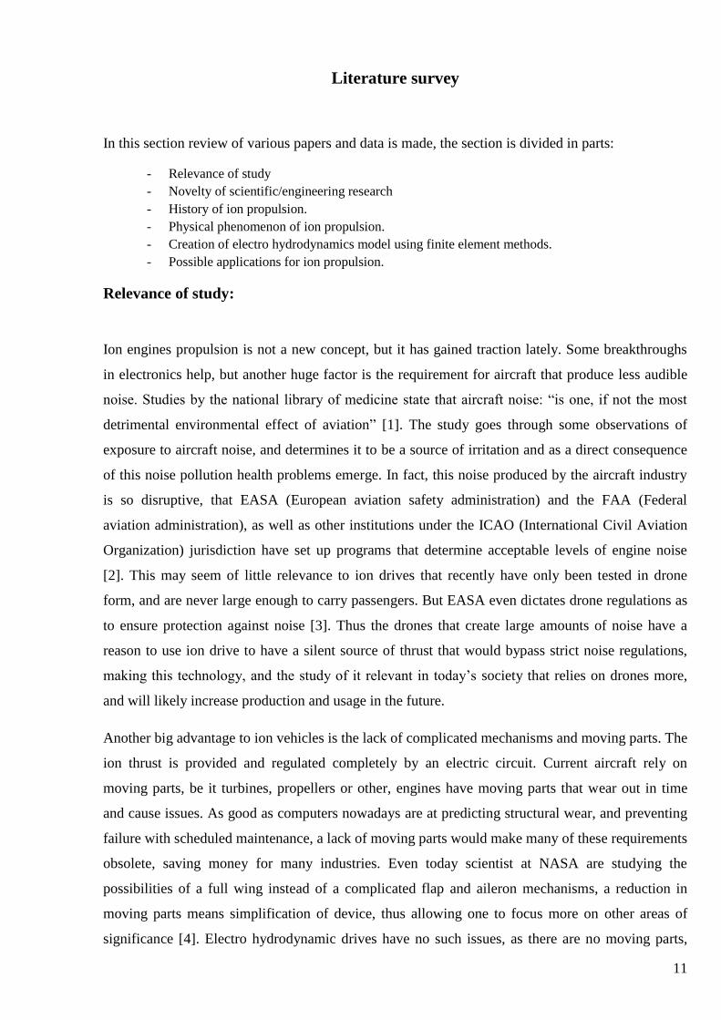
Relevance of study:
Ion engines propulsion is not a new concept, but it has gained traction lately. Some breakthroughs
in electronics help, but another huge factor is the requirement for aircraft that produce less audible
noise. Studies by the national library of medicine state that aircraft noise: “is one, if not the most
detrimental environmental effect of aviation” [1]. The study goes through some observations of
exposure to aircraft noise, and determines it to be a source of irritation and as a direct consequence
of this noise pollution health problems emerge. In fact, this noise produced by the aircraft industry
is so disruptive, that EASA (European aviation safety administration) and the FAA (Federal
aviation administration), as well as other institutions under the ICAO (International Civil Aviation
Organization) jurisdiction have set up programs that determine acceptable levels of engine noise
[2]. This may seem of little relevance to ion drives that recently have only been tested in drone
form, and are never large enough to carry passengers. But EASA even dictates drone regulations as
to ensure protection against noise [3]. Thus the drones that create large amounts of noise have a
reason to use ion drive to have a silent source of thrust that would bypass strict noise regulations,
making this technology, and the study of it relevant in today’s society that relies on drones more,
and will likely increase production and usage in the future.
Another big advantage to ion vehicles is the lack of complicated mechanisms and moving parts. The
ion thrust is provided and regulated completely by an electric circuit. Current aircraft rely on
moving parts, be it turbines, propellers or other, engines have moving parts that wear out in time
and cause issues. As good as computers nowadays are at predicting structural wear, and preventing
failure with scheduled maintenance, a lack of moving parts would make many of these requirements
obsolete, saving money for many industries. Even today scientist at NASA are studying the
possibilities of a full wing instead of a complicated flap and aileron mechanisms, a reduction in
moving parts means simplification of device, thus allowing one to focus more on other areas of
significance [4]. Electro hydrodynamic drives have no such issues, as there are no moving parts,
12
thus the only wear out is the electric components such as batteries and conductors, which you can
easily monitor with voltage and conductivity drops, not requiring large scale disassembly to gain
access to systems. The simplicity of the device would make modularity easy to implement and
maintain. Current technologies keep promising modular designs, but complicated systems making
adding or subtracting components difficult. A simple system such as a Ionocraft would make
upgrading or downgrading a device simpler than conventional aircraft, where one has to assume the
reaction and effect on all systems. With a tendency for aircraft to use more and more complicated
mechanisms, and scientist and engineers working on simpler more efficient and less complex
mechanisms, this could very well be a breakthrough which would allow ion thrust vehicles to
become a viable type of thrust provider for aircraft. Also, like all other electric engines, their
emissions are only those that are produced by the electricity production process, meaning none [5].
As Gad Hayisraeli writes, “A lifter is an electrical propulsion device which is based on an
asymmetrical capacitor without any moving parts.”[6] Indeed, the lack of moving parts seems to be
the most promising part of this design. While other propulsion systems have complex ways of
achieving thrust, like spinning turbines. The lifter can be surprisingly reliable due to lack of a
moving mechanism that would wear down due to friction [7].
Taking into account all the above mentioned things, the study is assumed to be relevant, and in fact,
it will be becoming more and more relevant the more restrictions are implemented on conventional
flight by aviation authorities.
13
Novelty of scientific/engineering research
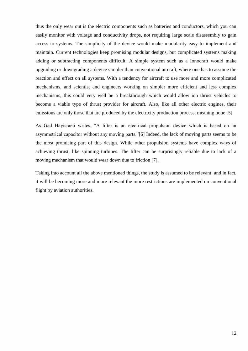
Just recently, on 21st of November 2018, a huge breakthrough was made by a team in MIT
(Massachusetts Institute of Technology), where a team of engineers successfully performed a test
flight of a drone with no moving parts, powered by ion thrusts (fig. 1). While not exactly a lifter this
craft proves that ionocraft have potential to be more than a fun science project. The teams final
design was a large lightweight gilder, however the aircraft that has a giant long wing, underneath,
two rows and 4 columns of wing long lifter thrusters, that consist of a wire set to a positive voltage
of +20000V, while behind it at a set distance there is an airfoil made of foam surrounded by
aluminum foil set to a -20000V [8]. The energized particles moving between them create a sort of
wind effect that push the entire aircraft forward, and while it is unable to lift off unassisted, the
possibility of extended periods of prolonged steady flight are available. The entire aircraft is super
light weighing only at around 2.3 kg, while having an amazing 5 meter wingspan. In the fuselage of
the plane are hidden stacks of lithium-polymer batteries. These are specially modified to provide the
power to the six stage full-wave Cockcroft-Walkton voltage multiplier that they build in house to
provide the 40000V required to charge the wires and airfoils to create the electrical field required to
accelerate the air particle around them. [9]
Another project that has been on the verge of breakthrough to mass EHD use is flying microrobot.
Daniel S. Drew and Kristofer S. J. Pister at the University of Berkeley, California, have been
working on micro scale flying craft for a few years now. Their vision is to use Electrohydrodynamic
force to propel small drones, that could be used for a variety of applications, most important of
which is search and rescue applications where swarms of drones could be used to look for
survivors. Similar projects have been presented by Harvard University with their microrobots the
Robobees [10], however, these types of devices use electromagnetic or piezoelectric mechanisms to
flap the wings of the robot. This not only adds moving parts, but also increases the complexity of
Figure 1 MIT Ion powered drone plane [9]
14
the device. These devices have a high level of degrees of freedom that is difficult to control when
performing precise directional flight. With EHD devices there are no moving parts, they device is
significantly easier to build, as well as the devices can use a quadcopter flight scheme that is
extensively researched and has a variety of controller schemes available, instead of the highly
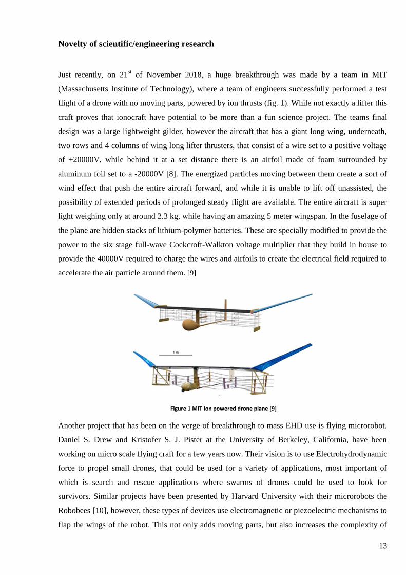
unstable and hard to control winged device. In 2017, they performed a horizontal flight test with a
ionocraft that weighed 10 mg, was 1.8 cm by 1.8 cm and operated at 2400 volts (fig. 2). What their
team discovered is that ionocraft, while having very bad thrust density, too low to be used to carry
passengers, when scaled down it scales invariantly, meaning that the thrust remains the same, even
for a very small device, thus making super small EHD aircraft a possibility. The team performed a
couple of studies of ionocraft characteristics that will be discussed later in this study.[11]
Figure 2 Takeoff of a micro fabricated ionocraft at 1000 Fps, Daniel S. Drew [11]
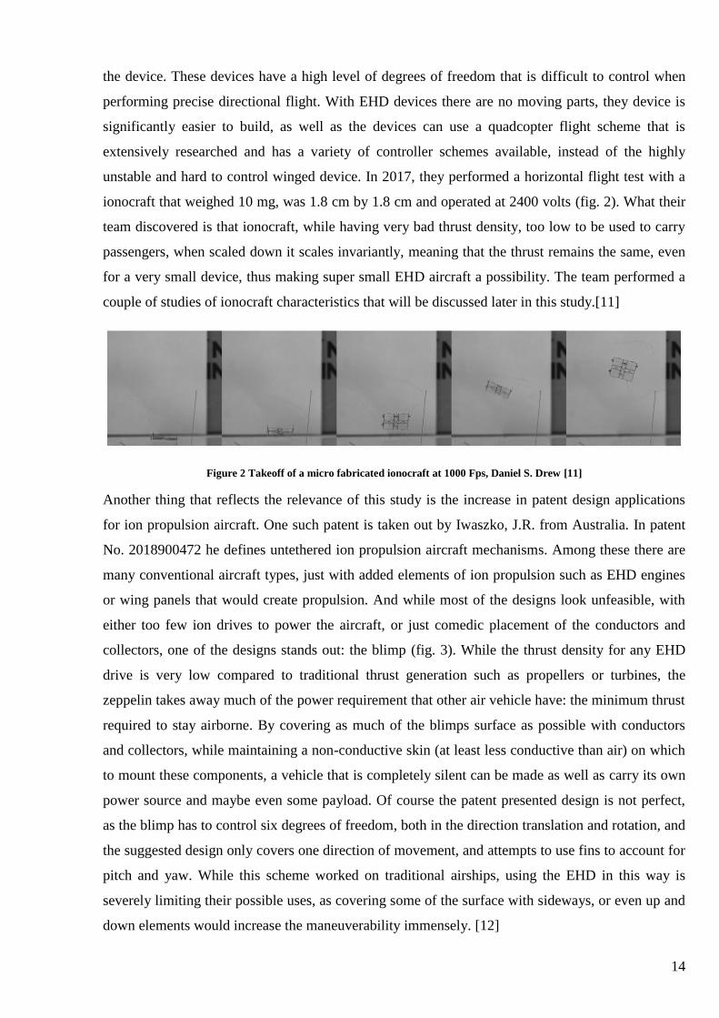
Another thing that reflects the relevance of this study is the increase in patent design applications
for ion propulsion aircraft. One such patent is taken out by Iwaszko, J.R. from Australia. In patent
No. 2018900472 he defines untethered ion propulsion aircraft mechanisms. Among these there are
many conventional aircraft types, just with added elements of ion propulsion such as EHD engines
or wing panels that would create propulsion. And while most of the designs look unfeasible, with
either too few ion drives to power the aircraft, or just comedic placement of the conductors and
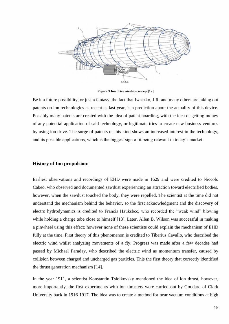
collectors, one of the designs stands out: the blimp (fig. 3). While the thrust density for any EHD
drive is very low compared to traditional thrust generation such as propellers or turbines, the
zeppelin takes away much of the power requirement that other air vehicle have: the minimum thrust
required to stay airborne. By covering as much of the blimps surface as possible with conductors
and collectors, while maintaining a non-conductive skin (at least less conductive than air) on which
to mount these components, a vehicle that is completely silent can be made as well as carry its own
power source and maybe even some payload. Of course the patent presented design is not perfect,
as the blimp has to control six degrees of freedom, both in the direction translation and rotation, and
the suggested design only covers one direction of movement, and attempts to use fins to account for
pitch and yaw. While this scheme worked on traditional airships, using the EHD in this way is
severely limiting their possible uses, as covering some of the surface with sideways, or even up and
down elements would increase the maneuverability immensely. [12]
15
Figure 3 Ion drive airship concept[12]
Be it a future possibility, or just a fantasy, the fact that Iwaszko, J.R. and many others are taking out
patents on ion technologies as recent as last year, is a prediction about the actuality of this device.
Possibly many patents are created with the idea of patent hoarding, with the idea of getting money
of any potential application of said technology, or legitimate tries to create new business ventures
by using ion drive. The surge of patents of this kind shows an increased interest in the technology,
and its possible applications, which is the biggest sign of it being relevant in today’s market.
History of Ion propulsion:
Earliest observations and recordings of EHD were made in 1629 and were credited to Niccolo
Cabeo, who observed and documented sawdust experiencing an attraction toward electrified bodies,
however, when the sawdust touched the body, they were repelled. The scientist at the time did not
understand the mechanism behind the behavior, so the first acknowledgment and the discovery of
electro hydrodynamics is credited to Francis Hauksbee, who recorded the “weak wind” blowing
while holding a charge tube close to himself [13]. Later, Allen B. Wilson was successful in making
a pinwheel using this effect; however none of these scientists could explain the mechanism of EHD
fully at the time. First theory of this phenomenon is credited to Tiberius Cavallo, who described the
electric wind whilst analyzing movements of a fly. Progress was made after a few decades had
passed by Michael Faraday, who described the electric wind as momentum transfer, caused by
collision between charged and uncharged gas particles. This the first theory that correctly identified
the thrust generation mechanism [14].
In the year 1911, a scientist Konstantin Tsiolkovsky mentioned the idea of ion thrust, however,
more importantly, the first experiments with ion thrusters were carried out by Goddard of Clark
University back in 1916-1917. The idea was to create a method for near vacuum conditions at high

16
altitudes [15]. The first functional ion thrusters were built by Harold R. Kaufman in 1959 at the
legendary NASA’s Glenn research center. The thrusters featured a gridded electrostatic ion thruster
and used a heavy propellant in Mercury gas. The first suborbital tests began in 1960, and by 1970 a
successful orbital test was concluded [16].
While the ideas of ion thrust was studied in the early twentieth century and the ion wind was
observed even before then, the lifter as a design began when Thomas Townsend Brown connected
an asymmetrical high voltage capacitor to a 100 kilovolt DC input, and discovered that the capacitor
plate created thrust towards one plate of the capacitor. Thomas and another scientist by the name of
Dr. Paul Biefeld issued multiple patents on the new “Lifter” phenomenon they discovered. They,
however believed that they discovered antigravity, as did most people who researched this effect,
and created many theories on the “Electrogravitics” [17]. Nowadays it is known that it is the
movement of particles from a positive charge to a negative that creates an Ion wind that pushes
surround air molecules creating thrust. Later this effect was renamed in their honor to the “Biefeld-
Brown effect” [18]. Following their studies, Brown built a flying disc, which was presented to the
US navy in 1950, although impressive, the technology was still in its infancy, and the disc required
to be tethered to the ground, as it could not lift its own power source. In 1964, the magazine
“Popular Mechanics” published an article about Major de Seversky’s who proposed Ion-propelled
aircraft. The Major presented the media with a working small scale prototype of a lifter, and
managed to incite awe in quite a few people. They called it a magic carpet of the future. And while
the scientists at the time pondered the possibility of using these devices in above normal operating
altitudes of helicopters or other conventional flying machines, it never came to fruition, mostly due
to the abysmal thrust density in the ion drive, as well as the improper battery and conductor
technologies back in the day [19]. However, not all hope was lost. In July 2001, a new design was
proposed when the engineer Jeef Cameron, conducted and experiment on a new version of the lifter
that featured a triangle shape with balsa wood and aluminum foil. Following these successful
experiments another researcher by the name of Jean-Louis Naudin improved the same design
getting the power to weight ration almost all the way up to 1 gram per watt.
The first widely known operational mission to use an ion engine was NASA’s DAWN, It was also
the first mission to orbit two interplanetary bodies, the first mission to orbit around a body in the
asteroid belt, as well as the first mission to orbit a dwarf plane. The thrusters used xenon gas, while
earlier versions of the ion propulsion systems used mercury. Xenon was selected for its low
reactivity and high molecular mass. The ion thrusters used were derived from the NSTAR
technology [20].
17
Physical phenomenon of ion propulsion.
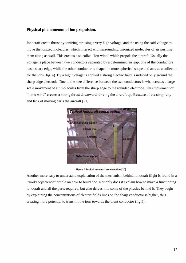
Ionocraft create thrust by ionizing air using a very high voltage, and the using the said voltage to
move the ionized molecules, which interact with surrounding unionized molecules of air pushing
them along as well. This creates a so called “Ion wind” which propels the aircraft. Usually the
voltage is place between two conductors separated by a determined air gap, one of the conductors
has a sharp edge, while the other conductor is shaped in more spherical shape and acts as a collector
for the ions (fig. 4). By a high voltage is applied a strong electric field is induced only around the
sharp edge electrode. Due to the size difference between the two conductors is what creates a large
scale movement of air molecules from the sharp edge to the rounded electrode. This movement or
“Ionic wind” creates a strong thrust downward, driving the aircraft up. Because of the simplicity
and lack of moving parts the aircraft [21].
Another more easy to understand explanation of the mechanism behind ionocraft flight is found in a
“workshopscience” article on how to build one. Not only does it explain how to make a functioning
ionocraft and all the parts required, but also delves into some of the physics behind it. They begin
by explaining the concentrations of electric fields lines on the sharp conductor is higher, thus
creating more potential to transmit the ions towards the blunt conductor (fig 5).
Figure 4 Typical Ionocraft construction [20]
18
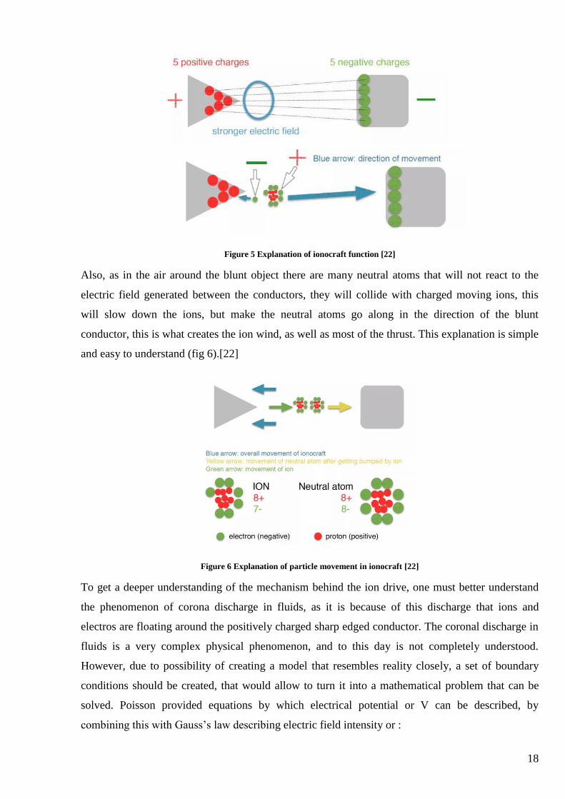
Figure 5 Explanation of ionocraft function [22]
Also, as in the air around the blunt object there are many neutral atoms that will not react to the
electric field generated between the conductors, they will collide with charged moving ions, this
will slow down the ions, but make the neutral atoms go along in the direction of the blunt
conductor, this is what creates the ion wind, as well as most of the thrust. This explanation is simple
and easy to understand (fig 6).[22]
Figure 6 Explanation of particle movement in ionocraft [22]
To get a deeper understanding of the mechanism behind the ion drive, one must better understand
the phenomenon of corona discharge in fluids, as it is because of this discharge that ions and
electros are floating around the positively charged sharp edged conductor. The coronal discharge in
fluids is a very complex physical phenomenon, and to this day is not completely understood.
However, due to possibility of creating a model that resembles reality closely, a set of boundary
conditions should be created, that would allow to turn it into a mathematical problem that can be
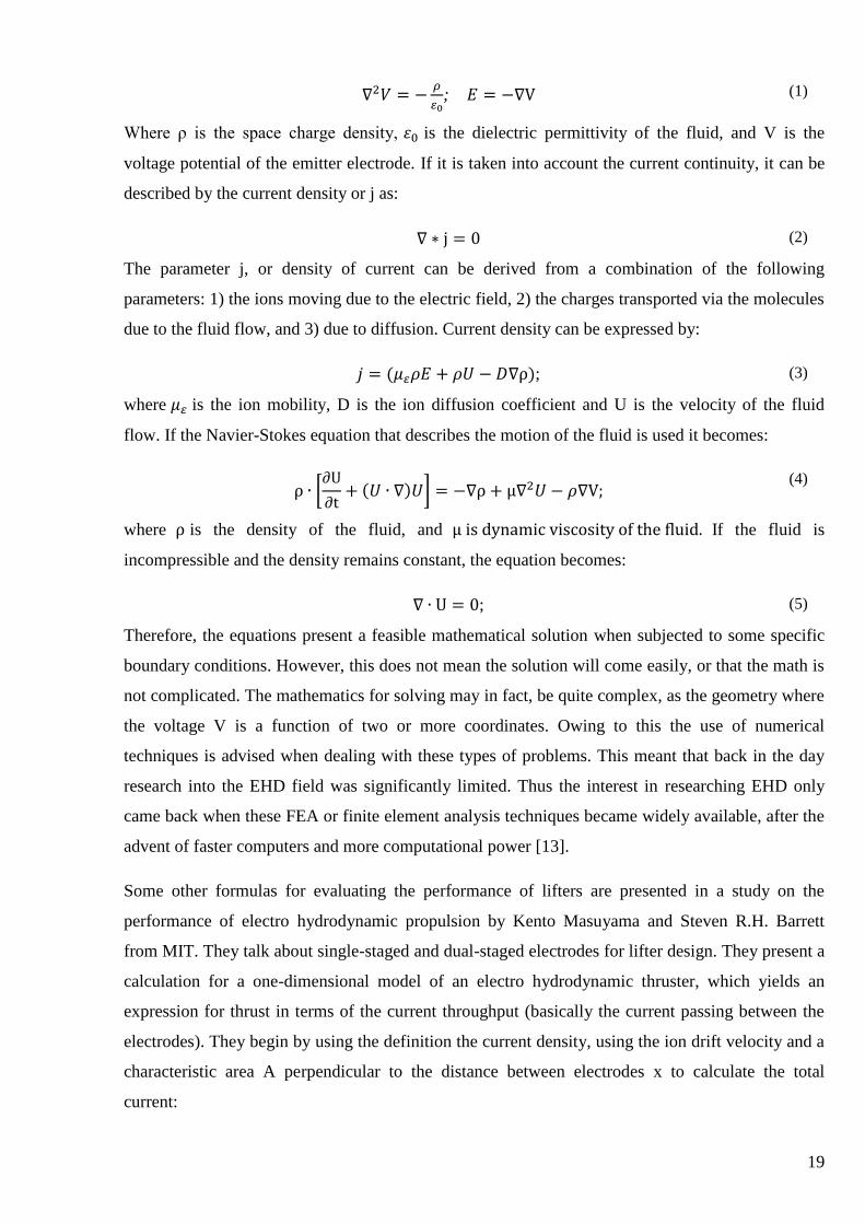
solved. Poisson provided equations by which electrical potential or V can be described, by
combining this with Gauss’s law describing electric field intensity or :
19
∇2𝑉 = −𝜌
𝜀0; 𝐸 = −∇V (1)
Where ρ is the space charge density, 𝜀0 is the dielectric permittivity of the fluid, and V is the
voltage potential of the emitter electrode. If it is taken into account the current continuity, it can be
described by the current density or j as:
∇ ∗ j = 0 (2)
The parameter j, or density of current can be derived from a combination of the following
parameters: 1) the ions moving due to the electric field, 2) the charges transported via the molecules
due to the fluid flow, and 3) due to diffusion. Current density can be expressed by:
𝑗 = (𝜇𝜀𝜌𝐸 + 𝜌𝑈 − 𝐷∇ρ); (3)
where 𝜇𝜀 is the ion mobility, D is the ion diffusion coefficient and U is the velocity of the fluid
flow. If the Navier-Stokes equation that describes the motion of the fluid is used it becomes:
ρ ∙ [∂U
∂t+ (𝑈 ∙ ∇)𝑈] = −∇ρ + μ∇2𝑈 − 𝜌∇V;
(4)
where ρ is the density of the fluid, and μ is dynamic viscosity of the fluid. If the fluid is
incompressible and the density remains constant, the equation becomes:
∇ ∙ U = 0; (5)
Therefore, the equations present a feasible mathematical solution when subjected to some specific
boundary conditions. However, this does not mean the solution will come easily, or that the math is
not complicated. The mathematics for solving may in fact, be quite complex, as the geometry where
the voltage V is a function of two or more coordinates. Owing to this the use of numerical
techniques is advised when dealing with these types of problems. This meant that back in the day
research into the EHD field was significantly limited. Thus the interest in researching EHD only
came back when these FEA or finite element analysis techniques became widely available, after the
advent of faster computers and more computational power [13].
Some other formulas for evaluating the performance of lifters are presented in a study on the
performance of electro hydrodynamic propulsion by Kento Masuyama and Steven R.H. Barrett
from MIT. They talk about single-staged and dual-staged electrodes for lifter design. They present a
calculation for a one-dimensional model of an electro hydrodynamic thruster, which yields an
expression for thrust in terms of the current throughput (basically the current passing between the
electrodes). They begin by using the definition the current density, using the ion drift velocity and a
characteristic area A perpendicular to the distance between electrodes x to calculate the total
current:
20
𝐼 = ∫ 𝑖 ∙ 𝑑𝐴 = ∫ ρ μE ∙ dA = ρμEA; (6)
Where ρ is charge density, μ is the ion mobility, and E is the electric field magnitude. By applying
the Coulomb force on the volume of ions occupying the gap at any instant in time for a single stage
ion thruster:
𝐹𝑆𝑆 = ∫ ρE dV = ∫ ρEA dx =𝐼𝑑
μ
𝑑
0; (7)
Where d are the electrode radii. Using the voltage – current relationship that applies for corona
discharges
𝐼 = 𝐶𝑉(𝑉 − 𝑉0); (8)
With C ∝ μ/d2, the thrust can be expressed as a function of the voltage:
𝐹𝑆𝑆 =𝐶`𝑉(𝑉 − 𝑉0)
𝑑;
(9)
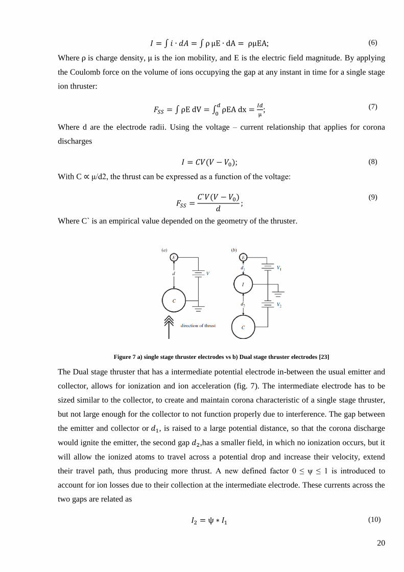
Where C` is an empirical value depended on the geometry of the thruster.
Figure 7 a) single stage thruster electrodes vs b) Dual stage thruster electrodes [23]
The Dual stage thruster that has a intermediate potential electrode in-between the usual emitter and
collector, allows for ionization and ion acceleration (fig. 7). The intermediate electrode has to be
sized similar to the collector, to create and maintain corona characteristic of a single stage thruster,
but not large enough for the collector to not function properly due to interference. The gap between
the emitter and collector or 𝑑1, is raised to a large potential distance, so that the corona discharge
would ignite the emitter, the second gap 𝑑2,has a smaller field, in which no ionization occurs, but it
will allow the ionized atoms to travel across a potential drop and increase their velocity, extend
their travel path, thus producing more thrust. A new defined factor 0 ≤ ψ ≤ 1 is introduced to
account for ion losses due to their collection at the intermediate electrode. These currents across the
two gaps are related as
𝐼2 = ψ ∗ 𝐼1 (10)
21
By taking all this into account the authors produce a formula of:
𝐹𝐷𝑆 = ∫ ρ1𝐸1𝐴 𝑑𝑥 + ∫ ρ2𝐸2𝐴 𝑑𝑥 =𝐼1(𝑑1+ψ𝑑2)
μ𝑑2𝑑1;
(11)
Next, as the most important characteristic for an EHD thruster the authors present the thrust to
power ratio, or F/P, which is a metric that is used to compare EHD thrust to other competing
technologies, they present it as a component of overall efficiency,
𝜂 = 𝐹𝜐/𝑃
(12)
and is proportional to the inverse of thrust SFC. The conventional unit to present SFC is unit of fiel
per hour per measurement of thrust, or kg𝑓−1ℎ−1 , assuming a fuel flow rate of m (kg𝑠−1) with the
fuel having a lower calorific value of 43MJ𝑘𝑔−1, then the thrust calculation becomes:
𝑆𝐹𝐶 =(𝑃𝑡ℎ/𝐿𝐶𝑉 × 602)
𝐹/𝑔;
(13)
where g=9.81𝑚𝑠−2 , 𝑃𝑡ℎ is the heating rate assuming complete usage of fuel, Thus F/P can be
expressed as:
𝐹
𝑃𝑡ℎ(𝑁𝑘𝑊−1)=
0.821
𝑆𝐹𝐶;
(14)
This is what most of the comparison will be drawn from, as the data for SFC of other means of
transport provided.
The input for a single stage electro hydrodynamic thruster is the product of current and
voltage outputs for a given power supply. For a dual-stage thruster, it is the sum of the products for
both power supplies, where currents are related by the parameter psi ψ as mentioned above.
Therefore:
𝐹/𝑃𝑠𝑠 =𝐼𝑑
μIV=
𝑑
μV;
(15)
For a single staged thruster, while dual staged F/P is calculated as:
𝐹
𝑃𝐷𝑆=
𝐼(𝑑1 + ψ𝑑2)
μ𝐼1(𝑉1 + ψ|𝑉2|)=
𝑑1 + ψ𝑑2
μ(𝑉1 + ψ|𝑉2|);
(16)
22
While looking at the formula would imply that efficiency will increase as the air gap d is increased,
the electric field needs sufficient strength to ignite the corona – or no thrust will be produced, and to
be low enough not to cause discharge, otherwise the craft will set on fire. It may also seem that for
the dual staged thruster, efficiency can be varied due to the fixed air gap or 𝑑1, example being
higher thrust by setting a higher volrage and resulting in lower efficiency at take off vs lower
voltage and thrust but higher efficiency. To see the effect of the parameter psi (ψ) on the equation,
the authors expand the efficiency formula to the first order:
𝑑1 + ψ𝑑2
μ(𝑉1 + ψ|𝑉2|)=
𝑑1 + 𝑑2
μ(𝑉1 + |𝑉2|)+
(ψ − 1)(𝑑2𝑉1 − 𝑑1|𝑉2|)
μ(𝑉1 + ψ|𝑉2|)2+ 𝑂(ψ2)
(17)
The first term is independent of ψ and positive, while the denominator of the second term is
positive, but with the defined factor 0 ≤ ψ ≤ 1, and with 𝑉1/𝑑1 > 𝑉2/𝑑2 in order to unsure
ionization to only the top gap of the dual stage thruster, the numerator is negative. As such, a larger
value of ψ correspond to a lrager portion of the current crossing the second gap is expected to
minimize loss and generate more thrust.
To calculate the quality of a thruster configuration, the author presents a non-dimensional efficiency
to be able to compare their experimental thrust to power ration with the nominal theoretical
condition. In the case for a dual stage thruster, the ideal condition is that no ions are lost due to the
intermediate electrode, thus for both types of thrusters:
𝛺 =𝐹μ𝑉𝑡𝑜𝑡𝑎𝑙
𝑃𝑑𝑡𝑜𝑡𝑎𝑙
(18)
Where both F and P can be experimentally measured [23].
Where these formulas explain how to compare results with experimental data, for accurate
calculations the use of finite element methods is advised. The model is analyzed further on.
Creation of electro hydrodynamics model using finite element methods.
As it was described earlier, the mathematics behind calculations on any flow are complex and warrant using
computational methods. Due to the added complexity of electro hydrodynamics that require to analyze
current flow as well as corona effect, this is even truer. Thus in this section some works that use finite
element or other computational methods to perform analysis on models representing EHD thrusters or drives
will be analyzed.

23
First off, to do any form of calculations involving a finite element analysis a model has to be created,
beginning with geometry, luckily, the geometry for a simple lifter is not hard to recreate in a computer
environment, as a simple cross section two dimensional analysis will suffice, under the assumption that
parameters remain the same all along the conductor axis. The ionocraft lifting unit is an asymmetrical
capacitor with a small scale positive conductor (emitter), and a comparatively larger collector (fig. 8) [24].
To be able to calculate a few assumptions have to be made:
1) In a certain region, where the electric density becomes larger than a certain threshold, the air
will become completely ionized, meaning molecules will be charged by a unit, outside of
this region the air is not completely ionize. The threshold is represented by ThV (threshold
volume, V/m) The proportion is represented by the charge density, or coefficient beta (β)
(C/𝑚3).
2) Charges uniform and statistically distribute in the ionization region, this means that the
volume force is a simple multiplication of coefficient β and electric field density E
With these assumptions, a description of how the electric field will be interacting with the air
molecules can be made. This is described by the two parameters of ThV and β.
Though this method presents far fewer parameters than other computational methods, it is important
to take into account that β is still just an averaged charge density that is assumed to be a constant as
space varies. Compared with the total charge density possible of 3.9 * 106𝐶 ∙ 𝑚−3, if one molecude
provides one unit and under 1 atmosphere pressure and around 300 Kelvin temperature, the choice
of β parameters at 0.115 C∙ 𝑚−3 is still quite small in proportion.
For given ionization in particular region, charges will be accelerated by the electric field, and
momentum will be delivered by collisions to unionized molecules outside the ionization field. To
Figure 8 EHD lifter model [24]
24
represent this proportion the parameter β was introduced. Counterforce can be calculated by using
the formula:
𝐹 = − ∫ ∇𝑝𝑑3𝑥 (19)
Here it is possible to see that the force is not produced by a pressure difference, rather it is treated as
a recoil of the flow instead of a pressure effect.
By using a turbulent flow k-ϵ model framework, and a reference pressure set to 1∙ 102[atm] to avoid
divergence. In addition for the convenience of the solver, an inlet and outlet should be set, so that
boundary conditions are met.
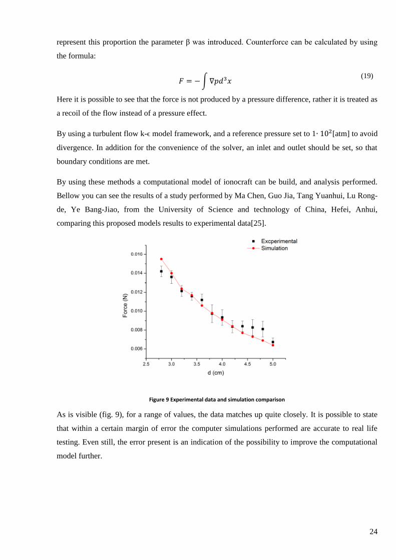
By using these methods a computational model of ionocraft can be build, and analysis performed.
Bellow you can see the results of a study performed by Ma Chen, Guo Jia, Tang Yuanhui, Lu Rong-
de, Ye Bang-Jiao, from the University of Science and technology of China, Hefei, Anhui,
comparing this proposed models results to experimental data[25].
Figure 9 Experimental data and simulation comparison
As is visible (fig. 9), for a range of values, the data matches up quite closely. It is possible to state
that within a certain margin of error the computer simulations performed are accurate to real life
testing. Even still, the error present is an indication of the possibility to improve the computational
model further.
25
Possible applications for ion propulsion.
While electro hydrodynamics and ion propulsion has been around for quite a while, the applications
it is used it are quite similar and not at all varied. For example it was quite surprising to discover
that the bladeless fan does not use EHD technology [26], and instead just pulls the air from the
bottom of the device and channels it through the outside ring. While it is true that at the current
stage, EHD would be quite family unfriendly, as touching such a fan would shock you, it is possible
that applications could arise in air ventilation, outside of general home use. As the EHD has no
moving parts, the maintenance required is low, as parts do not wear out, as well as the fact that this
type of ventilation system would be completely quiet, something todays ventilations systems are
being criticized for are the buzzing and fan blade sounds. Perhaps a combination of the air
multiplication technology used together with EHD could bring this into fruition.
Another possible application would be as analyzed earlier, as a thruster for some form of aircraft,
and while the possibility of super small robot drones powered by EHD would be nice. IT can be
assumed the research team at Berkeley is waiting some breakthrough in electrical power storage
systems, as the current ones are just too big to create the required power to maintain flight for such
a device. All experiments performed with these types of devices were done by using an off board
battery or power source, that was powering the device via cable. A much easier to visualize concept
would be that of an EHD powered airship. Using lighter than air gas to maintain stable altitude
while carrying power sources and control devices onboard, it would be quite easy to control such a
device using the low thrust inputs of the ion drive. Such a device would be less fast, have horrible
maneuverability, and in most other areas outclassed by propellers, but it would be easy to maintain
and completely quite. And with today’s tendencies to be reducing noise in urban areas via electric
or hybrid cars, increased regulations for aircraft noise etc. I would not be surprised to see these
types of devices overtake competitors just due to the fact that they would circumvent these
regulations completely.
Another farfetched possibility for possible applications of EHD is the control of boundary-layer.
Some studies have been performed by Kwing-So Choi, Timothy Jukes and Richard Whalley of the
University of Nottingham, about possibility to control turbulent boundary-layer with plasma
actuators [27], and their study showed that this is indeed somewhat possible. While EHD does not
produce plasma, it can produce thrust close to the surface next to which boundary layer is forming.
Performing a study on whether or not flow separation could be prevented by say, redirecting the
flow along the airfoil using EHD technology is yet to be studied, and the possibility of controlling
the boundary layer would make it possible for more efficient planes that could position the intakes
26
of their turbine engines near the back of the fuselage, a thing that was not before possible due to the
choppiness of the air entering the turbine would cause fluctuations and vibration of the engines, this
choppiness is cause by the boundary layer, making the speed of the flow at the part match the speed
of the flow above would mean that this technology could make these aircraft a reality.
Overall possibilities for EHD are quite varied, and a lot of them have not yet been analyzed.
Scientist have been obsessed with exploring the characteristics and the thrust parameters of the
technology, instead of searching for a practical application for this thruster. While a low powered
thruster may seem not practically applicable in today’s world when a propeller or a turbine moves
air so much more efficiently, the sound these devices generate is a big inconvenience, one that the
EHD thruster does not have. So instead of focusing on large applications for aircraft, where most
likely a energy source powerful enough will not be present onboard, an application for a low
powered quite thruster and the possible ventures involving this seems to be far more logical.
Further study goals
As was mentioned before, the interesting possible applications of this technology would indoor
ventilation, airship control and possible boundary layer manipulation studies. While other studies
have been made in detail explaining the working mechanism and deriving formulations of how the
particles act and what creates thrust, as well as how to create a more efficient ion thruster, the
studies that have been made would be a good stepping stone to analyze a possible real world
application of the technology, therefore the future goals of this studies continuation should be not in
allaying the mechanism itself, but in analyzing the probability of possible applications of the EHD
mechanism, be it domestic or not. A particular attention has to be made to the term “practical
application”, as the entire purpose of this paper is to find practical applications for the EHD
technologies. For the purposes of this work, a practical application would be any such application
where the EHD technology would be superior in any aspect be it efficiency, applicability or power
to any other existing technologies, without having too high of a drawback. The continued study
goals that are arrived to from the literature review are the construction of a drone powered by ion
thrust, as well as the design of a cooling system using electro hydrodynamics phenomenon. Physical
tests involving ion thrusters would also be performed.
27
Powering a drone using EAD
As mentioned before, the “Massachusetts institute of technology” (MIT) students have successfully
powered a drone using ion flow. The drone in question is a small airplane that weighs only 2.45 kg.
With a wingspan of 5.14 meters it managed to fly in a straight line for around 50 meters indoors it is
only a proof of concept. In this work, attempts to design a platform that could theoretically use ion
flows to perform stable flight will be made. The platform most suited for this task, as the batteries
are heavy and the thrust density of Ion flow is low, is the blimp. This does not seem as an
outlandish idea, as already there are patents made with regards of Ion drive airships. The theoretical
ship will be named EAD-LAT (Electro aerodynamic lighter than air) drone, for convenience of
description.
First design question is calculating the volume required of the airship to achieve buoyancy while
carrying equipment such as batteries and transformers required for powering the various control
elements as well as the ion propulsion system itself.
First thing would be to calculate the weight required. This will include the structure weight,
batteries, control surfaces and other mechanism. It is important to keep the weight of the overall
craft low, as the thrust density of the ion drive is low, thus a smaller device yields better results than
a larger one. By using the technology developed by the MIT’s Department of Aeronautics and
Astronautics to create their flying drone, some characteristics of the propulsion and battery systems
can be assumed. While the aircraft weighed a total of 2.45 kg, and had a wingspan of 5.14 meters,
its propulsion system with a frontal area of 0.9 𝑚2 only produced 3.2 N of thrust and had a power
requirement of 620 W [28]. If one was to calculate the volume of helium required to offset weight
of the battery (0.63 kg), power converter (0.51 kg) and electrodes (0.41), as well as the structure of
the blimp itself, it would be possible to size an aircraft that could technically use ion thrust as a
mode of propulsion. It can be summarized to be approximately 1.5 meters in diameter and 3.1
meters in length which would provide us with 3800 liters of Helium gas that could lift the whole
propulsion system that adds up to 1.15 kg and supplement of battery for longer flight time which
adds up to further 0.45 kg, as well as 1.9 kg of structure, control surfaces and other miscellaneous
systems which add up for a vehicle mass of 3.9 kg. With the current costs for helium the price tag
for the blimp would be around 111.66 euros, as the disposable cylinder can fill up to 80 balloons
sized 18 inches [29]. As for the blimp, the required number of these balloons to fill the inside with
helium gas would be 74, thus almost the entire disposable cylinder 160 would be used to fill the
balloon once.
28
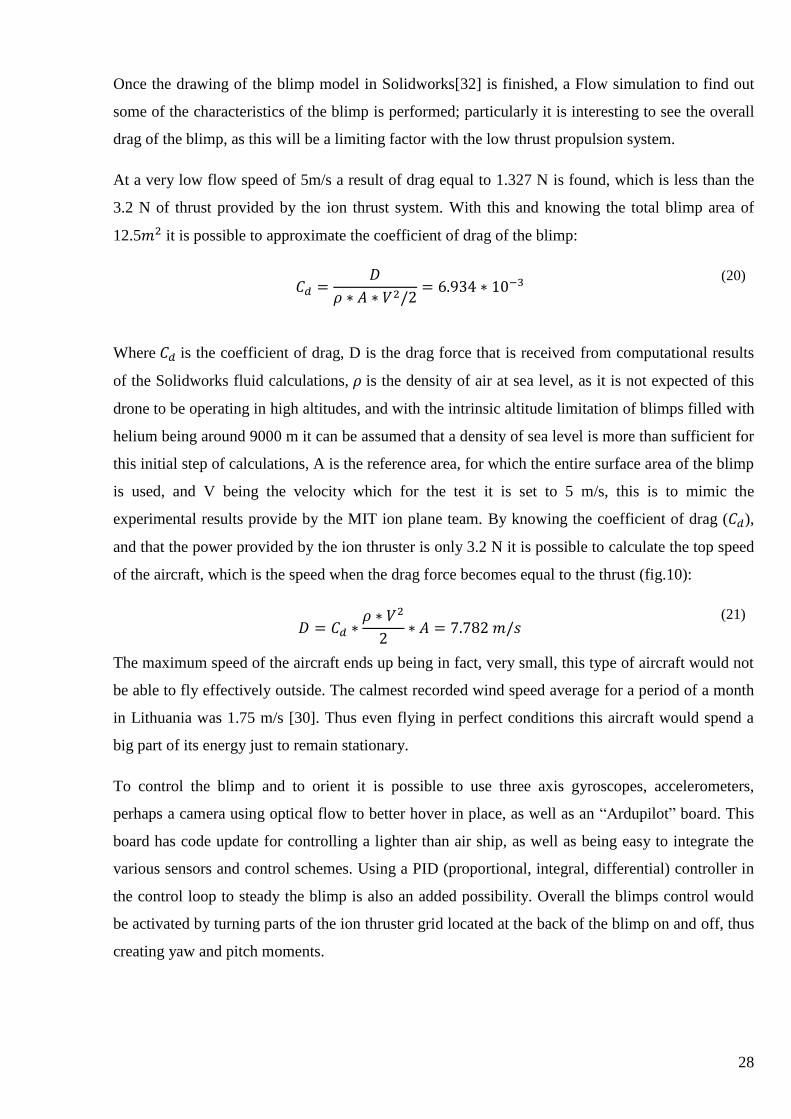
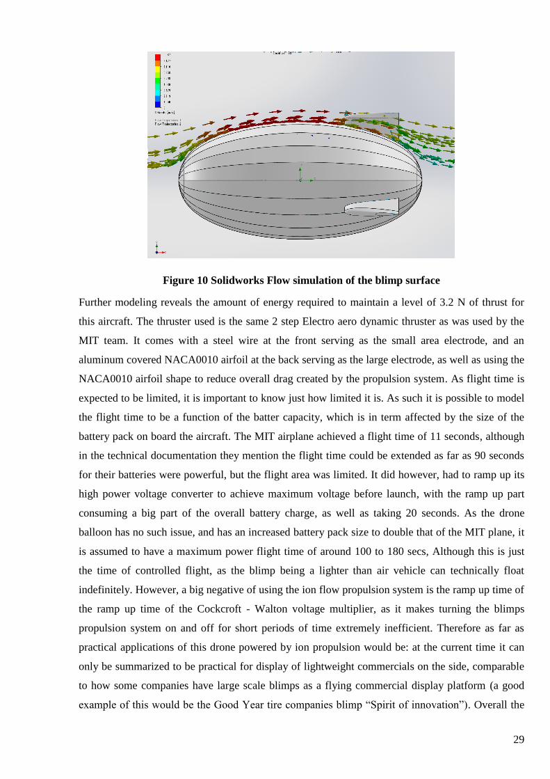
Once the drawing of the blimp model in Solidworks[32] is finished, a Flow simulation to find out
some of the characteristics of the blimp is performed; particularly it is interesting to see the overall
drag of the blimp, as this will be a limiting factor with the low thrust propulsion system.
At a very low flow speed of 5m/s a result of drag equal to 1.327 N is found, which is less than the
3.2 N of thrust provided by the ion thrust system. With this and knowing the total blimp area of
12.5𝑚2 it is possible to approximate the coefficient of drag of the blimp:
𝐶𝑑 =𝐷
𝜌 ∗ 𝐴 ∗ 𝑉2/2= 6.934 ∗ 10−3
(20)
Where 𝐶𝑑 is the coefficient of drag, D is the drag force that is received from computational results
of the Solidworks fluid calculations, 𝜌 is the density of air at sea level, as it is not expected of this
drone to be operating in high altitudes, and with the intrinsic altitude limitation of blimps filled with
helium being around 9000 m it can be assumed that a density of sea level is more than sufficient for
this initial step of calculations, A is the reference area, for which the entire surface area of the blimp
is used, and V being the velocity which for the test it is set to 5 m/s, this is to mimic the
experimental results provide by the MIT ion plane team. By knowing the coefficient of drag (𝐶𝑑),
and that the power provided by the ion thruster is only 3.2 N it is possible to calculate the top speed
of the aircraft, which is the speed when the drag force becomes equal to the thrust (fig.10):
𝐷 = 𝐶𝑑 ∗𝜌 ∗ 𝑉2
2∗ 𝐴 = 7.782 𝑚/𝑠
(21)
The maximum speed of the aircraft ends up being in fact, very small, this type of aircraft would not
be able to fly effectively outside. The calmest recorded wind speed average for a period of a month
in Lithuania was 1.75 m/s [30]. Thus even flying in perfect conditions this aircraft would spend a
big part of its energy just to remain stationary.
To control the blimp and to orient it is possible to use three axis gyroscopes, accelerometers,
perhaps a camera using optical flow to better hover in place, as well as an “Ardupilot” board. This
board has code update for controlling a lighter than air ship, as well as being easy to integrate the
various sensors and control schemes. Using a PID (proportional, integral, differential) controller in
the control loop to steady the blimp is also an added possibility. Overall the blimps control would
be activated by turning parts of the ion thruster grid located at the back of the blimp on and off, thus
creating yaw and pitch moments.
29
Figure 10 Solidworks Flow simulation of the blimp surface
Further modeling reveals the amount of energy required to maintain a level of 3.2 N of thrust for
this aircraft. The thruster used is the same 2 step Electro aero dynamic thruster as was used by the
MIT team. It comes with a steel wire at the front serving as the small area electrode, and an
aluminum covered NACA0010 airfoil at the back serving as the large electrode, as well as using the
NACA0010 airfoil shape to reduce overall drag created by the propulsion system. As flight time is
expected to be limited, it is important to know just how limited it is. As such it is possible to model
the flight time to be a function of the batter capacity, which is in term affected by the size of the
battery pack on board the aircraft. The MIT airplane achieved a flight time of 11 seconds, although
in the technical documentation they mention the flight time could be extended as far as 90 seconds
for their batteries were powerful, but the flight area was limited. It did however, had to ramp up its
high power voltage converter to achieve maximum voltage before launch, with the ramp up part
consuming a big part of the overall battery charge, as well as taking 20 seconds. As the drone
balloon has no such issue, and has an increased battery pack size to double that of the MIT plane, it
is assumed to have a maximum power flight time of around 100 to 180 secs, Although this is just
the time of controlled flight, as the blimp being a lighter than air vehicle can technically float
indefinitely. However, a big negative of using the ion flow propulsion system is the ramp up time of
the ramp up time of the Cockcroft - Walton voltage multiplier, as it makes turning the blimps
propulsion system on and off for short periods of time extremely inefficient. Therefore as far as
practical applications of this drone powered by ion propulsion would be: at the current time it can
only be summarized to be practical for display of lightweight commercials on the side, comparable
to how some companies have large scale blimps as a flying commercial display platform (a good
example of this would be the Good Year tire companies blimp “Spirit of innovation”). Overall the
30
drone would be a novelty, surprising people by silently gliding around the room. It does not have
the mass budget to carry any serious payload, nor does it have the flight time to sustain long term
operation.
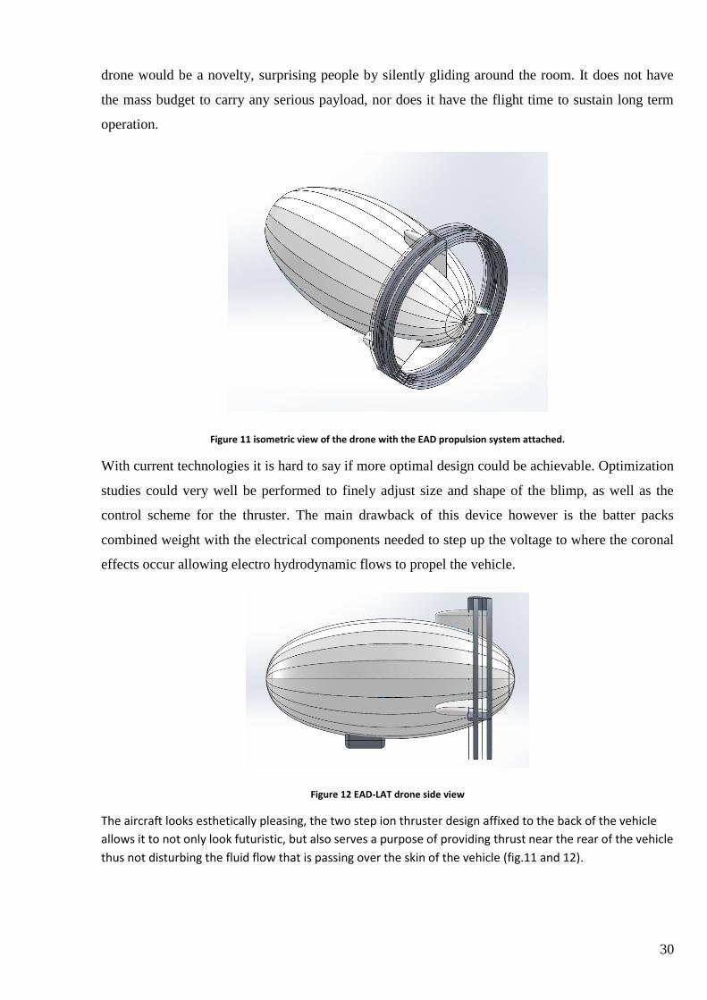
Figure 11 isometric view of the drone with the EAD propulsion system attached.
With current technologies it is hard to say if more optimal design could be achievable. Optimization
studies could very well be performed to finely adjust size and shape of the blimp, as well as the
control scheme for the thruster. The main drawback of this device however is the batter packs
combined weight with the electrical components needed to step up the voltage to where the coronal
effects occur allowing electro hydrodynamic flows to propel the vehicle.
Figure 12 EAD-LAT drone side view
The aircraft looks esthetically pleasing, the two step ion thruster design affixed to the back of the vehicle
allows it to not only look futuristic, but also serves a purpose of providing thrust near the rear of the vehicle
thus not disturbing the fluid flow that is passing over the skin of the vehicle (fig.11 and 12).

31
Structure design and analysis:
A structure to hold the weight of the thruster, as well as to evenly distribute the batter and high
voltage power converter weight along the blimp was designed. The main design constraint was
overall mass, as the blimps weight budget is slim. Rigidity is also an important parameter, thus a
thrust beam structure type was chosen for the main bearing components. The thrusts are made of
balsa wood, as its low density makes it lightweight (fig.13).
Figure 13 a basic structure concept for the drone
For the blimp structure that will hold the skin, a standard structure for lightweight blimps is chosen,
that features ribs and circular members to hold the skin, the design while not ridged, holds the
blimps shape during the process of filling it with helium, this was chose for simplicity [31] (fig. 14).
Figure 14 skin holding structure attached to battery pack and thruster structure
This type of skin holding structure features low rigidity and seems to buckle easily, however due to
the restraints in weight attempts to calculate using this structure will be made.
32
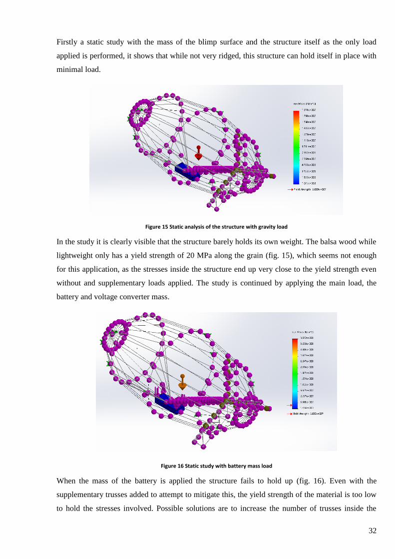
Firstly a static study with the mass of the blimp surface and the structure itself as the only load
applied is performed, it shows that while not very ridged, this structure can hold itself in place with
minimal load.
Figure 15 Static analysis of the structure with gravity load
In the study it is clearly visible that the structure barely holds its own weight. The balsa wood while
lightweight only has a yield strength of 20 MPa along the grain (fig. 15), which seems not enough
for this application, as the stresses inside the structure end up very close to the yield strength even
without and supplementary loads applied. The study is continued by applying the main load, the
battery and voltage converter mass.
Figure 16 Static study with battery mass load
When the mass of the battery is applied the structure fails to hold up (fig. 16). Even with the
supplementary trusses added to attempt to mitigate this, the yield strength of the material is too low
to hold the stresses involved. Possible solutions are to increase the number of trusses inside the
33
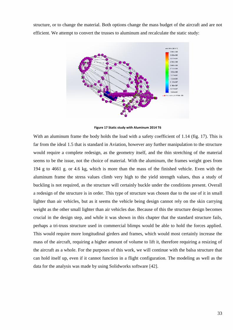
structure, or to change the material. Both options change the mass budget of the aircraft and are not
efficient. We attempt to convert the trusses to aluminum and recalculate the static study:
Figure 17 Static study with Aluminum 2014 T6
With an aluminum frame the body holds the load with a safety coefficient of 1.14 (fig. 17). This is
far from the ideal 1.5 that is standard in Aviation, however any further manipulation to the structure
would require a complete redesign, as the geometry itself, and the thin stretching of the material
seems to be the issue, not the choice of material. With the aluminum, the frames weight goes from
194 g to 4661 g. or 4.6 kg, which is more than the mass of the finished vehicle. Even with the
aluminum frame the stress values climb very high to the yield strength values, thus a study of
buckling is not required, as the structure will certainly buckle under the conditions present. Overall
a redesign of the structure is in order. This type of structure was chosen due to the use of it in small
lighter than air vehicles, but as it seems the vehicle being design cannot rely on the skin carrying
weight as the other small lighter than air vehicles due. Because of this the structure design becomes
crucial in the design step, and while it was shown in this chapter that the standard structure fails,
perhaps a tri-truss structure used in commercial blimps would be able to hold the forces applied.
This would require more longitudinal girders and frames, which would most certainly increase the
mass of the aircraft, requiring a higher amount of volume to lift it, therefore requiring a resizing of
the aircraft as a whole. For the purposes of this work, we will continue with the balsa structure that
can hold itself up, even if it cannot function in a flight configuration. The modeling as well as the
data for the analysis was made by using Solidworks software [42].
34
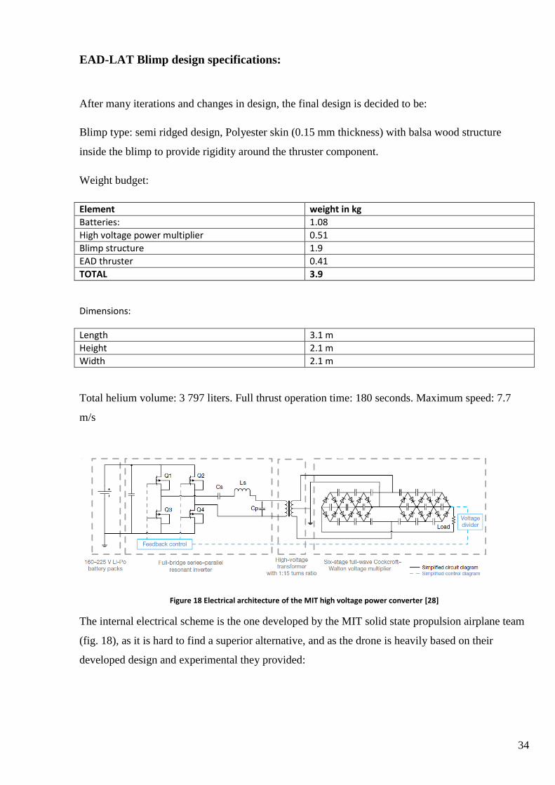
EAD-LAT Blimp design specifications:
After many iterations and changes in design, the final design is decided to be:
Blimp type: semi ridged design, Polyester skin (0.15 mm thickness) with balsa wood structure
inside the blimp to provide rigidity around the thruster component.
Weight budget:
Element weight in kg
Batteries: 1.08
High voltage power multiplier 0.51
Blimp structure 1.9
EAD thruster 0.41
TOTAL 3.9
Dimensions:
Length 3.1 m
Height 2.1 m
Width 2.1 m
Total helium volume: 3 797 liters. Full thrust operation time: 180 seconds. Maximum speed: 7.7
m/s
Figure 18 Electrical architecture of the MIT high voltage power converter [28]
The internal electrical scheme is the one developed by the MIT solid state propulsion airplane team
(fig. 18), as it is hard to find a superior alternative, and as the drone is heavily based on their
developed design and experimental they provided:
35
Conclusion regarding the feasibility of EAD-LAT drone
The final drone design is heavily based on the research and practical experimentation done by the
MIT team I their attempts. By no means can it be said that this drone is practical, as we saw in the
structure analysis, a complete resize or reshape of the structure would be required to comply with
the conditions created by the weights of the elements as well as the limitations of the overall weight
of the aircraft. The main drawback of this type of device is the power consumption is incredibly
high for the thrust provided. While the characteristics of the thrust to power ration of the ion thrust
technology technically can go as high as 50 N/kW in laboratory conditions [28], the real life
experimental data given by the MIT students had the device produce around 3.2 N with power
consumption of 500W, which ends up being around a hundred times less than that. This is added to
by the fact that the thrust density of the technology is limited not only by the room requirement of
the thruster, but also physical limitations such as the electrical breakdown of air [33], meaning the
this technology could not function at higher altitudes, as well as the corona effect can suffer and air
may break down due to weather conditions or change in air quality (possibility of flying over a
flame plume where air is already ionized would cause sparking and damage to the thruster) the
finalized design for the aircraft has a 3 meters length and 2 meters width, with such a size and a
weight of 3.9 kilograms, it still can barely carry enough energy to fly at full thrust for more than a
couple minutes. To compare, a standard propeller driven balloon with the same mass budge for
batteries that was used on the modified batteries as well as the high voltage power converter which
adds up to 1.6 kg would be able to fly for hour with the same amount of thrust provided by a course
pitch propeller. All in all, while it does seem like a novel concept, the drone application of this
technology does not seem practical. For it to become practical not only would it require a much
more efficient way of storing energy, but also a lighter high voltage multiplier, as well as a better
way to apply the voltage to the air, to say provide a higher thrust density way than the current EAD
thruster.

36
Using electric air flow for cooling
As was discussed previously, there are some heavy drawbacks to using Ion thrust. First of all, for
use in any aircraft the necessity to carry heavy batteries, as well as the requirement to convert the
battery DC power to AC using an inverter to change to DC power to AC just so you can apply the
principle of the Cockcroft – Walton multiplier. So the end result is transforming DC power to AC
just to turn it back into DC at the end. This is highly inefficient, as not only due the supplemental
parts weight down the aircraft, but all the conversions of energy end up creating energy losses in the
wires. This however is unavoidable for now, as there is no better way to achieve the high voltages
required for ionization of air molecules in a lightweight and compact way that is needed for
aircrafts. Even if some lightweight way to store AC energy in high voltages would be invented, the
fact that the thrust density and efficiency for the ion thrusts is so low means that it will be likely a
lot less efficient than just the standard brushless motor – propeller combination that popularized
drones in the last couple years. With all of these aspects in consideration, the search of practical
applications for the Ion thrust technology should not limit itself to aerospace, and instead look for
possible applications on the ground.
One such application would be using the flow provided by the ion flow phenomenon to move air for
the purposes of cooling systems. As stated earlier, one of the biggest advantages of ion flow
technology is the lack of noise and moving parts. Noise is a big factor for cooling fans, as noise is a
good representation of quality of parts as well as their durability. A cheaper fan blade will produce
more noise, as well as mechanisms that are aging due to limitations of moving parts with age also
produce excess noise, thus picking the ion flow technology would be a silent solution to both those
problems. No noise and no moving parts.
Small scale EHD devices have been used before as low power coolers for ion spectrometry tools.
This smaller scale type of EHD device requires less voltage to function, only around 1900 V, thus
reducing the requirements for both the power as well as the voltage conversion systems [34].
Another big upgrade is the fact that with ground mounted ion flow producing devices it is possible
to have access to the commonly available 220 V of AC current from the standard outlet. This
reduces the entire side of the electrical voltage multiplier that inverts the direct current into
alternating current (see figure 13), and instead directly taking the 220 V alternating current and
feeding it into the Cockcroft – Walton multiplier to produce the high voltage required. Another
bonus of using the ion flow for cooling instead of thrust is that it can use much heavier materials in
the ion flow production mechanism. Where the aircraft is limited with the weight on board, such as

37
using less efficient diodes for the multiplier or lighter transformers, on ground there is no such
limitations therefore usage of this technology really could be practical.
Finally, perhaps the biggest advantage of all, Ion thruster has no form limitations. A fan has to be
round to turn and produce air movement, as such many computer designers struggle with fitting
them into confined spaces, and flow simulations are required to pick the optimal position where a
fan will fit and still produce enough airflow over the heated components of a computer. Ion flow
thrust has no such limitation, you can fold the wire meshes into any shape or form you like, and it
scales inversely with size, meaning the smaller ion thruster will achieve greater efficiency then the
bigger ones, thus the application for this technology could be in cooling computer components in a
market where the computers and electronic devices are shrinking in size, and fans and cooling
mechanisms are struggling to keep up.
The main drawbacks of using ion flow for ventilation would of course be the power consumption.
As stated before, EAD is extremely inefficient. Further on it will be attempted to compare the
power draw required to power an ion powered cooling device compared to a conventional cooling
device such as a fan.
A paper by N. E. Jewell-Larsen, H. Ran, Y. Zhang, M. Schwiebert and K. A. Honer, shows the
possibility of using an EHD device as a cooling system for a laptop [35], and although a bit
different from the proposed design, it shows the possibility of use of such technology to cool
electronic components for computers. The paper goes into detail about the effectiveness at cooling
the components, but fails to mention the power draw requirements compared to standard cooling
fans.
The paper goes into detail about how modeling the coupled physics and electro hydrodynamics
model yielded results about heat transfer characteristics, when the heat transfer characteristics can
be described as:
𝑞 = ∇ ∗ (−𝑘∇𝑇) + 𝜌𝑖𝑎𝑟𝐶𝑝𝑈 ∗ ∇𝑇 (22)
where q is the heat generation from the corona, k is the thermal conductivity of the medium, T is the
temperature and 𝐶𝑝is the specific heat capacity of air, U is the velocity vector of airflow.
By using the model they created, the team from the University o Washington modeled the heat
transfer characteristics and deemed them acceptable to move on to real live tests by exchanging a
fan in a working laptop with and EHD blower powered by a custom build miniature high voltage
power supply. The EHD cooled laptop operation was surprisingly similar to the laptops operation
with stock fans, the temperature increased by just 10 degrees compared to the standard fan.
38
Although the team continued with the research in building the 2nd
generation EHD cooling system,
it does not appear to be efficient to just exchange the existing computer parts for and EHD cooling
system. One of the main benefits of the EHD cooling as mentioned earlier is the ability to apply the
system to small areas that are inaccessible to conventional fans. One of the major characteristics of
conventional cooling fans called the static pressure is a representation how well the fan performs in
creating a pressure differential to ensure that the airflow will navigate its way through tight
passages to the heated components. While yet another negative is the high voltage power supply
system. The Royer Oscillator used before the voltage multiplier is once again added efficiency
losses. As the fan will be focused on design for a personal computer instead of a laptop, it will have
no problems with the requirement to convert the battery DC current to AC thus skipping a step and
directly going towards the voltage multiplication required to power the cooling agent. As the
voltage requirement to achieve efficient airflow is also less than the before mentioned circuits
40000V, this can also reduce the steps of the voltage multiplier, thus adding simplicity.
While many teams have attempted to design a cooling system using EHD, most seem to be focused
on making ion wind cooling for small devices such as smartphones or laptops, in this work design
of a system for personal computer or server use will be presented. While a big competitor for this
type of device would be liquid cooling systems, as they are also much more silent than conventional
cooling fans, they have the drawbacks of possible failure leading to critical system failure, while the
EHD system failure would lead to a fire, which may seem bad, but in fact most server and computer
users are much more prepared for an electrical fire, and there are ample countermeasures to be
taken against it, than a short that would fry the internals almost instantly.
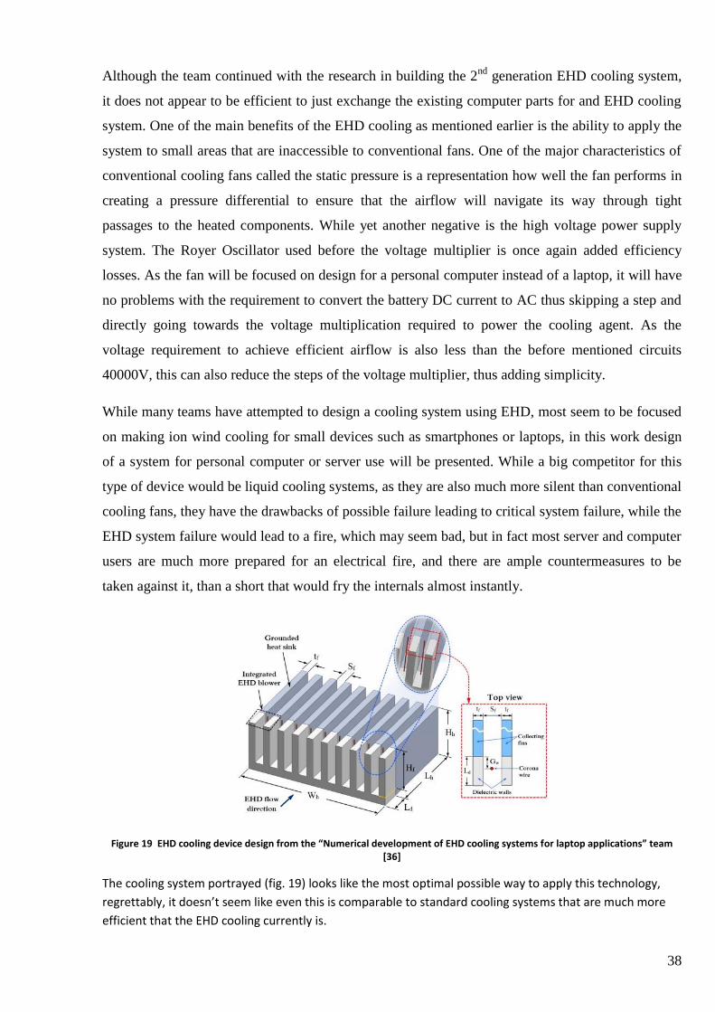
Figure 19 EHD cooling device design from the “Numerical development of EHD cooling systems for laptop applications” team [36]
The cooling system portrayed (fig. 19) looks like the most optimal possible way to apply this technology,
regrettably, it doesn’t seem like even this is comparable to standard cooling systems that are much more
efficient that the EHD cooling currently is.
39
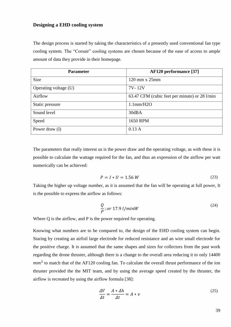
Designing a EHD cooling system
The design process is started by taking the characteristics of a presently used conventional fan type
cooling system. The “Corsair” cooling systems are chosen because of the ease of access to ample
amount of data they provide in their homepage.
Parameter AF120 performance [37]
Size 120 mm x 25mm
Operating voltage (U) 7V- 12V
Airflow 63.47 CFM (cubic feet per minute) or 28 l/min
Static pressure 1.1mm/H2O
Sound level 30dBA
Speed 1650 RPM
Power draw (I) 0.13 A
The parameters that really interest us is the power draw and the operating voltage, as with these it is
possible to calculate the wattage required for the fan, and thus an expression of the airflow per watt
numerically can be achieved:
𝑃 = 𝐼 ∗ 𝑈 = 1.56 𝑊 (23)
Taking the higher up voltage number, as it is assumed that the fan will be operating at full power, It
is the possible to express the airflow as follows:
𝑄
𝑃; 𝑜𝑟 17.9 𝑙/𝑚𝑖𝑛𝑊
(24)
Where Q is the airflow, and P is the power required for operating.
Knowing what numbers are to be compared to, the design of the EHD cooling system can begin.
Staring by creating an airfoil large electrode for reduced resistance and an wire small electrode for
the positive charge. It is assumed that the same shapes and sizes for collectors from the past work
regarding the drone thruster, although there is a change to the overall area reducing it to only 14400
𝑚𝑚2 to match that of the AF120 cooling fan. To calculate the overall thrust performance of the ion
thruster provided the the MIT team, and by using the average speed created by the thruster, the
airflow is recreated by using the airflow formula [38]:
𝛥𝑉
𝛥𝑡=
𝐴 ∗ 𝛥ℎ
𝛥𝑡= 𝐴 ∗ 𝑣
(25)
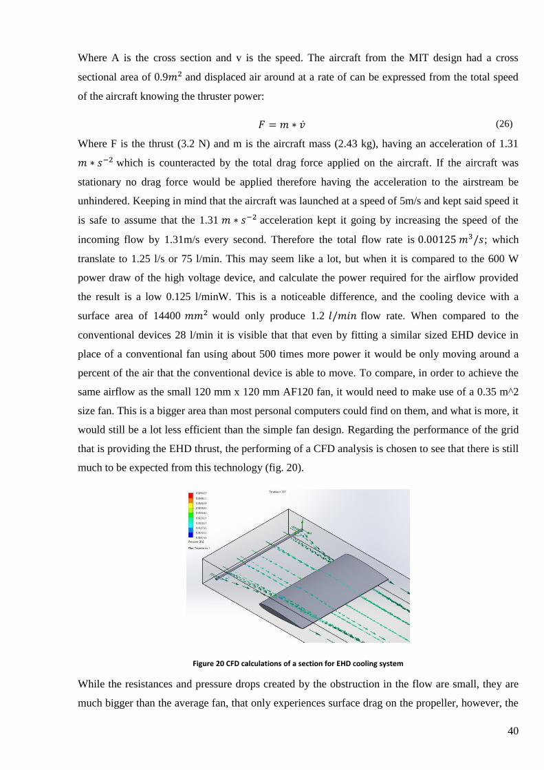
40
Where A is the cross section and v is the speed. The aircraft from the MIT design had a cross
sectional area of 0.9𝑚2 and displaced air around at a rate of can be expressed from the total speed
of the aircraft knowing the thruster power:
𝐹 = 𝑚 ∗ �̇� (26)
Where F is the thrust (3.2 N) and m is the aircraft mass (2.43 kg), having an acceleration of 1.31
𝑚 ∗ 𝑠−2 which is counteracted by the total drag force applied on the aircraft. If the aircraft was
stationary no drag force would be applied therefore having the acceleration to the airstream be
unhindered. Keeping in mind that the aircraft was launched at a speed of 5m/s and kept said speed it
is safe to assume that the 1.31 𝑚 ∗ 𝑠−2 acceleration kept it going by increasing the speed of the
incoming flow by 1.31m/s every second. Therefore the total flow rate is 0.00125 𝑚3/𝑠; which
translate to 1.25 l/s or 75 l/min. This may seem like a lot, but when it is compared to the 600 W
power draw of the high voltage device, and calculate the power required for the airflow provided
the result is a low 0.125 l/minW. This is a noticeable difference, and the cooling device with a
surface area of 14400 𝑚𝑚2 would only produce 1.2 𝑙/𝑚𝑖𝑛 flow rate. When compared to the
conventional devices 28 l/min it is visible that that even by fitting a similar sized EHD device in
place of a conventional fan using about 500 times more power it would be only moving around a
percent of the air that the conventional device is able to move. To compare, in order to achieve the
same airflow as the small 120 mm x 120 mm AF120 fan, it would need to make use of a 0.35 m^2
size fan. This is a bigger area than most personal computers could find on them, and what is more, it
would still be a lot less efficient than the simple fan design. Regarding the performance of the grid
that is providing the EHD thrust, the performing of a CFD analysis is chosen to see that there is still
much to be expected from this technology (fig. 20).
Figure 20 CFD calculations of a section for EHD cooling system
While the resistances and pressure drops created by the obstruction in the flow are small, they are
much bigger than the average fan, that only experiences surface drag on the propeller, however, the
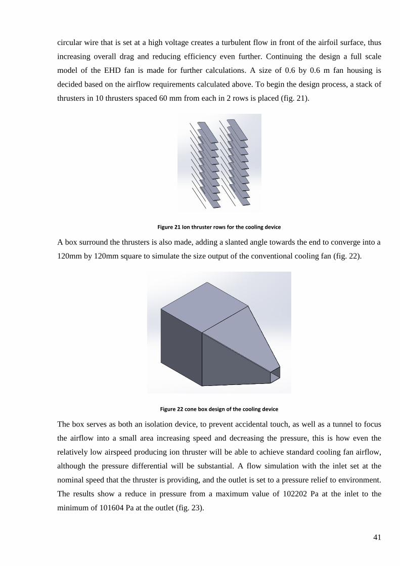
41
circular wire that is set at a high voltage creates a turbulent flow in front of the airfoil surface, thus
increasing overall drag and reducing efficiency even further. Continuing the design a full scale
model of the EHD fan is made for further calculations. A size of 0.6 by 0.6 m fan housing is
decided based on the airflow requirements calculated above. To begin the design process, a stack of
thrusters in 10 thrusters spaced 60 mm from each in 2 rows is placed (fig. 21).
Figure 21 Ion thruster rows for the cooling device
A box surround the thrusters is also made, adding a slanted angle towards the end to converge into a
120mm by 120mm square to simulate the size output of the conventional cooling fan (fig. 22).
Figure 22 cone box design of the cooling device
The box serves as both an isolation device, to prevent accidental touch, as well as a tunnel to focus
the airflow into a small area increasing speed and decreasing the pressure, this is how even the
relatively low airspeed producing ion thruster will be able to achieve standard cooling fan airflow,
although the pressure differential will be substantial. A flow simulation with the inlet set at the
nominal speed that the thruster is providing, and the outlet is set to a pressure relief to environment.
The results show a reduce in pressure from a maximum value of 102202 Pa at the inlet to the
minimum of 101604 Pa at the outlet (fig. 23).
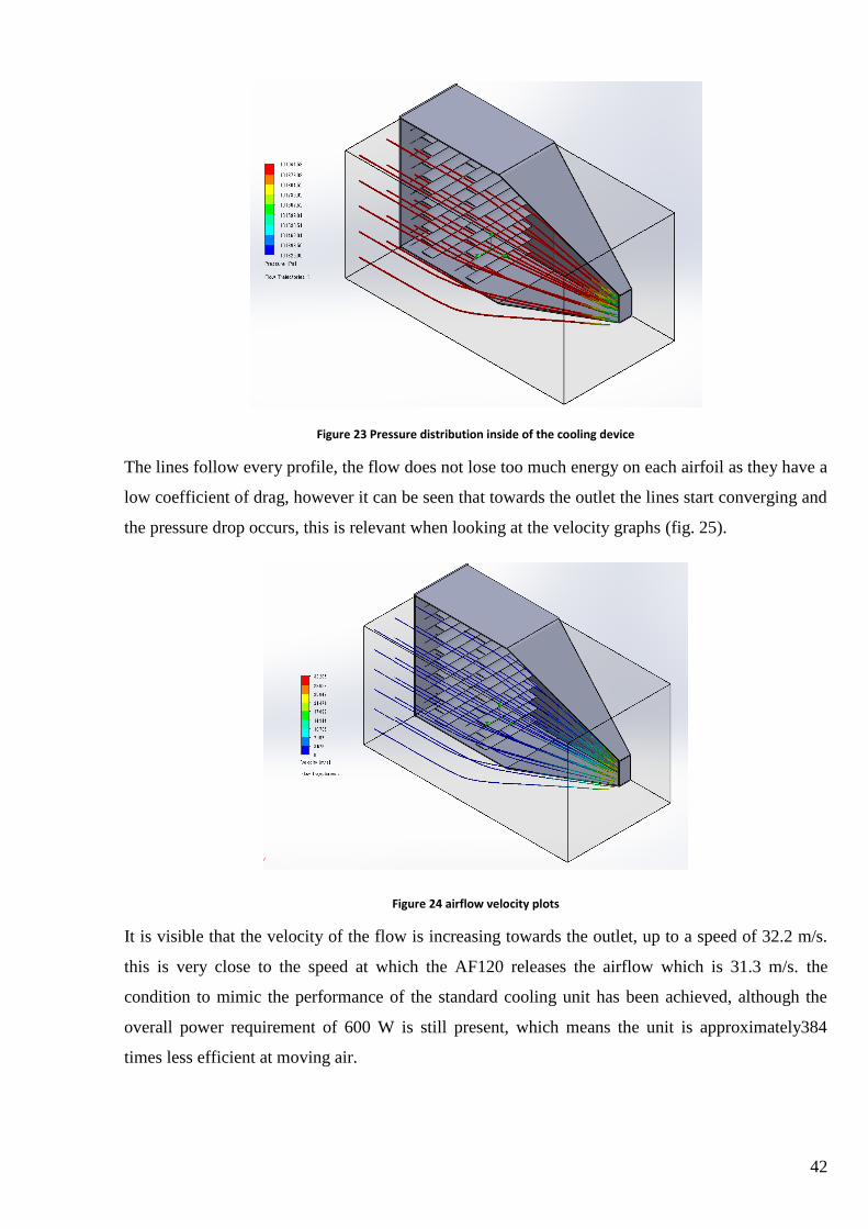
42
Figure 23 Pressure distribution inside of the cooling device
The lines follow every profile, the flow does not lose too much energy on each airfoil as they have a
low coefficient of drag, however it can be seen that towards the outlet the lines start converging and
the pressure drop occurs, this is relevant when looking at the velocity graphs (fig. 25).
Figure 24 airflow velocity plots
It is visible that the velocity of the flow is increasing towards the outlet, up to a speed of 32.2 m/s.
this is very close to the speed at which the AF120 releases the airflow which is 31.3 m/s. the
condition to mimic the performance of the standard cooling unit has been achieved, although the
overall power requirement of 600 W is still present, which means the unit is approximately384
times less efficient at moving air.
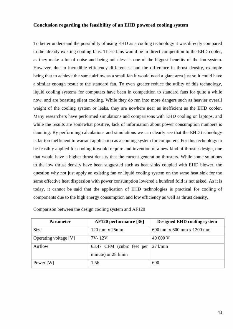
43
Conclusion regarding the feasibility of an EHD powered cooling system
To better understand the possibility of using EHD as a cooling technology it was directly compared
to the already existing cooling fans. These fans would be in direct competition to the EHD cooler,
as they make a lot of noise and being noiseless is one of the biggest benefits of the ion system.
However, due to incredible efficiency differences, and the difference in thrust density, example
being that to achieve the same airflow as a small fan it would need a giant area just so it could have
a similar enough result to the standard fan. To even greater reduce the utility of this technology,
liquid cooling systems for computers have been in competition to standard fans for quite a while
now, and are boasting silent cooling. While they do run into more dangers such as heavier overall
weight of the cooling system or leaks, they are nowhere near as inefficient as the EHD cooler.
Many researchers have performed simulations and comparisons with EHD cooling on laptops, and
while the results are somewhat positive, lack of information about power consumption numbers is
daunting. By performing calculations and simulations we can clearly see that the EHD technology
is far too inefficient to warrant application as a cooling system for computers. For this technology to
be feasibly applied for cooling it would require and invention of a new kind of thruster design, one
that would have a higher thrust density that the current generation thrusters. While some solutions
to the low thrust density have been suggested such as heat sinks coupled with EHD blower, the
question why not just apply an existing fan or liquid cooling system on the same heat sink for the
same effective heat dispersion with power consumption lowered a hundred fold is not asked. As it is
today, it cannot be said that the application of EHD technologies is practical for cooling of
components due to the high energy consumption and low efficiency as well as thrust density.
Comparison between the design cooling system and AF120
Parameter AF120 performance [36] Designed EHD cooling system
Size 120 mm x 25mm 600 mm x 600 mm x 1200 mm
Operating voltage [V] 7V- 12V 40 000 V
Airflow 63.47 CFM (cubic feet per
minute) or 28 l/min
27 l/min
Power [W] 1.56 600
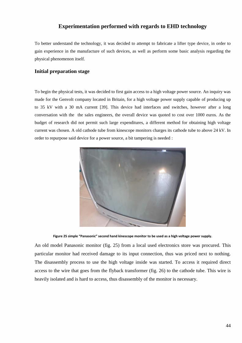
44
Experimentation performed with regards to EHD technology
To better understand the technology, it was decided to attempt to fabricate a lifter type device, in order to
gain experience in the manufacture of such devices, as well as perform some basic analysis regarding the
physical phenomenon itself.
Initial preparation stage
To begin the physical tests, it was decided to first gain access to a high voltage power source. An inquiry was
made for the Genvolt company located in Britain, for a high voltage power supply capable of producing up
to 35 kV with a 30 mA current [39]. This device had interfaces and switches, however after a long
conversation with the the sales engineers, the overall device was quoted to cost over 1000 euros. As the
budget of research did not permit such large expenditures, a different method for obtaining high voltage
current was chosen. A old cathode tube from kinescope monitors charges its cathode tube to above 24 kV. In
order to repurpose said device for a power source, a bit tampering is needed :
Figure 25 simple “Panasonic” second hand kinescope monitor to be used as a high voltage power supply.
An old model Panasonic monitor (fig. 25) from a local used electronics store was procured. This
particular monitor had received damage to its input connection, thus was priced next to nothing.
The disassembly process to use the high voltage inside was started. To access it required direct
access to the wire that goes from the flyback transformer (fig. 26) to the cathode tube. This wire is
heavily isolated and is hard to access, thus disassembly of the monitor is necessary.

45
Figure 26 Flyback transformer
After disassembling and gaining access to the fly back transformer wire pictured on the top, it was ensured
that the grounding wires are in place, and close up the monitor casing was completed [40]. After ensure the
case is closed a couple of tests to make sure that the high voltage is generated and the power supply works
were performed. All appears to be in order. The construction of the lifter begins.
Experimentation stage
During one of the initial tests with a lifter, a short occurred in between the lifters high voltage and
grounded electrodes, causing it to catch fire. It seems that severe underestimation of the voltage provided
by the power source was made, and the dimensions of the distances between the electros not withholding,
a local air breaking corona effect occurred. Not only that, but it appears that the instance short circuited
the power supply, thus putting an end to the tests. While no pictures of this incident were captured, it is
worth stating that these types of experiments are best not performed in a home environment. While it
would be optimal to perform these types of experiments in a laboratory, with proper equipment and the
ability to set voltages and perform testing of shapes of liters, the lack of access to such locals during the
years 2020 and 2021 means improvisation was in order. Once again, it cannot be stressed enough how
luckily no one was injured, but it was enough of a dangerous situation to warrant a cease of practical
experimentation and refocus more on the theoretical side of the research.
46
Conclusions
1. In this project, a study of currently available ion propulsion technologies was made.
Reviewing the papers on this subject showed that the most probable applications of the
technology are aircraft and cooling related.
2. A Lighter than air drone powered by ion thrusters was designed. The drones performance
was compared to that of a conventionally powered similar drone. Efficiency differences are
too high to justify practical application of the technology in the drone field.
3. A EHD powered ventilation system was designed, the system takes up 25 times more area
and is almost 400 times less efficient at moving the same amount of air. Due to the
efficiency difference and size difference the technology cannot be called practical in an
application of large scale computer cooling.
4. Practical tests of the ion propulsion technology have failed. The test did prove the difficulty
of creating stable conditions for the ion thrust to work, as well as displayed the frailty of the
designs most commonly used nowadays.

47
List of references
[1] Mathias Basner, MD, PhD, 1 Charlotte Clark, Anna Hansell, James I. Hileman, Sabine Janssen,
Kevin Shepherd, and Victor Sparrow .”Aviation Noise Impacts: State of the Science”PMC
US Natioanl library of medicine. 2017, March 19th.
[2] ICAO. “ICAO Environment”: https://www.icao.int/environmental-protection/pages/noise.aspx
(2016).
[3] EASA certification of noise levels https://www.easa.europa.eu/domains/environment/easa-
certification-noise-levels
[4] Tech explorist “Shape changing plane wing”: https://www.techexplorist.com/shape-changing-
plane-wing/21967/. 2019, april 1st.
[5] Angus Chen “Silent and Simple Ion Engine Powers a Plane with No Moving Parts” for
Scientific American. https://www.scientificamerican.com/article/silent-and-simple-ion-
engine-powers-a-plane-with-no-moving-parts/?redirect=1 2018 November 21st.
[6] Gad Hayisraeli, “The "Lifter" - The Future's Propulsion System”. 2014
[7] Waluyo Adi Siswanto, Kevin Ngui “Performance of Triangular and Square Ionic Lifter
Systems”
https://www.researchgate.net/publication/216224172_Performance_of_Triangular_and_Squ
are_Ionic_Lifter_Systems 2011
[8] Green car Congress “MIT proof-of-concept demo of ionic wind propulsion for aircraft”
https://www.greencarcongress.com/2018/11/20181122-mitead.html 2018 November 22nd .
[9] Jennifer Chu, “MIT engineers fly first-ever plane with no moving parts”. MIT News.
http://news.mit.edu/2018/first-ionic-wind-plane-no-moving-parts-1121 (2018, November).
[10] Robobees autonimous flying microrobots https://wyss.harvard.edu/technology/robobees-
autonomous-flying-microrobots
[11] Daniel S. Drew and Kristofer S. J. Pister “First Takeoff of a Flying Microrobot With No
Moving Parts”. Berkeley: Berkeley Sensor and Actuator Center, University of California,
Berkeley. Pages 1 - 3 2017
[12] John R. Iwaszko. “Unthethered Ion Propulsion Aircraft” Australia. (2018). Patent No.
2018900472.
48
[13] Francis Hauksbee and the gentle wind “UPS batter center” (2018)
https://www.upsbatterycenter.com/blog/francis-hauksbee-senses-gentle-wind/
[14] Emmanouil D. Fylladitakis, M. P. “Review on the History, Research, and Applications of
Electrodydrodynamics”. Brunel University London:
https://bura.brunel.ac.uk/bitstream/2438/12965/1/Fulltext.pdf 2014, February
[15] Edgar Y. Choueir. “A Critical History of Electric Propulsion: The First 50 Years” (1906–
1956). Princeton University Princeton, New Jerseyi 2016.
[16] Smithsonian Institute Archives. "Robert H. Goddard: American Rocket Pioneer". (2012)
[17] Moshe Einat and Roy Kalderon Ariel University, Ariel, Israel
https://www.researchgate.net/publication/264082208_High_efficiency_Lifter_based_on_the
_Biefeld-Brown_effect pages 1 - 8 2014
[18] M. Tajmar“Biefeld-Brown Effect: Misinterpretation of Corona Wind Phenomena” (2004)
https://www.researchgate.net/publication/245425484_Biefeld-
Brown_Effect_Misinterpretation_of_Corona_Wind_Phenomena
[19] Popular Mechanics. "Major de Seversky's Ion propelled aircraft." 1964
[20] Zoë Webb-Mack " A Brief History of Ion Propulsion NASA 2018
"https://solarsystem.nasa.gov/news/723/a-brief-history-of-ion-propulsion.
[21] Sanghyeon Park. "Ionocraft: Electrohydrodynamic Ion-Propelled Aircraft"
http://large.stanford.edu/courses/2017/ph240/park1/ Standford EDU. 2017, November 4th.
[22] Workshopscience. "Ionocraft project". https://workshopscience.com/ionocraft-project/ 2015.
[23] Kento Masuyama and Steven R. H. Barrett. On the performance of electrohydrodynamic
propulsion. Royal society publishing, 2013
[24] M. Cattani, A. Vannucci, V.G. Souza " Lifter - High voltage plasma levitation device "
http://www.scielo.br/pdf/rbef/v37n3/0102-4744-rbef-37-3-3307.pdf 2015
[25] Ma Chen , Guo Jia , Tang Yuanhui , Lu Rong-de, Ye Bang-jiao.. "Ionization Aerodynamic
Model of the Ionocraft". Hefei, China. 2014
[26] Simscale forums by kcontractor “CFD Investigation of a Bladeless Fan”
https://www.simscale.com/forum/t/cfd-investigation-of-a-bladeless-fan/75023

49
[27] Kwing-So Choi, Timothy Jukes and Richard Whalley “Turbulent boundary-layer control with
plasma actuators” (2011) https://royalsocietypublishing.org/doi/10.1098/rsta.2010.0362
[28] Haofeng Xu, Yiou He, Kieran L. Strobel, Christopher K. Gilmore, Sean P. Kelley, Cooper C.
Hennick, Thomas Sebastian, Mark R. Woolston, David J. Perreault & Steven R. H. Barrett
“Flight of an aeroplane with solid-state propulsion” Letter for Springer Nature limited
[29] Pricing catalogue provided by Balloon Helium.located in the United Kingdom
https://balloonhelium.co.uk/main/pricing
[30] Average weather in Lithuania, statistics provided by:
https://weatherspark.com/y/92695/Average-Weather-in-Vilnius-Lithuania-Year-Round
[31] Airships 101 (2018) https://www.rc-zeppelin.com/what-are-airships-types-facts.html
[32] Daussault Systemes “Solidworks” [computer software] available from:
https://www.solidworks.com/
[33] Subir Ray: “An introduction to high voltage engineering” (2013)
[34] A. O. Ong, A. R. Abramson, and N. C. Tien, “Electrohydrodynamic microfabricated ionic
wind pumps for thermal management applications,” Journal of Heat Transfer, vol. 136, no.
6, p. 061703, 2014.
[35] N. E. Jewell-Larsen, H. Ran, Y. Zhang, M. Schwiebert and K. A. Honer, “Electrohydrodynamic
(EHD) Cooled Laptop” (2009)
[36] Abdulmajeed A.Ramadhan N.KapuraJ.L.Summers H.M.Thompson “Numerical development
of EHD cooling systems for laptop applications (2018)
[37] AF120 technical specifications https://www.corsair.com/de/de/blog/how-to-build-a-pc-selecting-
case-fans
[38] Chastity Hensley “NAFA Guide To Air Filtration Chapter 2 Principles of Air Flow, Air Pressure And Air
Filtration presented by the National Air Filtration Association Fourth.” 2015
[39] Genvolt company 35 kV power supply https://www.genvolt.com/application-
information/5f0c7ef35f2ec/35-kV-Power-Supply
[40] Repurpose a pc monitor into a HV power supply: https://rimstar.org/equip/hvgmon24kv.htm