Embed Size (px)
Citation preview

4
I 1
Study of Plasma Motor Generator (PMG) Tether System for Orbit Reboost
I I I Final Reoort 1 September 1 98 7
I I 1 1 1 I I I I I
https://ntrs.nasa.gov/search.jsp?R=19880003119 2018-05-31T10:01:38+00:00Z

Study of Plasma Motor Generator (PMG) Tether System for Orbit Reboost
Final Report
September 1987
Prepared for:
National Aeronautics and Space Administration Lyndon B. Johnson Space Center Houston, Texas 77058 Contract No. NASS-17751

CONTENTS
THE TRW TETHER STUDY TEAM
1. INTRODUCTION AND STUDY PLAN
2.
3. SELECTION OF HOST SPACECRAFT
4. PLASMA CONTACTOR EQUIPMENT
ELECTRODYNAMIC TETHER THEORY AND TECHNOLOGY
4.1 Plasma Contactor Design
4.2 P1 asma Contactor Requirements
4.3 Plasma Contactor Power Requirements
4.4 Cathode Poisoning
4.5 Plasma Contactor Requirement f o r Host End o f Tether System
5. TETHER MATERIALS, DESIGN AND MANUFACTURE
5.1 Requirements
5.2 Mater ia ls
5.3 Design
5.4 Manufacturing
6. ELECTRONICS
6.1 Power System Conf igurat ion
6.2 Tether Power Supply
6.3 Auxi 1 i ary Power Suppl i es
6.4 Power Equipment Estimates
6.5 Technology Development Issues
7. END MASS AND DEPLOYMENT CONCEPTS
7.1 Concept 1 Host Vehicle Play Out
154-027-87 ii
Page
i v
1-1
2-1
3-1
4-1
4-1
4-2
4-3
4-3
4-5
5-1
5-1
5-1
5-1
5-3
6-1
6-1
6-3
6-5
6-5
6-5
7-1
7-1

8.
9.
10.
11.
12 . 13.
14.
CONTENTS (Cont i wed)
7.2
7.3
7.4
INTEGRATION WITH OMV AND EURECA
COST ESTIMATES
ENVIRONMENTAL CONCERNS
DEPLOYMENT SIMULATIONS
11.1 Deployment I s s u e s
11.2 BEADSIM S i m u l a t i o n s
ENGINEERING DEVELOPMENT PROGRAM
CONCLUSION AND FUTURE WORK
REFERENCES
Concept 2 End Mass P l a y Out
Concept 3 P l a y Out f rom Both Ends
Deployment S c e n a r i o and End Mass
154-027-87 iii
Page
7-1
7-1
7-8
8-1
9-1
10-1
11-1
11-1
11-2
12-1
13-1
14-1

1 I li I I 1 4 E E f I II I 1 II. 8 R E I
THE TRW TETHER STUDY TEAM
Proposal Manager Project Manager Deputy Project Manager Mi ssion Analyst
P1 asma Contactor Equipment
Tether Materials and Design Electronics End Mass, Deployment Concepts and Integration with Spacecraft Cost Estimates Environmental Concerns Deployment Simulations
David L. Younkin Dr. Neal D. Hulkower H. Jack Melcher Christine Coffer Raasch Dr. Dale Stuart Dr. Paul Wilbur, Colorado State University Dr. R. P. S t i l lwel l Dr. Ronald C. Rossi John Biess
Robert Strommer Mark 3. Adams N. John Stevens J. A. Carroll, Energy Sciences Laboratori es
154-027-87 i v

FINAL REPORT PMG TETHER STUDY 1. INTRODUCTION AND STUDY PLAN
The emerging technology of electrodynamic te thers promises substantial benefits f o r America's space program. To date, however, the f eas ib i l i t y and advantages of integrating tethers with spacecraft remain largely i n the realm of theory. NASA's study of Plasma Motor Generator (PMG) te ther systems fo r o rb i t reshoot is an important step i n establishing the val idi ty of this applied technology.
T h i s report describes the resu l t s of a study by TRW f o r NASA on a 2 kW PMG t e the r system t o be used fo r orb i t reboost. opportunity t o advance the s t a t e of the ar t of a new space technology. Successful demonstration should lead t o the inclusion of such a system on future spacecraft as an integral part of the propulsion and e lec t r ica l power systems.
T h i s study represented an
The objectives o f the study were to:
1. Develop a viable 2 kW PMG engineering design model
2.
3.
Select representative missions and spacecraft from current mission models fo r possible inclusion of a PMG te ther system
Perform studies t o assess the impact of integrating the PMG te ther system w i t h the candidate spacecraft
4. Study the operations of the integrated systems
5. Produce performance figures as a basis of selecting a single m i ssi on and spacecraft
6. Create an engineering design and development plan fo r the PMG t e the r system tai lored t o the selected mission.
Figure 1-1 is the study plan fo r these ac t iv i t i e s .
154-027-87 1-1

I - 4
- > - - - - - - 0 i 0 w z 0 w
1-2

2. ELECTRODYNAMIC TETHER THEORY AND TECHNOLOGY
In this section, simple explanations of tether theory and relevant technology are presented as the basis of understanding the PMG t e ther system
Consider a conducting te ther wire of length - L c u t t i n g across the geomagnetic f i e ld - B w i t h orbi ta l velocity - v. An open-circuit potential difference V i s generated between the ends of the te ther given by
T h i s potential difference induces a current i t o flow through the te ther causing an electrodynamic force given by
T h i s force i s opposite t o the velocity, producing power a t the expense o f orbi ta l energy.
The te ther can also be used fo r o rb i t reboost by reversing the current flow i n the te ther . spacecraft t o overcome the induced current so tha t a net current flows i n the reverse direction, an accelerating force will be produced causing an a l t i t ude increase a t the expense of e lec t r ica l power from the spacecraft.
For the te ther t o function as a power generator o r an o rb i t reboost motor, a current loop must be completed through the ambient plasma of the ionosphere. The connection between the te ther ends and the ionsphere i s made via a plasma contactor. The baseline contactor design i s a hollow cathode. electron guns because of weight, size and power advantages. The tether concept using a hollow cathode as the plasma contactor is referred t o as the PMG te ther system.
I f enough current i s supplied to the te ther by a
I t is preferred over the al ternat lves of passive collectors and
The hollow cathode works by flowing argon o r xenon through the cathode tube. The external heater causes thermionic electron emission from the inser t w h i c h i n turn creates a plasma within the cathode tube. The anode
154-027-87 2- 1

draws electrons from the cathode creating a plasma ball outside the cathode tube. The plasma ball functions as the plasma contactor, supplying whatever charged species i s required to complete the current loop.
Tether technology includes the tether materi a1 , storage and deployment mechanisms, tether control and stability, and dynamic interaction with the spacecraft. The recommendations for these mechanisms and findings on these issues constitute the major portion of this report.
I m n 1 mt I 1 I I; 1 I 1 1 I I 1 1 4 154-027-87
e 2-2

3. SELECTION OF HOST SPACECRAFT
The search f o r sui table spacecraft t o host the f l i g h t demonstration of the PMG t e the r system began with the mission models of NASA Johnson Space Center, the Space Assembly, Maintenance and Servicing Study (SAMSS) and the Orbiting Maneuvering Vehicle (OMV) program. Many missions were eliminated because the orbits did not cross geomagnetic f i e l d l ines , f o r example those flying i n polar orbi ts . Others were eliminated because the plasma and magnetic f i e ld are too weak, for example those i n geosynchronous orbi ts . Experiments attached t o the Space Station o r t o the Shuttle were discarded because of the lack of need fo r orb i t reboost. The remaining missions were categorized in to ten groups based on host spacecraft and function as required by the statement of work fo r more careful examination. l i s t s these candidates.
Table 3-1
These candidate spacecraft and missions were reduced t o four; OMV, ISF, Spartan and RPDP a f t e r additional information was gathered and more s t r ingent c r i t e r i a applied. These c r i t e r i a included launch before 1998, the need f o r o rb i t reboost, the design of the host spacecraft being a t a stage conducive t o the integration of the te ther system, ample power, and not having a stringent po in t ing accuracy requirement. summarizes the missions rejected and the reasons.
Figure 3-1
In addition t o the four missions l i s t ed above, the European Retrievable Carrier (EURECA) was included i n the final l i s t because of i t s highly desirable character is t ics . These a re mission length, ample power, design as an all-purpose payload host, and early avai labi l i ty . purposes of t h i s study, two of the f ive spacecraft, OMV and EURECA, were selected.
For the
3-1
I I i 1 8 1 I B I 1 I 1 I 1 I I 1 D e
Table 3-1. Candidate List for Host of Flight Demonstration
Spacecraft/Functi on Category
Space Station
Space Telescope
Earth Observation
Upper Atmosphere P1 atform
Power Supply
Industri a1
Li f e Sci ences
Technology Demonstration
Mi ssi on (s) _ _ ~ ~ ~ ~
Tethered Electrodynamic Power
Large Depl oyabl e Ref 1 ector P1 anetary Mu1 ti spectral Telescope
Microwave Remote Sensing Geology Sate1 1 i te
Recoverable Plasma Diagnostic Package (RPDP) Space Station Coorbiting Platform Explorer Astronomlcal Platform Systems Technology
A1 1
Industrial Space Faci 1 i ty (ISF) Space Processing for Advanced Materials Commercial Space Processing Materials Processing Lab
CELSS Biotechnology
Orbi ti ng Maneuvering Vehi cl e (OMV) Spartan
154-027-87 3-2
x x
X X X K x
x x
x x
x x x x x
a 0
I2 4 w u
y1 d s a w
I- U w 3: w u
a
3-3
U aJ c, W aJ .r, W
c, 9- (21 L V aJ V CCI P v)
U E (21
v) E 0
v) v)
E W c, (21 U U E (21 0
a
c
c
c
. rl
I m W L J m I& c

4. PLASMA CONTACTOR EQUIPMENT
Early work on the concept of a PMG te ther system i s contained i n References 1 and 2. This design served as a s ta r t ing po in t fo r this study.
T h i s section will discuss the plasma contactor requirements f o r the PMG Tether System. The topics will include the power and mass require- ments, the plasma contactor configuration and the requirement fo r a contactor a t the host end of the system. te ther materials and design and electronics a re discussed i n de ta i l .
In Sections 5 and 6, the
4.1 PLASMA CONTACTOR DESIGN
The plasma contactor design i s based on the hollow cathode design tha t has been used i n plasma contactor research (References 3 and 4) . The design i s shown schematically i n Figure 4-1. The device consists of a tantalum tube electron beam welded to a thoriated tungsten o r i f i ce plate. Located w i t h i n the hollow cathode is a t h i n rolled tantalum f o i l inser t which is e lec t r ica l ly connected t o the cathode tube. The inner surface o f the inser t i s coated with a low work function material (barium and strontium carbonates) . Wrapped around the cathode tube i s heater wire, The heater is composed of a res i s t ive wire filment insulated from the tantalum casing. A radiation shield of tantalum fo i l is wrapped around the heater wire. Several millimeters downstream of the cathode is a disc anode (called a keeper by those familiar with hollow cathode technology) used to i n i t i a t e and sustain hollow cathode operation.
For a f l i g h t design the tantalum fo i l insert should be replaced by a
hollow porous tungsten plug. Experience w i t h f o i l inserts has shown t h a t the fo i l deteriorates, becoming br i t t le and flaking a f t e r short periods. This substi tution will resul t i n a s l i gh t increase i n the hollow cathode power requirement.
The expellant gas recommended is xenon. The use of xenon will increase both the l ifetime and operating efficiency o f the contactor over t h a t of argon, an a l ternate gas considered as an expellant.
154-027-87 4- 1

0.64 cm OIAMETER TANTALUM TUBE
. . I 11.6mm HEATER --- - - - ---
A 1 V A N O D E W I R E 1
0 0 0 0 0 INSERT,
- 2 mm EXPELLANT- I '
TUNGSEN 0.76 mm ORIFICE SUPPLY RADIATION ANODE
SHIELD A POWER T SUPPLY
TIP
Figure 4-1. Schematic of Hollow Cathode
4.2 PLASMA CONTACTOR REQUIREMENTS
The plasma contactor equipment requirements include the hollow cathode power supplies as well as expellant storage and control hardware. The hollow cathode will require two power supplies, the heater and anode supplies, as shown i n Figure 4-1. In addi t ion , a high pressure tank (4200 p s i ) i s required fo r storage and a redundant pressure regulated system i s needed f o r expellant flow control. A heater will be required f o r the storage t a n k t o maintain the expellant above i t s c r i t i ca l temperature 1 7 O C for xenon). A redundant plasma contactor assembly is recommended fo r re1 i abi 1 i ty .
The expellant supply system weight and mass estimates a re given i n Table 4-1. The mass of the hardware is based on space-qualified hardware (References 5 and 6). The expellant storage tanks a re spherical w i t h a diameter o f 35 cm. The weight o f the xenon i s based on a flow ra te o f 5 sccm. The weight and mass estimates for the hollow cathode power supplies a re given i n the section on electronics. The s i z i n g of the expellant
154-027-87 4-2

Tab1 e 4-1. Weight and Mass Estimates f o r Expel 1 ant Supply System (per contactor)
Expel 1 ant tankage
Xenon supply (1 year)
Regulation system
Wei h t Mass
6.0 3 .O
31.0 14.0
8.5 3.9
(1 by (kg)
tankage heater supply must await a thermal analysis. hollow cathode i t s e l f is negligible. The hollow cathode is approximately 7 cm long.
The mass of the
4.3 PLASMA CONTACTOR POWER REQUIREMENTS
The contactor power requirements includes the heater power, the power t o operate the hollow cathode discharge (anode power) and the power lost i n the contactor sheath potential drop (supplied by the te ther) . The power requirements are based on the plasma contactor performance curve shown i n Figure 4-2 (Reference 3). The total power requirement is 127 W. A breakdown of the power requirements i s given i n Table 4-2. Similar performance figures have been achieved w i t h the s l igh t ly d i f fe ren t cathode design from Johnson Space Center (JSC).
The power estimate assumed that a plasma contactor i s required a t both ends of the tether system. The val idi ty of this assumption will be demonstrated l a t e r i n t h i s section.
4.4 CATHODE POISONING
Once a cathode has been operating, the rare-earth oxide coating on the tnner surface of the insert i s susceptible t o contamination by oxygen and moisture. A t operational a l t i tudes , contamination should not be a problem due t o the low concentration of oxygen and the expellant flow. The concern is over cathode poisoning occurring between the cathode ground t e s t s and launch. considerably more heater power (Reference 7) and i s therefore not
Using a hollow cathode without the oxide coating would require
154-027-87 4-3

ELECTRON @YLssION CURREYT
+A 9 Q.BA V m - 4 TO 14V - 2.f . roa (Xc)
9 3.5 8 lod TORR 12 cm DIA ANODE
ELECTRON @YLssION CURREYT
-640
- 250
CONTACTOR ANODE TO PtASMA?OTENTIAL DlFF (VI so 100 150
I I
t
I
-TRANSITION TO IGNITED MODE
-250 -
-500-
-7w -
-1mo - Figure 4-2. Conventional Contactor Performance
-1mo l-
Figure 4-2. Conventional Contactor Performance
4-4

Tab1 e 4-2. P1 asma Contactor Power Requirement
15 4
I 60
Watts r- I 1 A electron emission
Heater power Discharge power Sheath power
1 A electron collection
Heater power Discharge power Sheath power
15 13 20
suggested. A control led enclosure preventing contamination of the oxide between the ground t e s t and launch is recommended.
Another approach would be the use of an internal s t a r t e r electrode. The s t a r t e r electrode would i n i t i a t e a discharge within the cathode tube (Reference 7) . Once the discharge has been s ta r ted , the s t a r t e r electrode would be turned off . require a more complex contactor w i t h an additional power supply. This approach has been suggested fo r other appl ications of hollow cathodes
The electrode would allow eas ie r start-up bu t would
(Reference 8) and is presently employed in the plasma contactor research a t JSC.
4.5 PLASMA CONTACTOR REQUIREMENT FOR HOST END OF TETHER SYSTEM
I t was assumed when estimating the contactor power requirements t ha t a contactor would be required on both ends of the tether system. This analysis validated tha t assumption. A plasma contactor on the host end i s needed i f the spacecraft structure cannot col lect from the environment the required current of 1 A required by the te ther system. The current collection is dependent on the plasma environment, spacecraft velocity and spacecraft s t ructure potential , re la t ive t o the ionsphere.
The plasma environment is one of the determining parameters i n calculating the current collection. Since the te ther system will f l y in low earth orb i t (LEO), the analysis was confined t o a l t i tudes between 300
154-027-87 4-5

and 1000 kin. The plasma parameters (density, temperature, and ion species) vary with a l t i t ude as well as with time of day. time of day bu t a lso w i t h the dominant ion species. A t night hydrogen is the major ion species over these altitudes, while dur ing the day atomic oxygen t s the major ion species.
The plasma parameters used were obtained from Reference 9.
The ion density not only varies w i t h
As the te ther system is reversible, the spacecraft end must be able t o co l lec t both electron and ion currents. The thermal current density measure is A/m2 and fo r electrons is three orders of magnitude greater than ions. As such, the ion collection capabili ty of the spacecraft s t ructure is much lower, and i s therefore the limiting collection process. Only the ion collection was calculated fo r this analysis.
The ion collection is dependent on the spacecraft s t ructure potential. In the 2 kW system, a potential different of 2 kV will ex i s t between the spacecraft host and the te ther end mass. How the host potential will equi 1 i brate w i t h the plasma would require another analysis. calculations, the two extreme points, 0 and 2 kV, was considered.
A t zero potential , the ion collection will be dominated by ram collection since the ram flux is 6 t o 35 times greater than the thermal flux. spacecraft velocity. The required surface area fo r one ampere of ram ion collection i s shown i n Figure 4-3(a).
For these
The ram ion current collection is dependent on ion density and
A t 2 kV s t ructure potential , the ion collection will be predominately thermal ions and will be controlled by sheath effects . accurate model of ion collection a t h i g h voltages has not been developed. An empirical model of the ion collection by a plate based on experiments on large structures (Reference 10) has been used t o calculate the ion collection. The predicted spacecraft structure area required t o co l lec t one ampere of thermal ion current i s shown i n Figure 4-3(b).
To da t e , an
The calculations of the surface area of the host spacecraft s t ructure required fo r the ion collection demonstrated t h a t the required area i s so large tha t i t makes this collection scheme impractical.
154-027-87 4-6

154-027-87
E d d a a
v)
w
w Y LL a 3 v)
(3 z 0 w -I -I
F
8
H d 4
a
a
v)
w K
w 0 U K 3 v)
13 2
u w -I -I 0 0
F
(A) RAM ION COLLECTION
HYDROGEN ION 105
- - - - -
10s ION COLLECTION - - - - - -
I I I
'03200 400 600 800 1 000 ALTITUDE, KM
(B) THERMAL ION COLLECTION 2 KV SURFACE
400
ATOMIC OXYGEN
300 -
200 - HYDROGEN ION COLLECT1 ON 100 -
0 * I I
200 400 600 800 1000 ALTITUDE, KM
Figure 4-3(a) (b). Surface Area Required for 1 A of Current Collection
4-7

5. TETHER MATERIALS, DESIGN AND MANUFACTURE
In t h i s section, the requirements fo r the tether and a detailed design addressing these requirements including the materials for construction and the engineering configuration are presented. Additionally, a report is given on the manufacturing of 1100 f t (335 m) of cable tha t will allow ground-based evaluation of cable performance.
5.1 REQUIREMENTS
The primary components of the te ther consists of two elements, a f lexible wire w i t h low electr ical r e s i s t i v i ty and an insulating sheath tha t prevents e lec t r ica l discharge and protects the wire from erosive o r corrosive environments. Additional requirements fo r the wire include low mass, benign responsi veness t o nonrigid body dynamics and f l exi b i 1 i ty. The insulation material must be able t o avoid degradation from atomic oxygen attack i n LEO and have suff ic ient durabili ty t o sustain mechanical handling in deployment and retrieval operations without suffering damage.
5 . 2 MATERIALS
Only aluminum among low re s i s t i v i ty conductors has the appropriate combination of high mass conductivity and mechanical properties suitable for the te ther conductor. durabili ty, the aluminum should be f ine stranded wire tha t minimizes permanent deformation while undergoing dynamic gyratory deployment, retrieval and nonrigid body motions.
To provide the required f l ex ib i l i t y and fatigue
The insulation material must be restr ic ted t o the fluoroplastics t o provide both suitable d ie lec t r ic strength and atomic oxygen protection i n LEO. Among the fluoroplastics, fluorinated ethylene propylene (FEP) has the desired properties and i s state of the art as cable insulation.
5.3 DESIGN
In addition t o the primary components required fo r the e lec t r ica l performance of the tether, other materials of construction are necessary t o provide strength and abrasion resistance i n design configuration of the tether is shown Kevlar core provides strength t o the te ther
154-027-87 5-1
manufacture and use. The i n Figure 5-1. The 0.5 mm in use as well as strength t o

v) c z Ly L 0
0 u k
E 0
c, I L CT,
E 0 V
*-
a
z
154-027-87 5-2

the cable during manufacture. The aluminum conductor represents the major mass of the cable and dominates the mechanical response of the cable. provide appropriate torsional balance, the strands of the aluminum are divided i n approximately equivalent proportions and counter wound about the Kevlar core. A coating of FEP insulation is appl ied t o the aluminum conductor and overwrapped w i t h glass fiber braid which is subsequently impregnated w i t h FEP. The glass f ibe r braid provides both an abrasion resistant outer coating and an additional strength component t o the cable.
To
5.4 MANUFACTURING
In order t o evaluate the te ther design, a purchase order was placed w i t h Brand-Rex Cable Systems Division of BRIntec Corporation, Willimantic, Connecticut t o fabricate 1000 f t (305 m) of cable as designed. However, constraints of time and manufacturing l imitations on a small batch order required a l te ra t ions t o the design. The cable actually manufactured i s shown i n Figure 5-2. The aluminum conductor consists of s ix strands o f No. 24 AWG wire wrapped around the Kevlar core and an outer layer of f i f teen strands of No. 26 AWG wire cowound about the inner layer. Two mil t h i c k Kapton tape is counter wound about the conductor and 10 mils of FEP are extruded onto the Kapton. Major changes t o the design a re the addition o f Kapton and the elimination of the glass braid.
The Kapton tape was introduced t o protect the aluminum conductor from oxidation as i t passed through the preheat furnace and hot FEP extrusion die. The glass braid contributed abrasion resistance and strength; however, these properties were redundant i n the design. The Kevlar core provides suf f ic ien t strength t o the cable t o meet the te ther requirements and the FEP insulation has suff ic ient toughness t o withstand the single deployment and t e s t sequence planned for the tether demonstration f l i g h t test.
I f the performance evaluations of the t e s t cable support these contentions, the a1 ternat i ve design w i 11 contribute two important advantges t o the tether design configuration. The elimination o f the glass braid represents a s ignif icant weight saving and the construction of the cable would use s t a t e o f the art process technology t h a t will be reflected i n a lower cost than the original design.
154-027-87 5-3
I
0
/ a /
W % a z uo 9 a- N
O W
Y- N
f
i z 0 E E s
c
5-4

6. ELECTRONICS
Since 1969, TRW has had an advanced power system and power electronics development program i n support of the future multikilowatt space missions. Extensive power electronics development has been performed on the 30 cm Mercury Ion Thruster Electric Propulsion Power Processing Equipment fo r NASA Lewis Research Center. Much of this thruster electronics technical background can be d i rec t ly applied t o the PMG Tether System Program which w i 11 greatly reduce technical, cost and schedule risks. The power electronics work will be performed by the Power Electronics Research Center i n the Electrical Systems Operation.
The Power Electronics Research Center is s taffed by senior power electronics design engineers specializing i n space conditioning design development, packaging and system integration.
The following subsections br ief ly discuss the conceptual power system configuration, the power electronics designs f o r the different power supplies, an estimate of the power system characteristics and a brief discussion of the necessary technology programs t o support the PMG Tether System Program.
6.1 POWER SYSTEM CONFIGURATION
Figure 6-1 displays the te ther power system block diagram. The system includes the power electronics on board the main o r host spacecraft, on the t e the r end mass and the interconnecting te ther cable.
The host spacecraft solar array and battery i s used as the prime power source f o r the PMG te ther system. A 100 VDC power system i s assumed b u t a 28 VDC bus could easi ly be used.
The power system includes a te ther power supply rated a t 2 t o 4 kW, an anode power supply rated a t 20 W and a heater power supply rated a t 100 W.
The end mass assembly contains a small so la r array battery auxiliary power source operating a t 12 V which is used primarily t o s t a r t the end mass electronics. A charger power supply i s used t o t a p a portion o f the t e the r power cable t o charge the end mass battery and t o operate the end
154-027-87 6-1
6-2
t U LT
c m
L Q, c c, Q,
t-

a
mass power electronics. Both anode and heater supplies are used t o operate the end mass plasma contactor.
All o f the power supplies i n the PMG tether system use the current source c i r cu i t topology t h a t can operate i n short or arc condition without any overcurrent s t r e s s condition on the power electronic components. Then electronics have been fu l ly developed and flown on f l i g h t programs w i t h demonstrated re1 i ab i l i t y .
6.2 TETHER POWER SUPPLY
A bidirectional DC/DC converter is proposed fo r the high voltage te ther power supply (Figure 6-2). Bidirectional i ty i s required t o del i ver current t o the tether system t o provide orb i t boost capabili ty o r t o absorb power from the te ther system t o provide o rb i t braking capability. The low voltage section (host bus voltage) uses power t rans is tors as the switching elements i n the normal power flow operation. High voltage triodes a re used as switching elements (due t o 2 kV requirement) during the reverse power flow operation. L2 shorted by the relay. During reverse power flow inductor L2 is used.
Inductor L 1 is used during normal operation w i t h inductor
The normal power operation cycle will be br ie f ly discussed. Assume t rans is tors Q1 and Q2 are turned on, DC power is allowed t o be stored i n inductor L 1 and delivered to the power transformer T1. When the control electronics has determined tha t suff ic ient energy has been delivered by the DC source, transistor Q1 i s turned of f , and the energy stored i n inductor L1 i s allowed t o flow into the power transformer through t rans is tor Q2 and diode CR4.
On the next half cycle t rans is tors Q3, 44 and diode CR6 perform a similar sequence t o maintain output vol tage/current regulation.
The output AC voltage of the power transformer is rec t i f ied by diodes CRA, CRB, CRC and CRD. During reverse power flow, inductor L2 is switched i n and t r iodes VA and Vg and diode CRE act i n a similar manner t o transistor Q1 and Q2 and diode CR5 during normal power flow. Triodes Vc and VD and diode CRF operate on this alternate half cycle. Diodes C R 1 , C R 2 , CR3 and CR4 r ec t i f i e s the low voltage AC winding voltage w i t h reverse energy giving into the host power system battery.
154-027-87 6-3

P P =1 v)
L
L W c c, W c
6-4

I I I I I I I I I 1 I 1 I I I 8 I I I
6.3 AUXILIARY POWER SUPPLIES
Conventional current source dc/dc converters are used fo r the anode and heater power supplies. Figure 6-3 shows the power stage c i r cu i t topology fo r a 100 VDC i n p u t and Figure 6-4 displays the power stage circuit topology fo r 12 t o 28 VDC bus voltage.
T h i s same basic power stage i s used for the end mass charger where power from the te ther cable i s used as the i n p u t power source and the o u t p u t is used f o r the 12 VDC bus power and battery charging.
6.4 POWER EQUIPMENT ESTIMATES
Table 6-1 provides an engineering estimate of weight, size, efficiency and losses fo r the power equipment required fo r the PMG te ther system. Both main spacecraft and te ther end mass devices are estimated. The weight, size and efficiency data are derived from existing f l i gh t hardware except f o r the te ther power supply. The solar array i s estimated as body mounted c e l l s where the total effective area is 2 f t2 .
6.5 TECHNOLOGY DEVELOPMENT ISSUES
Most of the power electronics component, c i r cu i t and packaging technology has been developed and are presently available fo r a l l of the 1 ow vol tage DC/DC power suppl i es. The ser ies inductor converter ci rcui t topology development for each power supply is completed. The 2 kW power rating development was performed under a TRW IRAD. While 2 kV o u t p u t voltage a t 2 kW has not been demonstrated, 10 kV a t 500 W has flown on the Communication Technology S a t e l l i t e (CTS) and 1 kV a t 2 kW has been demonstrated fo r ion e l ec t r i c propulsion. The keeper supply electronics was developed fo r the Ion Electric Propulsion Program as well. A 1 imited amount of development work is required fo r the bidirectional te ther power supply and for the te ther t o battery charger power supply.
There are two development issues fo r the te ther power supply, the application o f power triodes as converter switches operating a t 2 t o 4 kV and the associated t r iode heater losses and t r iode saturated drop. The bidirectional circuit operation has been demonstrated on the space s ta t ion advanced development program fo r NASA Lewis Research Center.
154-027-87 6-5

I ~I I I
~B I I I I I I I I I I I I I I
MAIN SPACECRAFT DC/DC CONVERTER (100 V DC INPUT)
Figure 6-3. Anode/Heater Power Supply Schematic
TETHER DC/DC CONVERTER LOW VOLTAGE INPUT (12 V DC)
+ - 12 V DC
- E OUTPUT T 0
Figure 6-4. Charger-Anode-Heater Power Supply Schematic
6-6

I I I I I 1 I I I I I i I I I I I I I
~~~ ~~ ~~~~~~~~
Table 6-1. Estimates for the Power Equipment
Mai n Spacecraft
Tether Power Supply (2 kW)
Anode Power
Heater Power
Supply (20 W)
Supply (100 W)
Tether End
Charger Power Supply (150 W)
Anode Power Supply (20 W)
Supply (100 w) Heater Power
Solar Array (20 w> Bat tery (12 V 10 AH)
30
1
3
3
1
3
8
12
-
Mass ( k d - 13.6
0.4
1.4
1.4
0.4
1.4
3.6
5.4
-
Size LWH
i n (cm)
16 x 16 x 4
(40.6 x 40.6 x 10.2)
3 x 4 ~ 1 (7.6 x 10.2 x 2.5)
5 X 5 X 4 (12.7 x 12.7 x 10.2)
5 ~ 6 x 4 (15.2 x 15.2 x 10.2)
1 X 4 X 1 :7.6 x 10.2 x 2.5)
i x 5 x 4 12.7 x 12.7 x 10.2)
f t 2 0.6 m2)
x 7 x 3 17.8 x 17.8 x 7.6)
154-027-87 6-7
E f f i c i e n c y (%I
92 (Forward)
88 (Reverse)
90
88
88
88
86
-
-
174
273
2.2
13.6
20.5
2.7
16.2
-
-

The control electronics for the end mass charger i s the other basic development task to ensure a reliable startup and control sequence t o obtain power from the tether cable system.
154-027-87 6-8

7. END MASS AND DEPLOYMENT CONCEPT
I In this section, descriptions of three deployment concepts for the PMG tether system are presented. These concepts are play out from the host vehicle, play out from the end mass and play out from both ends. The first two employ a static reel which is simply a tether coil container from which the tether plays out. The third uses a static reel on the end mass and a dynamic reel on the host vehicle. The impact on the end mass design will be discussed for the first two concepts. A recommendation for deploying from the end mass will be supported in this section and also in Section 11.
7.1 CONCEPT 1 HOST VEHICLE PLAY OUT
For this concept, the end mass contains only the plasma contactor assembly and thruster system. detail. Table 7-1 lists the weight and mass estimates for Concept 1. The advantages of locating the depolyer on the spacecraft bus include attitude stability during deployment and the facilitation of data collection and smart interactive control.
Figures 7-1 and 7-2 display the system in
7.2 CONCEPT 2 END MASS PLAY OUT
In this case, the end mass will contain the reel and tether in addition to the plasma contactor assembly and thruster system. Figures 7-3 and 7-4 show this concept in detail. Table 7-2 presents the weight and mass estimates. Decreased initial impulse due to the large end mass is one advantage of this concept. remains stationary relative to the spacecraft ensuring a steady, smooth play out. For these reasons, Concept 2 is the recommended configuration for deployment.
In addition, during the deployment, the tether
7.3 CONCEPT 3 PLAY OUT FROM BOTH ENDS
This configuration has the advantages of both of the above but is more complex than either. A detailed study o f this concept was not made.
I 154-027 -87 7-1

PLASMA CONTACTOR ASSY
/-/ RCS
Q SPRING ACTUATORS /
'ETHER lENT REEL
Ut PLCJYM EN STRUCTURE
POWER CONTROL V --
--%7 \TET:K:T:;:AL REEL
END MASS STOWED END MASS EJECTED
Figure 7-1. Concept 1 Tether Deployment Reel on Host Vehicle
7-2

I I
v) v) a z n z w
J a w > K
K K w ZJ
t;
t;E
I I 7-3

I 1 li 1 8 I 8 I 1 I b 1 8 I 1c I I
I 1 154-027-87
~~~ ~~
Table 7-1. Weight and Mass Estimates for Concept 1
End Mass
Plasma contactor system (including power control electronics)
RCS
Cy1 inder structure
Total
Host Spacecraft
Deployment structure
Retrieval reel
Host end plasma contactor assembly
Power control box
Tether (10,000 M )
7-4
120
25
36
181
-
60
28
93
54
306
Mass (kg)
55
11
16
82
-
27
13
42
24
139

PLASMA CONTACTOR,XSSEMBLY
STATIC TETHER DEPLOYMENT REEL
TETHER RETRIEVAL
DEPLOYMENT SPRING ACTUATORS STRUCTURE
HOST VEHICLE PLASMA CONTACT0
PALLET
ELECTRONICS END MASS STOWED END MASS EJECTED
Figure 7-3. Concept 2 Tether Deployment Reel 4n End Mass
154-027-87 7-5

w
a W w a
w a a a
a
t;
>
w I
154-027-87 7-6
v) v) s U E: W
E .c
7
aJ aJ p:
c, E E" 3 ?
P aJ 0 L aJ t c, aJ I-
N c, aJ V E 0 0
n
d I h
aJ L 3 0,
LL .r
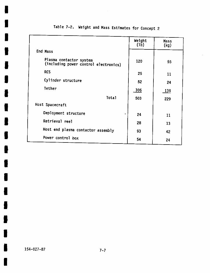
Table 7-2. Weight and Mass Estimates for Concept 2
End Mass
Plasma contactor system (including power contro
RCS
Cylinder structure
Tether
8 I B I I;
I i 1 U I 4 1 I B I I B
1 I 154-027-87
electronics)
Total Host Spacecraft
Deployment structure
Retrieval reel
Host end plasma contactor assembly
Power control box
7-7
120
25
52
306
503
-
24
28
93
54
Mass (kg)
55
11
24
139
229
-
11
13
42
24

7.4 DEPLOYMENT SCENARIO AND END MASS
The remainder of t h i s section addresses the deployment scenario and end mass fo r Concept 2. about 1 m/s i s imparted t o the end mass by spr ing actuators. will be suff ic ient t o propel the end mass t o a position where the gravity gradient force will sustain the play out. Cold gas thrusters will provide a backup force source.
To begin the deployment, an i n i t i a l velocity of T h i s velocity
The end mass i s mated t o a matching deployment cylinder containing separation springs and pulleys that route the tether t o an external retrieval reel . releasable clamp forming a strong and simple structure well suited t o resist launch loads and permi t t ing a symmetrical application of load from the separation springs.
The end mass i s secured t o the deployment cylinder by a
The s t a t i c reel is an annular cavity i n the end mass cylinder containing the coiled tether. A sheet metal closure a t one end res t ra ins the coil dur ing ground handling and launch of the host vehicle. The closure is formed w i t h a l i p concentric t o a central hub t o create a c i rcu lar s l o t from which the te ther plays out during deployment. A one shot energy absorber is incorporated i n the l a s t few co i l s t o reduce the end mass velocity and associated deceleration loads. The fu l ly deployed tether will a lso ac t as a low ra te spr ing t o l imit the deceleration force.
The power control electronics described i n the previous section are housed w i t h i n the end mass cylinder and the solar array i s attached t o the exter ior surface.
The deployment cylinder is mounted on a pa l le t together w i t h the host vehicle plasma contactor assembly, a power control electronics module and an optional te ther retrieval reel . The retrieval reel would be used t o return the end mass t o the host vehicle a f t e r completion o f the experiment t h u s eliminating concerns o f space debris and permitting post f l i g h t evaluation of hardware should t h a t be desired.
154-027-87 7-8

8. INTEGRATION WITH OMV AND EURECA
Preliminary analysis of the integration o f the PMG t e ther system w i t h the two candidate host spacecraft has been completed. Since EURECA is designed t o be an all-purpose payload host, i t appears t h a t the only s ignif icant modiflcation required is the use o f the expanded so lar array option. OMV would require the addi t ion of a truss structure and complete power k i t t o accommodate the payload. Table 8-1 presents weight and mass estimates f o r the additional hardware fo r OMV. The array is sized fo r 3 kW o f power.
Table 8-1. Weight and Mass Estimates of Additional Experiment Hardware fo r OMV
Solar arrays
Truss s t ructure
Tie downs, release mechanisms and contingency
I
396 I 180
176
57 - 629
80
26
286
Both vehicles easily accept the PMG hardware components and, f o r OMV, the orbiter does not constrain the length of the deployer/end mass cylinder. W i t h EURECA, the cylinder axis i s normal t o the o rb i t e r x axis and is therefore constrained by the 180 inch diameter payload envelope. This does not appear t o present a serious design problem, but must be addressed when selecting a deployment approach.
Figure 8-1 and 8-2 depict the PMG te ther system on the OMV and on EURECA.
154-027-87 8- 1

ORBIT DIRECTION
HOST VEHICLE PLASMA CONTACTOR
POWER CONTROL ELECTRONICS END MASS ASSEMBLY
SOLAR ARRAY
RELEASE CLAMP
TETHER RETRIEVAL
& SOLAR ARRAY ROTATION
Figure 8-1. PMG Tether System on OMV
8-2

I c
8-3
s w K C ' u K
-
4 w
E 0
E L)
L W c c, W I-
. N I 00 W L =I 0,
L -

I I b I D B 1 1 I B n I n I 1 I u
1 m 154-027-87
bel ow:
1.
2.
3.
4.
5.
6.
9. COST ESTIMATES
As part of the production of performance figures, cost estimates of the hardware and project level elements defined during the study were prepared. Since the definition of the PMG tether system/host spacecraft interface remains incomplete, along with mission operations support, launch system/host spacecraft services and PMG tether system/launch system interface, it is very likely that the cost of the actual system will be higher.
Additional ground rules and assumptions for these estimates are 1 i sted
Estimates are provided for deployer in end mass configuration (Concept 2).
Cost stated in millions of 1987 dollars.
Cost given through cost of money and do not include fee or profit . Cost for each item includes: project management; system engineering; design, development and hardware manufacturing; system integration assembly, test and verification; and management reserve.
With the exception of the OMV accommodations, 100% new design on each line item is assumed.
OMV accommodations cost is estimated as a procured item without design or development cost.
With the exception o f the tether for which an estimate was obtained from the vendor and of launch operations support for which a level o f effort was assumed, all other tether system items were estimated using the RCA PRICE H model. The OMV accommodations were estimated by analogy to TRW spacecraft. A low and a high estimate is given by line item in Table 9-1. These reflect the range of manufacturing complexity for each item.
9- 1

Table 9-1. Cost Estimates for Elements of
Item
Host Vehicle Hardware
Deployment assembly Plasma contactor assembly Power control assembly Pal let assembly
Tether
End Mass Hardware
Deployment/structure assembly Plasma contactor assembly Power control assembly Electrical power assembly Reaction control system assembly
Launch Operations Support
Total
OMV Accommodations
Host Vehicle Retrieval Assembly
154-027-87 9-2
the PMG Tether System
Cost ($M FY87)
0.4 to 0.5 0.5 to 0.6 5.5 to 6.3 1.3 to 1.6
0.2 to 0.3
0.8 to 1.0 0.5 to 0.6 1.2 to 1.4 1.0 to 1.1 6.1 to 7.0
0.0 to 1.0
17.5 t o 20.5
2.5 to 3.5
0.3 to 0.4

I I 1 I I I I I 1 I I I IC I 1 I i I 154-027-87
10. ENVIRONMENTAL CONCERNS
A study was performed t o determine the impact o f the meteoroid and debr is environment on the performance o f the PMG t e t h e r system. Two concerns were considered: the number of impacts s u f f i c i e n t t o sever the t e t h e r pe r year and power losses due t o penetrat ion o f the t e t h e r i n s u l a t i o n r e s u l t i n g i n exposure o f the high voltage t o the ambient plasma.
For the t e t h e r i n Figure 5-1 the t o t a l surface area i s 91.1 m2. An o r b i t a l a l t i t u d e o f 400 km was assumed. This a l t i t u d e i s one o f the few f o r which a debr is environment spec i f i ca t i on has been defined. The environmental d e f i n i t i o n s are from the NASA model f o r meteoroids (Reference 11) and a modif ied version of the Space S ta t i on debr is model (Reference 12). increase the number o f p a r t i c l e s by a factor o f 11 (Reference 13). The debr is environment i s a l t i t u d e dependent whi le the meteoroid environment i s considered t o be constant.
The modi f icat ion imposed on the debr is model was t o
I t was determined t h a t a p a r t i c l e w i t h mass greater than o r equal t o 10-4 gm could penetrate the t e t h e r a l l the way through. Based on the area o f the t e t h e r and the d i s t r i b u t i o n o f pa r t i c l es , i t was determined t h a t the number o f impacts capable of severing the t e t h e r i s 0.3 per year f o r meteoroids and 0.5 per year f o r debris.
During the per iod o f 1 year, the number o f penetrat ions i n the i n s u l a t i o n would be about 10 from meteoroids and up t o 275 from debr is p a r t i c l e s . Assuming a uniform d i s t r i b u t i o n o f the 285 holes, the power l oss f o r the 2 kW system would be about 12 W o r less than 1%. There could be arc ing i n the regions o f the t e t h e r t h a t operate above about 800 V.
10-1

I I I I I I I I I 1 I I I I u B
I I 154-027-87
11. DEPLOYMENT SIMULATIONS
In this section, the results of deployment simulations performed a t the Energy Science Laboratories, Inc. using their computer simulator, BEADSIM, are presented. The issues investigated were the location of the deployer, deployment scenarios, s ta r t ing methods and deceleration a t the end of the deployment. The recommendations proposed i n this section were incorporated i n the design of the end mass and deployer fo r Concept 2 i n Section 7.
11.1 DEPLOYMENT ISSUES
In addition t o the reasons already given, locating the deployer i n the end mass r e su l t s i n several other desirable features. i ne r t i a l e f fec ts , the te ther tension during deployment is less on the deployer end than on the other end. If the deployer is i n the end mass, the force required t o decelerate can be f a r less. Also, the kinetic energy t o be absorbed a t the end of deployment i s only due t o the end mass emptied of the tether, since the te ther is not moving away from the host vehicle. Finally, the tension dur ing deployment can be measured more easi ly a t the fixed end t h a n a t the deployment end. Since the fixed end i s the spacecraft , monitoring is faci 1 i tated.
For one, due t o
The only disadvantage t o putting the deployer i n the end mass is that low tip-off ra tes become more important t o prevent the tether from wrapping around the end mass as i t unreels. Tip-off ra te refers t o the rotation o f the end mass i n iner t ia l space. No problem is expected fo r t ip-off rates l e s s than a few degrees per second.
A high impulse deployment method started by springs is recommended t o ensure a smooth unreeling. Spacecraft thrusters under ground control can be used i f a jam occurs. Further tes t ing is needed t o determine the tension during deployment. To decelerate a t the end of the deployment a one-shot energy absorber, perhaps bonding the l a s t t u r n on the core, is recommended.
11-1

11.2 BEADSIM SIMULATIONS
BEADSIM was developed t o simulate the Small Expendable Deployment I t does not model tension
I t can incorporate System (SEDS) currently under study for NASA. variations along the te ther which can be large. detailed data on the wire properties. The parameters s tudied include the deployment tension, deployment direction, packing fraction which is the r a t i o of the area o f the core t o the outer diameter of the stored t e the r and the f inal braking tenslon.
The resu l t s of these studies are t h a t a 45 degree angle of deployment i s best bu t any angle between 0 and 90 degrees i s acceptable. An i n i t i a l velocity of 1 m/s is recommended fo r the deployer located on the end mass. The range ra tes a t the end of deployment will be 2 t o 8 m/s depending on the deployer. Typical deployment time fo r a 10 km te ther i s less than 1 orbi t .
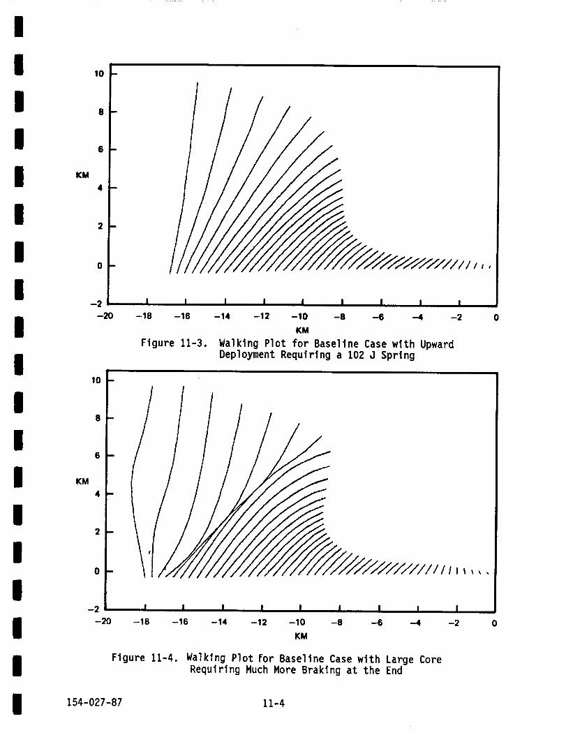
Graphic output from four representative BEADSIM simulation runs fo r the PMG t e ther deployment consti tute Figures 11-1 through 11-4. These "multiple exposure pictures" o r "walking plots" show the te ther shape and posi t ion i n a rotating local vertical local horizontal reference frame a t 2-minute intervals during deployment. Each curve is displaced 0.4 km t o the l e f t , the direction of orbital motion. The four cases displayed are:
1. Baseline Case: deployer on end mass, 45 degree angle of deployment, small core, 65 J spring
2. Baseline case bu t w i t h large core
3 .
4.
Baseline case b u t w i t h upward deployment requiring a 102 J sp r ing
Baseline case b u t w i t h OMV-mounted deployer requlring a 260 J sp r ing and more braking.
154-027-87 11-2

10
8
6
KM 4
2
0
-2 I t I I I I I I I
-14 -12 -10 -8 -6 -4 -2 0 -20 -18 -16
10
8
6
KM 4
2
0
-2
KM Figure 11-1. Walking Plot for Baseline Case: Deployer on End
Mass, Deployment Up and Forward (45 Degrees) , 65 3 Spring and Small Core
-8 -6 -4 -2 0 -20 -18 -16 -14 -12 -10
KM Figure 11-2. Walking Plot for Baseline Case with 260 J
Spring and Deployer on OMV
11-3
10
8
6
KM 4
2
0
-2 -20 -18 -16 -14 -12 -10 -8 -6 4 -2 0
KM Figure 11-3. Walking Plot for Baseline Case with Upward
Deployment Requiring a 102 J Spring
10
8
6
KM 4
2
0
-2 -20 -18 -16 -14 -12 -10 -8 -6 -4 -2 0
KM
Figure 11-4. Walking Plot For Baseline Case with Large Core Requiring Much More Braking a t the End
154-027-87 11-4

I I I l I I I 1 I I I I I I I I I
I I 154-027-87
12. ENGINEERING DEVELOPMENT PROGRAM
The engineering development program consists of a two-part plan, one fo r technology development and one fo r systems requirements and conceptual design. The PMG t e the r system design influences the scope of the technol ogy development . Conversely, the progress of tether technol ogy influences the actual requirements and conceptual design. The goal is t o maximize the use of off-the-shelf subsystems and hardware t o ensure low cost and reduced technical risk.
A schedule and tasks fo r the engineering development program are shown i n Figure 12-1. The f i r s t phase provides time fo r a thorough engineering understanding of the te ther system design and i ts interactions w i t h OMV and EURECA. The result will be a deeper knowledge of a l l spacecraft and PMG interfaces. T h i s will also permit a fu l l validation of system requirements and of the operations concepts.
The preliminary design and c r i t i ca l design phases a re conventional disciplines. These phases will yield a design tha t meets requirements and is producible. Subsystems development and test of the six elements o f the PMG t e the r system proceed i n paral le l . Assembly of the PMG te ther system from the subsystem elements i s accomplished and the system i s integrated t o the host spacecraft/platform, (e.g., OMV). Prelaunch, launch, and on-orbit operations a re short-term, intensely active and cr i t ical ac t iv i t i e s . They culmlnate the en t i r e e f fo r t by demonstrating the PMG te ther system in a motor mode f o r orb i t reboost.
12-1

I I ~I ~I I I I I I I I I I I I I I I I
UNDERSTANDING PHASE
PRELIMINARY DESIGN PHPSE
CRITICAL DESIGN PHASE
SU~YSTEMS DEVELOPMENT AND TEST
&SSEMBLY.TEV,AND VERIFICATION
PRELAUNCH AND LAUNCH1 ONORBIT ASSEMBLY SUPPOR1
SIX MONTH INITIAL FLIGHT WERATIONS SUPPORT
TIME (MONTHS1
I I DEPLOYER
1 TETHER
1 - - I
I PMADS
P W M A CONTACTOR
XENON VORAGE AND MANAGEMENT
SPACECRAFT INTERFACE KIT
Figure 12-1. Engineering Development Schedule
12-2

I 13. CONCLUSIONS AND FUTURE WORK
T h i s study has produced detailed designs fo r a 2 kW PMG Tether System based largely on exi s t ing hardware and hardware designs . Speci f i cal ly , the hollow cathode design and electronics are derived from ion propulsion equipment. A prototype te ther has been constructed and, during planned future study, will undergo deployment t e s t s and tests fo r strength, resistance t o breakage and abrasion and electr ical properties. In addition, laboratory development models of the electronics will be used t o operate two PMG hollow cathode assemblies w i t h this t e the r t o verify e lec t r ica l performance parameters fo r the complete system.
Based on the dynamical properties gathered during the t e s t o f the prototype te ther , refined simulations of the deployment using BEADSIM and of long term s t a b i l i t y character is t ics using the current version o f GTOSS will be performed.
The mission selection process yielded f ive spacecraft or missions t o host the f l i gh t demonstration of the PMG tether system. Of these, OMV and EURECA a re the most promising. More detailed e lec t r ica l and mechanical integration studies will be performed as part o f the follow-on ac t iv i t ies . Based on the resu l t s of these studies, an update cost estimate will be generated.
The resu l t s presented i n this report show t h a t a low cost demonstration of a PMG Tether System appears t o be feasible by the middle of the 1990s. The potential for this innovative technology as a supplement t o both propulsion and electr ical subsystems fo r some future spacecraft and missions clear ly j u s t i f y such a demonstration.
154-027-87 13-1

14. REFERENCES
I ' I I
I I
1. James E. McCoy, "Electrodynamic Tethers I. Power Generation i n LEO 11. Thrust f o r Propulsion and Power Storage," I A F Conference paper, 1984.
2. James E. McCoy, "P1 asma Motor/Generator Reference System Designs f o r Power and Propulsion, " NASA/AIAA/PSN In te rna t i ona l Conference on Tethers i n Space, 1986.
3. P.J. Wilbur and J.D. Will iams, "An Experimental I nves t i ga t i on o f the Plasma Contacting Process," A I A A Paper 87-0571, January 1987.
4. M.J. Patterson and P.J. Wilbur, "Plasma Contactors f o r Electrodynamic Tether," NASA TM-88850, September 1986.
5. J.R. Beatt ie, J.N. Matossian, R.L. Poeschel and R. M a r t i n e l l i , "Xenon Ion Propulsion Subsystem," A I A A paper 85-2012, September 1985.
6. J. Hermel, R.A. Meese, W.P. Rogers, R.O. Kushida, J.R. Bea t t i e and J. Hyman, "A Modular, Ion Propulsion, O r b i t Transfer Vehicle," A I A A paper 86- 1394, June 1986.
7. H.R. Kaufman, R.S. Robinson and D.C. Trock, " I n e r t Gas Thruster
8. W.D. Deininaer, G. Aston and L.C. Pless. "Hollow Cathode Plasma Source
Technology," J. Spacecraft and Rockets 20, pp. 77-83, 1983.
f o r Act ive Spacecraft Charge Control," Rev. Sci. Instrum. 58, pp. 1053- 1062, 1987.
9. H.B. Garret t and G.C. Spi ta le, "Magneospheric Plasma Modeling 0-100 kV)," J. Spacecraft and Rockets 22, pp. 231-244, 1985.
10. A. Konradl, B. McIntyre and A.E. Potter, "Experimental Studies o f Scal ing Laws f o r Plasma Co l l ec t i on a t High Voltages," J. Spacecraft and Rockets 21, pp. 287-292, 1984.
11. B.G. Cour-Palais, "Meteoroid Environment Model - 1969: Near Earth t o Lunar Surface," NASA SP-8013, 1969.
12. D.J. Kessler, "Orb i ta l Debris Environment f o r Space Station," JSC- 20001.
13. L.G. Taf f , " S a t e l l i t e Debris: Recent Measurements, " 3. Spacecraft and Rockets 23, pp. 342-346, 1986.
154-027-87 14-1
~~ -~ ~


![Tether anthony[1]](https://img.pdfslide.us/doc/110x75/557c7d36d8b42a494c8b5161/tether-anthony1.jpg)