Embed Size (px)
Citation preview
MSIWF research grant Page1
Study of effects of vehicle‐front shapes and impact speeds on post –crash kinematics and injury mechanisms
Julaluk Carmai Sujeeprapa Charoenthong and Wachirut Kongsakul Faculty of Engineering, King Mongkut’s University of Technology North Bangkok
Summary
Pedestrian collision is one of the frequent causes of fatalities worldwide. In order to increase safety for pedestrians, it is necessary to understand pedestrian‐vehicle collisions and injury mechanisms. The aim of the research is to investigate the pedestrian collisions and injuries caused by impact of different vehicle front profiles at various speeds by means of finite element pedestrian‐vehicle crash simulations. Ten simulations of pedestrian‐vehicle collisions for the bonnet‐front city car and the flat‐front passenger bus with impact speeds of 20km/h 30km/h and 40 km/h at impact angles
of 90 and 45 have been conducted. It has been found that impact speed has had significant influences on pedestrian injury severity. The greater the impact speed the higher risk of injury. The results have also indicated that the front‐profile of vehicle has a large effect on the overall post‐crash kinematics of the pedestrian and injury characteristics due to the different in contact time, impact location and impact velocity of each body region of the pedestrian. The bonnet‐front city car has caused high acceleration of the head while the flat‐front bus has caused high acceleration to the chest. Impact angle is also a factor that affects the post crash‐kinematics and impact location of the body part. Different types of vehicle require different design to reduce pedestrian fatalities as the post‐crash kinematics is different.
1. Introduction Vehicle‐to‐pedestrian collisions often cause serious injuries and deaths dramatically as pedestrians do not have any protection equipment
unlike occupants in cars. The reduction of pedestrian injuries has recently become one of the most important road traffic accident priorities. Most of car manufacturers have currently focused on designing cars for occupant safety and given less priority to pedestrian safety. In order to increase safety for pedestrians, it is necessary to understand post‐crash kinematics and injury mechanisms of vehicle‐to‐pedestrian collisions. There are many factors that have influences on post‐crash kinematics such as impact speeds, posture of pedestrians, impact angle, height of vehicle and profile of vehicle front structure. Interaction study between pedestrian and vehicles in various crash situations will provide important information to improve the vehicle design and make vehicle safer to people walking down the street. Vehicle‐to‐pedestrian collisions study can be done through full‐scale crash tests of a dummy or a cadaver. However, the full‐scale crash tests are very expensive. Computer simulation, in particularly, finite element simulation, has gained much attention this day as an alternative method to the costly actual crash test.
This paper has addressed the development of vehicle‐to‐pedestrian collision finite element model. This model has been used to study influences of front‐shape of vehicles impact speed and impact angles on post‐crash kinematics and injury mechanisms of a pedestrian. A series of parametric studies has been carried out using a human pedestrian finite element model, a city‐car and a passenger bus finite element models. With these two different vehicle‐front profiles, two impact angles, 90˚ and 45˚have been studied at 20km/h 30km/h and 40km/h vehicle impact speeds. Pedestrian post‐crash kinematics and injury mechanisms have been investigated and the injury risk has been analysed and discussed in terms of the injury parameters. The report has started with the development of FE model and their validations. Then ten simulations have been carried out. The results and discussion have been presented. Finally the findings and conclusion have been given.
2. Development of vehicle‐to‐pedestrian finite element model
2.1 Vehicle finite element models
Two types of vehicle with different front‐profile structure have been studied, a city sedan car and a passenger bus. A compacted size city car, which is mostly used in the city, has high possibility to collide with pedestrians. As well as a passenger bus which commutes only in the city center. The finite element models of these two vehicles are described below.
The City Car model The 2010 Toyota Yaris sedan, which has similar structure to the 2010 Toyota Vios model in Thailand was selected. Its finite element model
was based on the NCAC (National Crash Analysis Center). The model was originally created for frontal crash simulations. The NCAP frontal
crash simulation was run with 56 km/hr speed to reconfirm its accuracy with the NCAP actual test results [1] . The comparisons between the
simulation results and the NCAP crash test data are shown in figure 1 and 2. The global responses of the crashed car are comparable.
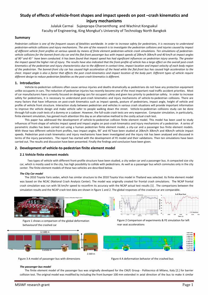
The passenger bus model The finite element model of the passenger bus was originally developed for the CM/E Group ‐ Politecnico di Milano, Italy [2.] for barrier
collision test. The original model was modified by including the front bumper 100 mm extended in axial direction of the bus to make it similar
Figure 1 shows a comparison of the global deformation
behaviourof the crashed car
Figure 2 Comparison of experiments & FE simulation for left
rear seat accelerations
Figure 4 A deformation behavior of the crashed bus
12.688 m
0.6506 m
2.793 m
2.569 m
Figure 3 A model of passenger bus with dimensions

MSIWF research grant Page2
to the passenger bus in Bangkok. The dimensions of the bus are shown in figure 3. Details of the bus passenger parameters and material
used are given in [2]. The full frontal crash simulation of the passenger bus model with a fixed flat barrier was conducted for 800 ms with an
impact speed of 8km/h. Since the current bus model used in this paper has no actual test data available for validation, the actual frontal crash
test data available in the literature were taken for a purpose of initial validation. The physical crash test data of the US low floor mass transit
bus [3] was used instead. The CM/E group bus is longer and 22% heavier but the width and height are close. Comparisons of simulation results
and actual test results are shown in figure 5. The trend of bus CG velocity and displacement were similar. The value of CG velocity was the
same but the velocity taken from the actual test dropped faster because the difference in mass. The validation was reasonably fine.
Figure 5 Comparison of the bus CG displacement and velocity between simulation and test
2.2 A pedestrian human model The Total Human Body for Safety (THUMS) model was employed for a pedestrian of height 175 cm and weight 77 kg. THUMS version 4 used in
this study included the skeleton, muscle, internal organ and brain. The model reflects real responses of human body unlike the dummy model which cannot give detail of injury characteristics. Figure 6 show the THUMS and its organs. Each body region has already been validated [4].
2.3 Vehicle‐to‐pedestrian crash simulations preparation Ten simulations as summarized in table 1 were carried out for 4 arrangements of vehicle‐to‐pedestrian collisions. THUMS was positioned in
front of the vehicle at its centerline making 90˚ and 45˚ to the width of the vehicles. The vehicle was set to impact the pedestrian on the right side as shown in figure 7. Each arrangement was simulated with vehicle impact speeds of 20km/h and 30km/h only for 45˚ impact angle was also simulated with 40km/h. Both the vehicle and the pedestrian model were placed in the acceleration field of gravity and the pedestrian was hit by the vehicle immediately after the start of the FE analysis calculations.
Table 1 Simulation matrix
3. Results and discussions 3.1 Overall kinematics behaviour 3.1.1 The city car‐to‐pedestrian collision
Figure 8 shows the kinematics behaviour of an adult pedestrian struck by the city car at impact angles of 90˚ and 45 as well as at three different impact speeds. The kinematics of the pedestrian with impact angle of 90˚ but at 20 km/h (case I) and 30 km/h (case II) were similar. The knee was firstly struck by the bumper followed by the thigh and tibia almost at the same time. The front bumper deformed and the lower extremities bent along the car’s frontal contour. The upper body rotated around the vehicle front area leading to the pelvis collision with the bonnet leading edge. The right side of the chest was impacted by the hood top. Since the neck behaved like a joint which allowed rotation degree of freedom, the head was angularly accelerated and made contact with the lower windshield frame. Finally the whole body bounced off the car. The head resultant velocities and accelerations were shown in figure 9 and 10. It was found that during impact the head velocities were higher than the vehicle impact speeds. This was because the head picked up additional angular velocity from the rotation about the front of the car. The kinematics behavior of pedestrian struck at impact angle of 45˚ was a bit different. The initial contact was at the right lower extremity. The right leg was bent while the left leg was still straight. The back of the pelvis (bottom) was struck by the bonnet leading edge. The back of the chest and head were impacted the bonnet and the windshield respectively. The pedestrian lied on the bonnet with its back before bouncing off the car. The overall kinematics was almost the same for the collisions at the same impact angle. However, the dynamics responses of the injury parameters were different as shown in figure 9 and 10. The graph of head and chest acceleration were high when the car impact speeds were high. The knee bending and the contact time for each case were different. However, the chest acceleration was not much different when comparing at the same angle. At the same impact speed, the head accelerations were almost the same but the contact time was slightly different. In contrast, the chest acceleration of the one with 45˚ was much higher.
3.1.2 The passenger bus‐to‐pedestrian collision Figure 12 shows kinematics behavior of the pedestrian being struck by a passenger bus at 90˚ and 45˚ with different impact speeds.
Vehicle City car Passenger bus
Impact angle 90˚ 45˚ 90˚ 45˚
Impact velocity 20 km/h 30 km/h 20 km/h 30 km/h 40 km/h 20 km/h 30 km/h 20 km/h 30 km/h 40 km/h
Case number I II III IV V VI VII VIII VIII X
Figure 6 A THUMS pedestrian finite element human model Figure7 Simulation set‐up of vehicle‐to‐pedestrian collisions a) Car‐Pedestrian
with 90 impact angle b) Car‐Pedestrian with 45 impact angle c) Bus‐Pedestrian
with 90 impact angle d) BUS‐Pedestrian with 45 impact angle

MSIWF research grant Page3
The kinematics behaviour of pedestrian struck at impact angle of 90˚ and 45˚ was different. For 90˚impact angle, the knee was impacted with the bumper followed by the striking of pelvis and the upper body with the front panel immediately. No rotation of the torso was observed due to the flat‐front shape. Slight bending of the lower extremities was seen. The head was lastly impacted by the windshield. Different kinematics was observed for 45˚. After the first impact with the lower extremities and the chest with the flat front panel, the whole body was twisted leading to the impact of the back with the bus front surface. The global kinematics was almost similar at impact speeds of 20km/h 30km/h and 40km/h for the same impact angle. However, the dynamics responses which related to injury risk of fatalities were different as shown in figure 13‐15. It was found that the head and chest accelerations depended strongly on the vehicle impact speeds. Chest acceleration was as high as head acceleration. At the same impact speed, the head and chest accelerations obtained from different impact angles were not much different.
3.2 Effects of front profiles of vehicle on the kinematics behavior and injury parameters Pedestrian collides with the city car and the passenger bus caused significantly different post‐crash kinematics as shown in figure 8 and 12
hence different injury characteristics and mechanisms. All cases that involved the collisions with the city car, the dominated kinematics were the wrapping of the lower extremities about the bumper and the rotation of the upper torso and head. These led to high bending at the knee and high stress at the lower extremities as shown in figure 16. In addition the head impact accelerations were high as a result of its high vertical component of velocity. In collision of the passenger bus, the dominated kinematics was the upper body impact at short contact time and the forward projection of the pedestrian away from the bus. The chest was impact at high velocity because the whole body was struck by the flat‐front surface within a relatively short duration. Since there was little rotation of the head occurs, the head impact acceleration was lower compare to the collision with the city car. In contrast, the chest impact velocities ware low in the city car collision since the time duration was longer the chest velocity relative to the vehicle decreased. The kinematics behavior affects the body region’s impact velocities and the loading of each body region. Figure 16‐18 show comparisons of stress and strain on each region, including internal organs, of the pedestrians being struck by the city car and the
bus at 40km/h at 45 impact angle. The injury characteristics were different if colliding with different vehicle front‐profile. Moreover, the injury risk depended on impact locations impact velocities and the stiffness of the local structures.
4. Finding and Conclusions Ten finite element simulations were conducted to study three pre‐crash factors. It was found that impact speed was the critical factor that influenced
the post‐crash kinematics and the level of injury. The higher the impact speed the higher risk of fatal injuries. In addition, the impact angle also influenced the post‐crash kinematics and fatal injury risk. The post‐crash kinematics obtained from 45˚ impact angle and 90˚ impact angle were different. Moreover, the front profile of the vehicles in the current study exhibited significantly different post‐crash kinematics hence different injury characteristics and mechanisms. Risk of severe injury occurred at the lower extremities and head for the city car‐pedestrian collision. While for the bus‐pedestrian collision, it occurred at chest, pelvic and head. The pedestrian being hit by the bus were detached and projected forward from the bus which lead to high risk of severe second and third impacts. While, the pedestrian lied on the bonnet or was slightly bounced away from the bonnet for the city car collision.
Figure 9 Head resultant velocity for the city car
collisions
Figure 11Chest resultant acceleration for the city car collisions
Figure 8 Overall kinematics behavior of pedestrian struck by the city car at different impact angles and speeds
Figure 10 Head resultant acceleration for the city car
collisions

MSIWF research grant Page4
5. References [1] NCAC, “development and validation of a finite element model for a 2010 Toyota Yaris sedan” NCAC 2011‐t‐001, prepared for FHWA, dec 2011 [2] Finite Element Model Archive, FHWA/NHTSA National Crash Analysis Center, Available online :http://www/ncac.gwu.edu/vml/models..html [11.3.2008] [3] Sachin Shivaji Kumbhar. “Development of a finite element model and analysis of a rear impact scenario of a low‐floor mass transit bus,” 2006 [4] Total Human Model for Safety documentation: AM50 Pedestrian/Occupant model Academics V4.0_2011003, October 2011. Toyota Motor Corporation
6. Future areas to take note of, and Going forward The research results can be utilised as input information for the design or modification of the vehicle front profile to make it more pedestrian
friendly. In addition, the human pedestrian finite element model employed in this research can also be used to further study the pedestrian injury risks and injury mechanisms of other types of vehicle such as commuter van and motorcycles which have been used widely in Thailand.
7. Means of Official announcement of research results A part of the research has been submitted to the International Conference on Automotive Engineering 10 which will be held on 1‐3 April 2014. In addition, complete results will be submitted for publication in an international journal.
Figure 14 Head resultant accelerations
for the bus collisions
Figure 15 Chest resultant accelerations for the bus collisions
a)
b)
Figure 17 Strain distributions on head and brain a)
in the collision with the city car b) in the collision
with the bus
90 impact 45 impact
Figure 18 Stress and strain distributions on rib
and organs a) in the collision with the city car
b) in the collision with the bus
b)
a)
b)
a)
Right Lung
Liver
Right Lung
Figure 12 Overall kinematics behavior of pedestrian struck by the bus at different
impact angles and speeds
Figure 16 Stress distributions on lower
extremities a) in the collision with the
city car b) in the collision with the bus
Figure 13 Head resultant velocities
accelerations for the bus collisions