Embed Size (px)
Citation preview

materials
Article
Study of Different Sol-Gel Coatings to Enhance theLifetime of PDMS Devices: Evaluation ofTheir Biocompatibility
María Aymerich 1, Ana I. Gómez-Varela 1, Ezequiel Álvarez 2 and María T. Flores-Arias 1,*1 Photonics4 Life Research Group, Departamento de Física Aplicada, Facultad de Física,
Universidade de Santiago de Compostela, Santiago de Compostela 15782, Spain;[email protected] (M.A.); [email protected] (A.I.G.-V.)
2 Instituto de Investigación Sanitaria de Santiago de Compostela (IDIS), Complexo Hospitalario Universitariode Santiago de Compostela (CHUS) SERGAS, Santiago de Compostela 15706, Spain;[email protected]
* Correspondence: [email protected]; Tel.: +34-88-181-3502
Academic Editor: Fu Hsiang KoReceived: 20 July 2016; Accepted: 23 August 2016; Published: 25 August 2016
Abstract: A study of PDMS (polydimethylsiloxane) sol-gel–coated channels fabricated using softlithography and a laser direct writing technique is presented. PDMS is a biocompatible material thatpresents a high versatility to reproduce several structures. It is widely employed in the fabricationof preclinical devices due to its advantages but it presents a rapid chemical deterioration to organicsolvents. The use of sol-gel layers to cover the PDMS overcomes this problem since it provides therobustness of glass for the structures made with PDMS, decreasing its deterioration and changing thebiocompatibility of the surface. In this work, PDMS channels are coated with three different kinds ofsol-gel compositions (60MTES/40TEOS, 70MTES/30TISP and 80MTES/20TISP). The endothelial celladhesion to the different coated devices is evaluated in order to determine the most suitable sol-gelpreparation conditions to enhance cellular adhesion.
Keywords: sol-gel; laser writing technique; soft lithography; PDMS devices; cell adhesion
1. Introduction
The fabrication of preclinical devices, such as microfluidic or lab-on-a-chip systems, has hada huge impact and has received great interest due to the wide variety of medical and biologicalapplications that these devices present. From diagnosis [1] to the study of flow conditions withdifferent cardiovascular systems [2], these kinds of devices have a huge potential to carry out thesimulation of pathologies in a small area and under controlled conditions [3]. These artifacts can mimicbiological structures such as small capillaries [4], larger vessels [5,6], a simple channel or a complexminiaturized laboratory [7,8].
For these systems, a wide range of materials are employed, including glass [9], silicon [10] orthermoplastic polymers [11], among others. One of the most suitable materials for the fabricationof the chip devices is polydimethylsiloxane (PDMS) [12] due to its capability to replicate structureswith accuracy down to the nanometer scale. It is a cheap material with a good permeability for gaseswhich allows cells to receive oxygen when they are cultured on PDMS chips. Its optical transparencyallows the necessary microscopy inspections. Its composition does not present any toxicity and itis biocompatible.
Different techniques have been reported for fabricating these kinds of devices, for instancephotolithography [13] or laser micromachining [14]. When using PDMS, the most common andimplemented replication technique is soft lithography [15,16], which allows us to obtain an accurate
Materials 2016, 9, 728; doi:10.3390/ma9090728 www.mdpi.com/journal/materials

Materials 2016, 9, 728 2 of 11
replica of a determined master in an easy and fast way. Masters can also be obtained by othermethods, such as cutting plotter [17] or lithography [18]. Among all the possible techniques, laserstructuring stands out due to its accuracy, speed, versatility and non-contact nature [19]. Laser ablationis commonly carried out with nanosecond pulsed lasers, which are the more implemented in theindustry than those that operate in the femtosecond regime. Some of the authors have studied thelaser direct writing technique over glass, which presents itself as a very suitable material for masterfabrication mainly due to its hardness and resistance [20].
As we mentioned before, microfluidic and preclinical devices are commonly fabricated with PDMSdue to its advantages but it also presents one important disadvantage: the degradation of the materialwhen organic solvents are used. These substances, which are commonly employed in biomedicalassays, degrade and deteriorate the PDMS, making the device non-reusable. A solution to overcomethis problem is to coat the PDMS chips via the sol-gel chemical route. This procedure provides thestructure with the chemical robustness of the glass and preserves the biocompatibility and transparencyproperties without significantly altering the geometry of the PDMS device [21,22]. Sol-gel chemistryoffers some unique opportunities for the synthesis of optical materials over existing productionmethods including the control of the composition and the low processing temperature [23–25].The process gives excellent control of its purity and composition since it starts with pure materials.
The dip-coating technique is one of the easiest techniques to obtain coatings using a liquiddeposition with a huge variety of inorganic, hybrid and nanocomposite materials. It allows us todeposit layers and to coat different complex surfaces, for instance with holes or intricate shapes,enabling a flexibility that is not possible with other conventional techniques. By coating PDMS deviceswith sol-gel, the geometry of the devices can be preserved but the surface where cells are going to becultured is modified and, therefore, cellular behavior over the material will be different compared tothe behavior over non-coated PDMS. The composition of the cover layers can be chosen to enhance thecell adhesion.
In this work we present the fabrication of PDMS devices with channel geometry that can mimicblood vessels and may be employed in biomedical assays. The proposed chips are fabricated in aprocess of several steps, explained in detail in the Results section. The master is fabricated withlaser technologies and it is replicated by soft lithography methods. After that, the PDMS devices arecoated with different sol-gel compositions to overcome the deterioration problem. Human umbilicalvein endothelial cells (HUVEC) have been chosen to be cultured onto the different coated channels.The biocompatibility of each specific device is studied. A comparison among them is presented whenendothelial cells are seeded over the chips. Section 2 is devoted to the results obtained in the fabricationprocedure and the biological validation. Section 3 shows the discussion of the results and the mainconclusions of the work. Section 4 describes the materials and methods employed.
2. Results
In this section, a technique that combines laser and soft lithography to fabricate the master and thereplica of the channels, respectively, is presented. The channels are coated with different compositionsof sol-gel. The biocompatibility of each coating is evaluated in order to find the most suitable sol-gelcoating that reduces the deterioration of the PDMS [26,27] as well as to present the best environmentfor endothelial cells to attach and spread. These are key factors to perform successful bioassays withPDMS devices coated with sol-gel.
2.1. Fabrication of the Channel
Two steps compose the fabrication procedure of the final channels: first, a master of the channel isfabricated over a soda-lime glass with a pulsed nanosecond laser; second, a laser thermal treatment isapplied to reduce the roughness of the channels. Once the master is fabricated, the replica procedure iscarried out by soft lithography methods using PDMS material because of its biocompatibility.
Materials 2016, 9, 728 3 of 11
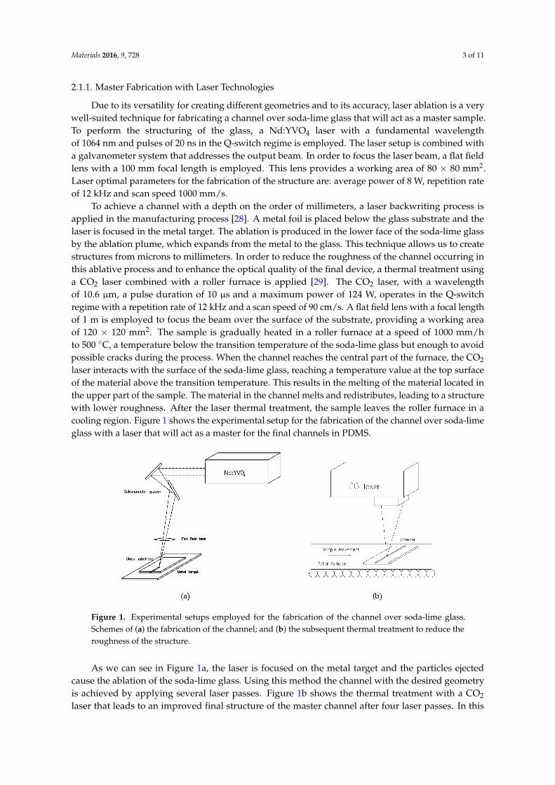
2.1.1. Master Fabrication with Laser Technologies
Due to its versatility for creating different geometries and to its accuracy, laser ablation is a verywell-suited technique for fabricating a channel over soda-lime glass that will act as a master sample.To perform the structuring of the glass, a Nd:YVO4 laser with a fundamental wavelengthof 1064 nm and pulses of 20 ns in the Q-switch regime is employed. The laser setup is combined witha galvanometer system that addresses the output beam. In order to focus the laser beam, a flat fieldlens with a 100 mm focal length is employed. This lens provides a working area of 80 × 80 mm2.Laser optimal parameters for the fabrication of the structure are: average power of 8 W, repetition rateof 12 kHz and scan speed 1000 mm/s.
To achieve a channel with a depth on the order of millimeters, a laser backwriting process isapplied in the manufacturing process [28]. A metal foil is placed below the glass substrate and thelaser is focused in the metal target. The ablation is produced in the lower face of the soda-lime glassby the ablation plume, which expands from the metal to the glass. This technique allows us to createstructures from microns to millimeters. In order to reduce the roughness of the channel occurring inthis ablative process and to enhance the optical quality of the final device, a thermal treatment usinga CO2 laser combined with a roller furnace is applied [29]. The CO2 laser, with a wavelengthof 10.6 µm, a pulse duration of 10 µs and a maximum power of 124 W, operates in the Q-switchregime with a repetition rate of 12 kHz and a scan speed of 90 cm/s. A flat field lens with a focal lengthof 1 m is employed to focus the beam over the surface of the substrate, providing a working areaof 120 × 120 mm2. The sample is gradually heated in a roller furnace at a speed of 1000 mm/hto 500 ◦C, a temperature below the transition temperature of the soda-lime glass but enough to avoidpossible cracks during the process. When the channel reaches the central part of the furnace, the CO2
laser interacts with the surface of the soda-lime glass, reaching a temperature value at the top surfaceof the material above the transition temperature. This results in the melting of the material located inthe upper part of the sample. The material in the channel melts and redistributes, leading to a structurewith lower roughness. After the laser thermal treatment, the sample leaves the roller furnace in acooling region. Figure 1 shows the experimental setup for the fabrication of the channel over soda-limeglass with a laser that will act as a master for the final channels in PDMS.
Materials 2016, 9, 728 3 of 11
2.1.1. Master Fabrication with Laser Technologies
Due to its versatility for creating different geometries and to its accuracy, laser ablation is a very well-suited technique for fabricating a channel over soda-lime glass that will act as a master sample. To perform the structuring of the glass, a Nd:YVO4 laser with a fundamental wavelength of 1064 nm and pulses of 20 ns in the Q-switch regime is employed. The laser setup is combined with a galvanometer system that addresses the output beam. In order to focus the laser beam, a flat field lens with a 100 mm focal length is employed. This lens provides a working area of 80 × 80 mm2. Laser optimal parameters for the fabrication of the structure are: average power of 8 W, repetition rate of 12 kHz and scan speed 1000 mm/s.
To achieve a channel with a depth on the order of millimeters, a laser backwriting process is applied in the manufacturing process [28]. A metal foil is placed below the glass substrate and the laser is focused in the metal target. The ablation is produced in the lower face of the soda-lime glass by the ablation plume, which expands from the metal to the glass. This technique allows us to create structures from microns to millimeters. In order to reduce the roughness of the channel occurring in this ablative process and to enhance the optical quality of the final device, a thermal treatment using a CO2 laser combined with a roller furnace is applied [29]. The CO2 laser, with a wavelength of 10.6 μm, a pulse duration of 10 μs and a maximum power of 124 W, operates in the Q-switch regime with a repetition rate of 12 kHz and a scan speed of 90 cm/s. A flat field lens with a focal length of 1 m is employed to focus the beam over the surface of the substrate, providing a working area of 120 × 120 mm2. The sample is gradually heated in a roller furnace at a speed of 1000 mm/h to 500 °C, a temperature below the transition temperature of the soda-lime glass but enough to avoid possible cracks during the process. When the channel reaches the central part of the furnace, the CO2 laser interacts with the surface of the soda-lime glass, reaching a temperature value at the top surface of the material above the transition temperature. This results in the melting of the material located in the upper part of the sample. The material in the channel melts and redistributes, leading to a structure with lower roughness. After the laser thermal treatment, the sample leaves the roller furnace in a cooling region. Figure 1 shows the experimental setup for the fabrication of the channel over soda-lime glass with a laser that will act as a master for the final channels in PDMS.
Figure 1. Experimental setups employed for the fabrication of the channel over soda-lime glass. Schemes of (a) the fabrication of the channel; and (b) the subsequent thermal treatment to reduce the roughness of the structure.
As we can see in Figure 1a, the laser is focused on the metal target and the particles ejected cause the ablation of the soda-lime glass. Using this method the channel with the desired geometry is achieved by applying several laser passes. Figure 1b shows the thermal treatment with a CO2 laser that leads to an improved final structure of the master channel after four laser passes. In this manner, channels with a 1.215 ± 0.010 mm depth are achieved, finding that this value decreases until 1.005 ± 0.010 mm after the thermal treatment.
Figure 1. Experimental setups employed for the fabrication of the channel over soda-lime glass.Schemes of (a) the fabrication of the channel; and (b) the subsequent thermal treatment to reduce theroughness of the structure.
As we can see in Figure 1a, the laser is focused on the metal target and the particles ejectedcause the ablation of the soda-lime glass. Using this method the channel with the desired geometryis achieved by applying several laser passes. Figure 1b shows the thermal treatment with a CO2
laser that leads to an improved final structure of the master channel after four laser passes. In this

Materials 2016, 9, 728 4 of 11
manner, channels with a 1.215 ± 0.010 mm depth are achieved, finding that this value decreasesuntil 1.005 ± 0.010 mm after the thermal treatment.
2.1.2. Master Replica Using Soft Lithography Technique
Once the master is fabricated with laser techniques, we replicate it with PDMS using awell- known soft lithography method. We use an impression material, Aquasil Ultra Soft putty,in a ratio of 1:1 to obtain the inverse structure of the master. The putty is mixed and placed into thechannel, practicing slight pressure. The mix is allowed to dry for one hour and then it is removedfrom the soda-lime channel, obtaining an accurate inverse mold of the channel. In order to recover theoriginal structure, PDMS is employed. The putty mold is covered by PDMS in a ratio of 1:10 and itis degasified for one hour in a vacuum chamber at 120 mbar to avoid bubbles in the final structure.Then, the putty mold and the PDMS are inserted inside a static furnace at 40 ◦C for three hours to slowlycure the PDMS in order to prevent the formation of air bubbles that were not well degasified. Duringthis procedure the putty is covered by a thin coat of epoxy, which does not alter the channel structure,to avoid the exchange of material between the putty and the PDMS throughout the curing process.Once the PDMS is cured, it is carefully peeled off from the putty and a replica of the soda-lime glasschannel is obtained. In Figure 2, the soft lithography procedure to obtain the replica of the channelfabricated on soda-lime glass in PDMS is illustrated. This three-step process yields a precise copy ofthe master.
Materials 2016, 9, 728 4 of 11
2.1.2. Master Replica Using Soft Lithography Technique
Once the master is fabricated with laser techniques, we replicate it with PDMS using a well- known soft lithography method. We use an impression material, Aquasil Ultra Soft putty, in a ratio of 1:1 to obtain the inverse structure of the master. The putty is mixed and placed into the channel, practicing slight pressure. The mix is allowed to dry for one hour and then it is removed from the soda-lime channel, obtaining an accurate inverse mold of the channel. In order to recover the original structure, PDMS is employed. The putty mold is covered by PDMS in a ratio of 1:10 and it is degasified for one hour in a vacuum chamber at 120 mbar to avoid bubbles in the final structure. Then, the putty mold and the PDMS are inserted inside a static furnace at 40 °C for three hours to slowly cure the PDMS in order to prevent the formation of air bubbles that were not well degasified. During this procedure the putty is covered by a thin coat of epoxy, which does not alter the channel structure, to avoid the exchange of material between the putty and the PDMS throughout the curing process. Once the PDMS is cured, it is carefully peeled off from the putty and a replica of the soda-lime glass channel is obtained. In Figure 2, the soft lithography procedure to obtain the replica of the channel fabricated on soda-lime glass in PDMS is illustrated. This three-step process yields a precise copy of the master.
Figure 2. Scheme of the replication process. (a) Soda-lime glass master fabricated by laser techniques; (b) The putty is placed inside the channel to obtain the inverse structure of the master; (c) The putty mold is covered with PDMS and cured; (d) Finally, after peeling off the PDMS, the final channel is obtained.
2.2. Endothelial Cell Seeding in PDMS Channels
As mentioned before, one of the problems with PDMS devices for biomedical assays is the degradation of the material when organic solvents are employed. For example, when cleaning the PDMS with ethanol to sterilize the channel and to reuse the device, the material degrades, leading to an abnormal cell culture in the next assays. This behavior is shown in Figure 3.
Figure 3. Representative fluorescence microscopy images of the human umbilical vein endothelial cells (HUVEC) growing over a PDMS channel after (a) the first and (b) the third use of the device; The channel was cleaned with ethanol. HUVECs were stained with green calcein AM.
Figure 2. Scheme of the replication process. (a) Soda-lime glass master fabricated by laser techniques;(b) The putty is placed inside the channel to obtain the inverse structure of the master; (c) The puttymold is covered with PDMS and cured; (d) Finally, after peeling off the PDMS, the final channelis obtained.
2.2. Endothelial Cell Seeding in PDMS Channels
As mentioned before, one of the problems with PDMS devices for biomedical assays is thedegradation of the material when organic solvents are employed. For example, when cleaning thePDMS with ethanol to sterilize the channel and to reuse the device, the material degrades, leading toan abnormal cell culture in the next assays. This behavior is shown in Figure 3.
Figure 3 depicts the culture of human umbilical vein endothelial cells (HUVEC) over a PDMSchannel fabricated as previously described, without sol-gel coating. Figure 3a depicts an image of thePDMS surface after a one-day endothelial cell culture. In these conditions, HUVECs grow forming aconfluent monolayer of cells, with the characteristic “cobblestone” morphology of endothelial cells.Figure 3b shows cell growth over the same channel, when it is reused three times and washed withalcohol between usages for sterilization purposes. In these cases, HUVECs are far from forming aconfluent monolayer. In contrast, they are placed over the PDMS, gathering in clusters, minimizingthe surface that they share with the degraded PDMS. This situation happens with all of the organicsolvents commonly employed in biomedicine and one easy solution to this problem, as was previouslymentioned, is to coat the PDMS channels with sol-gel to confer the structure with the chemicalrobustness of the glass.

Materials 2016, 9, 728 5 of 11
Materials 2016, 9, 728 4 of 11
2.1.2. Master Replica Using Soft Lithography Technique
Once the master is fabricated with laser techniques, we replicate it with PDMS using a well- known soft lithography method. We use an impression material, Aquasil Ultra Soft putty, in a ratio of 1:1 to obtain the inverse structure of the master. The putty is mixed and placed into the channel, practicing slight pressure. The mix is allowed to dry for one hour and then it is removed from the soda-lime channel, obtaining an accurate inverse mold of the channel. In order to recover the original structure, PDMS is employed. The putty mold is covered by PDMS in a ratio of 1:10 and it is degasified for one hour in a vacuum chamber at 120 mbar to avoid bubbles in the final structure. Then, the putty mold and the PDMS are inserted inside a static furnace at 40 °C for three hours to slowly cure the PDMS in order to prevent the formation of air bubbles that were not well degasified. During this procedure the putty is covered by a thin coat of epoxy, which does not alter the channel structure, to avoid the exchange of material between the putty and the PDMS throughout the curing process. Once the PDMS is cured, it is carefully peeled off from the putty and a replica of the soda-lime glass channel is obtained. In Figure 2, the soft lithography procedure to obtain the replica of the channel fabricated on soda-lime glass in PDMS is illustrated. This three-step process yields a precise copy of the master.
Figure 2. Scheme of the replication process. (a) Soda-lime glass master fabricated by laser techniques; (b) The putty is placed inside the channel to obtain the inverse structure of the master; (c) The putty mold is covered with PDMS and cured; (d) Finally, after peeling off the PDMS, the final channel is obtained.
2.2. Endothelial Cell Seeding in PDMS Channels
As mentioned before, one of the problems with PDMS devices for biomedical assays is the degradation of the material when organic solvents are employed. For example, when cleaning the PDMS with ethanol to sterilize the channel and to reuse the device, the material degrades, leading to an abnormal cell culture in the next assays. This behavior is shown in Figure 3.
Figure 3. Representative fluorescence microscopy images of the human umbilical vein endothelial cells (HUVEC) growing over a PDMS channel after (a) the first and (b) the third use of the device; The channel was cleaned with ethanol. HUVECs were stained with green calcein AM.
Figure 3. Representative fluorescence microscopy images of the human umbilical vein endothelialcells (HUVEC) growing over a PDMS channel after (a) the first and (b) the third use of the device;The channel was cleaned with ethanol. HUVECs were stained with green calcein AM.
2.3. Sol-Gel Coatings
Different silica and silica-titania sol-gel coatings are applied on PDMS channels by the sol-geldip-coating technique using methyltriethoxysilane (MTES) and tetraethylorthosilane (TEOS) as silicondioxide precursors and titanium isopropoxide (TISP) as a titanium dioxide precursor. In particularwe use the 60MTES/40TEOS, 70MTES/30TISP and 80MTES/20TISP compositions. The preparationprocedure is explained in detail in Section 4. In the dip-coating technique, the substrate to be coated isimmersed in a liquid and subsequently withdrawn at a constant withdrawal speed. The process takesplace under well-controlled temperature and atmospheric conditions. The film formation involvesseveral steps but, nevertheless, the underlying physical and chemical processes are mostly overlapping.To obtain the final film, normally a thermal treatment is necessary. The densification temperaturedepends on the composition. The schematics of the dip-coating process are represented in Figure 4.Basically, the process starts with the immersion of the substrate in the coating bath. Next, the liquidfilm is entrained on the removal the substrate from the liquid, which then consolidates by drying andthe accompanying chemical reactions. The consolidation step represents the sol-gel transition with theconcomitant processes of draining, evaporation and hydrolysis.
Materials 2016, 9, 728 5 of 11
Figure 3 depicts the culture of human umbilical vein endothelial cells (HUVEC) over a PDMS channel fabricated as previously described, without sol-gel coating. Figure 3a depicts an image of the PDMS surface after a one-day endothelial cell culture. In these conditions, HUVECs grow forming a confluent monolayer of cells, with the characteristic “cobblestone” morphology of endothelial cells. Figure 3b shows cell growth over the same channel, when it is reused three times and washed with alcohol between usages for sterilization purposes. In these cases, HUVECs are far from forming a confluent monolayer. In contrast, they are placed over the PDMS, gathering in clusters, minimizing the surface that they share with the degraded PDMS. This situation happens with all of the organic solvents commonly employed in biomedicine and one easy solution to this problem, as was previously mentioned, is to coat the PDMS channels with sol-gel to confer the structure with the chemical robustness of the glass.
2.3. Sol-Gel Coatings
Different silica and silica-titania sol-gel coatings are applied on PDMS channels by the sol-gel dip-coating technique using methyltriethoxysilane (MTES) and tetraethylorthosilane (TEOS) as silicon dioxide precursors and titanium isopropoxide (TISP) as a titanium dioxide precursor. In particular we use the 60MTES/40TEOS, 70MTES/30TISP and 80MTES/20TISP compositions. The preparation procedure is explained in detail in Section 4. In the dip-coating technique, the substrate to be coated is immersed in a liquid and subsequently withdrawn at a constant withdrawal speed. The process takes place under well-controlled temperature and atmospheric conditions. The film formation involves several steps but, nevertheless, the underlying physical and chemical processes are mostly overlapping. To obtain the final film, normally a thermal treatment is necessary. The densification temperature depends on the composition. The schematics of the dip-coating process are represented in Figure 4. Basically, the process starts with the immersion of the substrate in the coating bath. Next, the liquid film is entrained on the removal the substrate from the liquid, which then consolidates by drying and the accompanying chemical reactions. The consolidation step represents the sol-gel transition with the concomitant processes of draining, evaporation and hydrolysis.
Figure 4. Deposition by the dip-coating technique: dipping and immersion of the substrate into the sol, formation of the layer by withdrawing the substrate and gelation of the layer by solvent evaporation.
After the fabrication process, the morphological analysis of the channels by means of optical microscopy reveals the presence of holes and irregular edges (see Figure 5a). The deposition of the sol-gel layers reduces the roughness of the surface without altering the shape of the channels, as shown in Figure 5b.
Figure 4. Deposition by the dip-coating technique: dipping and immersion of the substrate into the sol,formation of the layer by withdrawing the substrate and gelation of the layer by solvent evaporation.
After the fabrication process, the morphological analysis of the channels by means of opticalmicroscopy reveals the presence of holes and irregular edges (see Figure 5a). The deposition of thesol-gel layers reduces the roughness of the surface without altering the shape of the channels, as shownin Figure 5b.

Materials 2016, 9, 728 6 of 11Materials 2016, 9, 728 6 of 11
Figure 5. Microscopy images of PDMS channel: (a) uncoated and (b) with sol-gel coating.
2.4. Biological Validation
Once the PDMS channels are coated with sol-gel to increase the chemical robustness of the structure, the endothelial cell behavior over the different coated surfaces is studied in order to verify its biocompatibility and to determine which sol-gel coating is the most suitable for endothelial cell growth.
For this purpose, we chose to culture HUVECs over the three different coated channels. PDMS channels are immersed in endothelial growth medium (EGM) for 30 min to enhance cell adhesion and then cells are seeded over the channels and are incubated for one day at standard conditions. Channels are washed with medium in order to remove the cells that are not adhered to the surface. The samples are observed under fluorescence microscopy and the results are shown in Figure 6.
Figure 6. Representative fluorescence microscopy images of the different sol-gel–coated channels with HUVECs stained with calcein AM after a one-day culture. (a) PDMS channel with 60MTES/40TEOS coating; (b) with 70MTES/30TISP coating; and (c) with 80MTES/20TISP sol-gel coating.
As we can see in Figure 6, HUVECs stained with calcein—a viability indicator—grow over the three different coatings, so we can say that the sol-gel compositions presented here are all biocompatible. Nevertheless, significant differences in the growth and spread of the cells are observed between channels and they will be discussed in Section 3. We can appreciate in Figure 6 that even after washing the cell cultures with medium, there are still some remaining clusters of cells that attach to other cells instead of adhering to the surface of the material, generating an excess of fluorescent signal.
3. Discussion
In this work, PDMS devices that could mimic blood vessels for biomedical applications were manufactured. By using the laser direct writing technique for master fabrication over soda-lime glass, structures more than one millimeter in depth were achieved without losing the accuracy offered by laser technology. A thermal treatment using a CO2 laser was applied to the sample in order to obtain the final master with appropriated roughness, which is then replicated in PDMS by using conventional soft lithography methods. The final PDMS channels were coated with a glass-like layer using different sol-gel compositions (60MTES/40TEOS, 70MTES/30TISP and 80MTES/20TISP) to
Figure 5. Microscopy images of PDMS channel: (a) uncoated and (b) with sol-gel coating.
2.4. Biological Validation
Once the PDMS channels are coated with sol-gel to increase the chemical robustness of thestructure, the endothelial cell behavior over the different coated surfaces is studied in order to verify itsbiocompatibility and to determine which sol-gel coating is the most suitable for endothelial cell growth.
For this purpose, we chose to culture HUVECs over the three different coated channels. PDMSchannels are immersed in endothelial growth medium (EGM) for 30 min to enhance cell adhesion andthen cells are seeded over the channels and are incubated for one day at standard conditions. Channelsare washed with medium in order to remove the cells that are not adhered to the surface. The samplesare observed under fluorescence microscopy and the results are shown in Figure 6.
Materials 2016, 9, 728 6 of 11
Figure 5. Microscopy images of PDMS channel: (a) uncoated and (b) with sol-gel coating.
2.4. Biological Validation
Once the PDMS channels are coated with sol-gel to increase the chemical robustness of the structure, the endothelial cell behavior over the different coated surfaces is studied in order to verify its biocompatibility and to determine which sol-gel coating is the most suitable for endothelial cell growth.
For this purpose, we chose to culture HUVECs over the three different coated channels. PDMS channels are immersed in endothelial growth medium (EGM) for 30 min to enhance cell adhesion and then cells are seeded over the channels and are incubated for one day at standard conditions. Channels are washed with medium in order to remove the cells that are not adhered to the surface. The samples are observed under fluorescence microscopy and the results are shown in Figure 6.
Figure 6. Representative fluorescence microscopy images of the different sol-gel–coated channels with HUVECs stained with calcein AM after a one-day culture. (a) PDMS channel with 60MTES/40TEOS coating; (b) with 70MTES/30TISP coating; and (c) with 80MTES/20TISP sol-gel coating.
As we can see in Figure 6, HUVECs stained with calcein—a viability indicator—grow over the three different coatings, so we can say that the sol-gel compositions presented here are all biocompatible. Nevertheless, significant differences in the growth and spread of the cells are observed between channels and they will be discussed in Section 3. We can appreciate in Figure 6 that even after washing the cell cultures with medium, there are still some remaining clusters of cells that attach to other cells instead of adhering to the surface of the material, generating an excess of fluorescent signal.
3. Discussion
In this work, PDMS devices that could mimic blood vessels for biomedical applications were manufactured. By using the laser direct writing technique for master fabrication over soda-lime glass, structures more than one millimeter in depth were achieved without losing the accuracy offered by laser technology. A thermal treatment using a CO2 laser was applied to the sample in order to obtain the final master with appropriated roughness, which is then replicated in PDMS by using conventional soft lithography methods. The final PDMS channels were coated with a glass-like layer using different sol-gel compositions (60MTES/40TEOS, 70MTES/30TISP and 80MTES/20TISP) to
Figure 6. Representative fluorescence microscopy images of the different sol-gel–coated channels withHUVECs stained with calcein AM after a one-day culture. (a) PDMS channel with 60MTES/40TEOScoating; (b) with 70MTES/30TISP coating; and (c) with 80MTES/20TISP sol-gel coating.
As we can see in Figure 6, HUVECs stained with calcein—a viability indicator—grow over thethree different coatings, so we can say that the sol-gel compositions presented here are all biocompatible.Nevertheless, significant differences in the growth and spread of the cells are observed betweenchannels and they will be discussed in Section 3. We can appreciate in Figure 6 that even after washingthe cell cultures with medium, there are still some remaining clusters of cells that attach to other cellsinstead of adhering to the surface of the material, generating an excess of fluorescent signal.
3. Discussion
In this work, PDMS devices that could mimic blood vessels for biomedical applications weremanufactured. By using the laser direct writing technique for master fabrication over soda-lime glass,structures more than one millimeter in depth were achieved without losing the accuracy offeredby laser technology. A thermal treatment using a CO2 laser was applied to the sample in order toobtain the final master with appropriated roughness, which is then replicated in PDMS by usingconventional soft lithography methods. The final PDMS channels were coated with a glass-like layerusing different sol-gel compositions (60MTES/40TEOS, 70MTES/30TISP and 80MTES/20TISP) to

Materials 2016, 9, 728 7 of 11
decrease the deterioration of the structure when bioassays are done using them several times, turningthe devices into reusable ones. Due to the fact that these structures imitate blood vessel geometries,HUVECs were seeded over them in order to study the biocompatibility of the substrates. Endothelialcells were stained with calcein AM, a viability indicator that makes the cell fluorescent when it isalive. By means of fluorescence microscopy, we have observed that all sol-gel coatings allow thecells to live, but with important differences between them. Clearly, as we can see in Figure 6c, the80MTES/20TISP sol-gel composition presented the most suitable environment for the growth andadherence of the HUVECs. A higher proliferation of cells compared with the other channels wasobserved and, moreover, they were more spread, almost forming a monolayer of cells. On the otherhand, the 60MTES/40TEOS coating, shown in Figure 6a, presented the most hostile medium forHUVEC adhesion. Despite the fact that they were alive, cells did not spread over the surface andtheir morphology suggested a weak anchoring to the surface. The 70MTES/30TISP coating, depictedin Figure 6b, presented an intermediate situation, where we can see some of the endothelial cellsattached and spread, but not as well as with the 80MTES/20TISP. In summary, despite showing thatendothelial cells live over the three coatings, we can say that the 80MTES/20TISP sol-gel coating is themost appropriate composition when working with HUVECs due to the stretched form of the cells andtheir attempt to form a monolayer, which indicates that cells are attached well to the surface.
This experiment was performed with endothelial cells because a blood vessel–like system wasmanufactured, but it is well known that the behavior of the cells over a substrate depends on thetype of cultured cells used [30]. This work is a first approach in the study of the biocompatibilityof different sol-gel coatings and these results could vary as a function of the kind of cell culture. Inthe future, this study is intended to be performed using different sorts of cells in order to establishthe most suitable composition of sol-gel coating for cultures for each cell type . This could providemedical and biological researchers the chance to choose the best sol-gel coating for their biologicalassays. The possibility to fabricate a PDMS cover and to seal it to the channel immediately after thedip-coating process might also be a future step to obtain a sealed channel to perform flux experimentswith a sol-gel coating that avoids the deterioration of the device.
4. Materials and Methods
For the master fabrication, a Rofin Nd:YVO4 laser (Plymouth, MI, USA) operating in Q-switchregime with a fundamental wavelength of 1064 nm and pulses of 20 ns was employed. For the thermaltreatment of the sample an Easy Mark CO2 laser (Panduit, Tinley Park, IL, USA), with wavelength10.6 µm and pulses of 10 µs, was used. The master was fabricated over a commercial soda-limeglass, provided by local suppliers. In the replica procedure, we employed Aquasil Ultra Soft puttyimpression material (Dentsply, Konstanz, Germany) in a ratio of 1:1 to obtain the inverse structure ofthe soda-lime channel, and then we recovered the initial structure with polydimethylsiloxane PDMSSylgard 184 (Dow Corning, Midland, MI, USA) in a ratio of 1:10. A Pfeiffer vacuum chamber wasemployed to degasify the PDMS and a Nanetti furnace was used to cure it.
Two MTES/TISP sols in the molar ratios 70:30 and 80:20 were prepared using MTES(CH3Si(OCH2CH3)3, 98%, ABCR GmbH & Co., Karlsruhe, Germany) and TISP (Ti[OCH(CH3)2]4,97%, ABCR GmbH & Co., Karlsruhe, Germany) as silicon dioxide and titanium dioxide precursors,respectively, in acid environment. The preparation process was identical for both sols and wasconducted in two steps. Initially, MTES was pre-hydrolyzed in the presence of HCl (0.1 N) withethanol as solvent. On the other hand, TISP was dissolved in ethanol and complexed by adding glacialacetic acid (AcH). After stirring for one hour, the two parts were then mixed and distilled water wasadded drop by drop until hydrolysis was completed. The sol was synthesized at ambient atmosphereand room temperature. The molar ratios used for the obtaining of the sols with final concentrationof 100 g/L are shown in Tables 1 and 2. The synthesis route followed for the preparation of silica-titanialayers is shown in Figure 7.

Materials 2016, 9, 728 8 of 11
Table 1. Composition of the 70MTES/30TISP sol.
Composition Molar Ratio
MTES/TISP 70/30H2O/Alcoxides 1.5Alkoxides/AcH 1
Table 2. Composition of the 80MTES/20TISP sol.
Composition Molar Ratio
MTES/TISP 80/20H2O/Alcoxides 1.5Alkoxides/AcH 1
Materials 2016, 9, 728 8 of 11
Table 1. Composition of the 70MTES/30TISP sol.
Composition Molar RatioMTES/TISP 70/30
H2O/Alcoxides 1.5 Alkoxides/AcH 1
Table 2. Composition of the 80MTES/20TISP sol.
Composition Molar RatioMTES/TISP 80/20
H2O/Alcoxides 1.5 Alkoxides/AcH 1
Figure 7. Flow chart of the preparation process of SiO2-TiO2 thin films.
A MTES/TEOS sol in the molar ratio 60:40 was prepared using TEOS and MTES as a mixed silica precursor. In this case, a two-step sol was prepared by adding water and acetic acid to the refluxed sol-gel process using TEOS (Si(OCH2CH3)4, 99%, ABCR GmbH & Co., Karlsruhe, Germany) and MTES (CH3Si(OCH2CH3)3, 98%, ABCR GmbH & Co., Karlsruhe, Germany) as silica precursors for the preparation of silica sol by hydrolysis and condensation reactions. First, TEOS and MTES were mixed with absolute ethanol and acidulated water (0.1 M AcH) was added drop by drop. Next, distilled water was incorporated to the solution. The sol was then refluxed in a water bath at 40 °C under continuous stirring for 2 h. All steps were carried out under ambient atmosphere. The molar composition of the sol with final concentration 180 g/L is listed in Table 3 and the flow chart followed for the preparation of Er3+-doped silica films is illustrated in Figure 8.
Figure 8. Flow chart of the preparation process SiO2 layers using MTES and TEOS.
Figure 7. Flow chart of the preparation process of SiO2-TiO2 thin films.
A MTES/TEOS sol in the molar ratio 60:40 was prepared using TEOS and MTES as a mixed silicaprecursor. In this case, a two-step sol was prepared by adding water and acetic acid to the refluxedsol-gel process using TEOS (Si(OCH2CH3)4, 99%, ABCR GmbH & Co., Karlsruhe, Germany) andMTES (CH3Si(OCH2CH3)3, 98%, ABCR GmbH & Co., Karlsruhe, Germany) as silica precursors for thepreparation of silica sol by hydrolysis and condensation reactions. First, TEOS and MTES were mixedwith absolute ethanol and acidulated water (0.1 M AcH) was added drop by drop. Next, distilled waterwas incorporated to the solution. The sol was then refluxed in a water bath at 40 ◦C under continuousstirring for 2 h. All steps were carried out under ambient atmosphere. The molar composition of thesol with final concentration 180 g/L is listed in Table 3 and the flow chart followed for the preparationof Er3+-doped silica films is illustrated in Figure 8.
Table 3. Composition of the 60MTES/40TEOS sol.
Composition Molar Ratio
MTES/TEOS 60/40H2O/Alcoxides 1.8Alkoxides/AcH 4

Materials 2016, 9, 728 9 of 11
Materials 2016, 9, 728 8 of 11
Table 1. Composition of the 70MTES/30TISP sol.
Composition Molar RatioMTES/TISP 70/30
H2O/Alcoxides 1.5 Alkoxides/AcH 1
Table 2. Composition of the 80MTES/20TISP sol.
Composition Molar RatioMTES/TISP 80/20
H2O/Alcoxides 1.5 Alkoxides/AcH 1
Figure 7. Flow chart of the preparation process of SiO2-TiO2 thin films.
A MTES/TEOS sol in the molar ratio 60:40 was prepared using TEOS and MTES as a mixed silica precursor. In this case, a two-step sol was prepared by adding water and acetic acid to the refluxed sol-gel process using TEOS (Si(OCH2CH3)4, 99%, ABCR GmbH & Co., Karlsruhe, Germany) and MTES (CH3Si(OCH2CH3)3, 98%, ABCR GmbH & Co., Karlsruhe, Germany) as silica precursors for the preparation of silica sol by hydrolysis and condensation reactions. First, TEOS and MTES were mixed with absolute ethanol and acidulated water (0.1 M AcH) was added drop by drop. Next, distilled water was incorporated to the solution. The sol was then refluxed in a water bath at 40 °C under continuous stirring for 2 h. All steps were carried out under ambient atmosphere. The molar composition of the sol with final concentration 180 g/L is listed in Table 3 and the flow chart followed for the preparation of Er3+-doped silica films is illustrated in Figure 8.
Figure 8. Flow chart of the preparation process SiO2 layers using MTES and TEOS. Figure 8. Flow chart of the preparation process SiO2 layers using MTES and TEOS.
Films were deposited on the PDMS devices by dip-coating technique using a withdrawal rateof 6 cm/min. The deposited coatings were allowed to dry for several minutes before being removedfor further thermal processing. After drying, the samples were heat treated at 150 ◦C for 2 h using aramp rate of 5 ◦C/min in air atmosphere. With sol-gel process, coatings with high optical quality usinglow sintering temperature can be obtained, which is crucial in view of future industrial applications.
For the cell culture, we employed HUVEC that were obtained from umbilical cords donated afterinformed consent from the mothers. This protocol was approved by the Ethics Committee for HumanStudies in Galicia (Spain) in accordance to the Declaration of Helsinki (1975). The HUVEC were isolatedand cultured following the protocol described by Rodiño-Janeiro et al. [31]. Endothelial cells werecultured in complete endothelial growth medium (EGM-2; Lonza, Basle, Switzerland) supplementedwith gentamicin sulfate/amphotericin B under standard cell culture conditions (37 ◦C temperature,more than 80% humidity and 5% CO2). HUVEC were stained with calcein AM (Invitrogen, ThermoFischer Scientific, Waltman, MA, USA) for 4 min at 37 ◦C, which is a cell-permeant dye that is convertedinto green-fluorescent calcein in those cells that are alive. After dye loading, cells were washed twice inmedium in order to remove the excess of calcein. HUVEC were seeded over the channels, previouslysterilized in an autoclave (120 ◦C, 30 min), at a density of 106 cells/mL and incubated for one day.
Samples inspection was performed using a Nikon MM-400 microscope (Tokyo, Japan). HUVECcells were observed by means of fluorescence microscopy using an Axio Vert.A1 Zeiss microscope(Oberkochen, Germany).
Acknowledgments: This work has been supported under contracts MAT2015–71119-R, Ministerio de EconomíayCompetitividad, and ISCIII/PI14-01140/FEDER, Instituto de Salud Carlos III, Spain. M. Aymerich acknowledgesa Pre-Doctoral Fellowship from Xunta de Galicia (Spain) financed by the Sistema Universitario de Galicia (SUG)and the Fondo Social Europeo (FSE).
Author Contributions: Ana I. Gómez-Varela performed the sol-gel coatings; María Aymerich fabricated thedevices with the laser and did the cell culture as well as the characterization of all the devices from all aspects.Ezequiel Álvarez was responsible for all the biological performances. María T. Flores-Arias was the supervisor ofthe fabrication process of the device. Both manuscript conception and experiment design were performed by allthe authors. Moreover, all of them discussed the results and participated in writing the manuscript.
Conflicts of Interest: The authors declare no conflict of interest. The founding sponsors had no role in the designof the study; in the collection, analyses, or interpretation of data; in the writing of the manuscript, and in thedecision to publish the results.
References
1. Ziober, B.L.; Mauk, M.G.; Falls, E.M.; Chen, Z.; Ziober, A.F.; Bau, H.H. Lab-on-a-chip for oral cancer screeningand diagnosis. Head Neck 2008, 30, 111–121.
2. Fiddes, L.K.; Raz, N.; Srigunapalan, S.; Tumarkan, E.; Simmons, C.A.; Wheeler, A.R.; Kumacheva, E.A circular cross-section PDMS microfluidics system for replication of cardiovascular flow conditions.Biomaterials 2010, 31, 3459–3464.

Materials 2016, 9, 728 10 of 11
3. Van der Meer, A.D.; Orlova, V.V.; ten Dijke, P.; van den Berg, A.; Mummery, C.L. Three-dimensionalco-cultures of human endothelial cells and embryonic stem cell-derived pericytes inside a microfluidicdevice. Lab Chip 2013, 13, 3562–3568.
4. Cui, J.; Björnmalm, M.; Liang, K.; Xu, C.; Best, J.P.; Zhang, X.; Caruso, F. Super-Soft Hydrogel Particles withTunable Elasticity in a Microfluidic Blood Capillary Model. Adv. Mater. 2014, 26, 7295–7299.
5. Hasan, A.; Paul, A.; Memic, A.; Khademhosseini, A. A multilayered microfluidic blood vessel-like structure.Biomed. Microdevices 2015, 17, 1–13.
6. Rezvan, A.; Ni, C.W.; Alberts-Grill, N.; Jo, H. Animal, in vitro, and ex vivo models of flow-dependentatherosclerosis: Role of oxidative stress. Antioxid. Redox Sign. 2011, 15, 1433–1448.
7. Hongbin, Y.; Guangya, Z.; Siong, C.F.; Shouhua, W.; Feiwen, L. Novel polydimethylsiloxane (PDMS) basedmicrochannel fabrication method for lab-on-a-chip application. Sens. Actuators B 2009, 137, 754–761.
8. Xu, B.B.; Zhang, Y.L.; Xia, H.; Dong, W.F.; Ding, H.; Sun, H.B. Fabrication and multifunction integration ofmicrofluidic chips by femtosecond laser direct writing. Lab Chip 2013, 13, 1677–1690.
9. Stjernström, M.; Roeraade, J. Method for fabrication of microfluidic systems in glass. J. Micromech. Microeng.1998, 8, 33. [CrossRef]
10. Carlen, E.T.; Bomer, J.G.; van Nieuwkasteele, J.W.; van den Berg, A. Silicon and Glass Micromachining.In Lab-on-a-Chip Technology for Biomedical and Biological Applications. Volume 1: Fabrication and Microfluidics;Herold, K.E., Rasooly, A., Eds.; Caister Academic Press: Norfolk, UK, 2009; pp. 83–114.
11. Tsao, C.W.; DeVoe, D.L. Bonding of thermoplastic polymer microfluidics. Microfluid. Nanofluid. 2009, 6, 1–16.12. Wu, H.; Odom, T.W.; Chiu, D.T.; Whitesides, G.M. Fabrication of complex three-dimensional microchannel
systems in PDMS. J. Am. Chem. Soc. 2003, 125, 554–559.13. Lee, S.H. Microtechnology to Fabricate Lab-on-a-Chip for Biology Applications. In Lab-on-a-Chip Technology
for Biomedical and Biological Applications. Volume 1: Fabrication and Microfluidics; Herold, K.E., Rasooly, A.,Eds.; Caister Academic Press: Norfolk, UK, 2009; pp. 125–138.
14. Waddell, E.A.; Locascio, L.E.; Kramer, G.W. UV laser micromachining of polymers for microfluidicapplications. J. Assoc. Lab. Autom. 2002, 7, 78–82.
15. Anderson, J.R.; Chiu, D.T.; Jackman, R.J.; Cherniavskaya, O.; McDonald, J.C.; Wu, H.; Whitesides, S.H.;Whitesides, G.M. Fabrication of topologically complex three-dimensional microfluidic systems in PDMS byrapid prototyping. Anal. Chem. 2000, 72, 3158–3164.
16. McDonald, J.C.; Whitesides, G.M. Poly (dimethylsiloxane) as a material for fabricating microfluidic devices.Acc. Chem. Res. 2002, 35, 491–499.
17. Bartholomeusz, D.A.; Boutté, R.W.; Andrade, J.D. Xurography: Rapid prototyping of microstructures usinga cutting plotter. J. Microelectromech. 2005, 14, 1364–1374.
18. Li, C.W.; Cheung, C.N.; Yang, J.; Tzang, C.H.; Yang, M. PDMS-based microfluidic device with multi-heightstructures fabricated by single-step photolithography using printed circuit board as masters. Analyst 2003,128, 1137–1142.
19. Etsion, I. State of the art in laser surface texturing. J. Tribol. 2005, 127, 248–253.20. Nieto, D.; Flores-Arias, M.T.; O’Connor, G.M.; Gomez-Reino, C. Laser direct-write technique for fabricating
microlens arrays on soda-lime glass with a Nd: YVO 4 laser. Appl. Opt. 2010, 49, 4979–4983.21. Roman, G.T.; Hlaus, T.; Bass, K.J.; Seelhammer, T.G.; Culbertson, C.T. Sol-gel modified poly
(dimethylsiloxane) microfluidic devices with high electroosmotic mobilities and hydrophilic channel wallcharacteristics. Anal. Chem. 2005, 77, 1414–1422.
22. Abate, A.R.; Lee, D.; Do, T.; Holtze, C.; Weitz, D.A. Glass coating for PDMS microfluidic channels by sol-gelmethods. Lab Chip 2008, 8, 516–518.
23. Hench, L.L.; West, J.K. The Sol-Gel process. Chem. Rev. 1990, 90, 33–72.24. Rey-García, F.; Gómez-Reino, C.; Flores-Arias, M.T.; De La Fuente, G.F.; Durán, A.; Castro, Y. Sol-gel coatings:
An alternative route for producing planar optical waveguides. Thin Solid Films 2011, 519, 7982–7986.25. Gómez-Varela, A.I.; Castro, Y.; Durán, A.; De Beule, P.A.A.; Flores-Arias, M.T.; Bao-Varela, C. Synthesis and
characterization of erbium-doped SiO2-TiO2 thin films prepared by sol-gel and dip-coating techniques ontocommercial glass substrates as a route for obtaining active gradient-index materials. Thin Solid Films 2015,583, 115–121.
26. Roman, G.T.; Culbertson, C.T. Surface engineering of poly (dimethylsiloxane) microfluidic devices usingtransition metal sol-gel chemistry. Langmuir 2006, 22, 4445–4451. [PubMed]

Materials 2016, 9, 728 11 of 11
27. Gomez-Sjoberg, R.; Leyrat, A.A.; Houseman, B.T.; Shokat, K.; Quake, S.R. Biocompatibility and ReducedDrug Absorption of Sol− Gel-Treated Poly (dimethyl siloxane) for Microfluidic Cell Culture Applications.Anal. Chem. 2010, 82, 8954–8960.
28. Castelo, A.; Nieto, D.; Bao, C.; Flores-Arias, M.T.; Pérez, M.V.; Gómez-Reino, C.; López-Gascón, C.;De La Fuente, G.F. Laser backwriting process on glass via ablation of metal targets. Opt. Commun. 2007, 273,193–199.
29. Estepa, L.C.; De la Fuente, G.F. Continuos Furnace with Coupled Laser for the Surface Treatment of Materials.U.S. Patent 20090230105 A1, 7 March 2006.
30. Ross, A.M.; Jiang, Z.; Bastmeyer, M.; Lahann, J. Physical aspects of cell culture substrates: Topography,roughness, and elasticity. Small 2012, 8, 336–355.
31. Rodiño-Janeiro, B.K.; González-Peteiro, M.; Ucieda-Somoza, R.; González-Juanatey, J.R.; Álvarez, E. Glycatedalbumin, a precursor of advanced glycation end-products, up-regulates NADPH oxidase and enhancesoxidative stress in human endothelial cells: Molecular correlate of diabetic vasculopathy. Diabetes-Metab. Res.Rev. 2010, 26, 550–558.
© 2016 by the authors; licensee MDPI, Basel, Switzerland. This article is an open accessarticle distributed under the terms and conditions of the Creative Commons Attribution(CC-BY) license (http://creativecommons.org/licenses/by/4.0/).