Embed Size (px)
Citation preview

FREL;CMINARY STUDY OF AIRPLANE CONFIG-UZATIONS EAVING
TAIL SURFACES OUTBOARD OF TEE WING T P S

.
NACA RV L58B06
TAIL SURFACES OuTBaARD OF THE WING TIPS
By William C. Sleeman, Jr .
This report i s concerned prhmrily with the concepts and applications underlying the basic arrangement of airplane configurations having tai l surfaces outboezd of the w i n g t ips . This type of arrangement w a s con- ceived t o be consistent w i t h good supersonic performance c h u a c t e r i s t i c s and, also, t o avoid some of t he s t ab i l i t y and t r i m - b a g problem encoun- tered on other supersonic configurations. The arrangements considered both experimentally and anelytically in the present study had outboard hor izonta l t a i l s and twin vertical tails mounted on slender bodies attached t o t he t i p s of a lowaspect-ratio swept wing .
Experinental results Indicated that location of the horizontal-tail surfaces in the upwash field of the wing-tip vortices would be expected t o be favorable f r o m the stendpoint of drag due t o lift and t r i m e d lift- drag r a t io s a;t subsoaic and supersonic speeds. Indications are that out- board teil conTiguratXons would a lso be exgected to have sat isfactory directiozml stabil i ty chezacterist ics et both subsonic and supersonic speeds. Pitching-moment curves for an outboard t a i l model showed grad- ually increasing stabil i ty with lif% up to a lir% coefficient of epproxi- mately 1.0 at z Mach nmber of 0.60, above which a pitch-up teadency w a s bdicated. These and other detc? indicate e possible longitudinal sta- b i l i t y problem for outboard tai l configuretions, which i s believed to be associated w i t h tns tab i l t ty czused by loss of upwash when the wing-tip vortex becoxes displaced at high Wles of atfack.
An analyt icd s tudy at Mach nmber 3.0 of efTects of design vaxiables has lndicated t h a t values of trimned maximum lift-drag r a t i o s were rela- t ively insensit ive t o the mount of s t a b i l t t y for s t a t i c margins between 0 end 10 gerceat mean aerodynamic chord and the trends indicated in these estimates were ver i f ied experhental ly at M = 2.01. Introduction of a smll amount of pi-iching moment at zero l i f t may be used t o compensete fo r losses in iiTt-drag r a t io occu r rhg &s a re su l t of somewhat higher sta- bility. This andys i s also indicated a gradd increase in t r i m e d maxi- mu- l i f t -drag ra t io w i t h bokh t a i l length and t a i l size; however, increases with t a i l length were generally quite small f o r lengths- i n excess of about one w i r 4 mean chord. e*.

2
WTRODUCTION
NACA m4 L58BO6
Problems of maintaining adequate longitudi-ml and l a t e r a l s t a b i l i t y and control over the range of angles of a t tack and s idesl ip aad Mach number expected for current and projected airplane configurations axe beconing increasingly severe as a result of certain design trends for high-speee eirplanes. The relatively large high-fineness-ratio fuselages and r e l a t ive ly s m a l l t h i n wings have given r i s e t o - s t a b i l i t y problems associated w i t h large effects on tail surfaces of vortices emanating from both the long fuselage nose and from t h e t i p s of low-aspect-ratio wings. I n addi t ion to problems of avoiding regions of adverse flow for location of stabilizing surfaces, problems of airplane balmce are becoming more acute with the design trend toward more r e w a r d engine placer-ent and accompanying rearward center-of -gravity position. With the weight fax rearwad, the w i n g must be placed far back and the t a i l length then becomes short. In fact , when a large airplane requiring perhaps four or s i x engines i s cons-idered, the condition is reached for which there i s l i t t l e poin t in attempting t o i n s t a l l a horizontal t a i l behind the w i n g . In addi t ion to the s t a b i l i t y problems of conventional airplane configurations, performance penalties often result from the negative t a i l lift Lncrements at supersonic speeds and associated high drag i n trimmed f l igh t . A more efficient configuration for supersonic cruise would, on the other hand, have the various components placed so that bad interference effects between components would be avoided and the trimming surfaces placed t o provide favorable lift increments for trim. Also, arrangement of the airplane components would be such that all possible favorable interference effects could be exploited. The more obvious possible solutions to problems of balance and excessive supersonic stabil i ty would be t o abandon the remarc horizontal t a i l and select a tailless configuration or t o adopt a canard mrangement. These poss ib i l i t i es , par t icu lar ly with respect t o cmwd configurations, me discussed in references I and 2. Both the tailless 2nd cmazd con- figurations may be subject t o problem of obtaiaing adequate vertical- t a i l m e n t EU?R and of maintaining sufficient longitudinal control e;t high l i f t .
.
The present report presents some of the concepts and some supporting experimental evidence reh t ive to s i rp l sne conf igura t ions having the horizontal stabil izing surfaces outboard and r e w a r d of the wing t i p s . The ConfCgurations studied both experimentelly and analytically had horizontal tai ls and twin vertical tails momted on bodies attached t o t h e t i p s of a low-aspect-ratio swept wing. This type of m8.ngemen-L would not be expected t o h v e a lmge drag penalty due t o trinming at supersonic speech as has been found f o r some other configurations. The location of the horizontal t a i l ir! an outboard positior? would be expected t o be favorable from the standpoint of drag due t o l i f t inasmuch as the " tail, operat ing in the upwesh from the wing-tip vortex, would recover

NACA FM ~58~a6 3
pmt of the vortex energy as positive lift provided an upload on the t a i l is required Tor t rhmed f l igh t .
Interest in outboard t a i l configurations f'ron stabil i ty considera- t ions a r i ses fro= past experience with a wide range of conventional and sone unusual airplule arrangeEents. Results of many studies directed toward elimination of pitch-up at moderate and high angles of attack have indicated in general where horizontal tails m y be favorzbly located behind certain wir-g plvl forms. Other studies, hoxever, ( for example, see ref. 3) have not been as 1"ruitful i n defining placement and shape of the ver t ical tai l t o maintain adequate directional stability over a sub- stm-tial angle-of-attack range. Pas t experience from the st=ndpoLnt of direct ional s tabi l i ty therefore may be sumnized with the observatton that fir-ding a Tavorable location and configuratior- for tai l surfaces behind a wing on a large body can be extremely difficult. !The results of refereace 4 have shown, however, t b z t s ignif icant direct ional sta- b i l i t y bene f i t s could be obtained. by going t o g, three-body mraxgement in vhich the volume of a lazge cen t rd body was dis t r ibuted i n t o a smsller forwami central body m d two rearward bodies placed outboard on the wing. These resu l t s and other results to be discussed la ter led to the p-esent outboaxd tai l concept which places the ta i l surfaces away rfrom regions or" large dynamic-pressure losses &ue t o wing wake ef fec ts and swey from extensive body vortices.
An W-alyticaL study has been made t o investigate the e f fec ts of several basic geometric and aerodynmic paxameters on the lift-drag ra t ios of a generalized azrangement h v i n g outbozrd tails. The assumed aerodynmic characteristics were selected t o represent a f l i g h t Mmh number of approximately 3.0.
Latera l s tab i l i ty resu l t s of t h i s investigation ere re fe r r ed t o t he body &xes which axe shown in f igure 1 together with an indication of positive directions of forces, moments, znd angul2r dezlections of the model. The l i f t an6 d-rag chastzcteristics presented ere, respectively, r-ormal m d per s l l e l t o the re la t ive vind as shown in the s ide view i n figure 1.
CD
l i f t coer'ficieat, - L i f t

r; NACA RM L58B06
dI=D
Cm
Cn
9
A
M
s
St
s, b
E
2
X’
Y
drag due to lift
pitching-moment coefficient, Pitching moment QSE
pitching-moment coerficient at zero lift
rolling-moment coefficient, Rolling moment ssb
ycwing-moment coefficient, Yawing moment q*
lateral-force coefficient, Lateral force ¶S
lift-drag ratio, cL/cD
dynamic pressure, lb/sq ft
wing aspect ratio, - b2 S
Mach number
wing area (including area inside fuselage), sq ft
horizontal-tail area (total of both outboard panels), sq ft
vertical-tail mea (total of both tails), sq ft
wing span
wing mean aerodynamic chord, ft
tail length from moment reference, ft
distance f’rom wing-body aerodynamic center to airplane center of gravity, ft
spanwise distance from plane of symmetry in terms of wing semispan

5
CV, v ver t i ca l - t a i l volume coefficient, SVZV
(%)A+
a mgle of &tack of fuselage center line, deg
B angle of sideslip, deg
€ downwash mgle (with negative sign, upwash), deg
it incidence of horizofital tail, deg
Subscripts :
B par t ia l der iva t ive of a coefficient with respect t o sideslip; for exmple,
CnP ai3 = - acn
t horizoctal t a i l
V ve r t i ca l tai l
L left
R r i gh t
Configurabion designe;tion:
W w i n g
F Tuselwe
I? outer bo6ies
v twin ver t i ca l tails
-yo horizontd. tails zt 0.25’ setti-n-g
H14 horizontal tails at -14.69O setting
E ventral fins
6
DISCUSSION
Some of the problem which cor-front the designers of high-speed a i r c ra f t have been discussed in the introduction of this report with regard to different types of eirplane configurations. Tne mzgnitude of the d i f f icu l t ies expected f o r soxe of these configurations has stinu- leted interest in other ssrangenents and the outboard tail 'configuration is a possible design which m&y avoid some of the major problems of okher airplane axran-gements. The discussion of outboard tail configurations is comerned primwily with the salient concepts basic t o this a i rp lme arrangement and only a brief reference i s made t o experimental resu l t s from several different studies of configurations having w i n g s of low espect ratio ard swept or nodified delta. plan forms.
Stabi l i ty ami Control Characteristics
Longitudinal.- Problems of longitudinal instabil i ty at high lift for conventioml center-tail airplane configurztions have been studied extensively in experiments at low and high speeds end sone solutions for these problems have been indicated. Large increases i n longitudinal s t ab i l i t y have been found t o occm on conventional airplane arrangerrents in going from subsonic t o supersonic speeds and one of the large contri- butions to this stabil i ty increase has come from the horizontal-tail surfaces. This excessive stability at supersonic speeds can give rise t o high drag due t o trimming and l i m i t the longitudinal controllability Tor a given control deflection. A number of solutions for problems of aerodynmic-cer?ter shifts with Mach Ember have been devised, such as cor?trol of the center-of-gravity location and variable airplane geometry. The nature of these Fossible solutiom attests the importance of t h i s problem and it is desirable to assess outbomd t a i l configurations Tron the standpoint of transonic aerodyxaqic-center shift.
Experimental resu l t s have been obtained at subsonic speeds in the Langley high-speed 7- by 10-foot tunnel on the same outboard ta i l model that w a s tested s;t K = 2.01 in the Lmgley 4- by &-foot supersonic pessurz tunnel (ref. 5 ) . Some pitching-moment results obtained in these studies are presented i n figure 2. These resu l t s show that fo r
this configuration there was an incresse i n - for the coxplete model
frox -0.09 (for l i f t coefficients between 0.13 t o 0.35) at M = 0.90 t o -0.18 at M = 2.01. The stability increase with Mach nmber i s sone- what l w g e r than t h a t for some taflless or canard designs ( re f . 1) ; however, this increase of s t ab i l i t y is much l e s s than encountered on rrany conventional center-tail configurations (ref. 1) . Effects of the leve l of s t a b i l i t y et supersonic speeds on trimed liift-drag ratios are discussed later.
dCm
dCL

NACA R? L58BO6 7
The mrangement of an outboard t a i l confievation appears to be compatible with the use of wing trailing-edge l i f t f l&ps for 1ancZing and take-off. This type of airplane would heve a r e w a r d loc&tion of the center ol" gravity (perhqs 50 t o 70 percent of the wing =em aero- dynmic chord) a d , thereTore, the diving monents _n_ormEL?_ly crea-ted by deflection of the high-lif t f laps would be less thvl for E. comectional or cmmd configuration becmse the flap load would be located closer t o the center of gravity.
The outboard. locakion of the horizontal tail would be expected t o be favorable from the standpoint of control effectiveness and s t z b i l i t y zt both subsorric and supersonic speeds inasrruch as the t a i l would not be SocEted in regions or" high losses i n dynamic pressure from wing or body wakes. Sorre experimental results obtair-ed at a Mach nuxber of 0.60 Cor an 0-utboad tail arrangement having EL 45O swept w i n g of aspect ra t io 1.55 =e presented in f igure 3 t o show pitching-noment chwacter is t ics of en outbozrd tail xodel wi th two stabilizer set t ings at silbsonic speeds. This configuration was derived from the aspect-ratio-3 modified delta-wing model or" reference 6. The pitching-mment curves of r"igure 3 show gradually increasing stability w F t h lift coefficient up t o a l i f t coefficiellt of uqity, &bove which an abrugt unstable tendency is indi- czted. T h i s high-liI% ins tab i l i ty i s caused by both aa unstable break in the ta i l -off chazacter is t ics a d by a decrease i n the t a i l con-trtbu- tioz. This decreese 5n tail contribution is believed t o have resulted from E. loss of upwash over the t a i l at high an-gle of attack.
Erfective upwash mgles for the configuration shown in f igure 3 were obteined from teil-on and t e i l -of f dat& and are presented in f ig- ure 4 for several high subsonic Mach numbers. These r e su l t s show a l i n e a v m i a t i o n of upwash #it's? an-gle of &tack &t, low and moderate angles of zttack which suggests that perhaps the wing-tip vortex rexained at approxinetely the sme pos i t ion in re la t ion to the tail- at low angles of &,tack (up t o about 10° for M = 0.60 md 0.80). A reverszl in the siope of the curve Tor M = 0.60 occurred near 20° angle of attack which woul6 have a destabil izing effect on the t a i l contribution even though the t a i l was 7 3 zn 'upflow. This loss i n t a i l contribution might be expected at high mgles t o r e su l t ~"ron an upward and inward novenent of the tip-vortex center. T h i s possible loss OP upwash at high angles of a t tack would be undesir&ble on ag zilplme - m l e s s it wzs counteracted by e s tzbi l iz ing s h i f t in t a i l -of f aerodynamic center. It appears thzt more research 'is needed t o f i n d means for al leviat ing th i s possible longi tudinal s tabi l i ty problem lor Outboard t a i l conf'iguretions.
Directional stability.- Location of the ver t ical- ta i l surf&ces in as. outbomd position might be eGected t o have certain dkrectional sta- bil i ty advantwes over a conventional centrally mounted swface. As mentioned nreviously, the results or" reference 4 k v e shown that gains

8 NACA liM L58B06
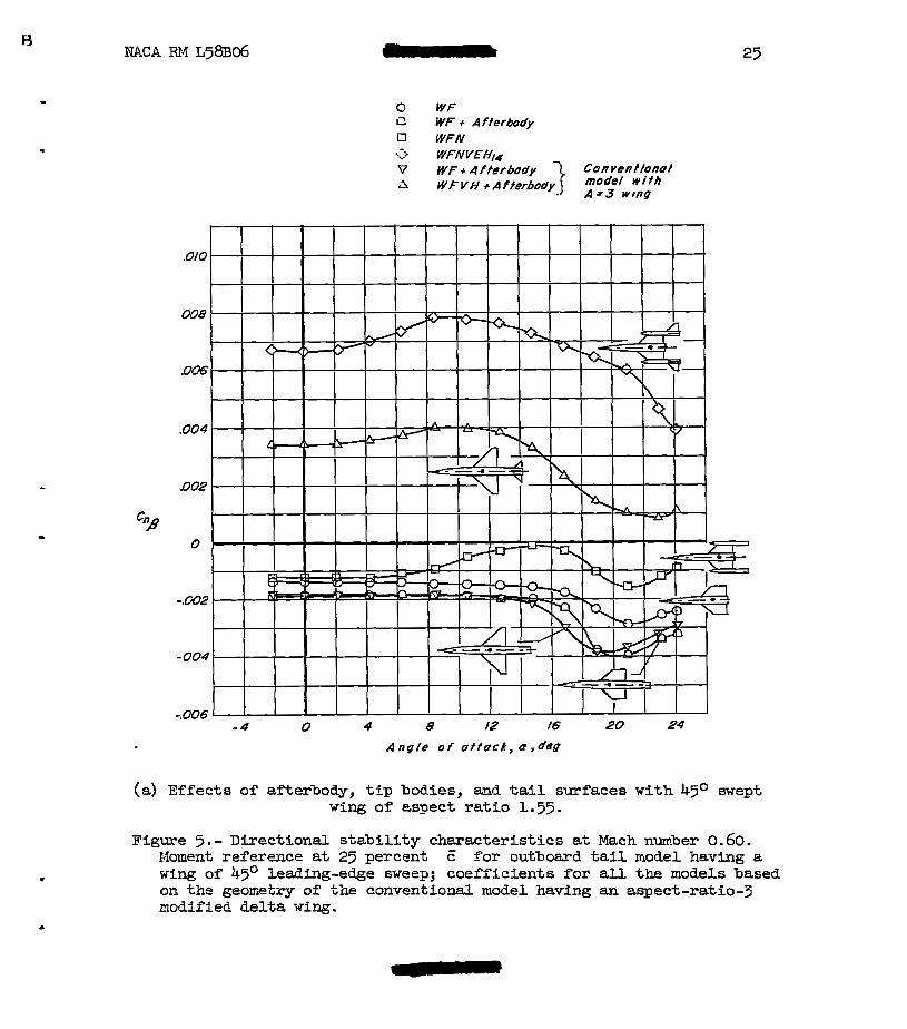
in d i rec t iona l s tab i l i ty at high angles of attack could be obtained with a three-body arrangenent w i t h the two r e w a r d bodies glaced out- board on the w i n g . The results of reference 7 have shown a l s o tha t renoval of the afterbody of highly swept wing-body configurations had a favorable effect on the direct ional s tabi l i ty at high angles of attack. Some experimental directioncl stability characteristics axe summarized i n figure 5(a) for both tail-on and tai l-off. In order to cumparre these resu l t s with the original wing-body configuration (ref. 6) from which the outboard t a i l roodel was derived, the coefficients for all the con- figurations aze based on the geoxetry of the aspect-ratio-3 modified delta wing. The t a i l -of f results for the 45' swept wing (fig. 5(a) ) show signif icant direct ional s tabi l i ty gain at high angles compared with the r e su l t s for a conventional aspect-ratio-5 wing-body configuration.
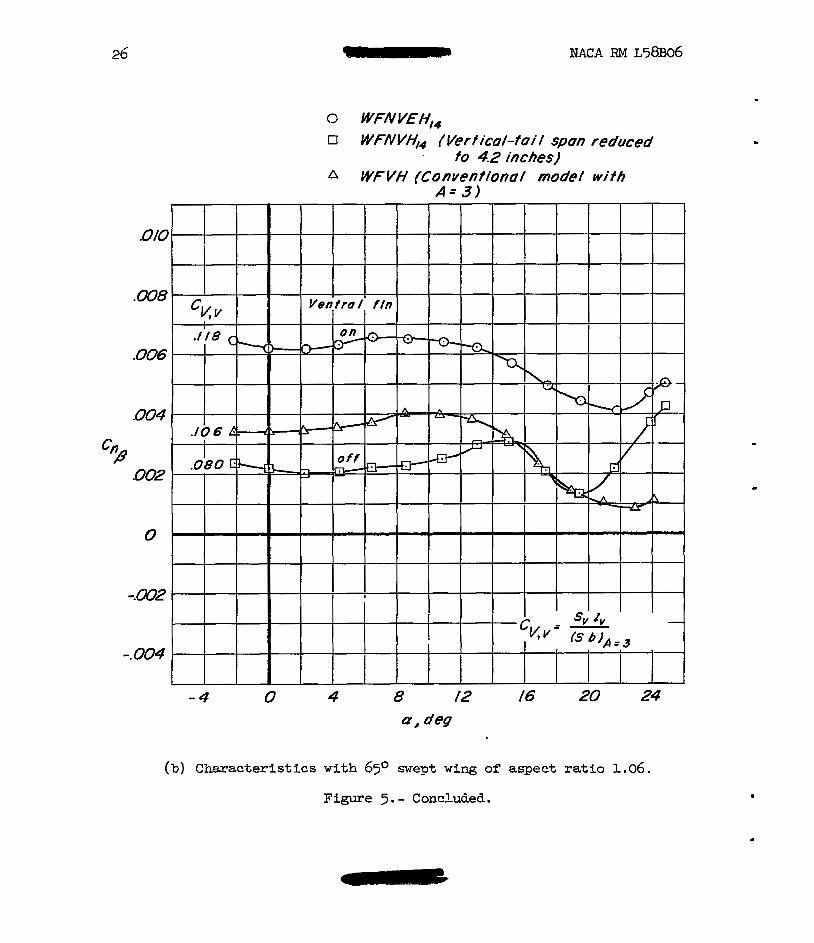
The tai l-on results of figure 5(a) show a high level of directional s t ab i l i t y fo r the outboerd t a i l =ode1 wi th a decrease i n occurring at high mgles of attack. These results are not directly compwable with thcse for the conventior-a1 model inasmuch as ventral f ins were instal led on the outboard t a i l model. Some resu l t s are presented in figure 5(b), however, fo r a similaz outbomd ta i l model having 65O sweep of the wing leading edge which show directional stabil i ty characterist ics with and without t he ven t r a l f i n s . nese results ( f ig . 5(b)) show the trends with ta i l volume at low angles of attack that would be expected *om the tail-volume coefficients given; however, at high angles of &tack t h e outboar& ta i l model which had l e s s t a i l volume had more directional s tabi l i ty than the conventional model. Test results presented in refer- ence 5 and unpublished data for e. configuration sixilar t o that shown in f igme 9 have incicated satisfactory directional stabillty character- i s t i c s at supersonic speeds f o r two outboazd ta i l configurations.
%
Lateral control.- The outboard location of the horizontal surfaces provides a relat ively long noxent m for producing rol l ing moments by differential deflection of these surfaces and it would be desirable t o consider this control aspect of outboayd t a i l 6,rrangements. Sone resu l t s are Srese l ted in f igwe 6 fo r Xcch number 0.60 to i l lus t ra te the lateral character is t ics to be expected with the horizontal surfaces deflected different ia l ly as r o l l producers. The nomine1 s tebi l izer set t ings of Oo m d -14' would represent apgroximately 7' of different ia l def lect ion fkom a basic t r i m se t t ing of -7O et 2. 10% mgle of attack, and the -140 and -25' stabi l izer set t ings would epply t o a basic longitudinal t r i m condFtion at e higher mgle of attack. Rolliag-moment results obtained w i t h t3.e Oo and -1ko stabi l izer set t ings show a fairly constant effec- tiveness cp t o about 10' angle 02 &tack, above which s t a l l i ng of the t a i l with Oo stabi l izer set t ing causes the effectiveness to decrease rapidly. Effects of negstive t a i l stall on the ta i l with the -25O set t ing are evident at low angles or" attack for the -14O and -25O s tab i l izer sett ings. A t high angles of attack, for the -latter combination, only

B NACA Rl4 ~ 5 8 ~ 0 6 9
about e 25-percent reduction ir rolling power from the low-m-gle-of- a t tack rol l ing power vas indicated. Another asDect of in te res t shown in f igure 6 i s the compmetively srdl.1 values of the ratio of yawing noment t o r o l l i n g xomer-t obtair-ed over the angle-of-atteck range wher- compmed with the t a i l roll control results of reference 8. The f ac t that the yawing moment c-hanges sign et high angles of a t tack ( f ig . 6 ) may be as undesirable as high yawiag momnts induced at low angles of attack; however, w i t h the stabilizer set t ings for t r i m (-14O and -25') at high angle of &tack the reversal xould be nuch less objectionsble t h m t h a t sl?oTm f o r the lower set t ings.
L l f t md Drag Characteristics
One of the main reasons f o r considering airplzne configurations having outboard tails is the possibil i ty that very small penalties or even favorable increments in L/D due t o trirrming may be obtained et supersonic speeds. The outboard location of the horizontal t a i l would be expected t o be favorable from the standpoint of drag due t o l i f t inas- wuch as the t a i l operates in t he upwash from the wing-tip vortex and would recover p m t o f the vortex energy as posit ive l i f t . This ef fec t nay be consiciered as increase i n effective aspect retio of the basic wing obtained by edding an undeflected outboard tail. Sone experimental d&te i l l u s t r a t ing t h i s effect are shown i-n figure 7 for the 45O swept- wing outbomd t a i l model. These r e s u l t s m e camparred w i t h the basic aspect-ratio-3 conventiocal model a" reference 6 and the coefficients are based on the geometry of the conventional nodel. These r e su l t s show tkt the outbomd t a i l nodel had the sme l if t-cvzve slope at low angles of attack as the basic aspect-ratio-3 model, znd at high angles of &tack the outbow6 t a i l model h a d higher values or" lift at a given mgle t-han the aspect-ratio-3 model. The wing and tai l of the 45O swept- wing outboard t a i l model were &erived -from t he parrent aspect-ratio-3 model by effectively cutt ing of f the t ips of the wiEg and t r a n s k t i n g them rearwad 011 the outer bodies t o form the tai l surfaces; t h i s gives the same theoretical totalpl&.n-fam mea. It would, therefore, eppeez that the surface mea w a s more effect ively placed in the rem- vard position where it could coctribute s t ab f l f ty and control labi l i ty rather thm acting as a wing t i p .
The drw results preseEted 5n figure 7 show that & reduction in drag due t o l i f t eccoqanied additio?l of the outboard tails; however, the drag due t o 1F1't of the outboaxd t a i l nodel w a s somewkt higher than the basic espect-ratio-3 model up t o moderately high l i f t coef'fr- cients. 4- further reduction Fn d-rag due t o l i f t Tor the outbomd ta i l =ran-gemen-k night be expected t o accompany aegetive deflection of the horizofitz.1 ta i l . -An explanation of the possible beneficial effect of negztive incideme on drag may be O'Dteined from the follo-ving sketch:

10
CDt
In this sketch, the w i n g i s operating at an angle of attack a, and the t a i l angle of a t tack in the upwash f ie ld of the wing t i p i s a - E f it. The tai l must, of course, carry a positive lift for trim in order t o have a beneficial effect on the l i f t -drag ra t io , and the resul tant force on the t a i l would be inclined forward for Fositive t a l l lift at a negative stabilizer sdtt ing (assming tha t the resultant force was normal t o the t a i l chord plane). This forward inclination of the resultant force on the t a i l has a forward cmponent in the streamwise direction corresponding t o a negative drag increment. ThFs concept may also be extended t o drag reduction by means of proper orientation of the twin vertical tails in the sidewash f i e l d from the wing-tip vortices. For this application a small amount of "toe out'' of the ver t ical tai ls might be beneficial; however, use of such a scheme for drag reduction would have t o be a casefully tai lored arrangement, possibly designed only for a cruise condition.
c
Experimental resu l t s of reference 5 obtained et a Mech nmber of 2.01 show the expected reduction i n drag due t o lift with negative inci- dence on the outboard tails. The drag polms and corresponding l i f t - drag r a t i o s from reference 5 are repeated in figure 8 of the present report. These results show significmt reductions in drw due t o l F f t i n going f r o m zero t o negative t a i l settings; however, the corresponding increase in minimurr. drag had a compensating effect on lift-drag ra t ios . The lift-drag ratios presented Ln figure 8 show a rela-bively small decrease i n (L/Dlnax for negative increments i n s tab i l izer settir?@;s from Oo t o -7.4O. These resul ts indicate that the maxim lift-drag r a t io s for the trimed conditions for the outbozrd t a i l configurations may be relatively insensit ive t o control deflection for moderate nega- t ive vslues of deflection. This would imply as indicated in reference 5

NACA TU4 ~ 5 8 ~ 0 6 11
that the maxtr~um trimrred lift-drag r a t i o s f o r the outbomd tail configu- ra t ion would be relctively insensit ive t o the mount of s t a b i l i t y f o r low and moderzte values of s t a t i c m r g i n .
Analytical Study of Effects of Some Design Vasiables
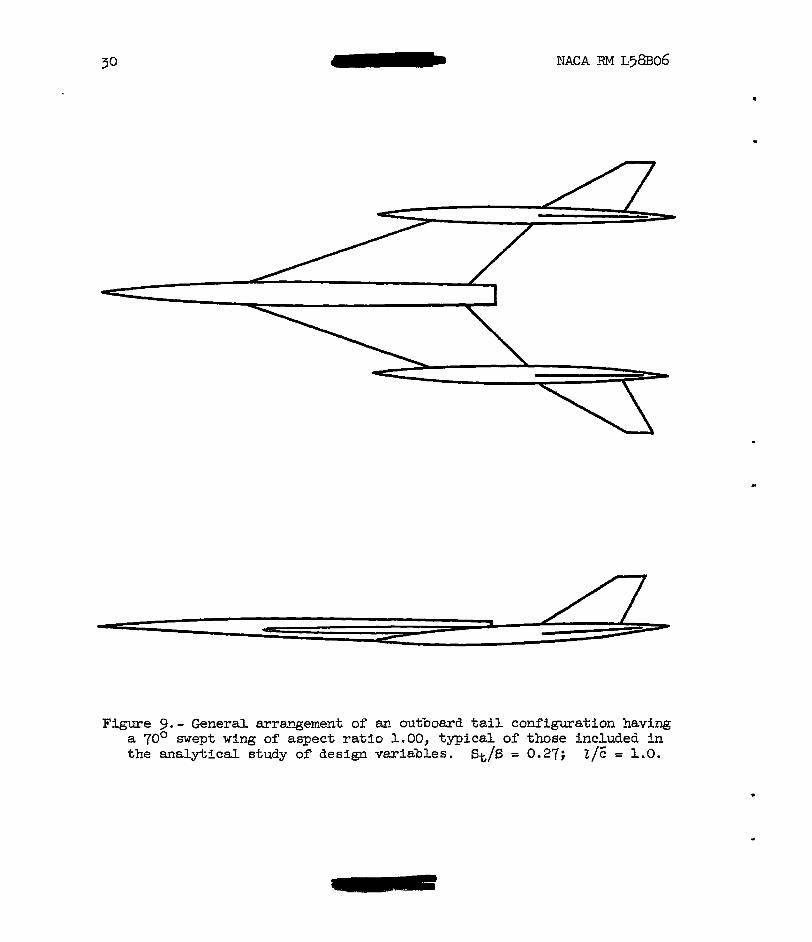
The general arrsngement of outboaxd t a i l corrfigu-rations i s so dif- ferent fro= current conventional airplane mrangements that cast experi- ence cannot be u t i l i zed w i t h confidence to def ine the most advantageous proportiom end arrangement of tne various individuel componeats from the stendpoint of performance. For this reason it Ls desirable t o deter- mine some overall trends frm ayproximte c&lculations of the eqec ted vwir t ion of maxinun lift-drag ratio with certain basic geometric m a aerodynamic parameters. A few estimates heve been made which show ef fec ts on t r i m e d (L/D)v,x of re la t ive s ize of the w i n g a d outboerd tails, effects of changes irt s t a t i c margin, and effects of the flow f i e l d in which t h e t r i l s operate. The various aerodynamic perameters chosen f o r the estimates were selected to represent values which might be Epplicable to a f l i g h t Mach nuzber o f 3.0. Inasmuch as these estimates were intended t o establish trends with certain basic geometric vartables, the magnitude of the estimated values i s not as significant as the t rends shown. The chzracterist ics indicated for some of' the outboard t a f l UrangeEents m e not necessarily unique to the outbomd tall configuration, m d other arrangements, such as 2 highly swept all-wing design, xay provide similer characteristics through careful desli_&n. Details of the procedures aad equatior-s used in the estima-les are given in the appendix. AD outboard t a i l cocfiguration is shorn- i n figure 9 t o i l lus t ra te the type of arrange- ment considered L n the estimates.
Effect of ?low f ie ld . - The vaziation of ugwash outboazd of %he wing tip as deternined by the theore t icd re la t ionships of reference 9 at M = 3.0 is presented in figure 10. This figure shows the eqec ted high values or" upwash ne= the wing t i p m-d the rapid dhinishuent of upwash .%way from the t i p . It is readily rppment that a short-span tai l out- bomd ol" the wing t i p -muld be T n a lazge upwash f i e l d and e. large-span horizontal tai l would be ic a much sxal ler overal l upwash field. Fig- ure 11 hzs been prepared t o i l lustrate efTects ol" flow f i e l d on trimmed
one wing xean aerodynamic chord and r a t io s of t a i l mea t o wing area of 10 and 20 percent. The different values of - shorn- might correspond
t o tails or" vmious spans o r to different pos5tions of the t a i l behimi the wing. For exmgle, positive values of - '' correspond t o conven-
t iona l cen ter t a i l s and negative values correspond t o tails outboard of
W D ) Im,X values for airpla?e corkfigurations -navi-ng e t a i l leEgth of
de aa
aa
.

the wing t i p . The overall trend of increasing values of (L/D) max as
- a s becones more negative is t o be expected, and the reduction in Lrirmned & (L/D)Ka with increased stability for the conditions of conventional configurations positive values of 2) is &so w e l l known. These esti-
mates a s o indicate the trends observed in the experinental results of reference 5 w i t h regard to e f f ec t s of s t a b i l i t y i n that a t negctive values of - trimxed (L/D)- values are relat ively insensi t ive to
the amount of s t a b i l i t y f o r s t a t i c margins between 0 and 10 percent E . This observation should apply t o t h e outboard t a i l configurations being
( a,
be da
considered inasmuch as values of & from -0.40 t o -0.60 averaged Over da. t he t a i l span have been calculated. The trends of (L/D),= with changes in stabllity indicated in these estimates were substantiated experimentally at M = 2.01 i n the results of reference 5 . Because of the low s e n s i t i v i t y t o the mount of stabil i ty, relatively high super- sonic s tabi l i ty probably could be tolerated from considerations of trimmed (L/D),=. Thus, the problems introduced by the s tab i l i ty change, i n going fron subsonic t o supersonic speeds may be less serious than for some other designs.
"
Effect of horizontal-tail size.- One of the most inrportmt variables t o consider i n achieving an ef f ic ien t outbomd t a i l arrangement i s the re la t ive s i z e of the w i n g and horizontal t a i l surfaces. This relation- ship has a direct effect on the s t ab i l i t y and col t ro l lab i l i ty of a given wing-body arrangement and upon the permissible center-of-gravity loca- t ions for given stabil i ty levels. The t a c i t assumption made in the estimates Tor the outboard t a i l configurations is that for the cruise condition an upload is carried on the t a i l surfeces when the aircraTt i s in longitudinal trim. The t a i l surfaces then me contr ibut ing to the airplane l i f t and m y be considered a part oI" t h e t o t a l l i f t i n g surface area. For this reason, the t o t a l area of the wiEg plus t a i l w a s held constant Tor t'ne gresent calculations as the ra t io of tai l area t o wing area w a s varied. The p1m forms of both the wlng and to.51 rermined the same when the area ratio vasied; however, the effective upwash over the t a i l was detem-ined frm the curve of upwash presented i.n- figure 10 for each size t a i l . The values of effective Epwash used were -0.627, -0.479, and -0.401 f o r r a t io s of t a i l area t o wing area of 0.1, 0.2, md 0.3, respectively. Estimated effects of the ratio of tai l ere= t o wing area on m a x i m u m L/D presented in figure 12 show e. general increase in trimmed (L/D),, with increasing t a i l size. As shown previously, there is l i t t l e e f f e c t of s tabi l i ty within a certain range of s t ab l l f ty valries. A significant l o s s i n (L/D)mG was
NACA RV ~ 5 8 ~ 0 6 13
.
indrcsted at low vdues of t he r a t io of t a i l mea to wing wee for %331 increase in static =gin from -0.10 t o -0.20; however, th i s loss WES greatly diminished for higher values of tail-&re&-wing-area ra t io .
K f e c t of t a i l 1eWth.- The estimates of ezfects of t a i l s ize were extecded t o Essess the influence of tai l length for two values of tail- me=-wing-mea ra3io. Results from these estimtes presented i n f i g - ure 1-3 show thzt an overall increase in t r b n e d (LP)- occurred with increasing t a i l le&h for negative vdues of -. ac, The results
show also tkrzt, for values of 5 betweer- 0 and -0.10, l i t t l e gain in
(L/D)ma would be expected Zron fncreeses in t a i l length ebove Z / E = 1.0 for the arangexents beiEg considered.
aCL
ac,
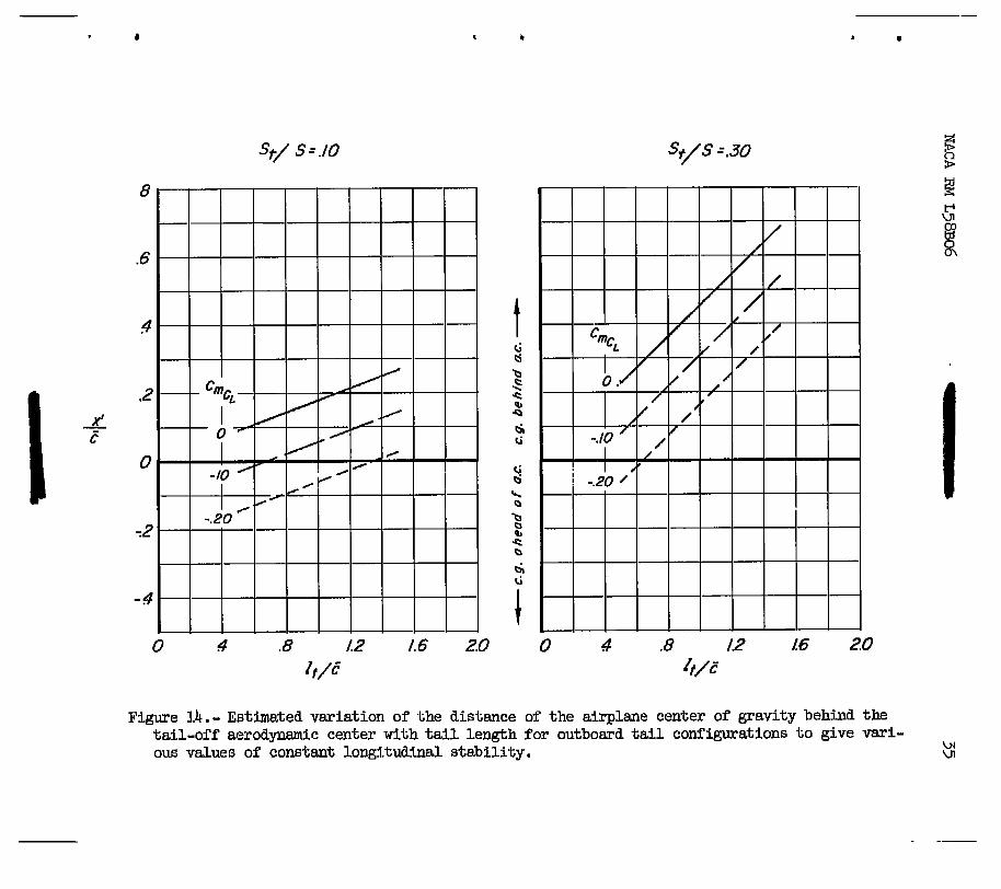
The estimates th&t have been considered hzve indiczted ra ther lmge changes in configuration proportions f o r given constant values of sta- b i l i t y . These constant vslues of s t ab i l i t y were achieved i n the esti- mztes by chmging the distance between the wing-body aerodynmic center m d the reference center of gravity the required mount for the t a i l contribution of each configuration. This type of adjustxent i s useful in assessiF4 overal l effects in computations; however, oot d l of the combinations giving e constant value of s t a b i l i t y may be realist ic fo r pract ical app1ice;tion t o airplane. Figure 14 presents the variation of' the distance betxeen the tail-off aerodyamic center and center of grevity w i t h both teil-area-wing-area r&t io and tai l l e w h f o r t h e three values of s t zb i l i t y used i n t h e e s t b a t e s . The relationships presented "m figure 14 show large variations i n x*/E fo r the conditiom covered in -ih~ estimates. Fairly large positive values of x'/E might be expected t o eccornpany configurations w i t h r emerd placed engine installehions; however, large positive values of x ' / E woud aggrwate the problen of ettaining sufficient n?oxe?lt mm for the ver t ical tizil. Very s m d l sositive or negztive values of x'/E would be favordole fron the standpoint of ver t ica l - ta i l moment arm; however, a forward center- of-gravity location would probably not be fzvorably located IYOm con- sicieratioc ol" pitching moments resul t ing from deTlection of t ra i l ing- edge l i f t f lzps. These two factors axe, of course, obvious examples of' may factors that enter into determination of am overall configuration, but they illustrate possible limitations thzt could require selection of 8 cocfigunstion smkewha.t less desirable thax indicated as optimua.
Elfect of i n i t i a pitching moment. - The t a F l loed requLred for trim is a function of the tail-or"? pitching monent, -which u s ~ ~ J l y varies w i t h mg le of attack, m d any d d i t i o n a l i n i t i a l p i t c h i n g moment exis t icg at zero l i f t . The e s t h e t e d results discussed so f a have not included the latter effect which is consLCere& i-nvariant with mgle of attack. Some

14 NACA RM L58-
additional estimates have been m&e t o i l l u s t r e t e the possible effects on trimmed (L/D),, of using values of Cn0 other than zero and the resu l t s of these estixgtes are presented in figure 15. The a s s u ? t i o n was made fo r these calculz;tions that the various values of Cmo were achievable w i t h no change in CD or CL. These estinates show tht fo r a given amount of s tabi l i ty there is a value of Cmo which gives a peak value of trimmed (L/D)=. Furt‘nermore, it appears that the peak values of (L/D)max axe the same fo r eech &?iaunt of s t ab i l i t y investigated; this suggests that there are many combinations of and s t ab i l i t y which would be expected to give the same m a x i m u m value of trimmed (L/D),, for a particular outboard t a i l configuration.
Thfs chmacter is t ic of conbinations of C and may be ut i l ized
t o approach more closely an optimum arrangement which might otherwise be unattainable because of the practical limitations discussed earrlier.
cmO
mo ac,
CONCLUDING IiEMARKS
A prelim5nary study of airplane configurations having the t a i l sur- faces located outboard of the wir-g t i p s mey be suxmzized in the fo l - lowing observations.
1. Experimental results indicated tbt location of the horizontal- ta i l surfaces in the u?wash f i e l d of the wing-tip vortices would be expected t o be favorable from the standpoint of trimmed liIft-drag ratios at subsonic and supersonic speeds.
2. Pitching-moment curves fo r an outbomd ta i l model showed gra& ually increasing stabil i ty with lift up t o a lift coefficient of approxi- nately 1.0 at a M&ch nmber 0.60, above which a pitch-up tendency was indicated. These and other data indicate a possible longitudinal sta- b i l i t y problem fo r outboard t a i l configurations which i s believed. t o be associated with Ins tab i l i ty caused by loss of upwash when the wing-tip vortex becones disglaced et high angles of attack.
3 . Indications axe that outboard tail configurations would be expected t o have sat isfactory direct ional s tabi l i ty character is t ics at both subsonic and supersonic speeds.
4. An analytical study at Mach number 3.0 of effects of design veriables has indicated that values of trimmed m a x h u m lift-drag ra t io s were relat ively insensi t ive to the amount of s t a b i l i t y f o r s t a t i c rnazgins
between 0 and 10 percent m e a aerodynamic cbm-d. The trends indicated in these est7h-bes were verified experimentdly at M = 2.01. Introduc- t i on of a small amount of pitching moment E t zero lift may be used t o compensate Tor losses in L/D occurring as a r e su l t of somevhat higher s t ab i l i t y .
5. This analysis a lso indicated graciuzl increese i n trimmed (L/D)mEx with both t a i l length and tail s i ze ; however, increases w i t h tai l length were generally quite small for lengths i n excess or” about one wing xeen chord.
Langley Aerol?autic.z?,l L&bor&tory, Kational Advisory Comittee f o r Aeronautics,
Lengley FTeld, Va., Jenuary 13, 1958.
.

16 NACk RM ~ 5 8 ~ 0 6
FSLATIONSHIPS USED I N ESTIMATION OF LIF'T-DRAG RATIOS
The equation used in estimating the effective upwash over the out- board horizontal tai l was derived from reference 9 and is
r
where 5 is assumed to be unity for present coqutations and CLCav
wing average chord
C wing l if t-curve slope, radians LU
m cotangent half -chord sweep angle
X distance r e w a r d from epex of swept l i f t i n g ILns ir? terms of wing senisgan
Y spanvise distance from plane of syrmetry i n terms of wing sernispm (considered positive for r igh t wing)
.
Use of eo_uai;ion (1) gives values of % along the span of the
ta i l . Vdues of effective upwash over the t a i l were obtained f'ron! inte- graticn of the Product of local 2 an8 local chord &cross the t a i l
ba span.
da

B
The I"ollow5ag approximate reldAonships were used ia estimations of trbed (L/D)nu. The symbol notation is the same as th=t given in the body of the report end only symbols not previously deZined w e defined in this appendix.
The total airplane lift, drag, m d pitching-moment coefficients can be represented by the following expressions:
c, = cmo + UC&f X - CL,t 2 $ cos E where
lift-curve slope of tail-off configuretion
C drq coefficient at zero lift of tail-off configuration DO
%lo pitching-moment coefficient at zero lift of teil-off collfiguration
t horizontal-tail surfaces
For low engles of attack, at least t o values corresponding to (L/D)-, the assunption that cos E: = 1 and sin E = E should be permissible. Substitution of these assumed values into the foregoing lif%-, drag-, and pitchirg-xoment-coefficient expressions gives:

18
The tail load required f o r trim is given by the following expression:
Values of C determined and (3) . The static margin as
L, t f r o m equation ( 5 ) w e used in equations (2) for a given arrangenent can be expressed
m 1
The distance between the tail-off aerodynamic center and center 02 gravity required for a given static mrgin is given by
The aerodynamic and geonetric parameters used in the preceding equations are included hereir, for completeness m d are not necessarily associated with any particular outboard tail configuration. Two sets of constants were used in the calculations. The constants associated with the results of figure 11 are identified as configurction 1 and .. those associated with figures 12 to 15 are identified as configuration 2.

NACA FM ~58B06
dCD For both conditions, the drw-due-to-lift pesameter - for the wing
2CL2 or tail was assuxed equal to the reciprocd of the wing or tai l lift slope. The constents are presented in the following table:
Coz?figurat io2 1
1.30
. 0100
.0060
77
87
1 .o
0
Configmation 2
1.312
. 0100
.0060
70
al.O
“0
% w e p t as indicated in the figures.

20 NACA RM L58B06
1. Spearmen, M. Leroy: Sone Fectors Affecting the Static Longitudinal and Directional Stability Characteristics of Supersonic Aircraft Configurations. NACA RM L57E24a, 1937.
2. Driver, Cornelius: Longitudinel and Lateral Stabi l i ty and Control Characteristics of Two Canasd Airplane Configuretions at Mach Iiumbers of 1.41 and 2.01. NACA RM ~ 5 6 ~ 1 9 , 1957.
3 . Sleerrm, Willism C . , Jr. : An Experimental Study at High Subsonic Speeds of Several T a i l Cortfigurations on a Model Having a 450 Sweptback Wing. NACA RM ~ 5 7 ~ 0 8 , 1957.
4. Fownier, Paul G.: Low-Speed Investigation of Static Longitudinal and Lateral Stabil i ty Characterist ics of m Airglane Configuration With e, Highly Tapered Wing and Witn Several Body an& T a i l Prrangernents. NACA RV L57AO8, 1957.
5 . Spearman, M. Leroy, and Robinson, Ross B. : Aerodynamic Characteristics of a Canard and an Outboard-Tail Airplane Model at a Mack? Nurrber of 2.01. IUCA RM ~ 5 8 ~ 0 7 , 1958.
6. Few, Albert G., Jr.: Investigation a t High Subsonic Speeds of the S ta t ic Lateral and Directional Stabil i ty md Teil-Loads Character- ist ics of a Model Having a Highly Tapered Swept Wing of Aspect . Ratio 3 and Two Horizontal-Tail Positions. NACA RM ~ 5 6 ~ 2 9 , 1956.
7. Polhamus, Edward C. , and Spreemann, Kenneth P.: Subsonic Wind-Tunnel Investigation of the Effect of Fuselage Afterbody on Directional S tab i l i ty of Wing-Fuselage Canbinations at High Angles of Attack. NACA TN 3896, 1956.
8. Cmpbell, John P. : The Use of the Horizontal T a i l for Roll Control. NACA RM ~55~16=, 1956.
9. Martin, John C. : The Calculation 02 Dovnwesh Behind Wings of Arbitrary Plan Fom at Supersonic Speeds. NACA TN 2135, 1950.

NACA RM ~58Bo6 21
r Loteral farce
Pftchfng moment
A Ro I f iag moment
if
Yawing moment
1
Figure 1.- Body rer"ererce axes showing positive directions of forces, moznents, m d angulaz deflections.

22 NACA Rlrl L58B06
72 -. / 0 ./ .2 3 4 .5 .6
Figure 2. - Pitching-zoment characterist ics of m outboard ta i l model having s 67O sdept wing cf aspect ratio 1.00, with neutral stctbilizer setting at Xach nm-bers of 0.90 and 2.01. Date for M = 2.01 obtained from reference 5 . blm-ent reference et 50 percent E ; coef- f ic ien ts based on geometry of w i n g and horlzontal tail.

Figwe 3. - Pitching-moEent character is t ics of m- oatboard tail m o d e l hzvrng a 4 5 O svept wing 02 aspect m t i o 1.55, with and without tail surfaces &e M = 0.60. Mozcent reference at 25 sercent E; coeffi- cients based on geometry of w i n g .

L NACA RM L58B06
-4 0 4 8 /2 /6 20 24 0 I deq
Figure 4.- Variation of effective upwash angle with angle of at tack as dete,rnined from experLTenta1 pitching-xorent data for the outboard
.
w NACA RM L58B06
- 4 4 8 12 16 20 24
A n g l e o f o f t u c k , a, deg
(a) Effects of efterboiiy, tLp bodies, and t a i l surfaces w i t h 45O swept w i n g of essect r a t i o 1.55.
Figure 5.- Directional stzbility chmacter i s t ics at Mmh nunher 0.60. Homent reference a t 25 percent c' for outboard t a i l nodel having e. wing of 45' leading-edge sweep; coeff ic ients for all the models based on the geonetry of t h e conventioml model having an aspect-rgtio-3 modified delta wing.
26 NACA RM L58BO6
0 WFNVEH,, L7 W F A W Y , ~ fVertica/-tai/ spun reduced
. to 4.2 inches) A WFVH (Convenfiona/ mode/ wifh
A= 3)
(b) C:macteristics with 65O swept wing of aspect ratio 1.06.
Figure 5.- Conchied.
.

"
-5 0 5 10 15 20 25 30 Angle o f attack I Q , deg
. Figure 6 . - Latersl conk01 characterist ics of the outboard t a i l model
havfng a k5O swept vir4 of aspect ra t io 1-35, vith the horizontal t a i l s deTlected differentially. M = 0.60; f4 = Oo; moment reference at 25 percer-t c; coefficients based on geometry of wzng. -
4

Configuratron
.* WF (A-31 S WF
0 WFNVEHo n WFN
I Figure 7.- Summary of the lift and drag-due-to-lift characteristics of the outboard t a i l model
having a 45' swept wing of aspect r a t io 1.55 at M = 0.60. All coefficients based on geome- t r y of the conventional model having an aspect-ratio-3 modified delta wing. cn
L 0

-.2 -. / .I .2 .3 4 .5 CL
t
Figure 8.- Effects of s tab i l izer se t t ing on drag coefficients and l i f t - cirw ratios Tor &E outboard ta i l model having a 67O swept wing of aspect ra t io 1.00 at, M = 2.01. Datz obtained from reference 5 . .
U
PACA “4 ~ 5 8 ~ 0 6
Figme 9. - General arrargenent of an, out’board t a i l configuration having a TO0 swept wing of aspect r a t i o 1.00, typical of those included i n the analy-tLcal study of design variables. S-t;/S = 0.27; 2/.’ = 1.0.
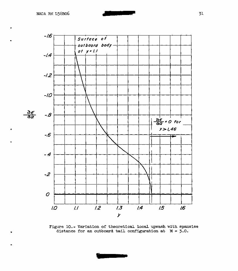
Figure 10.- Variation of theoret ical local upwash w i t h spa-wise distance for an outbcud tail c o ~ i g u r a k i o n at M = 3 .O.

s+/ s E .IO
Figure 11. - Estimated vaziation of trimmed with - and s ta t ic margin for airplane
configurations having tail surfaces located behind the wing, 2/c = 1.0.
a€ a,

8
7
6
5
2
/
0
. /u ./5 20 .25 -30
Sf/S
Figure 12.- Estinated vaziation of trimxed with ra-iio of t a i l
mea t o wing m e a Tor outboard ta i l configurations having a t a i l length of Z/c' = 1.0.

Sf/ s =.IO st/s=.30 w -F
0 A .8 12 1.6 2.0 0 4 -8 1.2 16 2.0 W E If/ 5
Figure 13.- Estimated variation of trimmed with tail length for outboard ta i l
configuration.
w 03 r
I . J I 4
I b I
8
.6
.2 X' i; -
0
12
- 4
Sf/ S=.lO
4 .8 l.2 I. 6 2.0
Figure 1.4.- Estimated vmiation of the distance of the airplane center of gravity behind the tail-off aerodynamic center with t a i l length for outboard t a i l configurations t o give vari- ous values of constant longitudinal stability. w
UI

8
7
6
5
0
Sf/ s = .IO
702 0 .02 .04 .06
cmo
I? u1
Figure 15. - Estimated variation of trimmed with initial pitching moment at zero lift
for outboard ta i l configurations having a tai l length of 2 / E = 1.0. 8 8