Embed Size (px)
Citation preview
Instruction manual SMART 96-2 / WG-2 LF
Stand: 06.09.2015
Off /OnEC/ Temp.
LimitAlarmPRIPRF
Displaymeasurement valuexx.xx µS / xxx.x mS
CONFIG 1
CONFIG 2
CONFIG 3
CONFIG 4
CONFIG 5
LANGUAGE
TEMPERATURE
DISPLAY
CHANNEL 1RELAIS 1
CHANNEL 2RELAIS 2
CHANNEL 3RELAIS 3
ANALOG 1
ANALOG 2
GermanEnglish
TemperatureOff / On
°C / Alternation
DisplayµmS / Ohm
EC / Temp.0...20 mA4...20mA20 mA
Off / OnEC/ Temp.
LimitAlarmPRIPRF
Off / OnEC / Temp.
LimitAlarmPRIPRF
EC / Temp.0...20 mA4...20mA20 mA
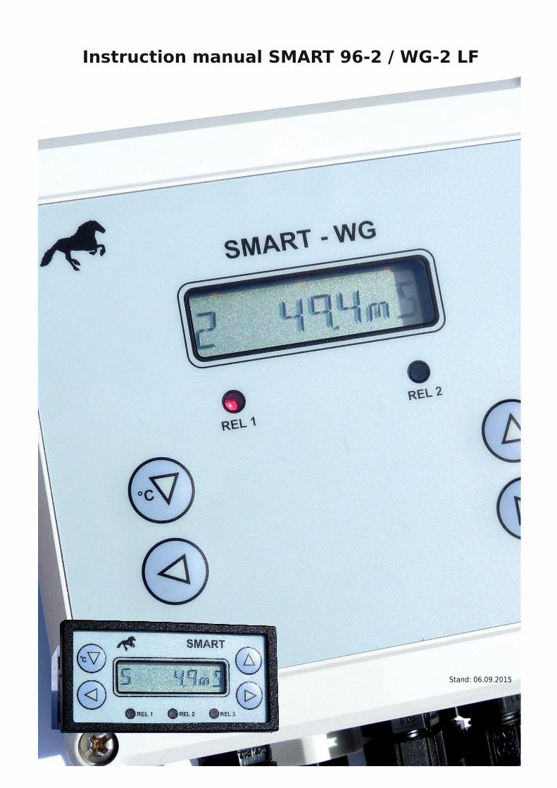
Connected temp. sensor → select temperature = ON.
Temp. display, alternating with pH-mV or by pressing ° C
Select measurement µS- mS / Ohm
CHANNEL Off / On, Assignment to µS / mS or temperature
Channel function: limit control, alarm, proportional control pulse, frequency proportional control
Current output 0/4 ... 20mA, assignment to E.C. or temperature
CONTRASTsetting
START
°C
SMART 96-2 / WG-2 conductivityInstructions for Installation
Configuration CONFIG 1
Back with this button
Switching the displayon temperature
We recommend, to activate the alarm in CHANNEL 3, if it is possible.
LIMIT HYSTERESE
Displaymeasurement value
CONFIG 1
CONFIG 2
CONFIG 3
CONFIG 4
CONFIG 5
CHANNEL 1
CHANNEL 2
CHANNEL 3
ANALOG 1
ANALOG 2
LIMIT
RELAISDuration / wiper
LIMIT
HYSTERESE
Off delay
On delay
SETPOINT
I-ControlOff / On
SETPOINT
PERIOD- DURATIONT in sec.
Max. DOSAGE
SETPOINT
I-ControlOff / On
SETPOINT
FREQUENCYin Hz
Max. DOSAGE
LIMIT
ON DELAYin min.
SIGNALon / off
LIMIT FUNCTION PRI PRFALARM
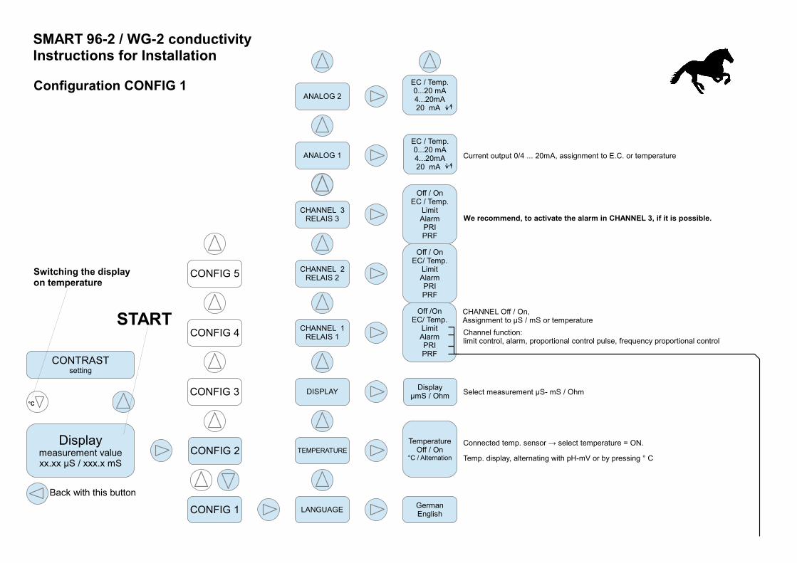
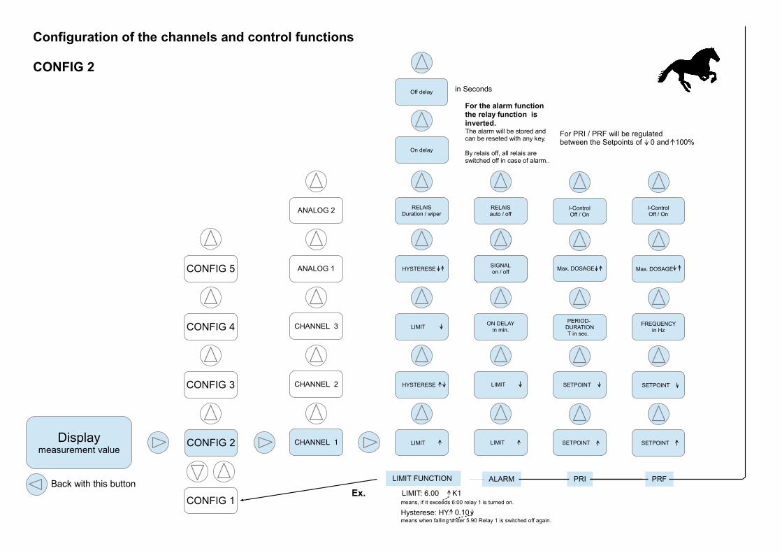
Configuration of the channels and control functions
CONFIG 2
in Seconds
For PRI / PRF will be regulated between the Setpoints of 0 and 100%
For the alarm function the relay function is
inverted.The alarm will be stored and can be reseted with any key.
By relais off, all relais are switched off in case of alarm..
Back with this buttonEx. LIMIT: 6.00 K1
means, if it exceeds 6:00 relay 1 is turned on.
Hysterese: HY.means when falling under 5.90 Relay 1 is switched off again.
0.10
SIGNALein / ausSIGNALon / off
RELAISauto / off
Displaymeasurement value
CONFIG 1
CONFIG 2
CONFIG 3
CONFIG 4
CONFIG 5
CHANNEL 1
CHANNEL 2
CHANNEL 3
ANALOG 1
ANALOG 2 LIMIT= 0/4/20mA
LIMIT= 0/4/20mA
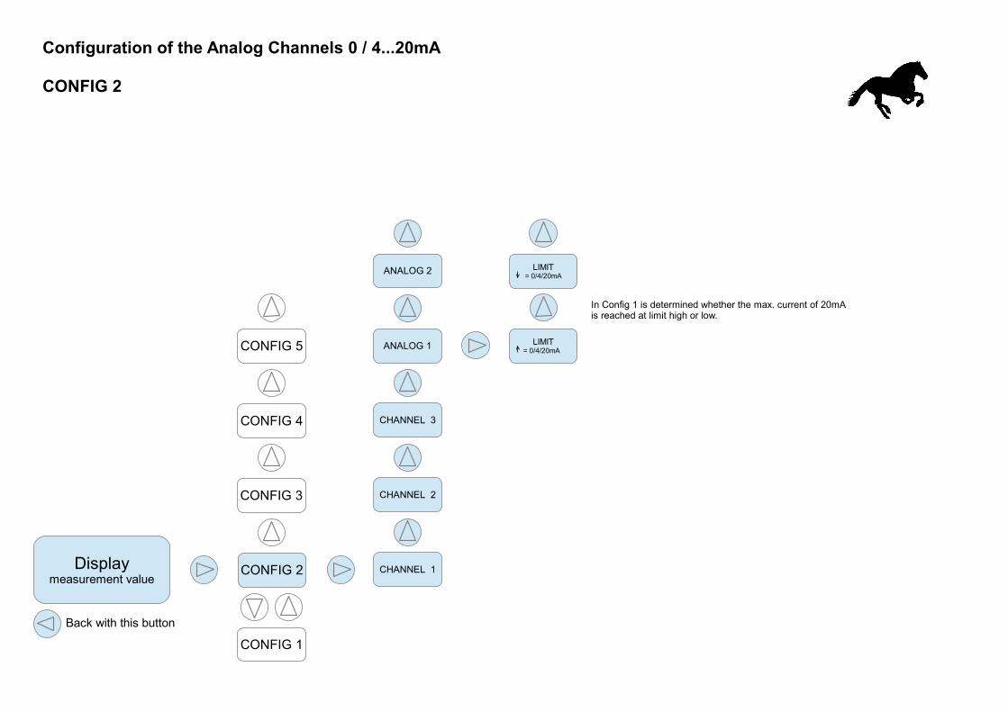
Configuration of the Analog Channels 0 / 4...20mA
CONFIG 2
Back with this button
In Config 1 is determined whether the max. current of 20mAis reached at limit high or low.
Displaymeasurement valuet
CONFIG 1
CONFIG 2
CONFIG 3
CONFIG 4
CONFIG 5
CHANNEL 1
CHANNEL 2
CHANNEL 3
ANALOG 1
ANALOG 2
AUTO / ON /OFF
AUTO / 0...20 mA
AUTO / ON /OFF
AUTO / ON / OFF
AUTO / 0...20 mA
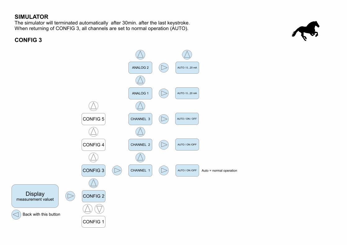
SIMULATORThe simulator will terminated automatically after 30min. after the last keystroke.When returning of CONFIG 3, all channels are set to normal operation (AUTO).
CONFIG 3
Auto = normal operation
Back with this button
Displaymeasurement valuet
CONFIG 1
CONFIG 2
CONFIG 3
CONFIG 4
CONFIG 5
Security lock codefor CONFIG 1 / 5
Security lock codefor CONFIG 2
SoftwareVersion No.
EquipmentNo.
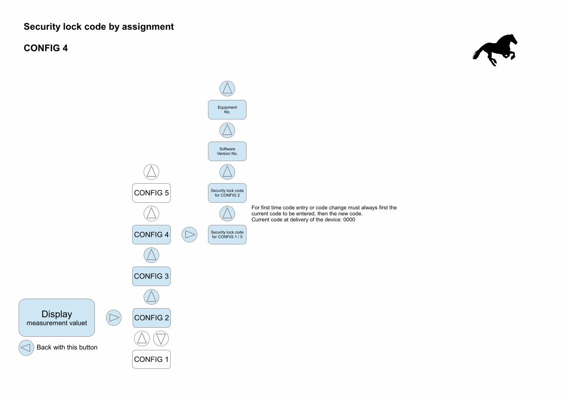
Security lock code by assignment
CONFIG 4
Back with this button
For first time code entry or code change must always first thecurrent code to be entered, then the new code.Current code at delivery of the device: 0000
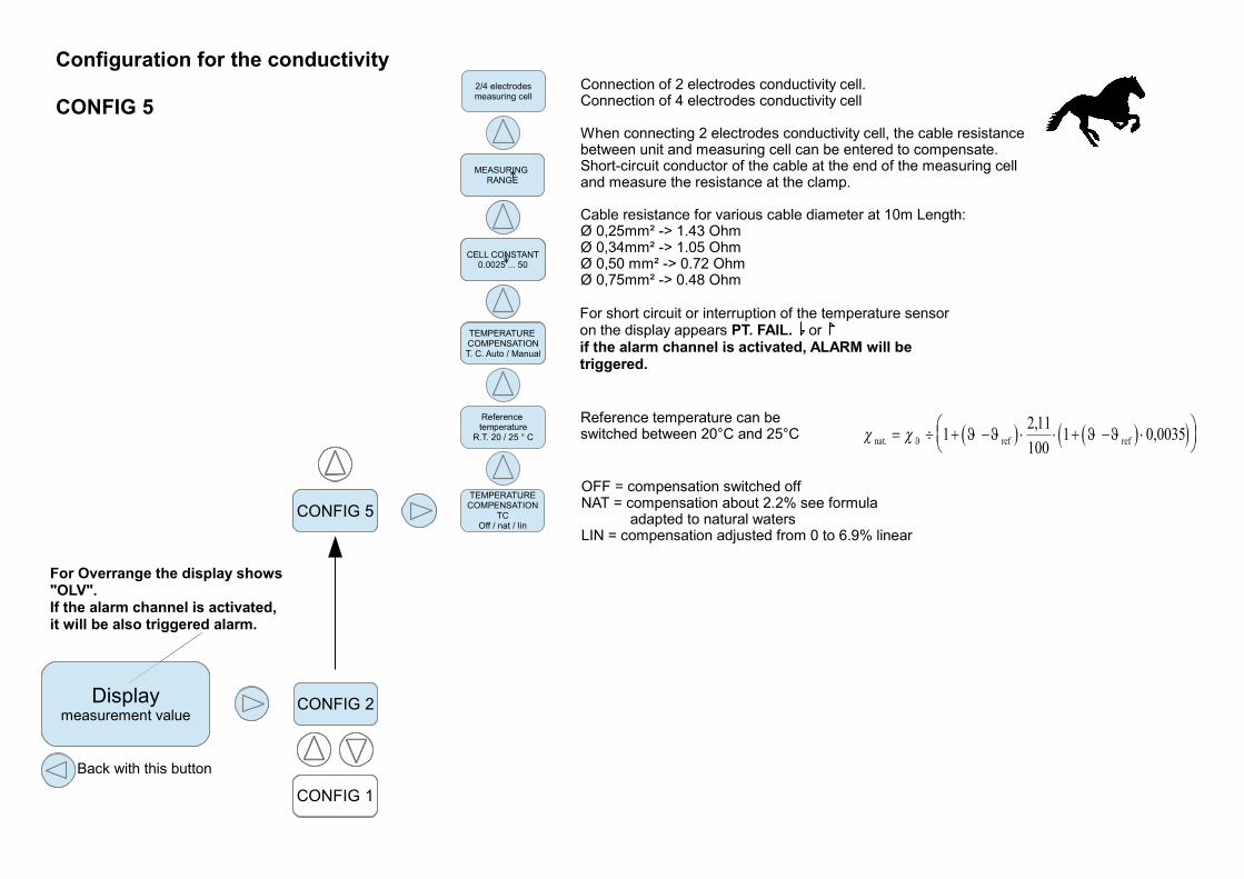
OFF = compensation switched offNAT = compensation about 2.2% see formula adapted to natural watersLIN = compensation adjusted from 0 to 6.9% linear
Displaymeasurement value
CONFIG 1
CONFIG 2
CONFIG 5
Reference temperature
R.T. 20 / 25 ° C
PUFFERNULLPUNKT
pH-KALIBRIERUNG
PUFFERSTEILHEIT sauerPH-KALIBRIERUNG
PUFFERSTEILHEIT basisch
pH-KALIBRIERUNG
Configuration for the conductivity
CONFIG 5
TEMPERATURECOMPENSATION
TCOff / nat / lin
Back with this button
For Overrange the display shows"OLV".If the alarm channel is activated,it will be also triggered alarm.
Connection of 2 electrodes conductivity cell.Connection of 4 electrodes conductivity cell
When connecting 2 electrodes conductivity cell, the cable resistance between unit and measuring cell can be entered to compensate.Short-circuit conductor of the cable at the end of the measuring cell and measure the resistance at the clamp.
Cable resistance for various cable diameter at 10m Length:Ø 0,25mm² -> 1.43 OhmØ 0,34mm² -> 1.05 OhmØ 0,50 mm² -> 0.72 OhmØ 0,75mm² -> 0.48 Ohm
Displaymeasurement value
CONFIG 2
CONFIG 5
TEMPERATURE COMPENSATIONT. C. Auto / Manual
PUFFERSTEILHEIT sauerPH-KALIBRIERUNG
MEASURING RANGE
Displaymeasurement value
CONFIG 2
CONFIG 5
2/4 electrodesmeasuring cell
CELL CONSTANT0.0025 ... 50
Reference temperature can be switched between 20°C and 25°C
For short circuit or interruption of the temperature sensoron the display appears PT. FAIL. orif the alarm channel is activated, ALARM will betriggered.
nat. ref ref12,
1001 0,0035
11
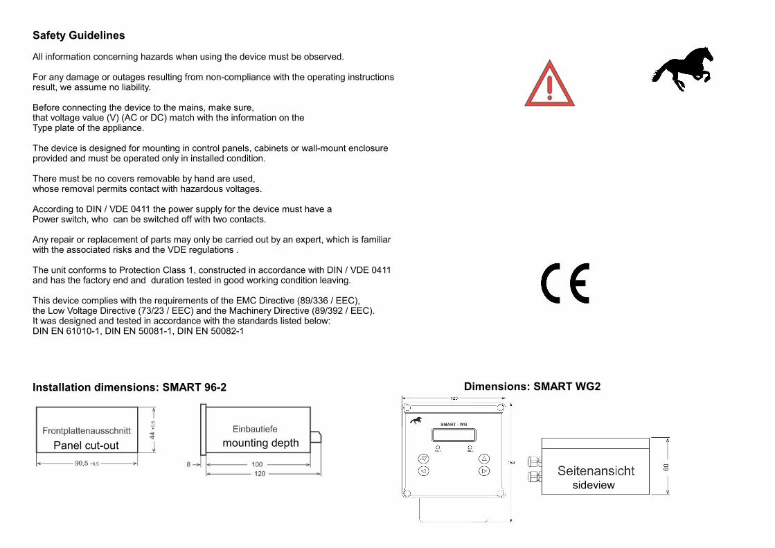
Safety Guidelines
All information concerning hazards when using the device must be observed.
For any damage or outages resulting from non-compliance with the operating instructionsresult, we assume no liability.
Before connecting the device to the mains, make sure,that voltage value (V) (AC or DC) match with the information on theType plate of the appliance.
The device is designed for mounting in control panels, cabinets or wall-mount enclosureprovided and must be operated only in installed condition.
There must be no covers removable by hand are used,whose removal permits contact with hazardous voltages.
According to DIN / VDE 0411 the power supply for the device must have a Power switch, who can be switched off with two contacts.
Any repair or replacement of parts may only be carried out by an expert, which is familiarwith the associated risks and the VDE regulations .
The unit conforms to Protection Class 1, constructed in accordance with DIN / VDE 0411 and has the factory end and duration tested in good working condition leaving.
This device complies with the requirements of the EMC Directive (89/336 / EEC),the Low Voltage Directive (73/23 / EEC) and the Machinery Directive (89/392 / EEC).It was designed and tested in accordance with the standards listed below:DIN EN 61010-1, DIN EN 50081-1, DIN EN 50082-1
Dimensions: SMART WG2
Panel cut-out mounting depth
sideview
Installation dimensions: SMART 96-2
SMART 96-2 / WG-2 LF
NETZ MAIN
2.2 2.1
1.17 1.16 1.15 1.14 1.13 1.12 1.11 1.10 1.4 1.3 1.2 1.1
A1 - + - + A2
Rel3 Rel2 Rel1
1 243
Pt100
2.10 2.11 2.09 2.7 2.8 2.6 2.4 2.5 2.3
SMART96-2 LF1
3 wire
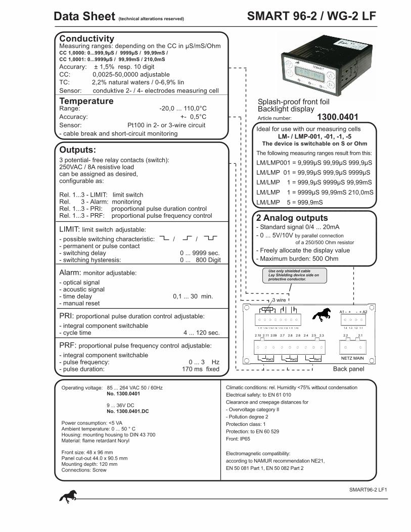
Data Sheet (technical alterations reserved)
ConductivityMeasuring ranges: depending on the CC in µS/mS/OhmCC 1,0000: 0...999,9µS / 9999µS / 99,99mS /
CC 1,0001: 0...9999µS / 99,99mS / 210,0mS
Accurary: ± 1,5% resp. 10 digit
CC: 0,0025-50,0000 adjustable
TC: 2,2% natural waters / 0-6,9% lin
Sensor: conduktive 2- / 4- electrodes measuring cell
TemperatureRange: -20,0 ... 110,0°C
Accuracy: +- 0,5°C
Sensor: Pt100 in 2- or 3-wire circuit
- cable break and short-circuit monitoring
Outputs:3 potential- free relay contacts (switch):250VAC / 8A resistive loadcan be assigned as desired,configurable as:
Rel. 1...3 - LIMIT: limit switchRel. 3 - Alarm: monitoringRel. 1...3 - PRI: proportional pulse duration controlRel. 1...3 - PRF: proportional pulse frequency control
LIMIT: limit switch adjustable:
- possible switching characteristic: / /- permanent or pulse contact- switching delay 0 ... 9999 sec.- switching hysteresis: 0 ... 800 Digit
Alarm: monitor adjustable:
- optical signal- acoustic signal- time delay 0,1 ... 30 min.- manual reset
PRI: proportional pulse duration control adjustable:
- integral component switchable- cycle time 4 ... 120 sec.
PRF: proportional pulse frequency control adjustable:
- integral component switchable- pulse frequency: 0 ... 3 Hz- pulse duration: 170 ms fixed
Splash-proof front foilBacklight displayArticle number: 1300.0401
Ideal for use with our measuring cells
LM- / LMP-001, -01, -1, -5The device is switchable on S or Ohm
The following measuring ranges result from this:
LM/LMP001 = 9,999µS 99,99µS 999,9µS
LM/LMP 01 = 99,99µS 999,9µS 9999µS
LM/LMP 1 = 999,9µS 9999µS 99,99mS
LM/LMP 1 = 9999µS 99,99mS 210,0mS
LM/LMP 5 = 999,9mS
2 Analog outputs- Standard signal 0/4 ... 20mA
- 0 ... 5V/10V by parallel connection
of a 250/500 Ohm resistor
- Freely allocate the display value
- Maximum burden: 500 Ohm
Use only shielded cableLay Shielding device side onprotective conductor.
Back panel
Operating voltage: 85 ... 264 VAC 50 / 60Hz No. 1300.0401
9 ... 36V DC No. 1300.0401.DC
Power consumption: <5 VAAmbient temperature: 0 ... 50 ° CHousing: mounting housing to DIN 43 700Material: flame retardant Noryl
Front size: 48 x 96 mmPanel cut-out 44.0 x 90.5 mmMounting depth: 120 mmConnections: Screw
Climatic conditions: rel. Humidity <75% without condensation
Electrical safety: to EN 61 010
Clearance and creepage distances for
- Overvoltage category II
- Pollution degree 2
Protection class: 1
Protection: to EN 60 529
Front: IP65
Electromagnetic compatibility:
according to NAMUR recommendation NE21,
EN 50 081 Part 1, EN 50 082 Part 2
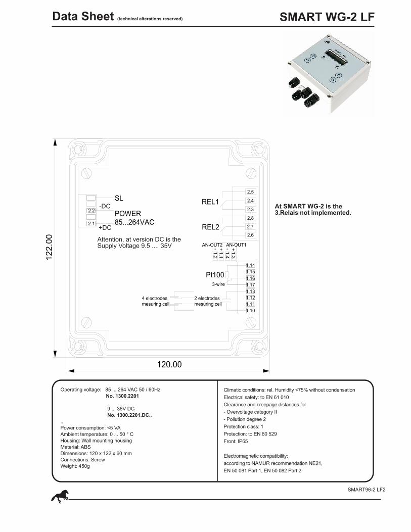
SMART WG-2 LF
1.12
REL2
SL
Pt100
1.10
1.11
POWER85...264VAC
1.13
1.17
1.16
1.15
1.14
4 electrodesmesuring cell
2 electrodesmesuring cell
REL1
1.3
1.4
1.1
1.2
2.7
2.6
2.8
2.3
2.4
2.5
2.1
2.2
+ - + -AN-OUT2 AN-OUT1
3-wire
120.00
12
2.0
0
SMART96-2 LF2
-DC
+DC
At SMART WG-2 is the3.Relais not implemented.
Operating voltage: 85 ... 264 VAC 50 / 60Hz
No. 1300.2201
9 ... 36V DC
No. 1300.2201.DC..
..
Power consumption: <5 VA
Ambient temperature: 0 ... 50 ° C
Housing: Wall mounting housing
Material: ABS
Dimensions: 120 x 122 x 60 mm
Connections: Screw
Weight: 450g
Climatic conditions: rel. Humidity <75% without condensation
Electrical safety: to EN 61 010
Clearance and creepage distances for
- Overvoltage category II
- Pollution degree 2
Protection class: 1
Protection: to EN 60 529
Front: IP65
Electromagnetic compatibility:
according to NAMUR recommendation NE21,
EN 50 081 Part 1, EN 50 082 Part 2
Data Sheet (technical alterations reserved)
Attention, at version DC is theSupply Voltage 9.5 .... 35V
SMART96-2 / WG-2 LF
SMART96-2 LF3
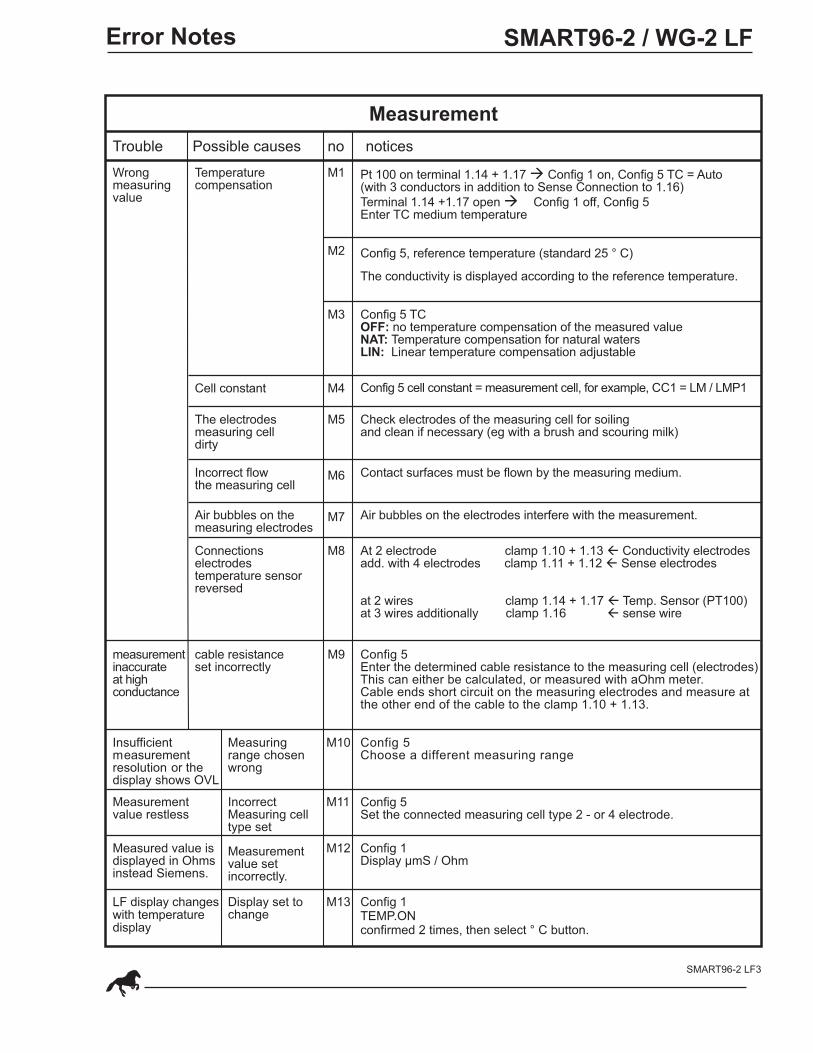
Measurement
Wrongmeasuringvalue
Temperaturecompensation
M1
M4
M5
M6
M7
Error Notes
Trouble Possible causes no notices
Pt 100 on terminal 1.14 + 1.17 à Config 1 on, Config 5 TC = Auto(with 3 conductors in addition to Sense Connection to 1.16)
Terminal 1.14 +1.17 open à Config 1 off, Config 5Enter TC medium temperature
M2 Config 5, reference temperature (standard 25 ° C)
The conductivity is displayed according to the reference temperature.
M3 Config 5 TCOFF: no temperature compensation of the measured valueNAT: Temperature compensation for natural watersLIN: Linear temperature compensation adjustable
Config 5 cell constant = measurement cell, for example, CC1 = LM / LMP1
Check electrodes of the measuring cell for soilingand clean if necessary (eg with a brush and scouring milk)
Contact surfaces must be flown by the measuring medium.
Cell constant
The electrodesmeasuring celldirty
Incorrect flowthe measuring cell
Air bubbles on themeasuring electrodes
Air bubbles on the electrodes interfere with the measurement.
Connectionselectrodestemperature sensorreversed
M8 At 2 electrode clamp 1.10 + 1.13 ß Conductivity electrodesadd. with 4 electrodes clamp 1.11 + 1.12 ß Sense electrodes
at 2 wires clamp 1.14 + 1.17 ß Temp. Sensor (PT100)at 3 wires additionally clamp 1.16 ß sense wire
measurementinaccurateat highconductance
M9
M10
M11
cable resistanceset incorrectly
Config 5Enter the determined cable resistance to the measuring cell (electrodes)This can either be calculated, or measured with aOhm meter.Cable ends short circuit on the measuring electrodes and measure atthe other end of the cable to the clamp 1.10 + 1.13.
Insufficientmeasurementresolution or thedisplay shows OVL
Measuringrange chosenwrong
Config 5Choose a different measuring range
M12
M13
Measurementvalue restless
IncorrectMeasuring celltype set
Config 5Set the connected measuring cell type 2 - or 4 electrode.
Measured value isdisplayed in Ohmsinstead Siemens.
Measurementvalue setincorrectly.
Config 1Display µmS / Ohm
Config 1TEMP.ONconfirmed 2 times, then select ° C button.
LF display changeswith temperaturedisplay
Display set tochange
SMART 96-2 / WG-2 pH/Redox/LF
SMART96-2 LF4
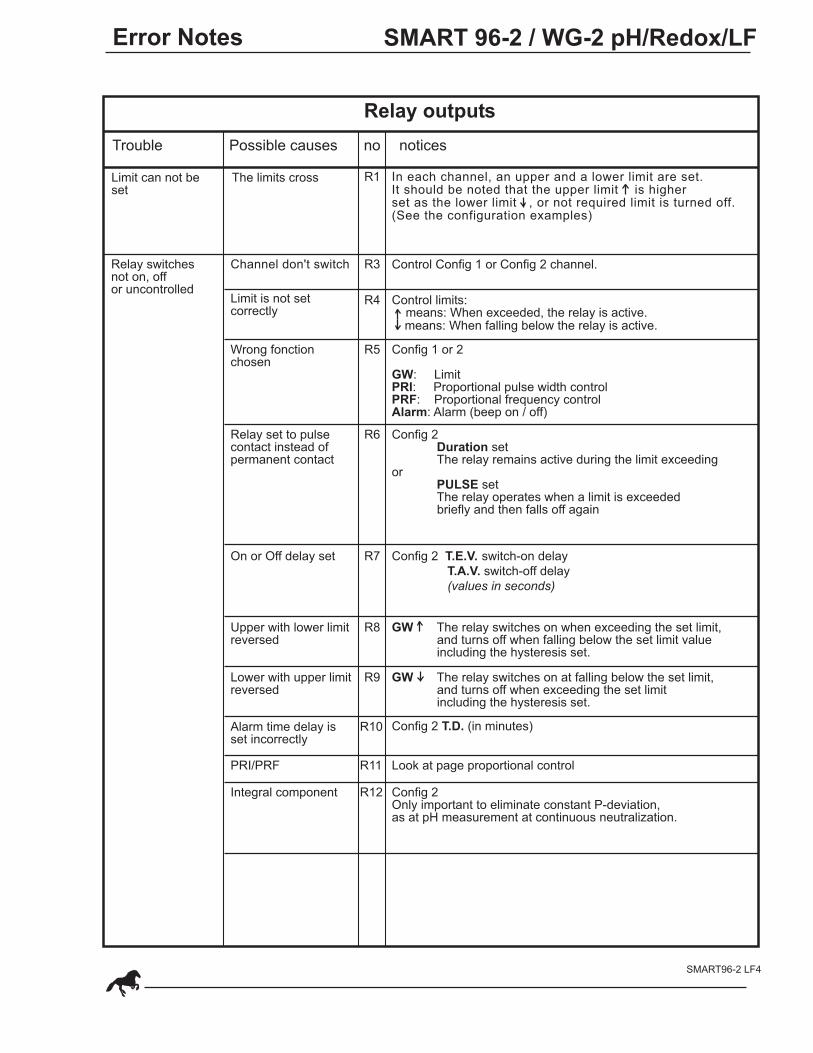
Trouble Possible causes no notices
Relay switchesnot on, offor uncontrolled
Limit can not beset
The limits cross R1
Limit is not setcorrectly
R3
R4
Wrong fonctionchosen
R5 Config 1 or 2
GW: LimitPRI: Proportional pulse width controlPRF: Proportional frequency controlAlarm: Alarm (beep on / off)
Relay set to pulsecontact instead ofpermanent contact
R6 Config 2Duration set The relay remains active during the limit exceeding
orPULSE set
The relay operates when a limit is exceeded briefly and then falls off again
R7
Upper with lower limitreversed
Config 2 T.E.V. switch-on delay
T.A.V. switch-off delay
(values in seconds)
R8
On or Off delay set
GW The relay switches on when exceeding the set limit, and turns off when falling below the set limit value including the hysteresis set.
R9
Alarm time delay isset incorrectly
R10
PRI/PRF R11 Look at page proportional control
Integral component R12 Config 2Only important to eliminate constant P-deviation,as at pH measurement at continuous neutralization.
In each channel, an upper and a lower limit are set.It should be noted that the upper limit is higherset as the lower limit , or not required limit is turned off.(See the configuration examples)
Channel don't switch Control Config 1 or Config 2 channel.
Control limits: means: When exceeded, the relay is active. means: When falling below the relay is active.
Lower with upper limitreversed
GW The relay switches on at falling below the set limit, and turns off when exceeding the set limit including the hysteresis set.
Config 2 T.D. (in minutes)
Relay outputs
Error Notes
0%
0%
7.00 8.00 9.00 10.00
100%
50%
25%
0%
95%
50%
25%
5%
SMART 96-2 / WG-2 pH/Redox/LF
SMART96-2 LF5
Error Notes
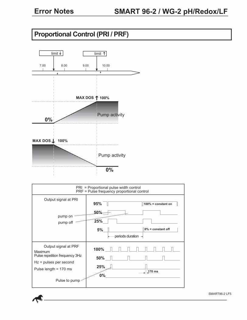
Proportional Control (PRI / PRF)
limit limit
Pump activity
Pump activity
PRI = Proportional pulse width controlPRF = Pulse frequency proportional control
Output signal at PRI
pump on
pump off
Output signal at PRF
MaximumPulse repetition frequency 3Hz
Hz = pulses per second
Pulse length = 170 ms
Pulse to pump
170 ms
periods duration
0% = constant off
100% = constant on
100%
100%
MAX DOS
MAX DOS
Displaymeasurement value
xx.xx E.C.
CONFIG 2
CONFIG 3
CONFIG 4
CONFIG 5
LANGUAGE
TEMPERATURE
DISPLAYµmS
CHANNEL 1RELAIS 1
CHANNEL 2RELAIS 2
CHANNEL 3RELAIS 3
ANALOG 1
ANALOG 2
E.C.0...20 mA 1MAX mA
ONE.C.
ALARM
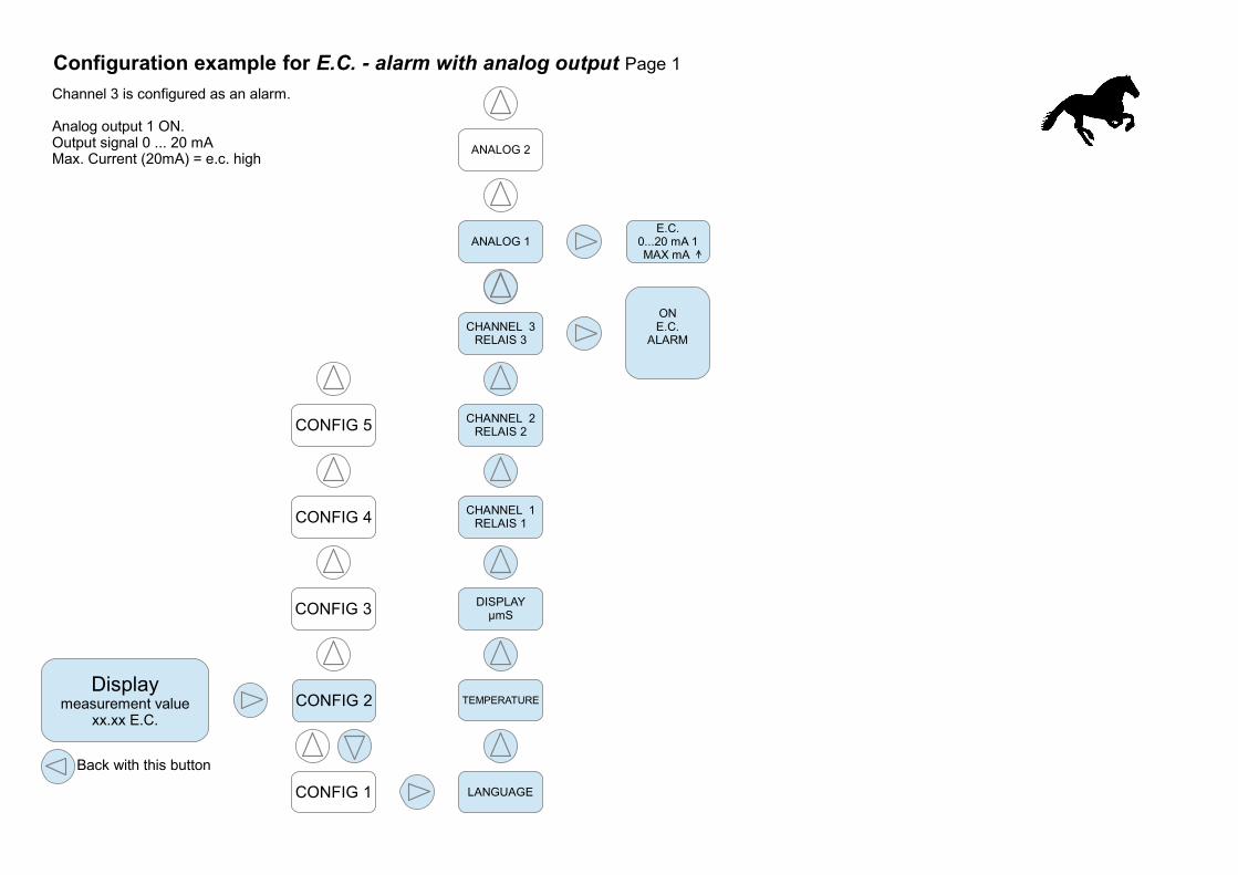
Configuration example for E.C. - alarm with analog output Page 1
Back with this button
Channel 3 is configured as an alarm.
Analog output 1 ON.Output signal 0 ... 20 mAMax. Current (20mA) = e.c. high
CONFIG 1
LIMIT6.50 R3
HYSTERESE
Displaymeasurement value
xx.xx E.C.
CONFIG 1
CONFIG 2
CONFIG 3
CONFIG 4
CONFIG 5
CHANNEL 1
CHANNEL 2
CHANNEL 3
ANALOG 1
ANALOG 2
LIMIT
RELAISDuration / wiper
LIMIT
HYSTERESE
Off delay
On delay
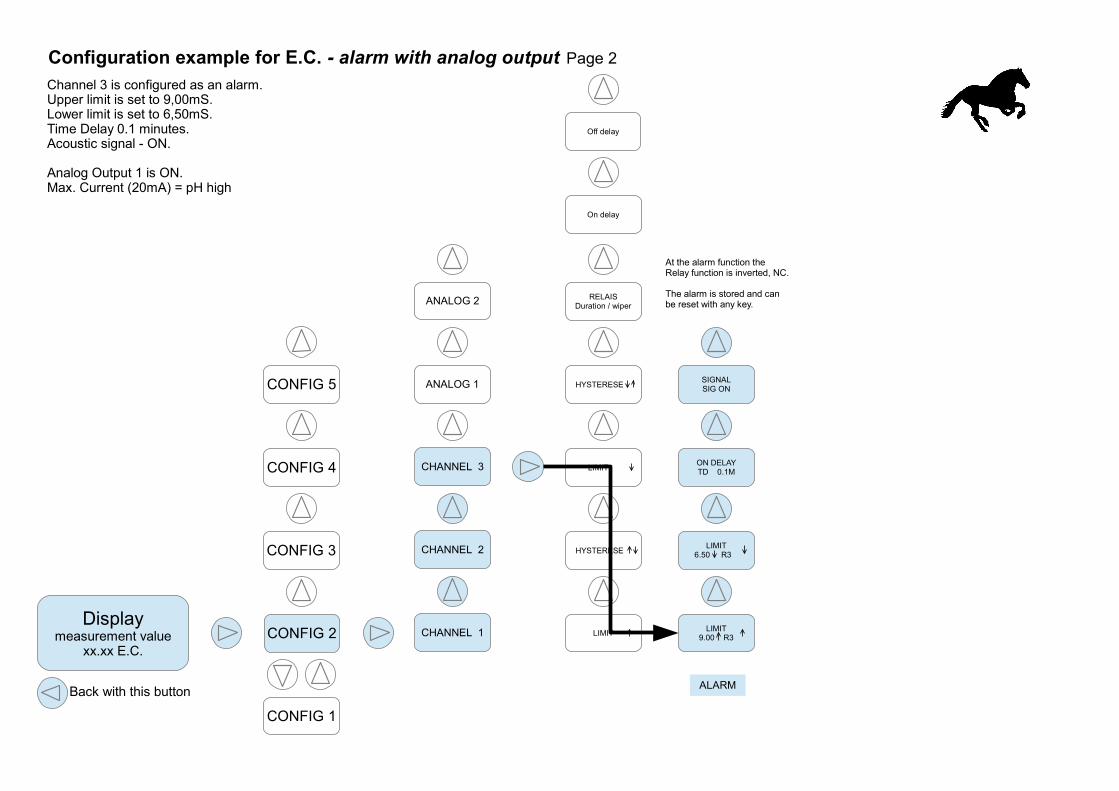
LIMIT9.00 R3
ON DELAYTD 0.1M
SIGNALSIG ON
ALARM
At the alarm function the Relay function is inverted, NC.
The alarm is stored and can be reset with any key.
Configuration example for E.C. - alarm with analog output Page 2
Back with this button
Channel 3 is configured as an alarm.Upper limit is set to 9,00mS.Lower limit is set to 6,50mS.Time Delay 0.1 minutes.Acoustic signal - ON.
Analog Output 1 is ON.Max. Current (20mA) = pH high
Displaymeasurement value
xx.xx E.C.
CONFIG 1
CONFIG 2
CONFIG 3
CONFIG 4
CONFIG 5
CHANNEL 1
CHANNEL 2
CHANNEL 3
ANALOG 1
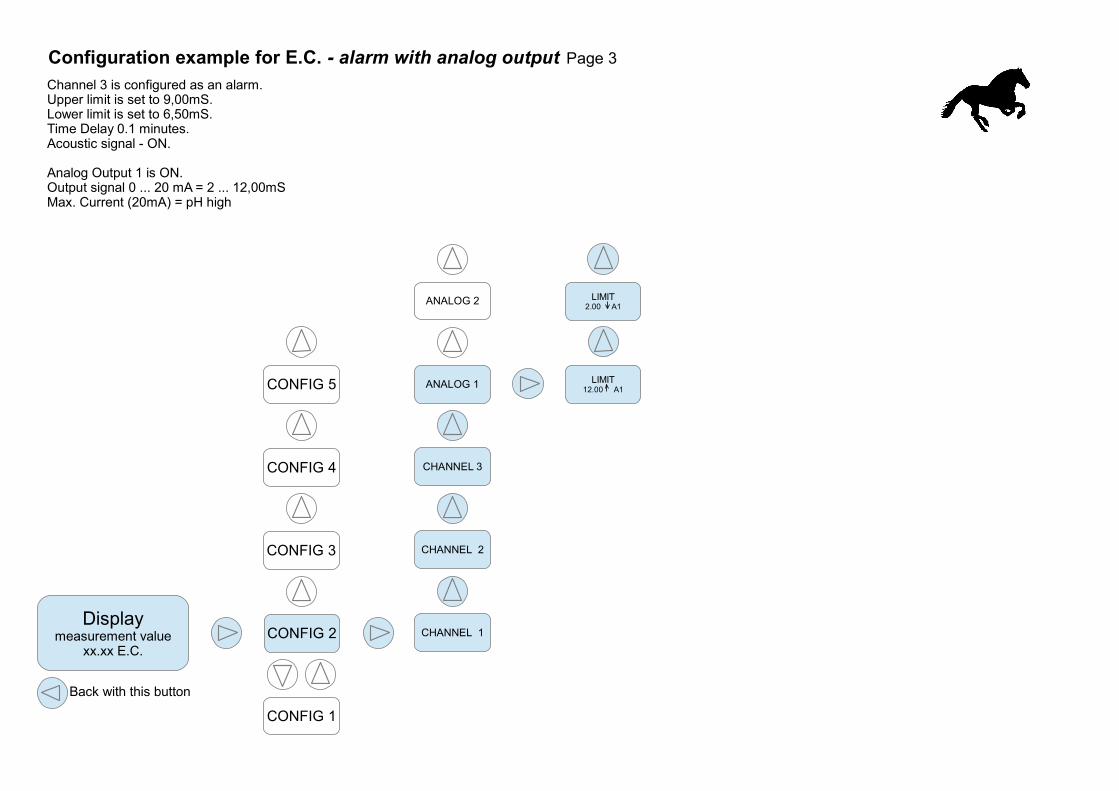
ANALOG 2 LIMIT2.00 A1
LIMIT12.00 A1
Back with this button
Configuration example for E.C. - alarm with analog output Page 3
Channel 3 is configured as an alarm.Upper limit is set to 9,00mS.Lower limit is set to 6,50mS.Time Delay 0.1 minutes.Acoustic signal - ON.
Analog Output 1 is ON.Output signal 0 ... 20 mA = 2 ... 12,00mSMax. Current (20mA) = pH high

ONE.C.
Grenzwert
Displaymeasurement value
xx.xx E.C.
CONFIG 1
CONFIG 2
CONFIG 3
CONFIG 4
CONFIG 5
LANGUAGE
TEMPERATURE
DISPLAYµmS
CHANNEL 1RELAIS 1
CHANNEL 2RELAIS 2
CHANNEL 3RELAIS 3
ANALOG 1
ANALOG 2
Back with this button
Configuration example of a - limit (relay switches at exceeding) Page1
Channel 1 is used as limit switches.Display shows mS
HYSTERESE
HY 0.10
Displaymeasurement value
xx.xx E.C.
CONFIG 1
CONFIG 2
CONFIG 3
CONFIG 4
CONFIG 5
CHANNEL 1
CHANNEL 2
CHANNEL 3
ANALOG 1
ANALOG 2
LIMIT
8.50 R1
RELAISDURATION
LIMIT
AUS R1
HYSTERESE
OFF DELAYTOF 0S
ON DELAYTON 0S
LIMIT-FUNCTION
in Seconds
Back with this button
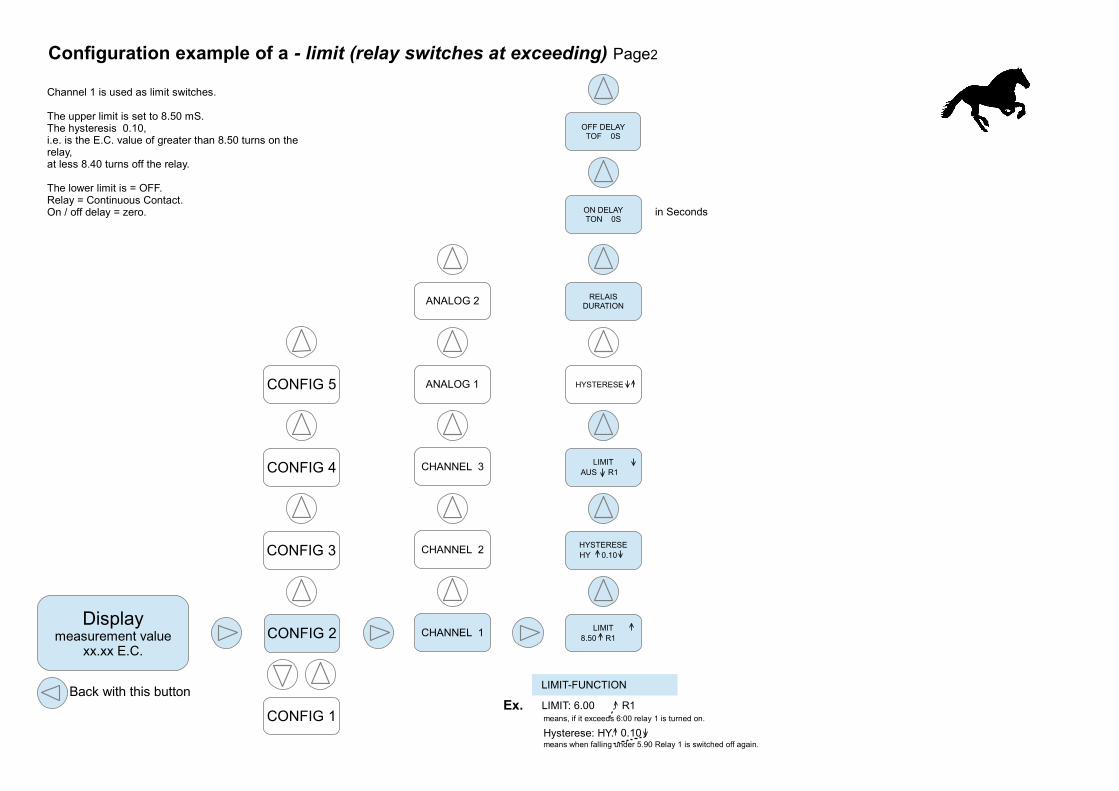
Configuration example of a - limit (relay switches at exceeding) Page2
Channel 1 is used as limit switches.
The upper limit is set to 8.50 mS.The hysteresis 0.10,i.e. is the E.C. value of greater than 8.50 turns on the relay,at less 8.40 turns off the relay.
The lower limit is = OFF.Relay = Continuous Contact.On / off delay = zero.
Ex.
Hysterese: HY.
LIMIT: 6.00 R1
0.10
means, if it exceeds 6:00 relay 1 is turned on.
means when falling under 5.90 Relay 1 is switched off again.
ONE.C.
Grenzwert
Displaymeasurement value
xx.xx E.C.
CONFIG 1
CONFIG 2
CONFIG 3
CONFIG 4
CONFIG 5
LANGUAGE
TEMPERATURE
DISPLAYµmS
CHANNEL 1RELAIS 1
CHANNEL 2RELAIS 2
CHANNEL 3RELAIS 3
ANALOG 1
ANALOG 2
Back with this button
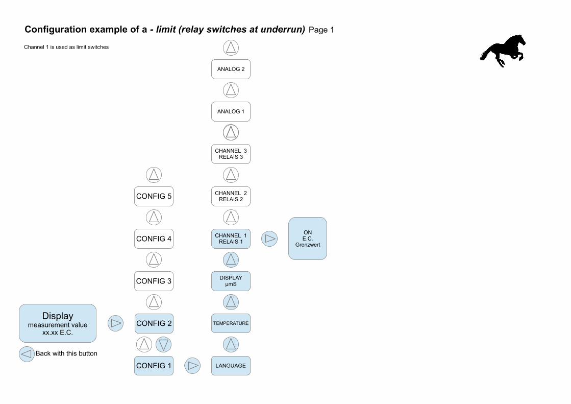
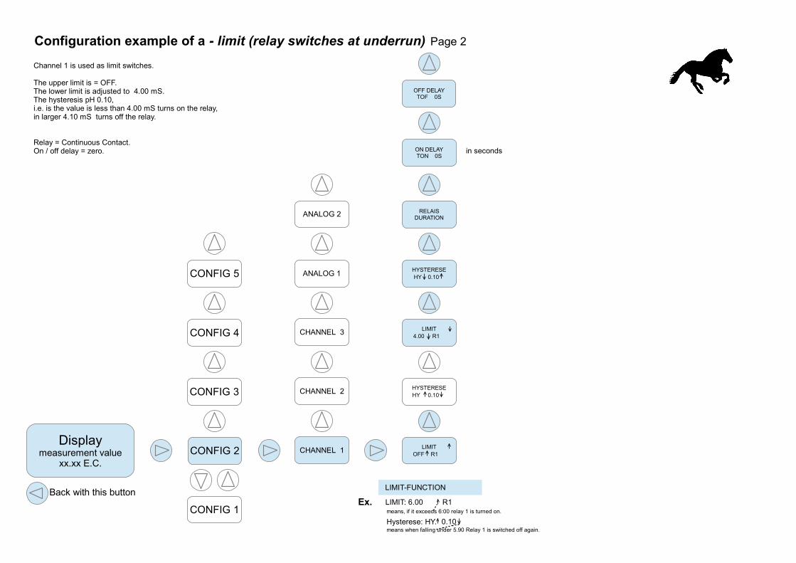
Configuration example of a - limit (relay switches at underrun) Page 1
Channel 1 is used as limit switches
HYSTERESE
HY 0.10
Displaymeasurement value
xx.xx E.C.
CONFIG 1
CONFIG 2
CONFIG 3
CONFIG 4
CONFIG 5
CHANNEL 1
CHANNEL 2
CHANNEL 3
ANALOG 1
ANALOG 2
LIMIT
OFF R1
RELAISDURATION
LIMIT
4.00 R1
HYSTERESE
HY 0.10
OFF DELAYTOF 0S
ON DELAYTON 0S
in seconds
Back with this button
Configuration example of a - limit (relay switches at underrun) Page 2
Channel 1 is used as limit switches.
The upper limit is = OFF.The lower limit is adjusted to 4.00 mS.The hysteresis pH 0.10,i.e. is the value is less than 4.00 mS turns on the relay,in larger 4.10 mS turns off the relay.
Relay = Continuous Contact.On / off delay = zero.
LIMIT-FUNCTION
Ex.
Hysterese: HY.
LIMIT: 6.00 R1
0.10
means, if it exceeds 6:00 relay 1 is turned on.
means when falling under 5.90 Relay 1 is switched off again.
pH 3.0 pH 7.0pH 4.0 pH 5.0 pH 6.0 pH 8.00%
100%
Dosage
LI LI
Pump activity 40%
pH 5.8
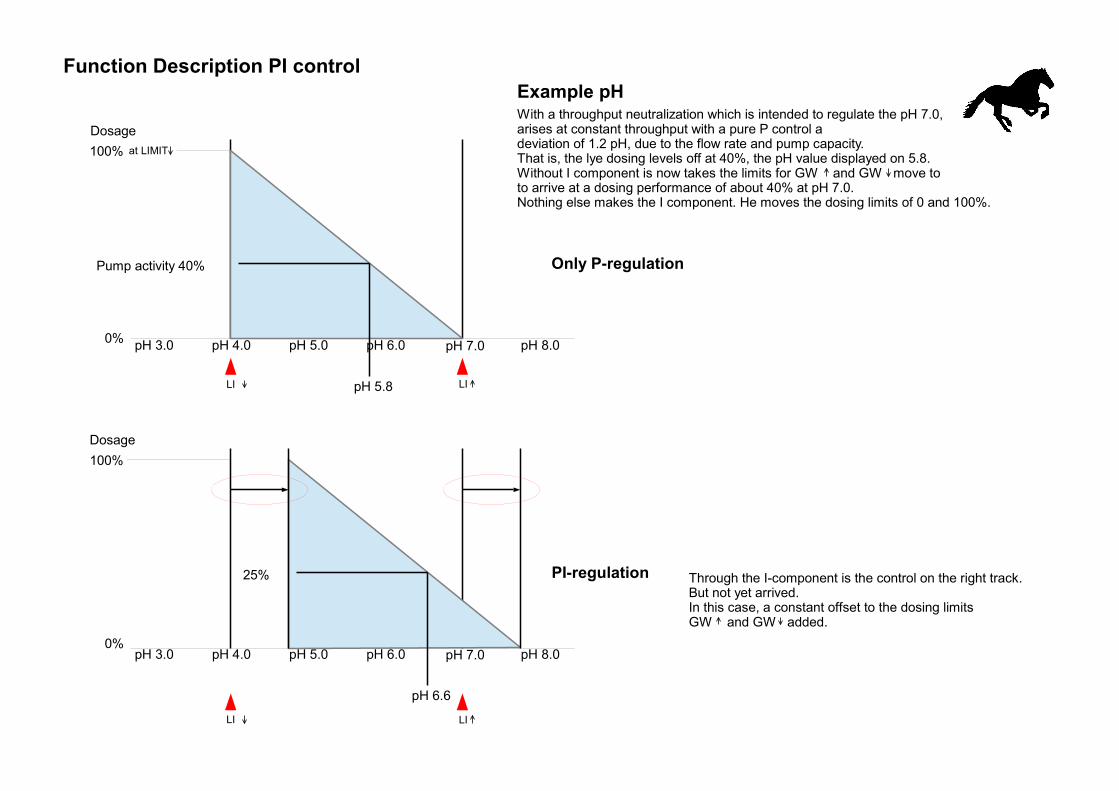
With a throughput neutralization which is intended to regulate the pH 7.0,arises at constant throughput with a pure P control adeviation of 1.2 pH, due to the flow rate and pump capacity.That is, the lye dosing levels off at 40%, the pH value displayed on 5.8.Without I component is now takes the limits for GW and GW move toto arrive at a dosing performance of about 40% at pH 7.0.Nothing else makes the I component. He moves the dosing limits of 0 and 100%.
Only P-regulation
pH 3.0 pH 7.0pH 4.0 pH 5.0 pH 6.0 pH 8.00%
100%
25%
pH 6.6
PI-regulation Through the I-component is the control on the right track.But not yet arrived.In this case, a constant offset to the dosing limitsGW and GW added.
Example pH
Dosage
Function Description PI control
at LIMIT
LI LI
pH 3.0 pH 7.0pH 4.0 pH 5.0 pH 6.0 pH 8.00%
100%
43%
pH 7.1
PI-regulation
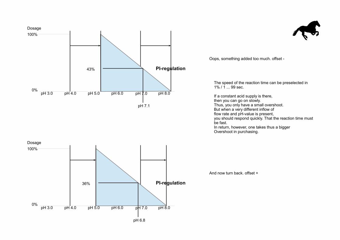
Oops, something added too much. offset -
pH 3.0 pH 7.0pH 4.0 pH 5.0 pH 6.0 pH 8.00%
100%
36%
pH 6.8
PI-regulation
And now turn back. offset +
The speed of the reaction time can be preselected in1% / 1 ... 99 sec.
If a constant acid supply is there,then you can go on slowly.Thus, you only have a small overshoot.But when a very different inflow offlow rate and pH-value is present,you should respond quickly. That the reaction time mustbe fast.In return, however, one takes thus a biggerOvershoot in purchasing.
Dosage
Dosage