Embed Size (px)
Citation preview
© 2003 Apple Computer, Inc. All rights reserved.
Service Source
Apple Studio Display 17" LCD(ADC)
Updated 6 Decenber 2004
© 2003 Apple Computer, Inc. All rights reserved.
Service Source
Take Apart
Apple Studio Display 17" LCD (ADC)

Apple Studio Display 17" LCD Take Apart -
1
General Information
General Information
Overview
Identifying Versions of the Display
There are two versions of the display and although there are no specification differences, in some cases the service part will be different.
The versions can be identified as follows:• Version A has a blue-gray logo (front and back).• Version B has a silver logo (front and back) and a hinge that allows the foot to collapse
to flat.
Note:
Both version A and B have flexible hinges, the difference is that the version B hinge will collapse flat, parallel to the screen, to facilitate packing.
The Launch Button brings up the Apple Display preferences window.Note:
The Power Button turns the display on and off.
Front View Rear View
Launch Button
Power On/Off ButtonUSB Ports
ADC Connector
Apple Studio Display 17" LCD Take Apart -
2
General Information
Tools
The following tools are recommended for the take apart procedures.• Cotton gloves (922-1592)• Hex key set, metric• Phillips #1 screwdriver• Volt meter (for troubleshooting)• Black stick (nylon probe tool 922-5065) or other ESD-safe, non-marring tool• ESD wriststrap and mat
Before Working on the Display
Warning: There is a risk of electric shock, fire or other hazard, if the Inverter Board, ADC Cable, MLB to USB Socket Cable, and the LCD Display Module are not replaced with the correct Apple service part.
Warning: Unless otherwise instructed in the service procedures, to avoid the risk of electric shock, fire or other hazard, disconnect the ADC connector from the computer to ensure that the display is not receiving power during service.
Important:
• The display LCD and the inside and outside of the case can scratch and retain
fingerprints easily.• Use clean soft cotton gloves when working on the display.• Only rest the LCD screen and case parts on a soft clean surface.• If available, place a protective film over the display to protect it from scratches or nicks. • Remove all jewelry that could scratch or damage the display or plastic housing.• Do not press on the LCD display panel or its edges as damage can result. • Do not expose the display to high temperature or humidity.• Do not expose the display to direct sunlight.• Follow ESD safe procedures to avoid circuit damage. Use a grounded wrist strap.

Apple Studio Display 17" LCD Take Apart -
3
General Information
Procedure
FOOT REMOVAL 1. Remove three hex key screws (a). 2. Remove Foot and Hinge Cap.
Screw part number:(a) 922-5551
REAR COVER, EMI SHIELD, BEZEL, AND USB COVER REMOVAL 1. Remove four hex key screws (Rear Cover) (a). 2. Remove Rear Cover and Rear Shield. 3. Remove screw (b). 4. Separate the USB Cover. 5. Peel back Vent Labels if needed to release EMI Shield. 6. Slide the EMI Shield to disengage it from the Chassis, then remove. 7. Remove the Vertical and Horizontal Clips from the Cradle assembly. Note: The Clips can crack or break. Use care when removing. A black stick or flat-blade screwdriver may be helpful. 8. Separate the Bezel assembly from the LCD panel assembly.
Screw part numbers:(a) 922-5965(b) 922-5560
(a)
(a)
EMI Shield
Bezel
(a)
(a)
USB Cover
VentLabels
Cradle
(a)
(b)
Clips
Clips
Apple Studio Display 17" LCD Take Apart -
4
General Information
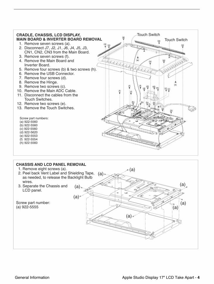
CHASSIS AND LCD PANEL REMOVAL 1. Remove eight screws (a). 2. Peel back Vent Label and Shielding Tape, as needed, to release the Backlight Bulb wires. 3. Separate the Chassis and LCD panel.
Screw part number:(a) 922-5555
(a)
(a)
(a)
(a)(a)
(a)
(a)(a)
CRADLE, CHASSIS, LCD DISPLAY, MAIN BOARD & INVERTER BOARD REMOVAL 1. Remove seven screws (a). 2. Disconnect J7, J2, J1, J6, J4, J5, J3, CN1, CN2, CN3 from the Main Board. 3. Remove seven screws (f). 4. Remove the Main Board and Inverter Board. 5. Remove four screws (b) & two screws (h). 6. Remove the USB Connector. 7. Remove four screws (d). 8. Remove the Hinge. 9. Remove two screws (c). 10. Remove the Main ADC Cable. 11. Disconnect the cables from the Touch Switches. 12. Remove two screws (e). 13. Remove the Touch Switches.
Screw part numbers:(a) 922-5560(b) 922-5560(c) 922-5560(d) 922-5620(e) 922-5553(f) 922-5554(h) 922-5560
Touch SwitchTouch Switch
© 2003 Apple Computer, Inc. All rights reserved.
Service Source
Troubleshooting
Apple Studio Display 17" LCD (ADC)

Apple Studio Display 17" -
1
Symptom Charts
Symptom Charts
How to Use the Symptom Charts
The Symptom Charts included in this chapter will help you diagnose specific symptoms related to the product. Because cures are listed on the charts in the order of most likely solution, try the cures in the order presented. Verify whether or not the product continues to exhibit the symptom. If the symptom persists, try the next cure.
Note:
If you have replaced a module, reinstall the original module before you proceed to the next cure.
Note:
Referring to the Block Diagram in this manual may be helpful.
Blank screen
1. Check ADC cable. Replace cable if damaged.
2. Check for bent pins in the ADC connector (note, it is normal for two of the pins to be slightly longer than the others). If pins are slightly bent, carefully straighten. If pins are severely bent, replace cable. Also, inspect or have the customer inspect the display port on the computer for broken pin dividers. If the display port is damaged it must be repaired before inserting the ADC connector.
3. Plug the display into a known-good computer with a known-good video card and ADC display port. Boot the computer and allow enough time to finish booting.
4. If the power button on the display is flashing, two short flashes then a long flash, in a delayed repeating pattern, this indicates trouble with either the inverter, backlight bulbs or related cables or connectors. With this in mind, continue with the troubleshooting steps to determine the problem.
Apple Studio Display 17" -
2
Symptom Charts
5. To check whether the LCD is working, press the launch button on the display which will bring up the Display Preferences window (if the screen is blank you will not see the window). Shine a bright light such as sunlight or a high intensity lamp (see Important note, below) into the screen and at the same time notice whether you can see a faint image of the Display Preferences window or other desktop items on the screen. • If desktop items can be seen, the LCD panel is working. The problem may be with
the inverter or backlight bulbs or related cables or connectors. Continue with the troubleshooting steps.
• If no desktop items can be seen, the problem may be with the LCD panel or the main board or related cables or connectors.
Important:
Lights get very hot and can quickly damage the display; be extremely careful not to allow too much heat next to the screen or other parts of the display and do not allow the light fixture to touch the screen, or damage can result.
6. Warning: The inverter board generates high voltage when the display is plugged in. Do not touch the inverter board components, pins or connectors, when the display is connected to the computer.
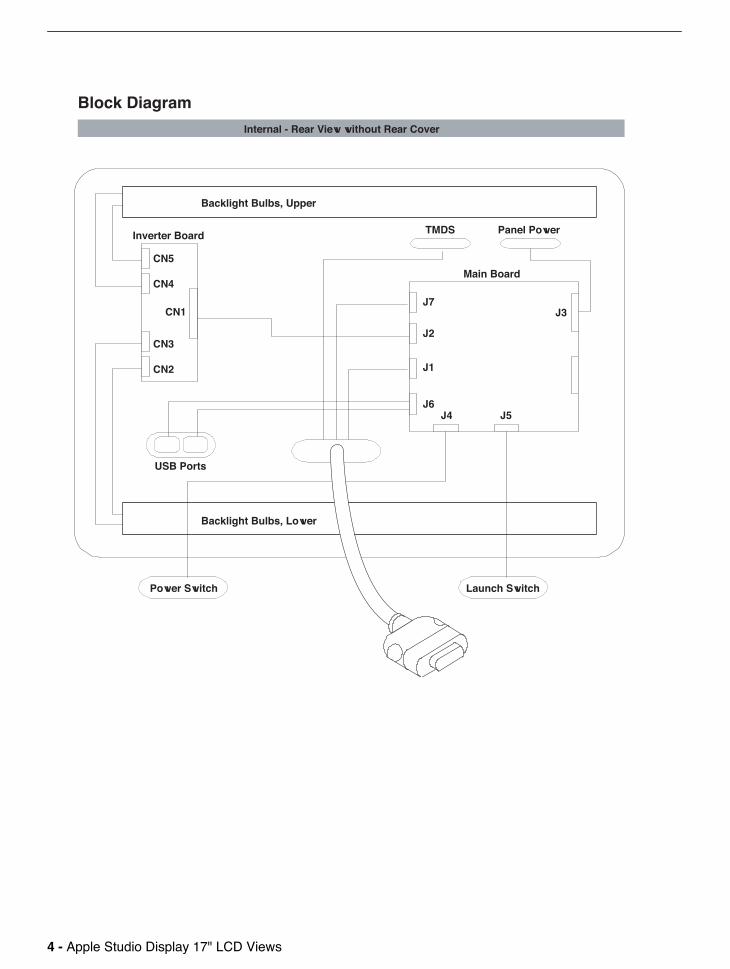
7. Disconnect the display from the computer, then open the display and check for secure connections at TMDS, Panel Power, J7, J2, J1, J3, CN1, CN2, CN3, CN4 and CN5.
Note:
Refer to the Block Diagram in this manual for connector locations.
8. Plug the display into a known-good computer, then boot the computer.
9. Verify +24-28V at input of J7. If not, replace ADC cable.
10. Verify +24-28V at pin 1 of J2. If not, replace the main board.
11. Verify +5V at pin 5 of J3. If not, replace the main board.
Partially dim screen
This symptom indicates a problem with the inverter or backlight bulbs (on the side of the display that is dim), or related cables or connectors. This may be caused by the backlight bulbs or the inverter not working properly.
1. Plug the display into a known-good computer with a known-good video card and ADC display port. Boot the computer.
2. Notice whether the power button on the display is flashing, two short flashes then a long flash, in a delayed repeating pattern. This indicates trouble with either the inverter, backlight bulbs or related cables or connectors (this indicator may not always be exhibited). With this in mind, continue with the troubleshooting steps to determine the problem.
Apple Studio Display 17" -
3
Symptom Charts
3. Warning: The inverter board generates high voltage when the display is plugged in. Do not touch the inverter board components, pins or connectors, when the display is connected to the computer.
Disconnect the display from the computer, then open the display and check for secure connections at CN1, CN2, CN3, CN4 and CN5.
Note:
Refer to the Block Diagram in this manual for connector locations.• If the inverter cable (connected to CN1) is damaged, replace the inverter cable.• If any connectors on the inverter board are damaged, replace the inverter board.• If any of the backlight cables (CN2, CN3, CN4, or CN5) are damaged, replace the
LCD display.
USB device not working
1. Check for bent pins in the ADC connector (note, it is normal for two of the pins to be slightly longer than the others). If pins are slightly bent, carefully straighten. If pins are severely bent, replace cable. Also, inspect or have the customer inspect the display port on the computer for broken pin dividers. If the display port is damaged it must be repaired before inserting the ADC connector.
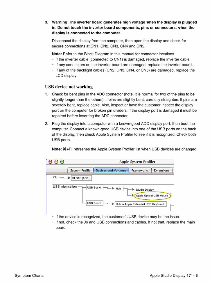
2. Plug the display into a computer with a known-good ADC display port, then boot the computer. Connect a known-good USB device into one of the USB ports on the back of the display, then check Apple System Profiler to see if it is recognized. Check both USB ports.
Note:
x
+R, refreshes the Apple System Profiler list when USB devices are changed.
• If the device is recognized, the customer’s USB device may be the issue.• If not, check the J6 and USB connections and cables. If not that, replace the main
board.
Apple Studio Display 17" -
4
Symptom Charts
Touch switch not working
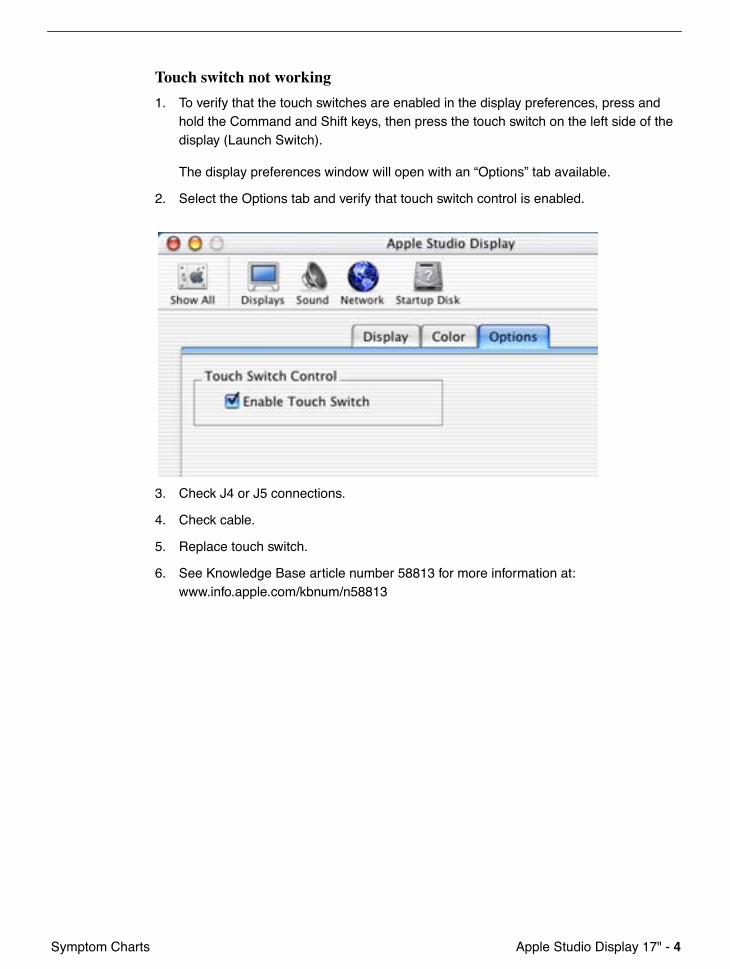
1. To verify that the touch switches are enabled in the display preferences, press and hold the Command and Shift keys, then press the touch switch on the left side of the display (Launch Switch).
The display preferences window will open with an “Options” tab available.
2. Select the Options tab and verify that touch switch control is enabled.
3. Check J4 or J5 connections.
4. Check cable.
5. Replace touch switch.
6. See Knowledge Base article number 58813 for more information at:www.info.apple.com/kbnum/n58813
Apple Studio Display 17" -
5
Symptom Charts
When displaying a single color over the screen area, the LCD panel shows one or more pixels that are not properly lit
Active-matrix LCD technology uses rows and columns of addressable locations (pixels) that render text and images on screen. Each pixel location has three separate subpixels (red, green, and blue) that allow the image to be rendered in full color. Each subpixel has a corresponding transistor responsible for turning the subpixel on or off.
There are typically millions of these subpixels on an LCD display. For example, the LCD panel used in the Apple Cinema HD display is made up of 2.3 million pixels and 6.9 million red, green, and blue subpixels. Occasionally, a transistor does not work perfectly, which may result in the affected subpixel being turned on (bright) or turned off (dark). With the millions of subpixels on a display, it is quite possible to have a low number of faulty transistors on an LCD. Therefore, a certain number of subpixel anomalies is considered acceptable. Rejecting all but perfect LCD panels would significantly increase the retail price for products using LCD displays. These factors apply to all manufacturers using LCD technology—not just Apple products.
To determine whether or not the display has an acceptable number of pixel anomalies, follow the steps below:
1. Set the display image to one of the following colors: all-white display, all-red display, all-green display, or all-blue display.
Note:
Knowledge Base article 112125: Service Diagnostics Matrix, has the LCD Tester Diagnostic Utility that will generate these patterns on the screen.
2. Using a jeweler’s loupe, pocket microscope, or other magnifying device, identify and count each subpixel anomaly:• Bright subpixel anomaly = subpixel that is always on• Dark subpixel anomaly = subpixel that is always off
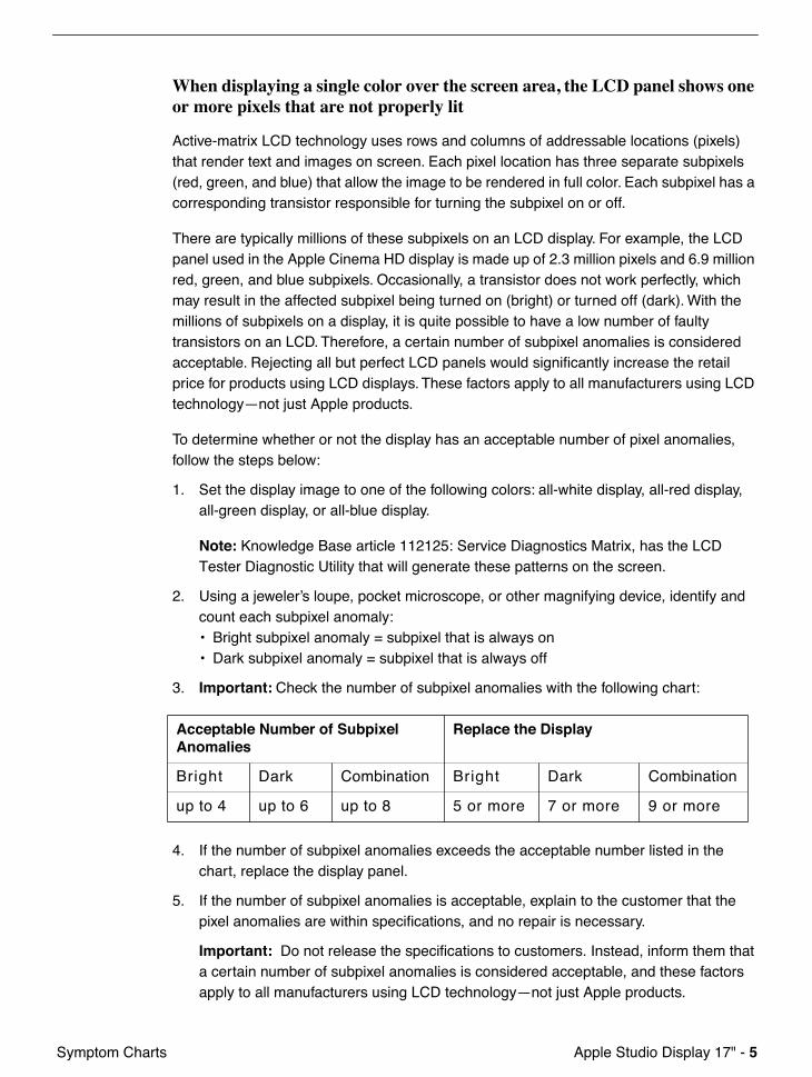
3.
Important:
Check the number of subpixel anomalies with the following chart:
4. If the number of subpixel anomalies exceeds the acceptable number listed in the chart, replace the display panel.
5. If the number of subpixel anomalies is acceptable, explain to the customer that the pixel anomalies are within specifications, and no repair is necessary.
Important:
Do not release the specifications to customers. Instead, inform them that a certain number of subpixel anomalies is considered acceptable, and these factors apply to all manufacturers using LCD technology—not just Apple products.
Acceptable Number of Subpixel Anomalies
Replace the Display
Bright Dark Combination Bright Dark Combination
up to 4 up to 6 up to 8 5 or more 7 or more 9 or more

© 2003 Apple Computer, Inc. All rights reserved.
Service Source
Views
Apple Studio Display 17" LCD (ADC)
Apple Studio Display 17" LCD Views -
1
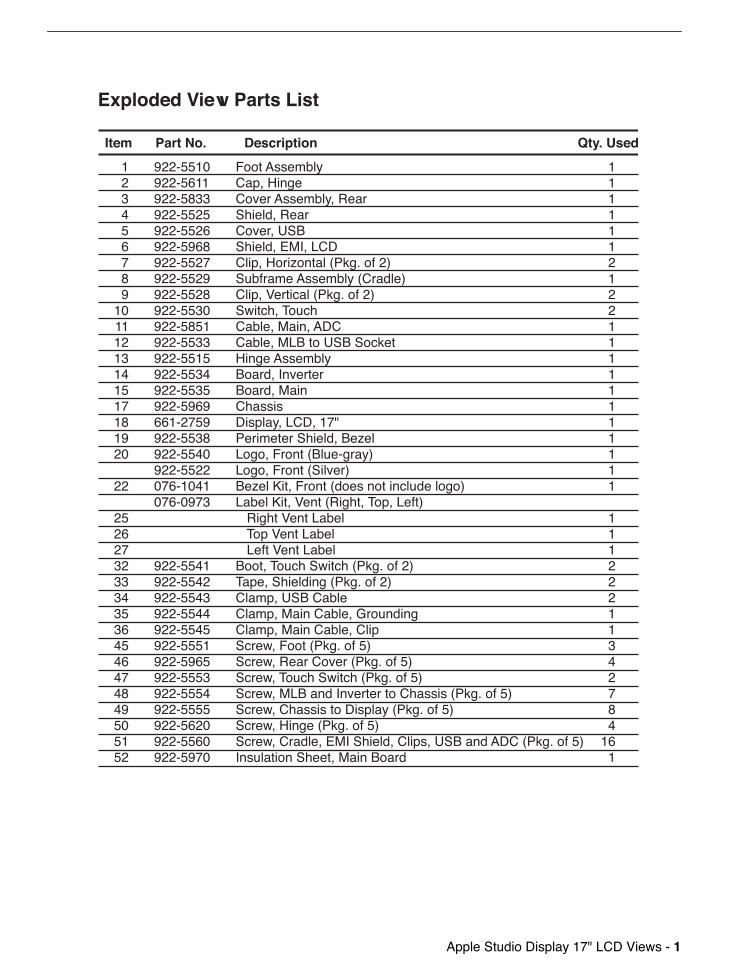
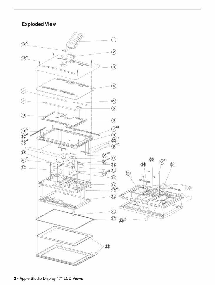
1 922-5510 Foot Assembly 1 2 922-5611 Cap, Hinge 1 3 922-5833 Cover Assembly, Rear 1 4 922-5525 Shield, Rear 1 5 922-5526 Cover, USB 1 6 922-5968 Shield, EMI, LCD 1 7 922-5527 Clip, Horizontal (Pkg. of 2) 2 8 922-5529 Subframe Assembly (Cradle) 1 9 922-5528 Clip, Vertical (Pkg. of 2) 2 10 922-5530 Switch, Touch 2 11 922-5851 Cable, Main, ADC 1 12 922-5533 Cable, MLB to USB Socket 1 13 922-5515 Hinge Assembly 1 14 922-5534 Board, Inverter 1 15 922-5535 Board, Main 1 17 922-5969 Chassis 1 18 661-2759 Display, LCD, 17" 1 19 922-5538 Perimeter Shield, Bezel 1 20 922-5540 Logo, Front (Blue-gray) 1 922-5522 Logo, Front (Silver) 1 22 076-1041 Bezel Kit, Front (does not include logo) 1 076-0973 Label Kit, Vent (Right, Top, Left) 25 Right Vent Label 1 26 Top Vent Label 1 27 Left Vent Label 1 32 922-5541 Boot, Touch Switch (Pkg. of 2) 2 33 922-5542 Tape, Shielding (Pkg. of 2) 2 34 922-5543 Clamp, USB Cable 2 35 922-5544 Clamp, Main Cable, Grounding 1 36 922-5545 Clamp, Main Cable, Clip 1 45 922-5551 Screw, Foot (Pkg. of 5) 3 46 922-5965 Screw, Rear Cover (Pkg. of 5) 4 47 922-5553 Screw, Touch Switch (Pkg. of 5) 2 48 922-5554 Screw, MLB and Inverter to Chassis (Pkg. of 5) 7 49 922-5555 Screw, Chassis to Display (Pkg. of 5) 8 50 922-5620 Screw, Hinge (Pkg. of 5) 4 51 922-5560 Screw, Cradle, EMI Shield, Clips, USB and ADC (Pkg. of 5) 16 52 922-5970 Insulation Sheet, Main Board 1
Item Part No. Description Qty. Used
Exploded View Parts List
2 -
Apple Studio Display 17" LCD Views
22
�����
���
45x3
46x4
25
26
51
51x7
10x2
47x2
15
52
48x4
19
20
18
49x8
33x2
35
3436
51x4
34
17
14
13
12
11
32x2
9x2
8
7x2
6
5
27
4
3
2
1
48x3
51x2
51x2
50x4
Exploded View

Apple Studio Display 17" LCD Views -
3
Cable, MLB to LCD922-5550
Main Board922-5535
Inverter Board922-5534
Cable Assembly,Launch Switch922-5546
Clamp, USB Cable922-5543
Clamp, Main Cable, Clip
922-5545
Clamp, Main Cable, Grounding922-5544
Cable, MLB to USB Socket922-5533
Cable Assembly,Power Switch922-5547
Cable, Main, ADC922-5851
Touch Switch922-5530
Touch Switch922-5530
Cable, MLB to Inverter
922-5549
Wiring Diagram
4 -
Apple Studio Display 17" LCD Views
TMDS Panel Power
J7
CN5
CN4
CN3
CN1
CN2
USB Ports
Internal - Rear View without Rear Cover
Inverter Board
Main Board
J2
J1
J6J4 J5
J3
Block Diagram
Backlight Bulbs, Lower
Power Switch Launch Switch
Backlight Bulbs, Upper


![From Technologies to Market · • ComparisonsWith LCD and OLED ... (Apple,Samsung,LG,BOE,Mikro Mesa,Playnitride,ITRI…) ... [1] research 2](https://img.pdfslide.us/doc/110x75/5cabcd8988c993bf748d9863/from-technologies-to-market-comparisonswith-lcd-and-oled-applesamsunglgboemikro.jpg)