Embed Size (px)
Citation preview

Studies about the Low Voltage Ride ThroughCapabilities of Variable-Speed Motor-Generators of
Pumped Storage Hydro Power Plants
Erich Schmidt, Member, IEEE, Johann Ertl, Member, IEEE,
Alexander Preiss, Roman Zensch, Robert Schurhuber, Johann Hell
Abstract – In order to fulfil the new challenges
within power grids arising from an increasing uti-
lization of renewable energy resources, there is an
upcoming demand for pumped storage hydro power
plants. Thereby, a full flexibility of active and reac-
tive power production in generating mode as well
as power consumption in pumping mode in con-
junction with the best available efficiency of both
electric and hydraulic devices gains in significance.
Nowadays, the utilization of variable-speed pump-
turbine units with either synchronous or doubly-fed
asynchronous motor-generators can be applied for
these tasks. Since these variable-speed units have
a very different behaviour in comparison to fixed-
speed synchronous machines, more detailed analy-
ses should to be carried out in the design phase of
such units. In order to achieve accurate data about
steady-state as well as transient behaviour, simu-
lation models of both mentioned arrangements are
developed.
Keywords – Power generation, Grid code, Syn-
chronous machine, Asynchronous machine, Doubly-
fed induction machine
I. Introduction
A central part of transmission system operators re-sponsibility is to ensure system security with a highlevel of reliability and quality [1]. The system be-haviour in disturbed operating conditions dependsupon the response of power generating facilities to de-viations from nominal values of voltage and frequency.With a growing utilization of power generation unitsfed by renewable energy resources additionally to ex-isting power generation units, general requirementsfor all power generation units have to be defined inmore detail. These specifications defined in so calledGrid Codes cover both fixed-speed and variable-speedpower generators. In order to fully comply with thosenew regulations, there are novel challenges regardingcapabilities and performances in particular for motor-generator units of hydro-electric power plants.
Erich Schmidt, Johann Ertl are with the Institute of EnergySystems and Electric Drives, Vienna University of Technology,Vienna, Austria.
Alexander Preiss, Roman Zensch, Robert Schurhuber, Jo-hann Hell are with Andritz Hydro Ltd., Vienna, Austria.
In hydro-electric power plants, pump-turbines areoptimized for operating points defined by speed, headand discharge [2]. At fixed-speed operation, only lim-ited deviations of these operating conditions are al-lowed. On the other hand at variable-speed opera-tion, the allowable variation of these operating condi-tions is enlarged. Consequently, such variable-speedpump-turbine units offer greater flexibility and higherefficiency in both operating modes [2]–[4].
For such variable-speed pump-turbine units, thereexist two main types of motor-generator units, thesynchronous machine with either an electrical or a per-manent magnet excitation and the doubly-fed asyn-chronous induction machine [2]–[6]. Both types ofmotor-generators as depicted in Fig. 1 and Fig. 2 offerseveral advantages with generating as well as pumpingmode [6]:
• Increased efficiency and extended operation rangein both generating and pumping modes.
• Optimized adaptation to the hydraulic systemin particular with partial-load and pump-turbineoperation.
• Possibility of active power control in pumpingmode.
• Possibility of an active injection of reactive power.
• Improved network stability due to separated con-trol of active and reactive power.
• Increased dynamic performance for operating sta-bility purposes.
Due to the variable-speed operation mode, both typesof motor-generators have to be equipped with powerelectronic rectifier units, too. Nowadays, back-to-back voltage source inverters (VSI) with pulse widthmodulation (PWM) are utilized, depending on thepower range with two- or three-level arrangements us-ing IGBT or IGCT modules [3]–[7].
With regard to the above mentioned view points,the paper presents both arrangements of motor-generators and in particular modelling of the utilizedthree-level PWM converters in order to represent theswitching behaviour of the two back-to-back connectedparts. The main focus of the simulations carried out
Grid Transformer
AC
DC
DC
AC
Voltage Source Inverter
SM
Motor-Generator
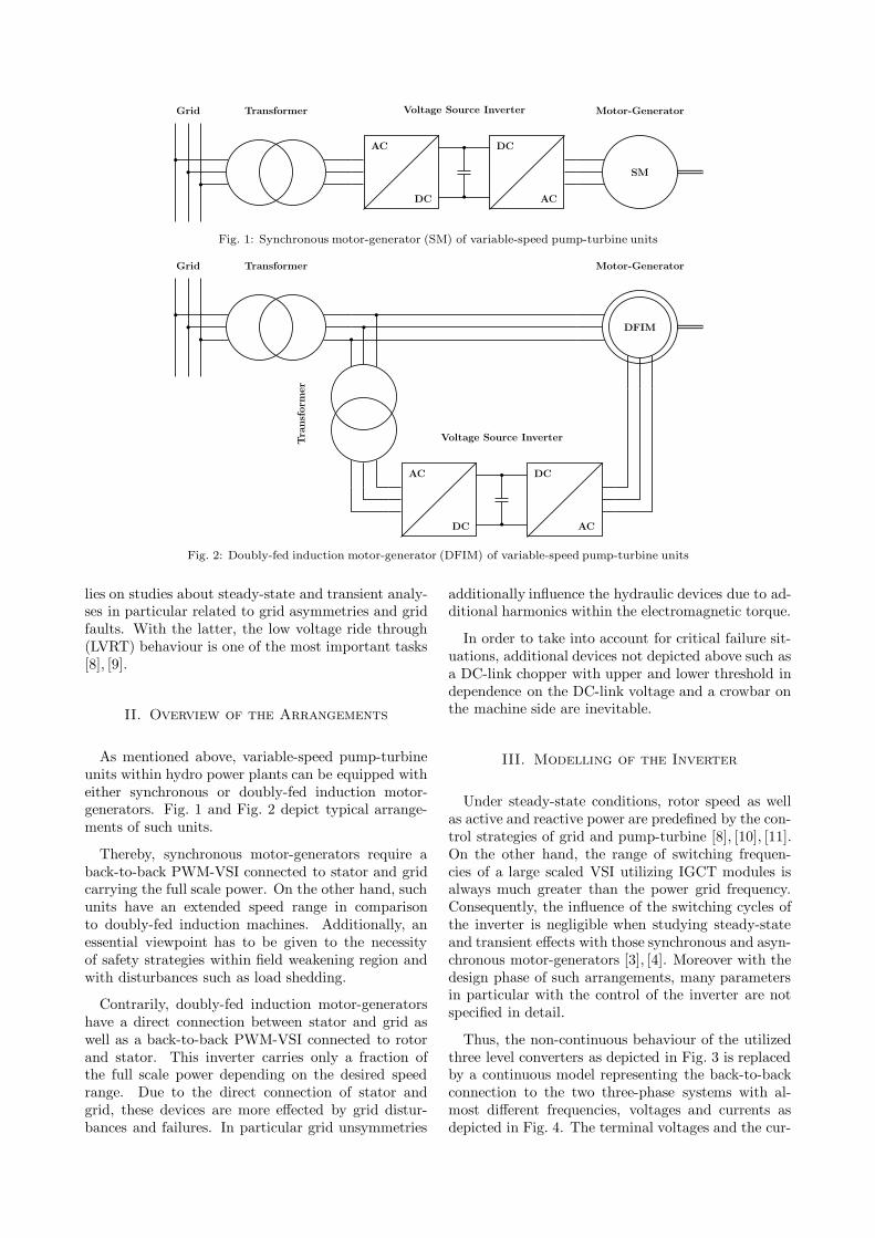
Fig. 1: Synchronous motor-generator (SM) of variable-speed pump-turbine units
Grid Transformer
DFIM
Motor-Generator
AC
DC
DC
AC
Voltage Source InverterTra
nsf
orm
er
Fig. 2: Doubly-fed induction motor-generator (DFIM) of variable-speed pump-turbine units
lies on studies about steady-state and transient analy-ses in particular related to grid asymmetries and gridfaults. With the latter, the low voltage ride through(LVRT) behaviour is one of the most important tasks[8], [9].
II. Overview of the Arrangements
As mentioned above, variable-speed pump-turbineunits within hydro power plants can be equipped witheither synchronous or doubly-fed induction motor-generators. Fig. 1 and Fig. 2 depict typical arrange-ments of such units.
Thereby, synchronous motor-generators require aback-to-back PWM-VSI connected to stator and gridcarrying the full scale power. On the other hand, suchunits have an extended speed range in comparisonto doubly-fed induction machines. Additionally, anessential viewpoint has to be given to the necessityof safety strategies within field weakening region andwith disturbances such as load shedding.
Contrarily, doubly-fed induction motor-generatorshave a direct connection between stator and grid aswell as a back-to-back PWM-VSI connected to rotorand stator. This inverter carries only a fraction ofthe full scale power depending on the desired speedrange. Due to the direct connection of stator andgrid, these devices are more effected by grid distur-bances and failures. In particular grid unsymmetries
additionally influence the hydraulic devices due to ad-ditional harmonics within the electromagnetic torque.
In order to take into account for critical failure sit-uations, additional devices not depicted above such asa DC-link chopper with upper and lower threshold independence on the DC-link voltage and a crowbar onthe machine side are inevitable.
III. Modelling of the Inverter
Under steady-state conditions, rotor speed as wellas active and reactive power are predefined by the con-trol strategies of grid and pump-turbine [8], [10], [11].On the other hand, the range of switching frequen-cies of a large scaled VSI utilizing IGCT modules isalways much greater than the power grid frequency.Consequently, the influence of the switching cycles ofthe inverter is negligible when studying steady-stateand transient effects with those synchronous and asyn-chronous motor-generators [3], [4]. Moreover with thedesign phase of such arrangements, many parametersin particular with the control of the inverter are notspecified in detail.
Thus, the non-continuous behaviour of the utilizedthree level converters as depicted in Fig. 3 is replacedby a continuous model representing the back-to-backconnection to the two three-phase systems with al-most different frequencies, voltages and currents asdepicted in Fig. 4. The terminal voltages and the cur-
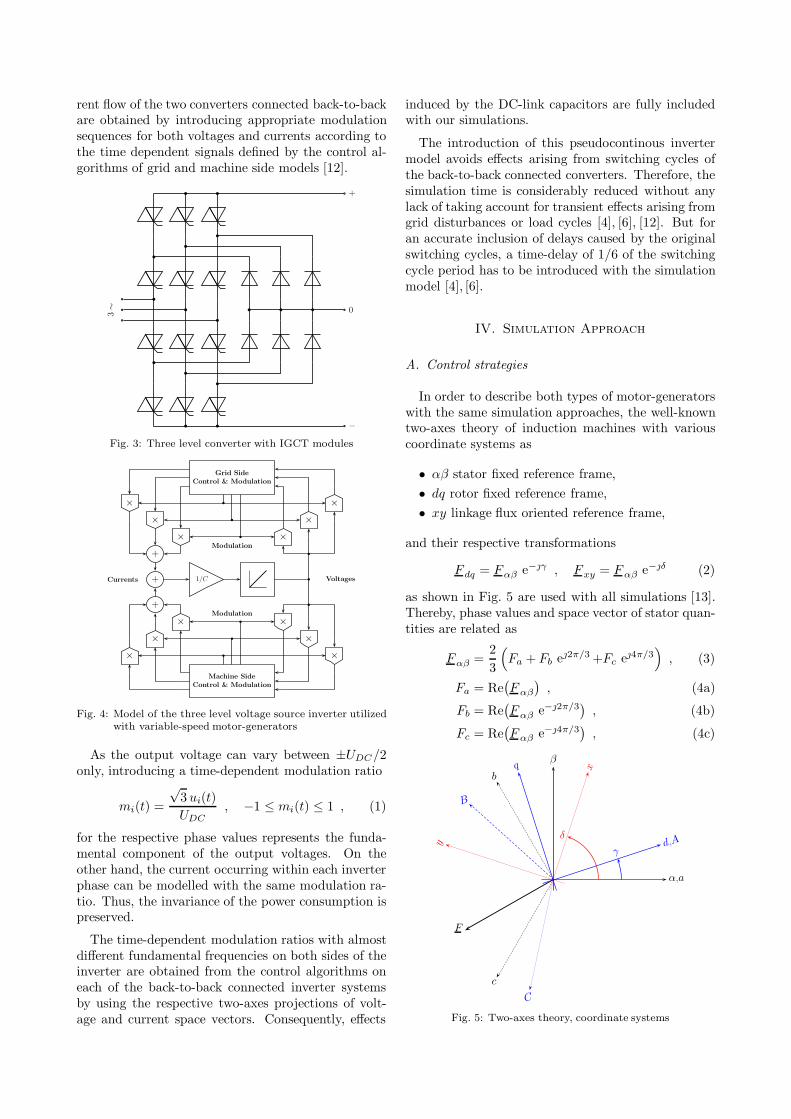
rent flow of the two converters connected back-to-backare obtained by introducing appropriate modulationsequences for both voltages and currents according tothe time dependent signals defined by the control al-gorithms of grid and machine side models [12].
3∼ 0
+
−
Fig. 3: Three level converter with IGCT modules
+Currents 1/C Voltages
×
×
×
+
×
×
×
Modulation
Grid Side
Control & Modulation
×
×
×
+
×
×
×Modulation
Machine Side
Control & Modulation
Fig. 4: Model of the three level voltage source inverter utilizedwith variable-speed motor-generators
As the output voltage can vary between ±UDC/2only, introducing a time-dependent modulation ratio
mi(t) =
√3 ui(t)
UDC, −1 ≤ mi(t) ≤ 1 , (1)
for the respective phase values represents the funda-mental component of the output voltages. On theother hand, the current occurring within each inverterphase can be modelled with the same modulation ra-tio. Thus, the invariance of the power consumption ispreserved.
The time-dependent modulation ratios with almostdifferent fundamental frequencies on both sides of theinverter are obtained from the control algorithms oneach of the back-to-back connected inverter systemsby using the respective two-axes projections of volt-age and current space vectors. Consequently, effects
induced by the DC-link capacitors are fully includedwith our simulations.
The introduction of this pseudocontinous invertermodel avoids effects arising from switching cycles ofthe back-to-back connected converters. Therefore, thesimulation time is considerably reduced without anylack of taking account for transient effects arising fromgrid disturbances or load cycles [4], [6], [12]. But foran accurate inclusion of delays caused by the originalswitching cycles, a time-delay of 1/6 of the switchingcycle period has to be introduced with the simulationmodel [4], [6].
IV. Simulation Approach
A. Control strategies
In order to describe both types of motor-generatorswith the same simulation approaches, the well-knowntwo-axes theory of induction machines with variouscoordinate systems as
• αβ stator fixed reference frame,
• dq rotor fixed reference frame,
• xy linkage flux oriented reference frame,
and their respective transformations
F dq = Fαβ e−γ , Fxy = F αβ e−δ (2)
as shown in Fig. 5 are used with all simulations [13].Thereby, phase values and space vector of stator quan-tities are related as
Fαβ =2
3
(
Fa + Fb e2π/3 +Fc e4π/3
)
, (3)
Fa = Re(
F αβ
)
, (4a)
Fb = Re(
F αβ e−2π/3)
, (4b)
Fc = Re(
F αβ e−4π/3)
, (4c)
F
α,a
β
b
c
d,A
q
B
C
x
y
γ
δ
Fig. 5: Two-axes theory, coordinate systems

as well as phase values and space vector of rotor quan-tities
F dq =2
3
(
FA + FB e2π/3 +FC e4π/3
)
, (5)
FA = Re(
F dq
)
, (6a)
FB = Re(
F dq e−2π/3)
, (6b)
FC = Re(
F dq e−4π/3)
, (6c)
respectively.
Active power of the stator
P (t) =3
2Re
(
I∗αβ Uαβ
)
=3
2
(
Iα Uα + Iβ Uβ
)
(7a)
=3
2Re
(
I∗dq Udq
)
=3
2
(
Id Ud + Iq Uq
)
(7b)
=3
2Re
(
I∗xy Uxy
)
=3
2
(
Ix Ux + Iy Uy
)
(7c)
and reactive power of the stator
Q(t) =3
2Im
(
I∗
αβ Uαβ
)
=3
2
(
Iα Uβ − Iβ Uα
)
(8a)
=3
2Im
(
I∗
dq Udq
)
=3
2
(
Id Uq − Iq Ud
)
(8b)
=3
2Im
(
I∗
xy Uxy
)
=3
2
(
Ix Uy − Iy Ux
)
(8c)
will describe power flow with both types of motor-generators. Based on the introduced reference frames,both power components are independently describedby respective voltage and current space vectors.
Following the suggestions with [14], [15], the syn-chronous machine will be modelled within the dq ro-tor fixed reference frame while the doubly-fed asyn-chronous machine will be modelled within the xy ref-erence frame adjusted to a vanishing x-component ofthe stator voltage. The latter approach significantlysimplifies the cross-coupling of the components of sta-tor and rotor currents with the control algorithm.
B. Low voltage ride through cycles
Detailed investigations of LVRT behaviour and ca-pabilities according to various grid code requirementsare carried out in detail. Fig. 6 depicts typical lowvoltage ride through cycles as defined by various GridCodes. In order to comply with this requirements, afast acting voltage control has to provide typically areactive current in dependence on the voltage drop asdepicted in Fig. 7. Thereby, the active power range isreduced according to pre-defined current limits.
According to the LVRT-B cycle depicted above, thebehaviour of both a permanent magnet synchronous(PMSM) and a doubly-fed induction machine (DFIM)are shown in the following.
Fig. 8, Fig. 9 and Fig. 10, Fig. 11 show active andreactive powers as well as voltages and currents within
t/(ms)
U/U0
0 400 800 1200
0.15
0.50
0.70
1.00
(A) (B) (C)
Fig. 6: Typical low voltage ride through cycles
∆U/U0
∆Ix/I0
-0.5
+0.5
-0.05
+0.05
-1
+1
Fig. 7: Typical reactive current support during grid faults
the dq reference frame obtained with a PMSM with anapparent power of 35 MVA, respectively.
On the other hand, Fig. 12, Fig. 13, Fig. 14 showactive and reactive powers obtained with a DFIM with
0.5 0.6 0.7 0.8 0.9 1.0 1.1 1.2 1.3 1.4 1.5−1.50
−1.25
−1.00
−0.75
−0.50
−0.25
0.00
0.25
0.50
0.75
1.00
1.25
1.50
Time/s
p
g
qg
Fig. 8: Active and reactive power during a LVRT-B cycleon the grid side, PMSM
0.5 0.6 0.7 0.8 0.9 1.0 1.1 1.2 1.3 1.4 1.5−1.50
−1.25
−1.00
−0.75
−0.50
−0.25
0.00
0.25
0.50
0.75
1.00
1.25
1.50
Time/s
p
s
qs
Fig. 9: Active and reactive power during a LVRT-B cycleon the machine side, PMSM

0.5 0.6 0.7 0.8 0.9 1.0 1.1 1.2 1.3 1.4 1.5−1.50
−1.25
−1.00
−0.75
−0.50
−0.25
0.00
0.25
0.50
0.75
1.00
1.25
1.50
Time/s
ug
ig
igx
igy
udc
Fig. 10: Voltages and currents during a LVRT-B cycle onthe grid side, PMSM
0.5 0.6 0.7 0.8 0.9 1.0 1.1 1.2 1.3 1.4 1.5−1.50
−1.25
−1.00
−0.75
−0.50
−0.25
0.00
0.25
0.50
0.75
1.00
1.25
1.50
Time/s
us
is
isd
isq
Fig. 11: Voltages and currents during a LVRT-B cycle onthe machine side, PMSM
an apparent power of 350 MVA. Accordingly, Fig. 15,Fig. 16, Fig. 17 show voltages and currents within thexy reference frame.
Obviously, both arrangements can fulfil the require-ments of the Grid Code successfully. Thereby, theLVRT operational behaviour of the PMSM is coveredmainly by the converter while the machine operatesregularly. On the other hand, there are very high cur-rent peaks with the DFIM which can only be compen-sated by using the crowbar. Consequently, the LVRToperational behaviour now shows rather slowly de-creasing oscillations according to very long time con-stants of the machine in the range of (6 . . .8) s.
V. Conclusion
The utilization of variable-speed pump-turbineunits such as synchronous or doubly-fed inductionmotor-generators with hydro power plants allows fornew challenges within the electric energy markets. Anapplication of these units in the range from 30 MVA up
0.5 0.6 0.7 0.8 0.9 1.0 1.1 1.2 1.3 1.4 1.5 1.6 1.7 1.8 1.9 2.0−2.50
−2.00
−1.50
−1.00
−0.50
0.00
0.50
1.00
1.50
2.00
2.50
Time/s
p
g
qg
Fig. 12: Active and reactive power during a LVRT-B cycleon the grid side, DFIM
0.5 0.6 0.7 0.8 0.9 1.0 1.1 1.2 1.3 1.4 1.5 1.6 1.7 1.8 1.9 2.0−2.50
−2.00
−1.50
−1.00
−0.50
0.00
0.50
1.00
1.50
2.00
2.50
Time/s
p
s
qs
Fig. 13: Active and reactive power during a LVRT-B cycleon the stator side, DFIM
0.5 0.6 0.7 0.8 0.9 1.0 1.1 1.2 1.3 1.4 1.5 1.6 1.7 1.8 1.9 2.0−2.50
−2.00
−1.50
−1.00
−0.50
0.00
0.50
1.00
1.50
2.00
2.50
Time/s
p
r
qr
Fig. 14: Active and reactive power during a LVRT-B cycleon the rotor side, DFIM
to 500 MVA requires powerful design and simulationmethods in order to reliably predict both steady-stateas well as transient operational behaviour. In addi-tion to the above presented results, advantages anddrawbacks of both types of motor-generators as well as

0.5 0.6 0.7 0.8 0.9 1.0 1.1 1.2 1.3 1.4 1.5 1.6 1.7 1.8 1.9 2.0−2.50
−2.00
−1.50
−1.00
−0.50
0.00
0.50
1.00
1.50
2.00
2.50
Time/s
ug
ig
igx
igy
udc
Fig. 15: Voltages and currents during a LVRT-B cycle onthe grid side, DFIM
0.5 0.6 0.7 0.8 0.9 1.0 1.1 1.2 1.3 1.4 1.5 1.6 1.7 1.8 1.9 2.0−2.50
−2.00
−1.50
−1.00
−0.50
0.00
0.50
1.00
1.50
2.00
2.50
Time/s
us
is
isx
isy
Fig. 16: Voltages and currents during a LVRT-B cycle onthe stator side, DFIM
0.5 0.6 0.7 0.8 0.9 1.0 1.1 1.2 1.3 1.4 1.5 1.6 1.7 1.8 1.9 2.0−2.50
−2.00
−1.50
−1.00
−0.50
0.00
0.50
1.00
1.50
2.00
2.50
Time/s
ur
ir
irx
iry
Fig. 17: Voltages and currents during a LVRT-B cycle onthe rotor side, DFIM
the influence of various control strategies are very im-portant tasks which are further analyzed. Moreover,detailed simulations about start-up and synchroniza-tion as discussed in [16] are necessary for a successfuldesign of the complete electrical system.
References
[1] entsoe.eu: ”Requirements for Grid Connection Applica-ble to All Generators”. European Network of Transmis-sion System Operators for Electricity (ENTSO-E), March2011.
[2] Fraile-Ardanuy J., Wilhelmi J.R., Fraile-Mora J.J., PerezJ.I.: ”Variable-Speed Hydro Generation: Operational As-pects and Control”. IEEE Transactions on Energy Con-version, Vol. 21, No. 2, June 2006.
[3] Hodder A.: Double-Fed Asynchronous Motor-GeneratorEquipped with a Three-Level VSI Cascade. Dissertation,Ecole Polytechnique Federale de Lausanne, 2004.
[4] Pannatier Y.: Optimisation des Strategies de Reglaged’une Installation de Pompage-Turbinage a Vitesse Vari-able. Dissertation, Ecole Polytechnique Federale de Lau-sanne, 2010.
[5] Hodder A., Simond J.J., Schwery A.: ”Double-Fed Asyn-chronous Motor-Generator Equipped with a Three-LevelVSI Cascade”. Proceedings of the IEEE Industry Applica-tions Society 39th Annual Meeting , Seattle (WA, USA),2004.
[6] Pannatier Y., Kawkabani B., Nicolet C., Simond J.J.,Schwery A., Allenbach P.: ”Investigation of ControlStrategies for Variable-Speed Pump-Turbine Units by Us-ing a Simplified Model of the Converters”. IEEE Transac-tions on Industrial Electronics, Vol. 57, No. 9, September2010.
[7] Hodder A., Simond J.J., Schwery A.: ”Unbalanced DC-Link Voltage Regulation in a Back-To-Back Three-LevelPWM Converter for a Double-Fed Induction Motor-Generator”. IEE Proceedings Electric Power Applications,Vol. 152, No. 6, November 2005.
[8] Peterson A.: Analysis, Modeling and Control of Doubly-Fed Induction Generators for Wind Turbines. Disser-tation, Chalmers University of Technology Gothenburg,2005.
[9] Teninge A., Roye D., Bacha S.: ”Reactive Power Controlfor Variable-Speed Wind Turbines to Low Voltage RideThrough Grid Code Compliance”. Proceedings of the 19thInternational Conference on Electrical Machines, ICEM,Rome (Italy), 2010.
[10] Chinchilla M., Arnaltes S., Burgos J.C.: ”Control ofPermanent-Magnet Generators Applied to Variable-SpeedWind-Energy Systems Connected to the Grid”. IEEETransactions on Energy Conversion, Vol. 21, No. 1, March2006.
[11] Erlich I., Kretschmann J., Fortmann J., Mueller-Engel-hardt S., Wrede, H.: ”Modeling of Wind Turbines Basedon Doubly-Fed Induction Generators for Power SystemStability Studies”. IEEE Transactions on Power Systems,Vol. 22, No. 3, August 2007.
[12] Kolar J.W., Ertl J., Edelmoser K., Zach F.C.: ”Analysisof the Control Behaviour of a Bidirectional Three-PhasePWM Rectifier System”. Proceedings of the 4th EuropeanConference on Power Electronics and Applications, EPE,Firenze (Italy), 1991.
[13] Kovacs P.K.: Transient Phenomena in Electrical Ma-chines. Elsevier, Amsterdam, 1984.
[14] Abedini A.: Integration of Permanent Magnet Syn-chronous Generator Wind Turbines into Power Grid. PhDThesis, University of Wisconsin Milwaukee, 2008.
[15] Lung J.K., Lu Y., Hung W.L., Kao W.S.: ”Modeling andDynamic Simulations of Doubly Fed Adjustable-SpeedPumped Storage Units”. IEEE Transactions on EnergyConversion, Vol. 22, No. 2, June 2007.
[16] Pannatier Y., Kawkabani B., Nicolet C., Schwery A., Si-mond J.J.: ”Start-Up and Synchronization of a Variable-Speed Pump-Turbine Unit in Pumping Mode”. Proceed-ings of the 19th InternationalConference on Electrical Ma-chines, ICEM, Rome (Italy), 2010.


![The Persepolis Expedition - Oriental Institute · PDF fileThe Persepolis Expedition [Erich F. Schmidt] University of Chicago. The Oriental Institute. Aerial Survey Expedition. 1941](https://img.pdfslide.us/doc/110x75/5a7a736b7f8b9a2d788b77c6/the-persepolis-expedition-oriental-institute-persepolis-expedition-erich-f-schmidt.jpg)