Embed Size (px)
Citation preview

MAKING MODERN LIVING POSSIBLE
Student project catalogueStudent project catalogueStudent project catalogueStudent project catalogue R&D Variable Speed Drives
Danfoss Drives A/S http://drives.danfoss.com
Control electronics Control engineering
EMC Mechanics
Power Electronics Reliability Software
September 2018

Danfoss Drives A/S Member of the Danfoss Group
Page 2 of 89 VLT® is a registered trademark owned by Danfoss A/S
Contents: Control Electronics: Internal Wireless Communication ...................................................................... 4
Control Electronics: Thermal management of options and control electronics .................................. 5
Control Electronics: Advanced FPGA-based gate-drive with controllable slope ............................... 6
Control Engineering: Capacitor condition monitoring in sine-wave (LC) and LCL filters ................ 7
Control Engineering: Health Prognostics of Motor Bearing in Variable Frequency Drive Application .......................................................................................................................................... 9
Control Engineering: Future ancillary services to be provided by frequency converters ................. 11
Control Engineering: Smart Grid enabled drive demonstrator .......................................................... 12
Control Engineering: Model Based Prediction of Condition of Drive System ................................. 13
Control Engineering: Passivity Based Control of Permanent Magnet Synchronous Motor ............. 14
Control Engineering: Maximum Power Point Tracking for Solar PV Pump Applications ............... 16
Control Engineering: Solar powered Variable Frequency Drive (VFD) ........................................... 17
Control Engineering: Artificial intelligence in industrial drives: Is it feasible? ................................ 18
Control Engineering: Low speed control for electric motors in high dynamic applications without speed sensor ....................................................................................................................................... 19
Control Engineering: High speed Field Oriented Control ................................................................. 20
Control Engineering: Automatic efficiency optimization controller ................................................. 21
Control Engineering: Self detection of system characteristics .......................................................... 23
Control Engineering: Predictive Controller for PMSM Drive .......................................................... 24
Control Engineering/Control Electronics: dSPACE usage of VLT-internal measurements. ............ 25
Control Engineering: Smart current sensing in drives-control .......................................................... 26
Control Engineering: Control of induction machine connected through long cable lines and isolation transformer ......................................................................................................................................... 27
Control Engineering: Comparison of different speed estimation techniques of induction motor for sensorless functional safety ............................................................................................................... 28
Control Engineering: State estimation of electric motors .................................................................. 29
Control Engineering: Estimation and compensation of the non-linear characteristics of a motor drive ........................................................................................................................................................... 30
Control Engineering: Condition Monitoring of Drive System .......................................................... 31
Control Engineering: Optimized PWM techniques for high efficiency drive ................................... 32
Control Engineering: Steady state and dynamic performance of drives with reduced (halved) DC-link and high control bandwidth ........................................................................................................ 33
Control Engineering: Active damping for grid connected converters ............................................... 34
EMC: Robust Frequency Converters under Harmonically Distorted and Weak grids: HIL application to VLT drives .................................................................................................................. 35
EMC: Active EMC Filters for Variable Frequency Drives ............................................................... 36
EMC: Basic multi-physic simulation of VFD ................................................................................... 37
EMC: EMC of adjustable speed drives with weak DC-link .............................................................. 38
EMC: EMI filter for grid connected converters ................................................................................ 39
EMC: Leakage currents in adjustable speed drives ........................................................................... 40
EMC: Output filters for reducing motor bearing currents ................................................................. 41
EMC: EMC of adjustable speed drives with Silicon Carbide (SiC) .................................................. 42
Mechanics: Improved mechanics robustness on frequency converters ............................................. 43
Mechanics: Thermal behaviour study for an Advanced Active Filter (AAF) ................................... 44
Mechanics: Heat sink design for maximum heat dissipation ............................................................ 45
Mechanics: Heat sink optimization ................................................................................................... 46
Mechanics: Increasing resistance against shock and vibrations ........................................................ 47
Mechanics: Lifetime expectancy for fans with “slide bearing”. ........................................................ 48
Mechanics: Metal/other materials integrated in moulded plastics .................................................... 49

Danfoss Drives A/S Member of the Danfoss Group
VLT® is a registered trademark owned by Danfoss A/S Page 3 of 89
Mechanics: Compact Power Interconnections ................................................................................... 50
Mechanics: Reducing contact resistance in terminal connections. .................................................... 51
Mechanics: Replacement of labels with other technologies .............................................................. 52
Mechanics: Smart Creo* functionality. .............................................................................................. 53
Mechanics: Thermal Interface material (TIM) ................................................................................... 54
Mechanics: Alternative materials ....................................................................................................... 55
Mechanics: Smart replacement of screws .......................................................................................... 56
Power/Economics: Three Level Voltage Source Drive for Better System Efficiency ...................... 57
Power Electronics: Capacitor condition monitoring in sine-wave (LC) and LCL filters .................. 58
Power Electronics: Impact of output filters on the energy efficiency of a power drive system ........ 60
Power Electronics: Paralleling IGBTs and SiC MOS-FETs .............................................................. 62
Power Electronics: Auxiliary power supply design with SiC MOSFETs .......................................... 63
Power Electronics: Measurement of junction temperatures ............................................................... 64
Power Electronics: Power Cables Evaluation for VFDs .................................................................... 65
Power Electronics: DC link capacitor soft-charge using three phase buck converters ...................... 66
Power Electronics: Advanced Active Filter (AAF) with reduced DC link voltage ........................... 67
Power Electronics: Filter design to mitigate the voltage distortions in (2-9) kHz range ................... 68
Power Electronics: Alternative to the Hall-Based Current Transducer. ............................................ 69
Power Electronics: Accelerated lifetime test on electrolytic capacitors ............................................ 70
Power Electronics: Mains Phase unbalance compensate system ....................................................... 71
Power Electronics: Intelligent two-level turn-off of power modules in frequency converter ........... 72
Power Electronics: Implementing two-level turn-off of IGBT using advanced FPGA-based gate-drive controller ................................................................................................................................... 73
Power Electronics: Cost effective current sensors ............................................................................. 74
Power Electronics: Active Filter Based Electronic Smoothing Inductor – New Topology and Control - Solution used to reduce the size of DC Link in Frequency Converters .............................. 75
Power Electronics: PFC (Power Factor Correction) .......................................................................... 77
Power Electronics: Automatic test setup for electrical characterization of power modules from 0.25kW to 90kW ................................................................................................................................ 79
Reliability: Diagnostic and prognostic methods ................................................................................ 80
Software: Debug option ..................................................................................................................... 81
Software: Generic hand held device for reading and writing ............................................................. 82
Software: Drive communication module for Android platform ......................................................... 83
Software: A transactional file system for microcontrollers for efficient data-sharing ....................... 84
Software: Open OCD + NoICE to debug ARM7TDMI Application................................................. 85
Software: IPv6 Support for Ethernet-based Industrial Fieldbuses ..................................................... 86
Software: SNMP Support for Ethernet-based Industrial Fieldbuses .................................................. 87
About the project work ....................................................................................................................... 88
General conditions for hosting students at Danfoss Drives A/S ........................................................ 89

Danfoss Drives A/S Member of the Danfoss Group
Page 4 of 89 VLT® is a registered trademark owned by Danfoss A/S
PROJECT PROPOSAL
Control Electronics: Internal Wireless Communication
Background
The Danfoss VLT® frequency converters are based on a platform with modular design. These system modules are defined on many different levels and they must all be able to communicate with each other. Depending on level, the system modules will include microcontrollers and/or DSP’s which communicate through serial interfaces like CAN, SPI and RS-485.
The design requires physical interfacing which sets a number of constraints on the overall design of the drive. By implementing wireless interfacing between the system modules a large degree of flexibility can be achieved.
Also, to be considered is the possibility of adding extension modules like analogue, digital I/O, fieldbuses, encoder interfaces etc. which can be positioned and powered externally.
Objective
The objective of this project is to identify the internal interfaces in the drive which can benefit from wireless technology and to evaluate the usability of the wireless technologies available. Areas of investigation could be:
• Evaluate existing wireless technologies (ZigBee, Wireless USB etc.)
• Where is the trend including next step in technology?
• Usability of wireless technology in the industrial market.
• Network architecture and topology
• Performance evaluation
• Evaluation of EMC conditions with wireless technology implemented in the drive.
• Antenna design and possible implementations.
• Evaluation of requirements for PCB design
• Evaluation of quality parameters like reliability and robustness
• Cost evaluation
• Estimate processor software load and memory requirements to handle the wireless network.
• Power strategy for wireless modules.
• Evaluation of the achieved galvanic isolation between the system modules.
• Conclusion on possible solutions.
Target group
This project is intended for students in the final semester with interest in Wireless technologies.
Contact person:
Name: Steen Nielsen Phone: +45 7488 5200 Email: [email protected]

Danfoss Drives A/S Member of the Danfoss Group
VLT® is a registered trademark owned by Danfoss A/S Page 5 of 89
PROJECT PROPOSAL
Control Electronics: Thermal management of options and control electronics
Background
The component density in the control electronics of a Danfoss VLT® are increasing and at the same time the power dissipation of the individual components is increasing, due to e.g. higher processor clock frequencies. This often makes it problematic to dispose the heat in a proper way and to avoid hot spots.
Objective
The objective of this project is to investigate new and alternative ways of disposing the heat from control electronics. The outcome of the project shall be a “catalogue” of various cooling strategies and solutions with guidelines for estimation of the efficiency and costs. Areas of investigation could be:
• Individual cooling of various component packages, such as BGA, QGP, DIL, discrete, power packages etc.
• Cooling of the PCB as a unit
• Effect of airflow As many technology areas and solution as possible should be investigated, e.g:
• Blowers & fans
• Potting of the PCB – fully or partly.
• PCB embedded copper planes used as heat sinks
• Metals sheets and other ways of distributing or heat transport
• Optimization of designs and PCB layout to increase the heat transport/cooling.
• Heat sink, Heat pads / gap-pads, Heat pipes
• Peltier-elements
• Alternative PCB basis materials
Target group
This project is recommended for students in the final semester with interest in mechatronics or component technology.
Contact person:
Name: Gert Kjær Phone: +45 7488 5039 Email: [email protected]

Danfoss Drives A/S Member of the Danfoss Group
Page 6 of 89 VLT® is a registered trademark owned by Danfoss A/S
PROJECT PROPOSAL
Control Electronics: Advanced FPGA-based gate-drive with controllable slope
Background
The traditional gate-drives are relatively simple (see figure). The turn on/off slope is controlled by means of the gate resistor (or resistors) and the gate-emitter capacity (Miller effect). The turn on gate time is given by
� = �� ∙ ��� An alternative to the circuit could be using an FPGA to control the charging/discharging gate-emitter capacity (and inherently the turn on/off times) or even the turn on/off profiles. This can give the possibility for an easy change of the power module to another brand (if pin compatible) without changing the layout. Moreover, it can offer the possibility of changing the slope according to the system conditions like motor cable length. Today the gate-driver is fixed “tuned” for the specified motor cable for the drive (fx. 150m for shielded cable). If the system is having a short motor cable (fx. 5m) the turn on/off time could be readjusted and consequently the inverter nonlinearities reduced. The consequence is getting an optimized system with reduced harmonics and losses.
Objective
The main objective of this project is to design such gate drive and implement in a FPGA the necessary control. Detailed objectives:
1. Model the switch 2. Design the gate driver 3. Proof of concept by simulation 4. Proof of concept in the lab
Target group
This project is recommended for students in the 7th to 10th semester with interest in power electronics and drives. Electrical circuit simulation and programming skills are required.
Contact person:
Name: Radu Lazar Phone: +45 7488 1846 Email: [email protected]

Danfoss Drives A/S Member of the Danfoss Group
VLT® is a registered trademark owned by Danfoss A/S Page 7 of 89
PROJECT PROPOSAL
Control Engineering: Capacitor condition monitoring in sine-wave (LC) and LCL filters
Background
In power electronics applications with voltage source inverters (VSI), filters are often used for filtering the PWM output of the inverter. There are two frequent applications: filtering the output voltage in a motor drive with a LC filter for producing a sinusoidal phase-to-phase voltage at the motor terminals (Figure 5), and filtering an active front-end (AFE) with a LCL filter (Figure 6), for avoiding to disturb the grid voltage with components at the switching frequency of the AFE inverter.
C
C
Ldc
Ldc
L1
L2
L3
MotorSine-wave
filter (LC filter)InverterRectifier
Figure 1Motor drive with output LC filter (sine-wave filter)
C
C
L1
L2
L3
MotorLCL filter InverterAFE
Figure 2Motor drive with active front-end (AFE) and LCL filter
The lifetime of the capacitors in LC and LCL filters is affected by various factors such as ripple current and voltage. If the capacitors wear out and loose capacitance, the resonance frequency of the LC(L) filter will shift away from the designed value, creating possibly dangerous situations such as resonances. This can even lead to the catastrophic failure of the capacitors (Figure 7). In order to avoid such situation, it is important to be able to monitor the condition of the capacitors in the LC(L) filter.

Danfoss Drives A/S Member of the Danfoss Group
Page 8 of 89 VLT® is a registered trademark owned by Danfoss A/S
Figure 3 Damaged capacitors in a LC sine-wave filter
Objective
The project has following objectives:
• Comparative overview of possible methods for condition monitoring of capacitors in LC(L) filters
• In depth analysis of a selected method (can be, for example, based on analyzing the current ripple)
• Simulation model
• Practical implementation based on dSpace system (only one of the filters is sufficient – either LC output filter or LCL filter for AFE)
Target group
This project is recommended for master students in power electronics and drives.
References:
K. W. Lee, M. Kim, J. Yoon, S. B. Lee and J. Y. Yoo, "Condition Monitoring of DC-Link
Electrolytic Capacitors in Adjustable-Speed Drives," in IEEE Transactions on Industry
Applications, vol. 44, no. 5, pp. 1606-1613, Sept.-Oct. 2008. doi: 10.1109/TIA.2008.2002220
S. Prasanth, M. H. M. Sathik, F. Sasongko, T. C. Seng, M. Tariq and R. Simanjorang, "Online equivalent series resistance estimation method for condition monitoring of DC-link
capacitors," 2017 IEEE Energy Conversion Congress and Exposition (ECCE), Cincinnati, OH, 2017, pp. 1773-1780. doi: 10.1109/ECCE.2017.8096009.
Contact person:
Name: Norbert Hanigovszki Phone: +45 29 28 46 17 Email: [email protected]

Danfoss Drives A/S Member of the Danfoss Group
VLT® is a registered trademark owned by Danfoss A/S Page 9 of 89
PROJECT PROPOSAL
Control Engineering: Health Prognostics of Motor Bearing in Variable Frequency Drive Application
Background
Bearings plays paramount importance role in almost all forms of rotating machinery and rolling element bearing is most common machine elements. Bearing failure is major cause of breakdowns in rotating machinery and such failure results in production loss and costly downtime. It is therefore very important to develop cost effective and reliable method to detect heath of motor bearing. It is a cost effective and reliable solution to develop this detection method with the help of inbuilt sensors and processor of variable frequency drive.
The theoretical knowledge of different failure modes of motor bearing has been reached to mature level. There are many standalone diagnostic systems which can keep track of bearing health and provide reliable information about bearing conditions. The signature of a damaged bearing consists of exponentially decaying ringing that occurs periodically at the characteristic frequency [1]. The vibration signal of a defective bearing usually considers being amplitude modulated at the characteristic defect frequency. Matching the measured vibration spectrum with the defect characteristic frequency enables defect detection and also enables identification of type of bearing fault. However, this method requires additional vibration sensors, alternatively by using current and voltage sensors of drive, suitable method can be developed to detect motor bearing faults [2]. The main aims of the project to monitor available electrical signals of drives for health prognostics of bearings. The motor bearing health prognostics assures users to avoid any unwanted downtime in their production.
INVERTER
isu
isv
Motor
Controller &
Bearing
Health
PrognosticsAC
Motor
Wref
isw
Vdc
Fig 1: Heath Prognostics of Motor Bearing in VFD system
Objective
The objective of this project is to develop a health prognostics mehtod for motor bearing in variable frequency drive system. Develop an algorithm on Matlab /Simulink /Plecs based simulation tool and implement on real time system such as dSPACE.

Danfoss Drives A/S Member of the Danfoss Group
Page 10 of 89 VLT® is a registered trademark owned by Danfoss A/S
Target group
This project is recommended for students in the 9th or 10th semester with interest in electrical machines and their control. He is interested in the advanced digital signal processing methods applied to power electronics and drive application. Also, certain Simulink background and laboratory aptitudes are required
References
[1] P.D. McFadden, J.D. Smith, Model for the vibration produced by a signal point defect in a rolling element bearing, Journal of Sound and Vibration 96 (1) (1984) 69–82. [2] S. E. Pandarakone, Y. Mizuno and H. Nakamura, "Distinct Fault Analysis of Induction Motor Bearing Using Frequency Spectrum Determination and Support Vector Machine," in IEEE Transactions on Industry Applications, vol. 53, no. 3, pp. 3049-3056, May-June 2017. doi: 10.1109/TIA.2016.2639453
Contact Person:
Name: Sanjeet Dwivedi Phone: +45 7488 3200 Email: [email protected]

Danfoss Drives A/S Member of the Danfoss Group
VLT® is a registered trademark owned by Danfoss A/S Page 11 of 89
PROJECT PROPOSAL
Control Engineering: Future ancillary services to be provided by frequency converters
Background
As consumer on the electrical grid, a frequency converter has the possibility to actively control its active power consumption. Moreover, being a connected device, it can offer the possibility of doing this remotely. Knowing all of this one can only wonder upon the services a drive could offer to the network operator (DNO) in case of different faulty situations like: over/under voltages, distorted input voltages, frequency variations, etc..
Objective
The objective of this project is to find out what is the realistically doable from the drive point of view in respect to the classical ancillary services. An RMS drive model should be created and a grid system with a drive fleet shall be simulated under an environment like DigSilent Power Factory for testing the different hypothesis.
Target group
This project is recommended for students in the 9th or 10th semester with interest in power systems and their control. A certain background knowledge about frequency converters is necessary together with knowledge of the simulation environment DigSilent Power Factory.
Contact Person:
Name: Radu Lazar Phone: +45 5171 8334 Email: [email protected]

Danfoss Drives A/S Member of the Danfoss Group
Page 12 of 89 VLT® is a registered trademark owned by Danfoss A/S
PROJECT PROPOSAL
Control Engineering: Smart Grid enabled drive demonstrator
Background
As consumer on the electrical grid, a frequency converter has the possibility to actively control its active power consumption. Moreover, being a connected device, it can offer the possibility of doing this remotely. This property enables the drive to be an integrated component of the future Smart Grid.
Objective
The objective of this project is to demonstrate the applicability of a drive in a Smart Grid environment. The drive shall be integrated in a real-time platform for Smart Grid and controlled remotely. Moreover, the system should be able to read from the drive data like instantaneous DC-link voltage, motor speed or output power.
Target group
This project is recommended for students in the 9th or 10th semester with interest in SmartGrid and power systems. A certain background knowledge about frequency converters is necessary together programming knowledge.
Contact Person:
Name: Radu Lazar Phone: +45 5171 8334 Email: [email protected]

Danfoss Drives A/S Member of the Danfoss Group
VLT® is a registered trademark owned by Danfoss A/S Page 13 of 89
PROJECT PROPOSAL
Control Engineering: Model Based Prediction of Condition of Drive System
Background
Recent advances in electrical signature analysis techniques together with the advent of high signal to noise ratio and with higher resolution current sensors together with available high-speed data acquisition system offer a unique opportunity to develop and implement in-situ, beneficent, and non-intrusive condition monitoring and quality assessment methods for variable frequency drive system. The condition monitoring system exploits available electrical signals i.e. motor current, motor voltage, airgap flux, input real and reactive power to motor, torque and speed provides lot of important information which reveals condition of the electrical drives system. It includes condition of drive, condition of motor as well as condition of tightly coupled application. This setup belongs to any application from fan, pump, compressor or conveyer belts feed line for food and beverage. The project will use available various electrical signals of drive and with the existing knowledge of electrical signature analysis to predict condition of the drive system. The available data will be used to extract features related with the health monitoring of drive. These extracted features will be used together with the input data to develop suitable parametric model or non-parametric models to predict health of combine drive system.
INVERTER
isu
isv
Control of
Drive SystemMotor and
appliation
Wref
isw
vu,vv,vw
Supervised
Learning
Based Model
of Drive
System
Available
Singals from
Drive
VSI monitoring
and control
INVERTER
isu
isv
Control of
Drive SystemMotor and
appliation
Wref
isw
vu,vv,vw
Supervised
Learning
Based Model
of Drive
System
Available
Singals from
Drive
VSI monitoring
and control
3
Fig 1: Model based Condition Monitoring of Drive System
Objective
The objective of this project is to develop an electrical signature based efficient model of condition monitoring system which results in efficient and reliable prediction in possible faults in drive, motor or application. Develop a supervised learning algorithm to generate model of drive system in Matlab and implement on real time system such as dSPACE
Target group
This project is recommended for students in the 9th or 10th semester with interest in electrical machines and their control. He is interested in the advanced learning algorithm for development of model of system, electrical signature analysis, digital signal processing techniques applied to power electronics and drive application. Also, a certain knowledge of machine learning/expert system, Matlab/Simulink background and laboratory aptitudes are required.
Contact Person:
Name: Sanjeet Dwivedi Phone: +45 7488 3200 Email: [email protected]

Danfoss Drives A/S Member of the Danfoss Group
Page 14 of 89 VLT® is a registered trademark owned by Danfoss A/S
PROJECT PROPOSAL
Control Engineering: Passivity Based Control of Permanent Magnet Synchronous Motor
Background
Permanent magnet synchronous motors (PMSM) are widely used in variable speed applications, robots, rolling mills and machine tools due to its high torque to current ratio, large power to weight ratio, high efficiency and high power factor. PMSM is a typical complex multi-variable high-coupling nonlinear system. Many nonlinear control technologies have been used to improve the dynamic performance of PMSM including back stepping control and variable structure control. It is known that PMSM is a typical energy conversion and transformation system and possesses a distinct dissipation property. Hamiltonian function theory can take advantage of the dissipative structure property of the considered nonlinear system to design simple controllers with significant physical meaning. Nowadays, Hamiltonian function method has gained wide application in the stabilization and performance enhancement control of power systems and also in motor control applications. The energy-shaping based stabilization and passivity controllers were proposed by exploring the dissipative characteristics of PMSM. Hou et al [1] uses passivity theory based control method to design an adaptive controller for PMSM.
Fig 1: Passivity based control of PMSM Drive System
Objective
The objective of this project is to develop a passivity theory based PMSM control system which results in parameter tolerant, robust and improved performance variable speed drive, motor. Develop an algorithm on Matlab /Simulink /Plecs based simulation tool and implement on real time system such as dSPACE.
Target group
This project is recommended for students in the 9th or 10th semester with interest in power electronics, electrical machines and their control. He/She is interested in the advanced digital signal processing methods applied to power electronics and drive application. Also a certain Simulink background and laboratory aptitudes are required.

Danfoss Drives A/S Member of the Danfoss Group
VLT® is a registered trademark owned by Danfoss A/S Page 15 of 89
Reference:
[1] M. Khanchoul, M. Hilairet, D. Normand-Cyrot, “A passivity-based controller under low sampling for speed control of PMSM”, Control Engineering Practice 26 (2014) 20–27.
https://hal.archives-ouvertes.fr/hal-00980120/document
Contact person:
Name: Sanjeet Dwivedi Phone: +45 7488 3200
Email: [email protected]

Danfoss Drives A/S Member of the Danfoss Group
Page 16 of 89 VLT® is a registered trademark owned by Danfoss A/S
PROJECT PROPOSAL
Control Engineering: Maximum Power Point Tracking for Solar PV Pump Applications
Background
In some areas on Earth both water and electricity is scarce. One solution is to apply Solar Photovoltaic (PV) Pump Application (SPVPA) to drive water from a deep-well into a reservoir, as depicted below. Solar PV modules have a nonlinear I‐V characteristic, and an optimal working point exist, called
Maximum Power Point (MPP), where the harvested power is the maximum. Photovoltaic power converters today use an algorithm, called Maximum Power Point Tracker (MPPT), which continuously tracks the MPP, following the changes of the irradiance. Thus, the operating point of the motor/pump should be adjusted to extract as much power from the solar PV arrays as possible, in order to maximize the amount of pumped water.
Objective
The objective of this project is to:
• Generate Customer Requirement Specifications for Solar PV Pump Applications (SPVPA),
• Develop a MPPT and/or pump application controller suitable for SPVPA, based on the derived CRS,
• Implement the solution (MPPT) into a Danfoss VLT,
• Experimental test
Target group
Master students. This project will be conducted with and at Danfoss Drives A/S in Gråsten.
Contact person:
Name: Søren Bækhøj Kjær Phone: +45 3051 3414 E-mail: [email protected]

Danfoss Drives A/S Member of the Danfoss Group
VLT® is a registered trademark owned by Danfoss A/S Page 17 of 89
PROJECT PROPOSAL
Control Engineering: Solar powered Variable Frequency Drive (VFD)
Background
VFDs are widely used in the irrigation where the input power is fed from the grid. In some places due to the non-availability of the grid power for 24 hours, the effective utilization of the VFD in irrigation is low. For irrigation purposes it is not required a tight control of the speed. Solar powered VFDs can improve the utilization of water during day time when grid power is not available. The DC-link of the VFD can be directly connected to a PV panel array having a suitable voltage-power characteristic. A MPPT algorithm can drive the VFD in U/f mode in order to get the maximum power from the PV array.
Objective
The objective of this project is to do the literature survey and propose a concept for solar powered VFD with MPPT. Matlab based simulation should be carried out for the proposed concept to verify the results.
Target group
This project is recommended for students with interest in the field of solar, high power electronics and their control. Certain knowledge and familiarity of MATLAB/Simulink is required.
Contact person:
Name: Kaushal Patel Phone: +9144 6715 1447 E-mail: [email protected]

Danfoss Drives A/S Member of the Danfoss Group
Page 18 of 89 VLT® is a registered trademark owned by Danfoss A/S
PROJECT PROPOSAL
Control Engineering: Artificial intelligence in industrial drives: Is it feasible?
Background
Over the past decades artificial intelligence (AI) techniques such as neural networks, expert systems, machine learning and others have found growing interest in various applications. Many research activities have been carried out and good results have been published in relevant papers. Among others typical applications in power electronics can be found in these areas:
‐ System identification
‐ State observer
‐ Adaptive controllers
‐ Condition monitoring and fault detection
However, from industrial point of view there are still uncertainties regarding the practical approach to it. What does it take to get it into industrial products? What are the requirements in terms of processing power, design rules, training periods, amount of training data etc.? How effective, robust and reliable can the solutions be? How to do troubleshooting at customer’s sites? What are the benefits over traditional approaches?
Objective
The objective of this project is to address some of the questions above. For this purpose, based on your competence, experience and ambitions we will define a specific project within the field of condition monitoring of drives and motors. Your tasks will include:
‐ Identify appropriate AI tools
‐ Design and implement the algorithms
‐ Analyze the performance in Matlab/Simulink/Plecs
‐ Test and verify the tools in our R&D laboratory
‐ Document your work
Target group
This project is recommended for students in the 9th and 10th semester with knowledge and interest in artificial intelligence techniques and power electronics.
Contact person:
Name: Jörg Dannehl Phone: +45 7488 4274 Email: [email protected]

Danfoss Drives A/S Member of the Danfoss Group
VLT® is a registered trademark owned by Danfoss A/S Page 19 of 89
PROJECT PROPOSAL
Control Engineering: Low speed control for electric motors in high dynamic applications without speed sensor
Background
High dynamic applications driven by electrical machines can have as basic control algorithm field oriented control. This algorithm relies on knowing precisely the position of the rotor and inherently the rotor flux.
Significant literature is available for speed sensorless control for the different electrical machines like: IM, SPM, IPM, SynRM, etc.. But despite the significant effort put in different low speed open loop control strategies, there is not a single strategy that stands out as the most successful. Often this is decided by specific use (i.e. the application) of the drive. Very little material exists where the speed sensor less control has been qualified in the context of open loop torque control applications (qualified with regards to the ability in estimating the correct mechanical torque output).
Fig: Cranes are a good example of applications that require good torque control at very low speeds
Objective
The objective of this project is to investigate qualify different control methods in low speed in order to ensure the starting torque (full torque at 0 speed).
The proposed project should describe/simulate some selected candidates and rate them based on the ability to run at very low speed and the ability to estimate the mechanical torque output. Other qualification criteria could include: parameter dependencies, robustness, calculation effort, among others. The most promising strategy must be implemented in a laboratory setup.
Target group
This project is recommended for students in the 9th or 10th semester with interest in electrical machines and their control. Also, a certain Simulink background and laboratory aptitudes are required.
Contact person:
Name: Sanjeet Dwivedi Phone: +45 7488 3200 Email: [email protected]

Danfoss Drives A/S Member of the Danfoss Group
Page 20 of 89 VLT® is a registered trademark owned by Danfoss A/S
PROJECT PROPOSAL
Control Engineering: High speed Field Oriented Control
Background
Field oriented control is becoming more and more popular in standard frequency converters, as these are used in more and more demanding application. Today it is not unusual to apply standard frequency converters in e.g. high speed CNC (computer numerical control) machines. However, the different field oriented control strategies show to have different kind of challenges to overcome before they can be applied for high speed (up to 1000Hz). To select the optimal control strategy an overview report of the different possibilities and their limitations would become helpful. So far only limited literature is available, covering this special topic.
High speed motors are used in applications such as high efficiency compressors
Objective
The project should describe the different strategies and by simulation show the possibilities and limitation. The selected strategy must then be implemented in a laboratory setup.
Target group
This project is recommended for students in the 9th or 10th semester with interest in electrical machines and their control. Also a certain Simulink background and laboratory aptitudes are required.
Contact person:
Name: Per Mærsk Jørgensen Phone: +45 7488 7353 Email: [email protected]

Danfoss Drives A/S Member of the Danfoss Group
VLT® is a registered trademark owned by Danfoss A/S Page 21 of 89
PROJECT PROPOSAL
Control Engineering: Automatic efficiency optimization controller
Background
Most current-controlled vector control schemes rely on accurate knowledge of actual motor parameters in order to perform as intended, which typically means
• Stable operation in entire operating envelope
• Best utilization of the motor power
However, precise motor data are not always known, and motor data may also vary with operating conditions, e.g. temperature and saturation effects, causing nonlinearities.
Whereas unstable operation will immediately be detected and subsequently corrected, the efficiency deficit due to inaccurate motor parameters may not be known. Particularly for applications with long operating duty cycles and modest load dynamics (e.g. compressors, fans and pumps) it is therefore desired to introduce an automated search algorithm, which aims at minimizing the power consumption for the given operating point.
Objective
This project should focus on sensorless flux vector control of electrical machines (IPM, SynRM, PM-assisted SynRM) in applications with modest load dynamics. A typical flux vector control system for electrical machines is presented in Fig. 1.
Fig. 1
The current reference generator should be enhanced with a low-bandwidth search function, which continuously aims at minimizing the motor power consumption, without affecting the set speed of the motor. The function should consider load changes, i.e. it cannot be assumed that the load torque of the motor is solely a function of the speed.

Danfoss Drives A/S Member of the Danfoss Group
Page 22 of 89 VLT® is a registered trademark owned by Danfoss A/S
The main objectives are:
• Develop a strategy for minimizing power consumption
• Implement it and investigate benefits for constant load applications (pumps, fans, etc.)
• Investigate reactions to load changes
• Consider cross-couplings with other current reference manipulating functions, e.g. field weakening
Target group
This project is recommended for students in the 8th, 9th, 10th semester with interest in control of electric drives and machines.
Contact Person:
Name: Peter Scavenius Andersen Phone: +45 7488 3166 Email: [email protected]

Danfoss Drives A/S Member of the Danfoss Group
VLT® is a registered trademark owned by Danfoss A/S Page 23 of 89
PROJECT PROPOSAL
Control Engineering: Self detection of system characteristics
Background
Optimal system performance requires accurate knowledge not only of the motor parameters but of the application. Good knowledge of parameters such as inertia, mechanical resonances, and passive load torque profile make the control system easier to tune, more efficient and more application friendly. These parameters however might be difficult to obtain in real life applications. An automated procedure that gathers the relevant information with minimum input from the user is then required.
Objective
The objective of the project is to develop, implement and test an algorithm which can be used to detect the system characteristics before normal operation is started. The parameters to detect are, among others:
• Inertia
• Load torque vs. speed profile (constant, linear, quadratic)
• Resonances
Fig: Industrial fans and separators are good examples of applications where good knowledge of the system helps
improve the performance
The detected parameter values are to be used for controller tuning and application performance optimization. The algorithm should be proven in simulation, implemented and tested in the lab by use of development DSP board, dSPACE or other real time system
Target group
This project is recommended for students in the 9th and 10th semester with interest in motor control techniques. Also a certain theoretical background and laboratory aptitudes are required.
Contact person:
Name: Hernan Miranda Delpino Phone: +45 2483 8035 Email: [email protected]

Danfoss Drives A/S Member of the Danfoss Group
Page 24 of 89 VLT® is a registered trademark owned by Danfoss A/S
PROJECT PROPOSAL
Control Engineering: Predictive Controller for PMSM Drive
Background
For achieving fast torque responses and high-performance operation, permanent-magnet synchronous machines (PMSMs) are often used together with high-performance current controls. Advanced studies are required for the development of such algorithms. One of the emerging methods is called predictive current control (PCC). The PCC show very good performances as compared to classical methods such as vector control or direct torque control (DTC). The main objectives of the PCC are to control instantaneous stator currents with high accuracy in a transient interval that is as short as possible. It can provide high dynamic performance and low current harmonic to ensure the quality of the torque and speed controls. It can also mitigate deviations caused by dead time and by minimum switching time selection of inverter.
rpθ r
θ
rθ
Fig 1: Predictive Controller for PMSM Drive
Objective
The objective of this project is to develop a predictive controller which guarantees the best response of the PMSM drive. The properties of this controller must be better than other popular controllers such as Field Oriented Controller (FOC) and Direct Torque Controller (DTC). The inverter must operate with fixed switching period for simplification of input EMI filtering and also for limiting the switching losses. Develop an algorithm on Matlab /Simulink /Plecs based simulation tool and implement on real time system such as dSPACE.
Target group
This project is recommended for students in the 9th or 10th semester with interest in electrical machines and their control. Also a certain Simulink background and laboratory aptitudes are required.
Contact person:
Name: Sanjeet Dwivedi Phone: +45 7488 3200
Email: [email protected]
Danfoss Drives A/S Member of the Danfoss Group
VLT® is a registered trademark owned by Danfoss A/S Page 25 of 89
PROJECT PROPOSAL
Control Engineering/Control Electronics: dSPACE usage of VLT-internal measurements.
Background
The experimental testing of new motor and power electronics control strategies requires the operation with the safety provided by industrial drives equipped with the versatility of an external processing unit such as a DSP or a dSPACE platform. An interface card that allowing the operation industrial Danfoss drives with external control signals has been developed and is being used in several research facilities including Danfoss laboratories. This card provides access to the IGBTs gate signals as well as to the motor current and voltage signals being measured by the drive. By using this card the drive can be totally controlled by an external processor.
Due to noise problems the measurement signals have not been used as inputs to the dSPACE system meaning that an external motor current and voltage measurement device is required. This sets limitations on the measurement accuracy especially on high-power drives.
Objective
Develop the interface (electronics and SW) so that the measurements from drive can be properly received by the dSPACE analog to digital converter. Validate the developed solution in lab-experiments.
Target group
Engineers in the field of mechatronics (electrical and/or control engineering). Internship during the bachelor-study.
Contact Person:
Name: Erik Voigt Phone: +45 7488 7434 Email: [email protected]

Danfoss Drives A/S Member of the Danfoss Group
Page 26 of 89 VLT® is a registered trademark owned by Danfoss A/S
PROJECT PROPOSAL
Control Engineering: Smart current sensing in drives-control
Background
Measurement of motor-currents and motor-voltage in a PWM-driven setup is a challenge in drives-development. Fast sampling and filtering is one solution, but due to heavy load on the DSP other solutions should be considered to avoid ringing part of currents due to switching events of the PWM-voltage.
Current-sampling coordinated with the PWM-generation
to avoid the noisy part of the current-signal.
Objectives
Look into different sampling schemes on PWM-driven current-signals and evaluate these:
• Benefits and liabilities from the control system point of view.
• Calculation load in DSP Repeat the steps for motor-voltage sampling. The evaluation must be supported by simulation and laboratory tests with dSPACE.
Target group
Final Semesters of Control-engineering; thesis or internship work.
Contact Person:
Name: Erik Voigt Phone: +45 7488 7434 Email: [email protected]

Danfoss Drives A/S Member of the Danfoss Group
VLT® is a registered trademark owned by Danfoss A/S Page 27 of 89
PROJECT PROPOSAL
Control Engineering: Control of induction machine connected through long cable lines and isolation transformer
Background
Induction machines are commonly met in industry in different kind of applications. Typically the machine is connected to the power converter via cable of a length designed from a practical point of view to keep the system stable and have low cable losses and reduced EMI and low costs.
There are though non-typical applications where the machine cannot be physically connected close to the drive and furthermore, it is needed to be galvanic isolated to comply with different application standards in the field. One such example is given in the following Fig 1, where a special designed induction machine is placed in a well together with the oil pumps. The cable length is in the extent of 2 km and the connection is made through an isolation transformer for safety reasons. Furthermore, the converter has a sinus LC filter at the output to reduce the switching harmonics and thus reduced losses fed of the isolation transformer.
On a quick look this means controlling a high order plant of a structure LC-L-CLC-motor, which calls for a very careful and challenging design. A classical Field Oriented Control lags stability due to improper tuning of the controllers which are not capable to handle such a high order system.
Fig 1: Diagram of the Adjustable Speed Drive feeding an induction machine trough a long cable and an isolation
transformer.
Objective
The objective of this project is to investigate different advanced control methods that can assure a stable operation of the application. The algorithms are to be compared in simulation. Practical tests with a laboratory setup are also expected.
Target group
This project is recommended for students in the 9th and 10th semester with interest in electrical grid connected applications and their control.
Contact person:
Name: Hernan Miranda Delpino Phone: +45 45 2483 8035 Email: [email protected]

Danfoss Drives A/S Member of the Danfoss Group
Page 28 of 89 VLT® is a registered trademark owned by Danfoss A/S
PROJECT PROPOSAL
Control Engineering: Comparison of different speed estimation techniques of induction motor for sensorless functional safety
Background
Sensorless induction motor control strategies and functional safety features integrated in drives require an accurate estimation of the speed. The sensorless functional safety integrated in drives safely monitors the speed of the drive without using a speed sensor. The safety concept in the drive continuously compares two speed estimates, and if they differ it is assumed that an abnormal running condition has occurred and the drive is stopped. There are different methods to estimate the speed of an induction motor. Some of them are based on the mathematical model of the motor (open loop estimators in Fig.1, Model Reference Adaptive System, observers) and some are based on artificial intelligence (fuzzy logic, Artificial Neural Networks, genetic algorithms). In the following figure is presented an example of speed estimator.
dt
d)tan(psiSb
psiSaa
Fig. 1 Example of open loop speed estimator.
Objective
The objective of the project is to develop, implement and test different speed estimation methods for asynchronous motor. There should be an evaluation on the different strategies regarding on accuracy, dynamic behavior, noise immunity, parameter sensitivity. The outcome of the comparison is to be used for functional safety. The methods should be proven first in simulation (Matlab/Simulink) and afterwards the methods which give the best accuracy have to be implemented and tested in the laboratory by using a real time system (dSPACE / DSP).
Target group
This project is recommended for students in the 7th, 8th, 9th and 10th semester with interest in motor control techniques. Also a certain theoretical background and laboratory aptitudes are required.
Contact Person:
Name: Laura Andreea Raducu Phone: +45 7488 6108 Email: [email protected]

Danfoss Drives A/S Member of the Danfoss Group
VLT® is a registered trademark owned by Danfoss A/S Page 29 of 89
PROJECT PROPOSAL
Control Engineering: State estimation of electric motors
Background
Worldwide energy efficiency standards and enhanced motor performance are encouraging for better estimation of the drive-motor-load system condition: speed, rotor angle, motor parameters. Different techniques to estimate the state of the system are available in the literature and the evaluation and simulation and experimental implementation of one, or several, of these is the objective of this project. Estimation techniques that can be studied include linear Luenberger observers, non-linear recursive least square estimation, sliding mode observers, extended Kalman filters, among many others. The system to be observed could include magnetic saturation, as is the case of synchronous motors (permanent magnet and reluctance motors) or higher order model as the case of an induction motor.
Objective
This project should focus on sensorless speed and position estimation for synchronous motors
A typical flux vector control system for synchronous motors is presented in Fig. 1.
Figure 1: typical sensorless control scheme for synchronous motors with position, speed and motor parameter
estimation
The main objectives are:
• Evaluate at least one state estimation method for speed and position.
• Evaluate state estimation capabilities for parameter estimation
• Simulate the results and implement the proposed solution in dSPACE based laboratory setup
Target group
This project is recommended for students in the 8th, 9th, 10th semester with interest in control. Also a certain Simulink background and laboratory aptitudes are required.
Contact Person:
Name: Hernan Miranda Delpino Phone: +45 7488 5877 Email: [email protected]

Danfoss Drives A/S Member of the Danfoss Group
Page 30 of 89 VLT® is a registered trademark owned by Danfoss A/S
PROJECT PROPOSAL
Control Engineering: Estimation and compensation of the non-linear characteristics of a motor drive
Background
An industrial drive is composed mainly of semiconductor devices transferring power from a DC source into a three-phase sinusoidal load. For standard control design and operation, the drive is considered to be an ideal voltage source, meaning that whatever three-phase voltage is required will be applied by the drive. This assumption disregards small voltage distortion produces by the voltage commutation and the current conduction of the semiconductors. When accurate knowledge of the applied voltage is required, fx. for input-output system estimation or for low speed motor operation where the voltage is very low, better knowledge of the drive output voltage becomes relevant.
Figure 4: non-linear behavior is influenced by the commutation characteristics of the power module
Objective
This project should measure, estimate and compensate the non-linear distortion produced by the semiconductors in different working conditions such as current level, cable length and switching frequency. The compensation should be implemented into a standard motor control method and tested in a laboratory setup. A comparison with standard compensation methods is expected.
Target group
This project is recommended for students in the 8th or 9th semester with interest in electric motor control and power electronics. Required profile of student:
• Basic knowledge regarding power electronic devices (IGBT, diodes)
• Basic knowledge of electric motor controls
• Basic skills in tools such as Matlab, Matlab Simulink, C/C++
• Capability to communicate and write technical / scientific reports in English
Contact Person:
Name: Hernan Miranda Delpino Phone: +45 7488 5877 Email: [email protected]

Danfoss Drives A/S Member of the Danfoss Group
VLT® is a registered trademark owned by Danfoss A/S Page 31 of 89
PROJECT PROPOSAL
Control Engineering: Condition Monitoring of Drive System
Background
The condition monitoring and predictive maintenance is necessary to build an efficient and reliable drive system. Due to availability of improved digital signal processing algorithms and also high performance DSP system and high Signal to Noise (S/N) Ratio ADCs it is relatively simpler to estimate and monitor health of Drive, connected Motor and the application by identification of certain characteristics harmonics and pattern in current, voltage, power and torque generated by drive. A simple example is rotor side faults (bearing failure and broken rotor bars) for ASM are characterizes by slip frequency harmonics whereas the stator faults are characterized by multiple of output frequency. The method that can be used for this analysis and determination includes FFT, DFT and Wavelet Transforms. The main objectives of the project to monitor current, voltage, power and torque generated from drive to identify particular frequency spectrum and to predict the possible problem in the Drive, Motor or the Application. It can provide high reliability and reduce downtime for the user. It can also increase the life time of combined motor and drive system.
Fig 1: Condition Monitoring of Drive System
Objective
The objective of this project is to develop a condition monitoring system which results in efficient and reliable prediction in possible faults in drive, motor or application. Develop an algorithm on Matlab /Simulink /Plecs based simulation tool and implement on real time system such as dSPACE
Target group
This project is recommended for students in the 9th or 10th semester with interest in electrical machines and their control. He is interested in the advanced digital signal processing methods applied to power electronics and drive application. Also a certain Simulink background and laboratory aptitudes are required
Contact Person:
Name: Sanjeet Dwivedi Phone: +45 7488 3200 Email: [email protected]

Danfoss Drives A/S Member of the Danfoss Group
Page 32 of 89 VLT® is a registered trademark owned by Danfoss A/S
PROJECT PROPOSAL
Control Engineering: Optimized PWM techniques for high efficiency drive
Background
Typically, the losses in a drive can be categorized in switching and conduction losses. The conduction losses are the losses given by the product between the current flowing through a power device and the voltage drop across it. The switching losses are occurring every time the converter switches on or off a transistor and the output current is different than 0. The conduction losses are solely depending of the conduction properties of the switching device and can be only further reduced by choosing a switching device with a lower on resistance. The switching losses are depending on many factors like: switching times of the device, gate-driver, switching frequency, amplitude of the switched voltage in respect to output voltage, switched current, modulation scheme, .etc. Assuming an optimized system from the electrical point of view (fast transistor, optimal gate-driver, etc.) the only way for further optimization is by use of a “smart” PWM scheme.
Objective
The objective of this project is to develop and demonstrate a modulation scheme which can reduce the switching losses with no (or minimal) impact on the motor voltage. The optimization has to be proven in simulation and laboratory with simulations/measurements of “before and after” type. It is recommended to use the dSPACE system for testing
Target group
This project is recommended for students in the 9th or 10th semester with interest in power electronics and drives. It is required basic knowledge of Simulink and dSPACE.
Contact Person:
Name: Radu Lazar Phone: +45 7488 1846 Email: [email protected]

Danfoss Drives A/S Member of the Danfoss Group
VLT® is a registered trademark owned by Danfoss A/S Page 33 of 89
PROJECT PROPOSAL
Control Engineering: Steady state and dynamic performance of drives with reduced (halved) DC-link and high control bandwidth
Background
Drives with reduced DC-link typically have reduced steady state and dynamical performance in respect to traditional ones. This is partially due to reduced DC-link power buffer and partially due to increased DC-link ripple. The lack of power buffer can affect the dynamical speed/torque performance. The ripple will affect the steady state speed/torque ripple and the torque vs. speed characteristics. If such drive has a higher control bandwidth it might be possible to increase its performance. Moreover, there can occur also stability issues due to grid impedance respectively DC-link capacitor oscillating circuit which can be easily triggered. The question is if by using a more powerful processor in a drive is it possible to compensate partially for the lack of DC-link capacity in respect to a traditional drive.
Objective
The objective of this project is to investigate the steady state and dynamic performance differences between a traditional drive running at lower switch/control frequency and a drive with halved DC-link capacitor, but double switch/control frequency. The tests should be done with low and increased grid impedance for both drives. The control principle should be flux open or closed loop with PM machine.
Target group
This project is recommended for students in the 9th or 10th semester with interest in power electronics and drives. It is required basic knowledge of electrical machines and their control, Simulink and dSPACE.
Contact Person:
Name: Radu Lazar Phone: +45 7488 1846 Email: [email protected]

Danfoss Drives A/S Member of the Danfoss Group
Page 34 of 89 VLT® is a registered trademark owned by Danfoss A/S
PROJECT PROPOSAL
Control Engineering: Active damping for grid connected converters
Background
Typically, in AAF as in grid connected converters, a third order LCL filter is being used with good performances in current ripple attenuation. However, LCL filters bring an undesired resonance effect that can generate stability problems. These problems can be overcome by adding a damping resistor to the filter method called passive damping. Although this method has its advantages like reliability and simplicity, it has also disadvantages like increased losses through heat dissipation, which leads to further costs for designing and building a cooling system.
Objective
The objective of this project is to analyze, design and to implement the active damping methods. Make comparative study between passive damping and active damping with respect to efficiency, heat dissipation, and cost details. Areas of investigation could be:
• Investigate and review different active damping methods • Design of LCL filter • Model and analyze the advanced active filter with an active damping • Verify developed active damping method in simulations
Target group
This project is recommended for students with interest in power electronics and their control. Knowledge of MATLAB/Simulink and Simscape (or Plecs) simulation software is required.
Contact person:
Name: Radu Lazar Phone: +45 51718334 E-mail: [email protected]

Danfoss Drives A/S Member of the Danfoss Group
VLT® is a registered trademark owned by Danfoss A/S Page 35 of 89
PROJECT PROPOSAL
EMC: Robust Frequency Converters under Harmonically Distorted and Weak grids: HIL application to VLT drives
Background
Penetration of power electronic circuits in electrical power networks have drastically increased in the last decades. A high volume of industrial applications (arc welding, inductive heating, SCRs, drives, directly coupled motors, etc), wind and solar applications etc. may result in harmonically distorted grid voltage waveforms. In addition to strict harmonic emission standards of industrial frequency converter applications, robust operation of frequency converters under grid voltage problems are of great importance. Moreover, different industrial applications such as steel plants, paper mills, cement applications, marine systems etc. have their unique grid problems. It is a very challenging and expensive task to unify and test in real experimental setups these different grid problems. Therefore, in addition to a very realistic simulation platform, hardware in the loop (HIL) systems can benefit instead of constructing real test systems.
Figure 1: HIL and Frequency Converter Illustration
Objective
The objective of this project is to:
• Review of standards in the literature for both emission requirements for industrial drives and robustness against grid disturbances.
• Generate polluted grid voltage waveforms library depending on the application and region both in Matlab and HIL.
• Generate Typhoon HIL Setup and test different commercial frequency converters in Typhoon HIL.
• Propose frequency converter both controller and hardware design solutions against grid voltage problems.
Target group
Master students. This project will be conducted at Danfoss Drives A/S in Gråsten. Familiarity of MATLAB/Simulink and HIL systems are mandatory.
Contact person:
Name: Emre Ozsoy Phone: +45 29 66 91 22 E-mail: [email protected]
~=
=~
GRID
IM
Load
HIL FREQUENCY CONVERTER (VLT) HIL

Danfoss Drives A/S Member of the Danfoss Group
Page 36 of 89 VLT® is a registered trademark owned by Danfoss A/S
PROJECT PROPOSAL
EMC: Active EMC Filters for Variable Frequency Drives
Background
Electromagnetic interference (EMI) is a disturbance that affects an electrical circuit due to electromagnetic induction or radiation from an external source. The variable frequency drives (VFD’s) are designed to comply with the EMC standard for drives IEC 61800-3 as well as the European standard EN 55011. The power cables either shielded or unshielded along with VFD’s led to higher emission levels. To mitigate the emission levels within the standard limits, passive RFI’s are widely used which are bulky in nature and not adaptable for complete range of frequencies. Therefore, there is need to come up modular Active RFI filters that are suitable for wide range VFD’s
Objective
The objective of the project is to come up with modular Active RFI filters that are suitable for wide range VFD’s Gaps to be filled are as follows:
1. Identification and quantification of Active EMC filters requirements covering IEC 61800-3 / EN for VFD’s
2. Come with different concepts on selected parameters 3. Develop simulation models and analyze performance of on selected concept 4. Development and validation of Active EMC filters
Target group
This project is recommended for Master/PhD students with interest on EMI/EMC on a VFD’s
Contact person:
S. Paramasivam Phone: +9144 67151486 E-mail: [email protected]

Danfoss Drives A/S Member of the Danfoss Group
VLT® is a registered trademark owned by Danfoss A/S Page 37 of 89
PROJECT PROPOSAL
EMC: Basic multi-physic simulation of VFD
Background
Due to the limitation of the simulation software it was difficult in the past to simulate the complete system of a drive from the EMC point of view. Nowadays different software simulation tools are available, where such simulation is possible including properties like parasitic model of an IGBT, cable HF model, and 2D or 3D motor models. This will help to reduce the EMI/EMC testing time and improve the EMC performance of the drive beginning with the design phase.
Objective
The objective of the project is to: • Create 2D or 3D model the various component like IGBTs, diodes, cables, etc. in
software for extracting the parasitic model • Create 2D or 3D model of cable for low frequency and high frequency analysis • Integrate models into multi-domain, multi-technology program that enables to simulate
the power electronic and electrically controlled systems Areas of investigation could be:
• Analyzing the parasitic effects of different components on the output voltage and current • High frequency analysis of input mains voltage • Low frequency analysis of input mains voltage • Conclusions
Target group
This project is intended for the Master student for full year with interest in EMC and multi physics simulations.
Contact person:
Name: Kaushal Patel Phone: +9144 6715 1447 E-mail: [email protected]
[2013, ANSYS, Inc]

Danfoss Drives A/S Member of the Danfoss Group
Page 38 of 89 VLT® is a registered trademark owned by Danfoss A/S
PROJECT PROPOSAL
EMC: EMC of adjustable speed drives with weak DC-link
Background
The need for higher energy efficiency and energy savings brings more and more adjustable speed drives in various applications ranging from ventilation to refrigeration and from heating pumps to conveyor belts and moving walks.
The most common frequency converter solution for adjustable speed drives uses a diode rectifier followed by a bulk DC intermediate circuit and an IGBT-based voltage source inverter. The DC intermediate circuit consists of electrolytic capacitors and, sometimes, DC inductors. In applications with low shaft performance demands such as heating, ventilation and air conditioning (HVAC) big savings in the converter cost can result from using a reduced capacitance in the DC-link. On the other hand, the mains line conducted high-frequency emissions increase. Since HVAC applications are most common in the domestic environment (residential and office buildings) these emissions should be limited, else they can produce electromagnetic interference.
Objective
The objective of this project is to investigate the generation of high frequency mains line conducted emissions in frequency converters with a weak DC link. The project should deal with the following subjects:
• Study of the generation mechanism of high-frequency noise in frequency converters.
• Comparative analysis of high-frequency emissions from frequency converters with bulk DC link and weak DC link.
• Analysis of EMI filtering solutions for frequency converters with weak DC link
Target group
This project is recommended for undergraduate students in the final semester or graduate students with interest in power electronics or drives.
Contact person:
Name: Marie Louise Hansen Phone: +45 7488 3161 Email: [email protected]

Danfoss Drives A/S Member of the Danfoss Group
VLT® is a registered trademark owned by Danfoss A/S Page 39 of 89
PROJECT PROPOSAL
EMC: EMI filter for grid connected converters
Background
Active grid connected converters are very popular today in various applications such as: four quadrant motor drives, active filters, uninterruptible power supplies and renewable and distributed energy generation. These converters are connected to the electricity grid and are mainly used for their capability of feeding electrical energy to the grid. With growing interest in renewable and distributed energy (wind, fuel cells, solar energy) the electromagnetic compatibility aspects of grid converters become more and more relevant. There is an increasing focus on the quality of the power which is delivered to the grid and high frequency emissions are an important factor.
Objective
The objective of this project is to investigate the filtering requirements to reduce high frequency emissions conducted to the electricity grid. The project should deal with the following subjects:
• High frequency modeling of grid converter and load
• Study of grid converter and load converter interactions and possibility of minimizing emissions by, for example, synchronizing the two converters
• Study various filter solution
• Investigate whether the EMC requirements for installing a grid converter on board of ships can be observed
Target group
This project is recommended for students in the final semester (masters) with interest in power electronics or drives.
Contact person:
Name: Marie Louise Hansen Phone: +45 7488 3161 Email: [email protected]

Danfoss Drives A/S Member of the Danfoss Group
Page 40 of 89 VLT® is a registered trademark owned by Danfoss A/S
PROJECT PROPOSAL
EMC: Leakage currents in adjustable speed drives
Background
The need for higher energy efficiency and energy savings brings more and more adjustable speed drives in various applications ranging from ventilation to refrigeration and from heating pumps to conveyor belts and moving walks.
Switching converters produce leakage currents which can trigger protective devices such as residual current detectors (RCD). These are used for safety reasons: both for personal safety and for protection against fire. Leakage currents depend on a variety of factors such as: switching frequency, output frequency, motor cable length and type, grid type, etc. The prediction of leakage currents is important both for the design of adjustable speed drives and for the design of electric installations with adjustable speed drives both in domestic and industrial applications.
Objective
The objective of this project is to investigate the generation of leakage currents in adjustable speed drives and to try to predict them with circuit models and numerical models. The project should deal with the following subjects:
• Study of leakage current generation in adjustable speed drives.
• Study of leakage current requirements as resulting from various international standards and application specific requirements.
• Development of a model in a circuit simulator such as Saber, Spice, Simplorer, etc.
• Development of a simplified numerical model that can be easily implemented in a spreadsheet program, for example Excel.
Target group
This project is recommended for undergraduate students in the final semester or graduate students with interest in power electronics or drives.
Contact person:
Name: Marie Louise Hansen Phone: +45 7488 3161 Email: [email protected]

Danfoss Drives A/S Member of the Danfoss Group
VLT® is a registered trademark owned by Danfoss A/S Page 41 of 89
PROJECT PROPOSAL
EMC: Output filters for reducing motor bearing currents
Background
How can we prolong the lifetime of the bearings in inverter driven motors?
The most common DC/AC static converter solution is the pulse width modulated (PWM) voltage source inverter (VSI) and this solution is commonly employed in applications such as adjustable speed drives or converters for wind turbines. To obtain high efficiency levels the inverters use fast switching IGBT transistors. The high dv/dt values of up to 10 kV/µs together with the inherent common-mode voltage produce several secondary effects such as: high frequency emissions, leakage current, overvoltage which stresses the insulation of the electric machine and bearing currents. Depending on the specific application, the mitigation of these effects might be necessary. A common solution is the employment of output filters which are placed between the inverter and the electrical machine (motor or generator).
The mechanism of bearing currents depends on the motor size and construction, therefore for different motors different output filters could be optimal. Although bearing currents are phenomena known for over 80 years, the emergence of power electronics poses new questions to be answered.
Objective
The objective of this project is to investigate the various bearing current generation mechanisms and analyze the possible mitigation solutions by using output filters. The project should deal with the following subjects:
• Secondary effects of pulse width modulated voltage source inverters.
• Study of bearing current mechanisms.
• Mitigation techniques.
• Investigate which filtering solution can reduce bearing currents for a specific motor/generator configuration.
Target group
This project is recommended for undergraduate students in the final semester or graduate students with interest in power electronics or drives.
Contact person:
Name: Marie Louise Hansen Phone: +45 7488 3161 Email: [email protected]

Danfoss Drives A/S Member of the Danfoss Group
Page 42 of 89 VLT® is a registered trademark owned by Danfoss A/S
PROJECT PROPOSAL
EMC: EMC of adjustable speed drives with Silicon Carbide (SiC)
Background
The new emerging SiC switching devices are very interesting for the drive industry as their switching properties are superior to the traditional Si switches. As the drive can switch faster and its switching losses are reduced, this is yielding to a higher efficiency of the overall drive system (drive and motor). Nevertheless, there are some challenges in respect to the EMI profile of such drive as switching slopes and frequency may be increased. It is expected that these will modify the frequency spectrum in the high frequency domain.
Objective
The main objective of this project is to profile the high frequency spectrum of a traditional drive and compare it with the one with SiC devices. The following objectives are expected at to be reached during the project.
• Identify the sources of high-frequency noise in frequency converters.
• Comparative analysis of high-frequency emissions from traditional frequency converters and the one with SiC.
• Suggestion for adaption/improvement of the EMI filter from the traditional drive for the SiC drive
Target group
This project is recommended for students in 9th or 10th semester with interest in power electronics and drives. Moreover, basic EMC knowledge is required.
Contact person:
Name: Radu Lazar Phone: +45 7488 1846 Email: [email protected]

Danfoss Drives A/S Member of the Danfoss Group
VLT® is a registered trademark owned by Danfoss A/S Page 43 of 89
PROJECT PROPOSAL
Mechanics: Improved mechanics robustness on frequency converters
Background
Frequency converters with higher mechanics robustness focusing on thermal, vibration, shock, humidity, corrosion, stack effects (smooth, flat, vertical, horizontal mounts), Altitude, moisture are expected at component, subsystems and system levels. These parameters are to be either measured or estimated at component, subsystems and system levels and to be used for robustness improvements.
Objective
The objective of the project is to come up with improved mechanics robustness on frequency converters. The gaps to be filled are as follows:
1. Identification and quantification of mechanics and environmental parameters and its impact on frequency converters and its subsystems either independently or jointly
2. Development and validation of simulation models and tools enabling analysis of performance of drives with different environments
3. Development and validation of mechanics robustness algorithms in frequency converters 4. Development of self-healing protection systems to offer robustness in frequency converters
when it is under a severe disturbance. 5. Development of component service life estimates based on data from units in customer
applications.
Target group
This project is recommended for Master/PhD students with interest on mechanics robustness on a product.
Contact person:
S. Paramasivam Phone: +9144 67151486 E-mail: [email protected]

Danfoss Drives A/S Member of the Danfoss Group
Page 44 of 89 VLT® is a registered trademark owned by Danfoss A/S
PROJECT PROPOSAL
Mechanics: Thermal behaviour study for an Advanced Active Filter (AAF)
Background
An AAF is an electrical device used for:
• Harmonics mitigation
• Reactive power compensation
• Phase current balancing
AAF design implies different components like: reactors (Lm & Lc), IGBT modules, damping resistors, PCAs, etc. Since all of these which will generate heat during normal operation, the AAF needs to be analyzed thermally for verifying the optimal design. The thermal losses are accounting conduction, convection and radiation heat losses.
Objectives
The project should describe different possible methods of thermal management and simulation along with various possibilities and limitations. The selected concept must then be validated through simulation. Areas of investigation could be:
• Analyze the different possibilities of ventilations provided to bring down the temperature
• Various concepts of thermal management
• Evaluation of concepts with the help of simulation trails
• Introducing new technologies to enhance the thermal management
Target group
This project is recommended for students having interest in understanding the thermal behavior of electrical components, thermal studies and simulation. Basic knowledge on thermal simulation software like ANSYS Fluent, Flowtherm and laboratory aptitudes will be an added advantage.
Contact person:
Name: Rajesh K N Phone: +9144 6715 1613 E-mail: [email protected]
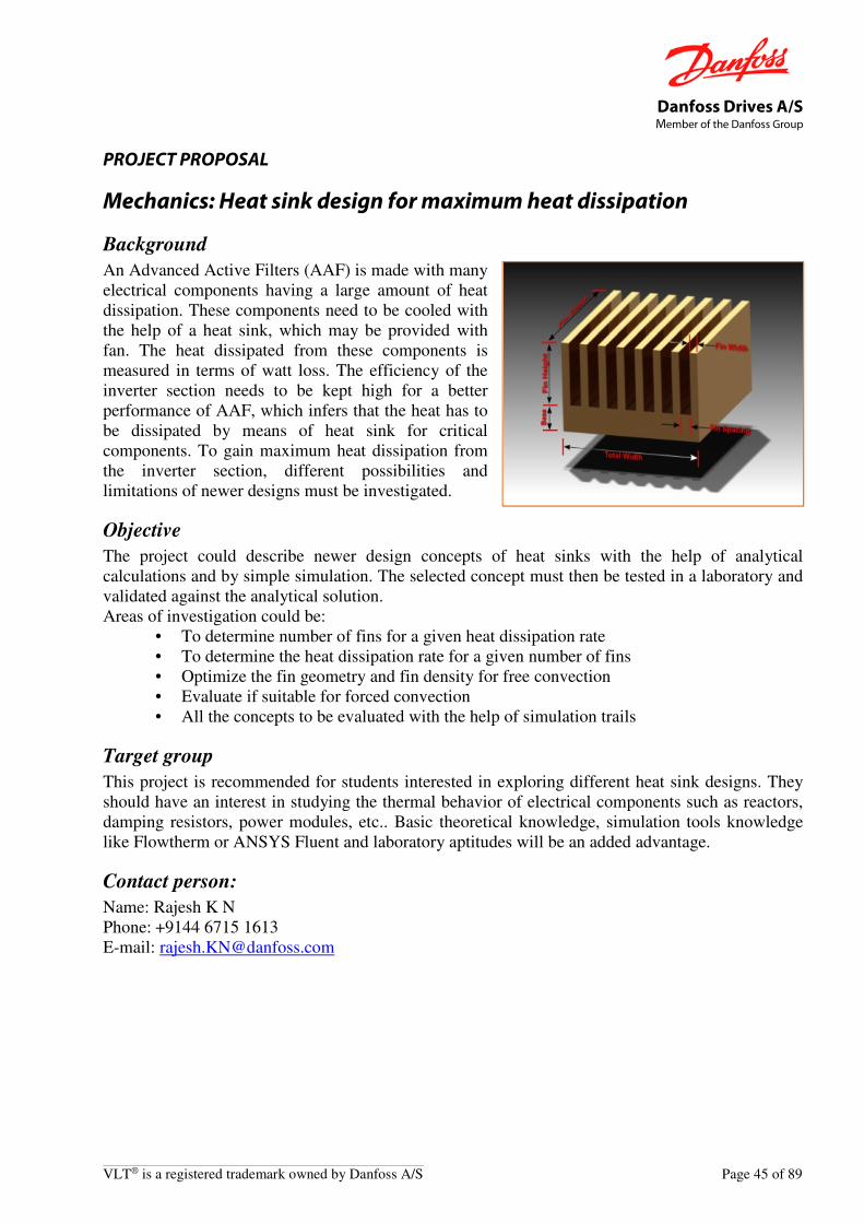
Danfoss Drives A/S Member of the Danfoss Group
VLT® is a registered trademark owned by Danfoss A/S Page 45 of 89
PROJECT PROPOSAL
Mechanics: Heat sink design for maximum heat dissipation
Background
An Advanced Active Filters (AAF) is made with many electrical components having a large amount of heat dissipation. These components need to be cooled with the help of a heat sink, which may be provided with fan. The heat dissipated from these components is measured in terms of watt loss. The efficiency of the inverter section needs to be kept high for a better performance of AAF, which infers that the heat has to be dissipated by means of heat sink for critical components. To gain maximum heat dissipation from the inverter section, different possibilities and limitations of newer designs must be investigated.
Objective
The project could describe newer design concepts of heat sinks with the help of analytical calculations and by simple simulation. The selected concept must then be tested in a laboratory and validated against the analytical solution. Areas of investigation could be:
• To determine number of fins for a given heat dissipation rate • To determine the heat dissipation rate for a given number of fins • Optimize the fin geometry and fin density for free convection • Evaluate if suitable for forced convection • All the concepts to be evaluated with the help of simulation trails
Target group
This project is recommended for students interested in exploring different heat sink designs. They should have an interest in studying the thermal behavior of electrical components such as reactors, damping resistors, power modules, etc.. Basic theoretical knowledge, simulation tools knowledge like Flowtherm or ANSYS Fluent and laboratory aptitudes will be an added advantage.
Contact person:
Name: Rajesh K N Phone: +9144 6715 1613 E-mail: [email protected]

Danfoss Drives A/S Member of the Danfoss Group
Page 46 of 89 VLT® is a registered trademark owned by Danfoss A/S
PROJECT PROPOSAL
Mechanics: Heat sink optimization
Background
In power electronics cooling applications, heat pipes are being extensively used to take out the heat from the power semiconductor devices. The heat pipes need significant improvements on their design to improve the thermal performance and to reduce the cost.
Objective
The objective of the project is to optimize the heat pipe design in the heat sink to reduce the cost and to improve thermal performance. The main objectives are:
• Thermal concepts with heat pipes generation and evaluation • Optimization of heat pipes • Real-life implementation on selected concepts • Testing and documentation
Target group
This project is recommended for students with interest in the field of thermal analysis and testing. Also a certain theoretical background, thermal software background (Flowtherm, Ansys, etc.) and laboratory aptitudes will be an added advantage.
Contact person:
Name: Mohanraj Krishnan Phone: +9144 6715 1611 E-mail: [email protected]

Danfoss Drives A/S Member of the Danfoss Group
VLT® is a registered trademark owned by Danfoss A/S Page 47 of 89
PROJECT PROPOSAL
Mechanics: Increasing resistance against shock and vibrations
Background
A Danfoss VLT® is used in more and more different applications, e.g. mobile equipment, and therefore the market demands for robustness against different environmental influences are increasing. The existing product range of Danfoss frequency converters is in general designed to withstand shock, bump and vibrations up to a certain level. To keep the leading position on the frequency converter market, it is a wish to upgrade the existing products to have an increased resistance against shock, bump and vibrations. As there also is a severe competition on the market for frequency converters, the upgrade has to be done in a very cost effective way.
Objective
The objective of this project is to investigate and uncover the weak areas on one or more of the products, and come up with solutions that could meet the demands for resistance against 2.0G in a cost effective way. Areas of investigation could be:
• Vibration and shock test of existing product/products
• Simulation of existing products using FEA
• Identification of areas that has to be re-designed
• Solutions for upgrading of product/products
• Simulation of redesign using FEA
• Test and verification of solutions
• Evaluation – covering pros & cons, risk, cost
Target group
This project is recommended for students in the middle part of the education with interest in mechanical/mechatronic design, or the use of simulation tool to verify an idea before testing.
Contact person:
Name: Jens H. Krog Phone: +45 7488 2366 E-mail: [email protected]

Danfoss Drives A/S Member of the Danfoss Group
Page 48 of 89 VLT® is a registered trademark owned by Danfoss A/S
PROJECT PROPOSAL
Mechanics: Lifetime expectancy for fans with “slide bearing”.
Background
The fans in the current Danfoss VLT® frequency converters are supplied with “ball bearings”. Due to cost saving potential we consider starting to use fans with “slide bearings” or other types. But the bearing is a critical part in a fan. When a fan breaks down it is mostly because of failure in the bearings. The fan supplier guarantees long lifetime expectancy for fans with “slide bearing”, but we still have doubts whether the bearing can cope with industrial environments.
Objective
The objective of this project is to investigate whether fans with other than ball bearings (e.g. “slide bearings”) can stand the lifetime requirement in environment with: dirt, moisture, acid and alkaline cleaning fluid and downpour water from cleaning. Areas of investigation could be:
• Contact with fan supplier.
• Available bearing types.
• Pros and cons of bearing type.
• Failure mechanisms in bearings.
• Test for dust/dirt.
• Downpour water.
• Test for acid and basic cleaning.
• Planning of field test.
Target group
This project is intended for students in the final semester with interest in reliability and/or fan-/bearing technology.
Contact person:
Name: Jens H. Krog Phone: +45 7488 2366 E-mail: [email protected]

Danfoss Drives A/S Member of the Danfoss Group
VLT® is a registered trademark owned by Danfoss A/S Page 49 of 89
PROJECT PROPOSAL
Mechanics: Metal/other materials integrated in moulded plastics
Background
The success of designing a Danfoss Variable Frequency Drive (VLT®) is very much depending on smart design. One of the key challenges is to create multi-functional parts/designs, providing several different functions in the same part/design. If we e.g. need a cover to protect the internal electrical components from external influences, we can at the same time integrate solutions for e.g. guiding of cables, guiding/fixation of printed circuit boards, mechanical fixation of the cover itself without using screws. The possibilities for smart design features are numerous...
Objective
The objective of the project is to identify materials and technologies for creation of smart designs and to demonstrate their potential. Areas of investigation in the project could be:
• Which technologies are available for molding plastics with inserts like cables/wires/busbars, threaded inserts, stand-offs, heat spreaders, gaskets, … (Examples could be insert-molding, 2K-moulding, …)
• Which technologies are available for applying electrical circuits (copper tracks and components) on/in plastic parts?
Evaluation of issues like reliability, manufacturability, cost, investments of the respective technologies should be covered in the project.
Target group
This project is recommended for students in the 3rd to 7th semester with interest in molding technologies, mechanical design and electro-mechanical integration.
Contact person:
Name: Jens H. Krog Phone: +45 7488 2366 E-mail: [email protected]
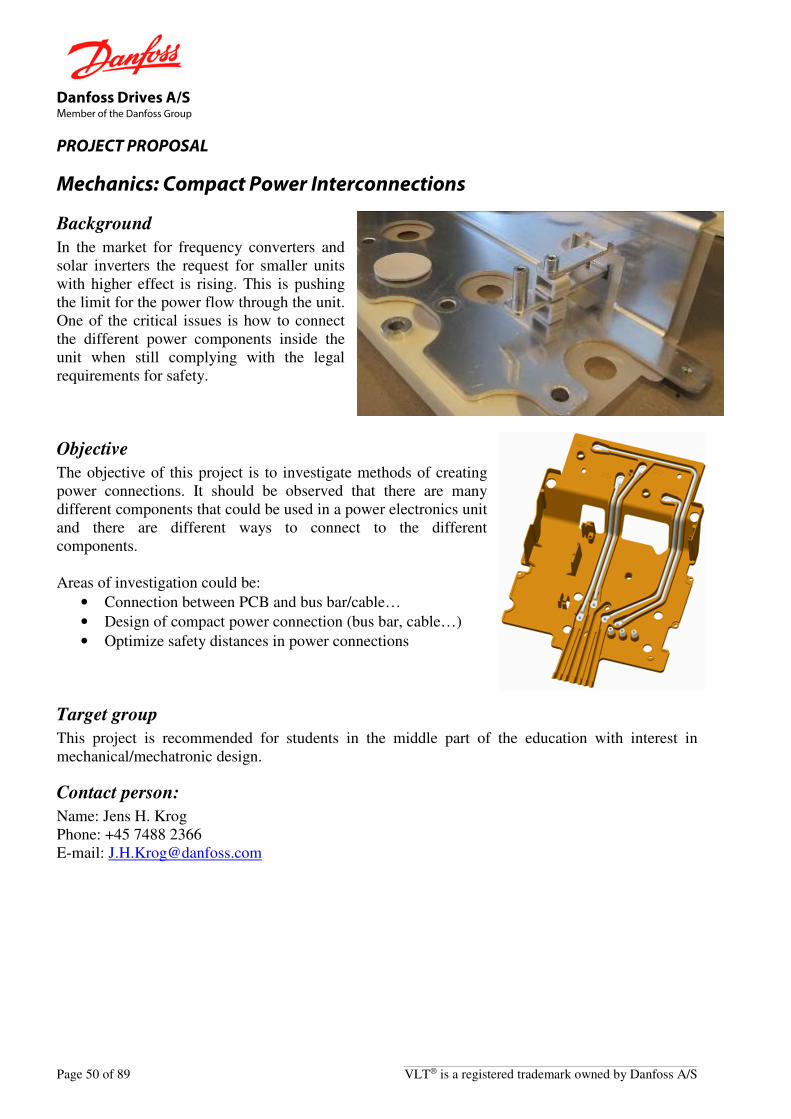
Danfoss Drives A/S Member of the Danfoss Group
Page 50 of 89 VLT® is a registered trademark owned by Danfoss A/S
PROJECT PROPOSAL
Mechanics: Compact Power Interconnections
Background
In the market for frequency converters and solar inverters the request for smaller units with higher effect is rising. This is pushing the limit for the power flow through the unit. One of the critical issues is how to connect the different power components inside the unit when still complying with the legal requirements for safety.
Objective
The objective of this project is to investigate methods of creating power connections. It should be observed that there are many different components that could be used in a power electronics unit and there are different ways to connect to the different components. Areas of investigation could be:
• Connection between PCB and bus bar/cable…
• Design of compact power connection (bus bar, cable…)
• Optimize safety distances in power connections
Target group
This project is recommended for students in the middle part of the education with interest in mechanical/mechatronic design.
Contact person:
Name: Jens H. Krog Phone: +45 7488 2366 E-mail: [email protected]

Danfoss Drives A/S Member of the Danfoss Group
VLT® is a registered trademark owned by Danfoss A/S Page 51 of 89
PROJECT PROPOSAL
Mechanics: Reducing contact resistance in terminal connections.
Background
The connection of high current components inside larger VLT® Frequency Converters is made by different types of screw / terminal connections. The terminals themselves are often made from copper with a Tin (Sn) coating. Copper is chosen for its low internal resistance and tin is applied to prevent the copper from corroding. Today this is the most feasible solution. From an electrical point of view, it is important to keep the resistance of the connection on a minimum level to avoid voltage drop and heat generation: voltage drop affects the functionality of the electronics, and heat affects the overall lifetime and operating conditions for the electronics.
Objective
The objective of the project is to find new surface treatments, surface structures or mechanical terminal designs which can provide better electrical contact than the current Tin-plated copper terminals. The solution(s) must still be resistive against corrosion and should be cost effective and suited for mass production.
Target group
This project is recommended for students in the 4th to 7th semester with interest in material science and (electro)mechanical design.
Contact person:
Name: Jens H. Krog Phone: +45 7488 2366 E-mail: [email protected]

Danfoss Drives A/S Member of the Danfoss Group
Page 52 of 89 VLT® is a registered trademark owned by Danfoss A/S
PROJECT PROPOSAL
Mechanics: Replacement of labels with other technologies
Background
The current Danfoss VLT® frequency converter uses printed sticker labels to show type codes, caution messages, manufacturer names, power rating, approvals (UL, CSA, CE, …) etc.. This might not be the optimum solution and this is often problematic for a rational and profitable production. A solution based on other technologies is expected to be cheaper. The sticker labels have the dis-advantage of potentially being mixed up – resulting in applying the wrong sticker on the product.
Objective
The objective of the project is to investigate new and alternative ways of labeling for showing information about the drive. Today the foils/labels are manually put on the enclosures that consist of plastic, aluminum or sheet metal. The new technology must show improvements on quality and cost, and maintaining the requirements for resistance to heat, oil, chemical cleaning, etc. Areas of investigation could be:
• Analyze of marking needs
• Technology screening
• Evaluation of samples
• Conclusions, recommendation for Danfoss setups
Target group
This project is intended for students in the first half study with interest in production process technologies.
Contact person:
Name: Jens H. Krog Phone: +45 7488 2366 E-mail: [email protected]

Danfoss Drives A/S Member of the Danfoss Group
VLT® is a registered trademark owned by Danfoss A/S Page 53 of 89
PROJECT PROPOSAL
Mechanics: Smart Creo* functionality.
* Creo – formerly known as Pro/ENGINEER
Background
At Danfoss Drives A/S we have used Creo for many years, as our main 3D CAD system for mechanical design. It is used at all our global development sites from the concept and analysis phase through detailed design phase to manufacturing - internally at Danfoss Drives as well as externally at collaboration partners:
• Development engineers create mechatronic designs including analysis with FEM and CFD simulation tools.
• Production technicians use Creo for making production equipment (fixtures, test equipment etc.).
• Marketing use the assemblies (pictures) for technical literature.
• External partners use our Creo files for e.g. tool manufacturing, outsourced design tasks, …
This means that Creo objects are extensively (simultaneously) reused, requiring simple and robust models and strict data control. Much time is spent in front of the CAD screen, and even small improvements in the development flow will increase efficiency significantly.
Objective
Investigate the possibilities of reducing the development time by optimizing the way to use Creo. Areas of investigation could be:
• Use of the analysis facilities (Behavioral Modeling, Pro/Mechanica, Excel/MathCAD integration) in order to reduce the number of prototypes and failures in the development phase.
• Use of “Bottom up Design” versus “Top down Design” (incl. “skeletons”) identifying pros and cons and the potentials.
• Creation of smarter user interface (map keys, toolbars etc.), templates, …
• Creation of family tables of standard parts (e.g. screws, washers, connectors, …)
• Improvement potentials within data management (PDMlink)
• Improvement potentials of using Creo integrated with ArborText for technical literature
Contact Person:
Name: Jens H. Krog Phone: +45 7488 2366 E-mail: [email protected]

Danfoss Drives A/S Member of the Danfoss Group
Page 54 of 89 VLT® is a registered trademark owned by Danfoss A/S
PROJECT PROPOSAL
Mechanics: Thermal Interface material (TIM)
Background
The Power density (Power / area) of Power modules is getting higher and higher. This makes it more difficult to keep the temperature of the Chip at an acceptable level. To minimize the thermal resistance between the heat spreader of the Power module (Copper base plate) and the heat sink, it is necessary to use Thermal Interface material (TIM).
Objective
The objective is to make a survey of the market: - Which TIM is commercially available at the moment? - Are there any new interesting materials under development? - Compare the properties of the different TIM (thermal-, environmental-, handling in high
volume production, storing-, price, etc.) with the once we are using today. - Test some different TIM, and compare the theoretical and measured temperatures.
Target group
This project is recommended for students in the middle or end of their semester with interest in Thermal management and Heat-transfer.
Contact person:
Name: Jens H. Krog Phone: +45 7488 2366 E-mail: [email protected]
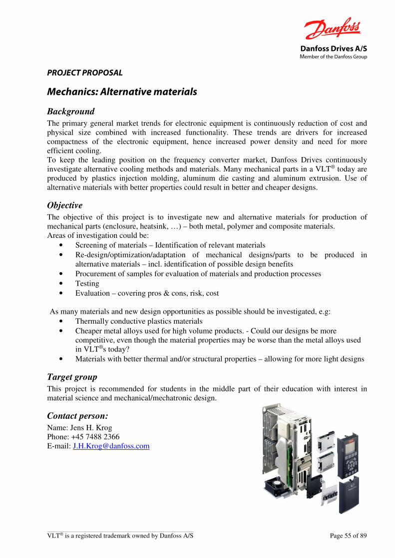
Danfoss Drives A/S Member of the Danfoss Group
VLT® is a registered trademark owned by Danfoss A/S Page 55 of 89
PROJECT PROPOSAL
Mechanics: Alternative materials
Background
The primary general market trends for electronic equipment is continuously reduction of cost and physical size combined with increased functionality. These trends are drivers for increased compactness of the electronic equipment, hence increased power density and need for more efficient cooling. To keep the leading position on the frequency converter market, Danfoss Drives continuously investigate alternative cooling methods and materials. Many mechanical parts in a VLT® today are produced by plastics injection molding, aluminum die casting and aluminum extrusion. Use of alternative materials with better properties could result in better and cheaper designs.
Objective
The objective of this project is to investigate new and alternative materials for production of mechanical parts (enclosure, heatsink, …) – both metal, polymer and composite materials. Areas of investigation could be:
• Screening of materials – Identification of relevant materials
• Re-design/optimization/adaptation of mechanical designs/parts to be produced in alternative materials – incl. identification of possible design benefits
• Procurement of samples for evaluation of materials and production processes
• Testing
• Evaluation – covering pros & cons, risk, cost As many materials and new design opportunities as possible should be investigated, e.g:
• Thermally conductive plastics materials
• Cheaper metal alloys used for high volume products. - Could our designs be more competitive, even though the material properties may be worse than the metal alloys used in VLT®s today?
• Materials with better thermal and/or structural properties – allowing for more light designs
Target group
This project is recommended for students in the middle part of their education with interest in material science and mechanical/mechatronic design.
Contact person:
Name: Jens H. Krog Phone: +45 7488 2366 E-mail: [email protected]

Danfoss Drives A/S Member of the Danfoss Group
Page 56 of 89 VLT® is a registered trademark owned by Danfoss A/S
PROJECT PROPOSAL
Mechanics: Smart replacement of screws
Background
In modern electronics production focus is more and more on assembly time. One of the time consuming tasks in an assembly line is mounting of screws. If the number of screws is in the products are reduced, it will be faster to assemble and thereby reducing the price of the product.
Objective
The objective of this project is to investigate new methods of fastening PCB’s (Printed Circuit Boards) and other electronic components like IGBT’s in an enclosure without compromising the reliability. Areas of investigation could be:
• Investigate which fixation products are available
• Replacement of screws in aluminum heat sink
• Replacement of screws in plastic assemblies
• Other ways to fix PCB’s and other components
Target group
This project is recommended for students in the middle part of the education with interest in mechanical/mechatronic design.
Contact person:
Name: Jens H. Krog Phone: +45 7488 2366 E-mail: [email protected]

Danfoss Drives A/S Member of the Danfoss Group
VLT® is a registered trademark owned by Danfoss A/S Page 57 of 89
PROJECT PROPOSAL
Power/Economics: Three Level Voltage Source Drive for Better System Efficiency
Background
Three level voltage source drives (VSD) is a potential candidate for future power drive systems (PDS), since they have some benefits compared with the two level VSD, such as: reduces total cost of ownership for the entire system (consumed energy over life time, cost of PDS and motor), longer motor life time, longer cables without shielding, better system efficiency, etc.
Two level voltage source drives (VSD) have been used for decades to control and supply electrical machines and have been the workhorse at Danfoss. Resent development in power electronic has opened the possibility to expand into three-level VSD also for small power sizes. Basically, a two level VSD can be constructed by adding six additional transistors, as depicted below.
Objective
The objective of this project is to test the following hypothesis:
• Power Drive System (PDS) total cost of ownership will decrease,
• PDS efficiency and motor lifetime will increase,
• It will be possible to operate with longer cable between VSD and motor,
• Less or no voltage drop over motor filters,
• Less acoustic noise from motor, important in elevators and escalators,
• Applications, e.g. Chemical plants, HVAC and AQUA,
• Better shaft-performance by higher switching and control frequencies. An existing three level Solar PV inverter must be modified to operate as a three level VSD in a PDS. Simple control algorithms must be implemented in MATLAB/SIMULINK to control a motor with the three-level VSD. Measurement and evaluation according to list above must be performed.
Target group
Master students. This project will be conducted with and at Danfoss Drives A/S in Gråsten.
Contact person:
Name: Søren Bækhøj Kjær Phone: +45 3051 3414 E-mail: [email protected]
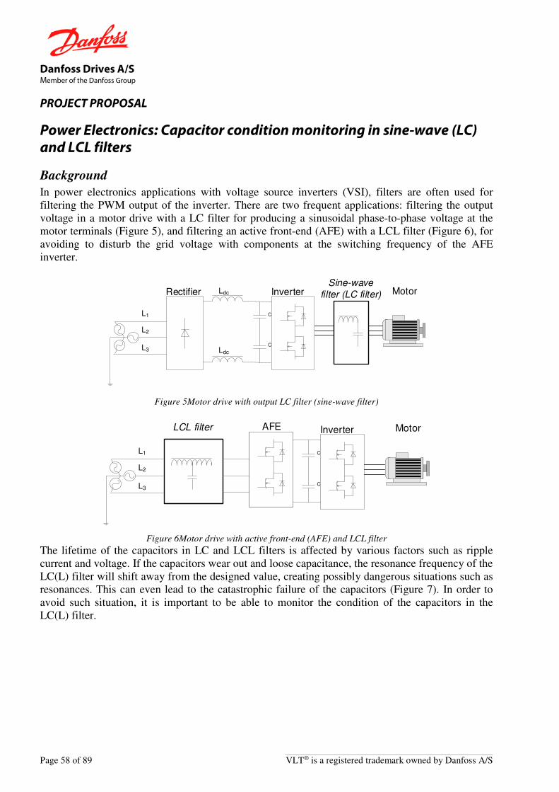
Danfoss Drives A/S Member of the Danfoss Group
Page 58 of 89 VLT® is a registered trademark owned by Danfoss A/S
PROJECT PROPOSAL
Power Electronics: Capacitor condition monitoring in sine-wave (LC) and LCL filters
Background
In power electronics applications with voltage source inverters (VSI), filters are often used for filtering the PWM output of the inverter. There are two frequent applications: filtering the output voltage in a motor drive with a LC filter for producing a sinusoidal phase-to-phase voltage at the motor terminals (Figure 5), and filtering an active front-end (AFE) with a LCL filter (Figure 6), for avoiding to disturb the grid voltage with components at the switching frequency of the AFE inverter.
C
C
Ldc
Ldc
L1
L2
L3
MotorSine-wave
filter (LC filter)InverterRectifier
Figure 5Motor drive with output LC filter (sine-wave filter)
C
C
L1
L2
L3
MotorLCL filter InverterAFE
Figure 6Motor drive with active front-end (AFE) and LCL filter
The lifetime of the capacitors in LC and LCL filters is affected by various factors such as ripple current and voltage. If the capacitors wear out and loose capacitance, the resonance frequency of the LC(L) filter will shift away from the designed value, creating possibly dangerous situations such as resonances. This can even lead to the catastrophic failure of the capacitors (Figure 7). In order to avoid such situation, it is important to be able to monitor the condition of the capacitors in the LC(L) filter.

Danfoss Drives A/S Member of the Danfoss Group
VLT® is a registered trademark owned by Danfoss A/S Page 59 of 89
Figure 7 Damaged capacitors in a LC sine-wave filter
Objective
The project has following objectives:
• Comparative overview of possible methods for condition monitoring of capacitors in LC(L) filters
• In depth analysis of a selected method (can be, for example, based on analyzing the current ripple)
• Simulation model
• Practical implementation based on dSpace system (only one of the filters is sufficient – either LC output filter or LCL filter for AFE)
Target group
This project is recommended for master students in power electronics and drives.
Reference:
1. K. W. Lee, M. Kim, J. Yoon, S. B. Lee and J. Y. Yoo, "Condition Monitoring of DC-Link Electrolytic Capacitors in Adjustable-Speed Drives," in IEEE
Transactions on Industry Applications, vol. 44, no. 5, pp. 1606-1613, Sept.-Oct. 2008. doi: 10.1109/TIA.2008.2002220
2. S. Prasanth, M. H. M. Sathik, F. Sasongko, T. C. Seng, M. Tariq and R. Simanjorang, "Online equivalent series resistance estimation method for condition monitoring of DC-link capacitors," 2017 IEEE Energy Conversion Congress and
Exposition (ECCE), Cincinnati, OH, 2017, pp. 1773-1780. doi: 10.1109/ECCE.2017.8096009.
Contact person:
Name: Norbert Hanigovszki Phone: +45 29 28 46 17 Email: [email protected]

Danfoss Drives A/S Member of the Danfoss Group
Page 60 of 89 VLT® is a registered trademark owned by Danfoss A/S
PROJECT PROPOSAL
Power Electronics: Impact of output filters on the energy efficiency of a power drive system
Background
In December 2014 the EN50598 standard on eco-design of power drive systems has been published. This standard classifies adjustable speed drives and power drive systems (drive + motor) into efficiency classes. It also defines part load operation points which can be used for determining the energy efficiency index of an application.
IE2
IE1
IE3
IE4
IE5
Standard efficiency
High efficiency
Premium efficiency
Super-premium efficiency
(Planned)
IE1
IE2
IE0
IES1
IES2
IES0
Losses relative to reference
125 %
75 %
Losses relative to reference
120 %
80 %
IEC/EN 60034-30-1 EN 50598-2Defined at 90% motor frequency and 100%
current
EN 50598-2Defined at 100% motor speed and
100% torque In some applications output filters are used between the drive and the motor in order to protect the motor or reduce acoustic noise from the motor. The use of output filters has an impact on the total energy efficiency of the system. The filter adds losses to the system, while losses in the motor are reduced. The losses in the drive are partly decreased because of the elimination of switching current ringing but they can also increase if the output filter requires a higher switching frequency or a certain switching pattern. The impact of the output filter on the efficiency of the power drive system and the specific impact on the energy efficiency classification of the complete drives module (drive + filter) and power drive system (drive + filter + motor) has not been yet investigated.
Objective
The objective of this project is to:
• Analyze the losses in the drive and the impact of the output filter
• Analyze the losses in the output filter
• Conduct experimental tests to determine the impact of various parameters such as switching frequency and modulation pattern
• Perform a comparison with standardized reference values from EN50598 • Draw conclusions and propose recommendations for future work

Danfoss Drives A/S Member of the Danfoss Group
VLT® is a registered trademark owned by Danfoss A/S Page 61 of 89
Target group
Bachelor/master students. This project will be conducted with Danfoss Drives A/S in Gråsten.
Contact person:
Name: Norbert Hanigovszki Phone: +45 7443 4148 E-mail: [email protected]
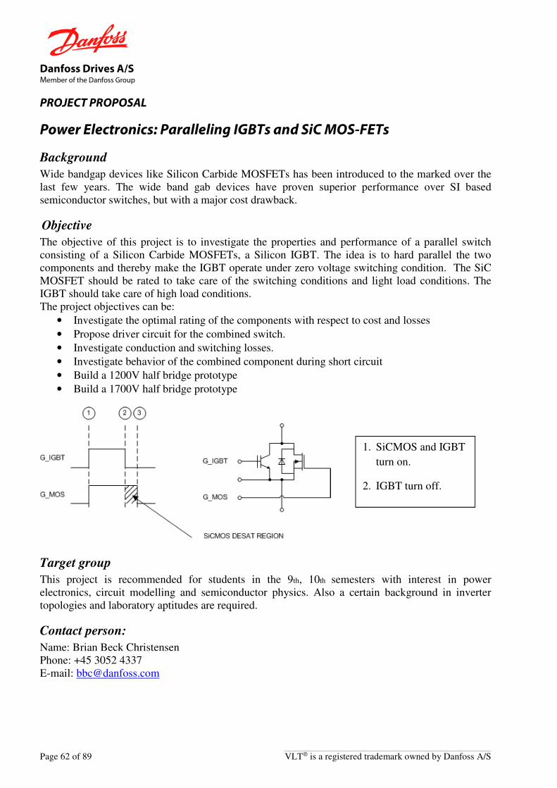
Danfoss Drives A/S Member of the Danfoss Group
Page 62 of 89 VLT® is a registered trademark owned by Danfoss A/S
PROJECT PROPOSAL
Power Electronics: Paralleling IGBTs and SiC MOS-FETs
Background
Wide bandgap devices like Silicon Carbide MOSFETs has been introduced to the marked over the last few years. The wide band gab devices have proven superior performance over SI based semiconductor switches, but with a major cost drawback.
Objective
The objective of this project is to investigate the properties and performance of a parallel switch consisting of a Silicon Carbide MOSFETs, a Silicon IGBT. The idea is to hard parallel the two components and thereby make the IGBT operate under zero voltage switching condition. The SiC MOSFET should be rated to take care of the switching conditions and light load conditions. The IGBT should take care of high load conditions. The project objectives can be:
• Investigate the optimal rating of the components with respect to cost and losses
• Propose driver circuit for the combined switch.
• Investigate conduction and switching losses.
• Investigate behavior of the combined component during short circuit
• Build a 1200V half bridge prototype
• Build a 1700V half bridge prototype
Target group
This project is recommended for students in the 9th, 10th semesters with interest in power electronics, circuit modelling and semiconductor physics. Also a certain background in inverter topologies and laboratory aptitudes are required.
Contact person:
Name: Brian Beck Christensen Phone: +45 3052 4337 E-mail: [email protected]
1. SiCMOS and IGBT
turn on.
2. IGBT turn off.

Danfoss Drives A/S Member of the Danfoss Group
VLT® is a registered trademark owned by Danfoss A/S Page 63 of 89
PROJECT PROPOSAL
Power Electronics: Auxiliary power supply design with SiC MOSFETs
Background
A general trend within motor drives is to increase the power density by making the drives more efficient (smaller size or increase the output power). These requirements also affect the auxiliary power supply design of the drive. SiC components have been introduced to the marked over the recent years and in this project, we would like to investigate the benefits of wide bandgap devices (SiC) in the auxiliary power supply design for low voltage drives.
Objective
Investigate the benefits of SiC semiconductor switches in the auxiliary power supply and investigate the topologies that are best suited for the use with SiC semiconductors. The objective of the project is to create a high efficiency and low loss design for the power supply without active cooling (no fan) and heatsink. Requirements:
• Input voltage range: 300 – 1000 Vdc
• Output 1: 24V/40W (PELV)
• Output 2: 18V/20W (functional isolation)
• Compact size and minimal footprint Deliverables:
• Optimal topology
• Efficiency curve of the power supply
• Cost break down
Target group
This project is recommended for students in the 9th, 10th semesters with interest in power electronics, circuit modelling and semiconductor physics. Also a certain background in inverter topologies and laboratory aptitudes are required.
Contact person:
Name: Brian Beck Christensen Phone: +45 3052 4337 E-mail: [email protected]

Danfoss Drives A/S Member of the Danfoss Group
Page 64 of 89 VLT® is a registered trademark owned by Danfoss A/S
PROJECT PROPOSAL
Power Electronics: Measurement of junction temperatures
Background
An importance parameter for motor drives is the uptime and lifetime of a product when exposed to a given load cycle. It is of significant importance to detect wear outs before they become critical in order to initiate preventive maintenance. An important measure for this is the junction temperature of IGBTs in the power modules.
Objective
The objective of the project is to create a gate driver or an add on circuit that is able to measure the junction temperature “on the fly” direct or indirect in a cost-effective way. Examples can be found in the literature covering:
• Resistance change of on chip gate resistor either during turn off or by AC injection in to the gate.
• Mapping of Vce(on) as function of temperature and current.
Target group
This project is recommended for students in the 9th, 10th semesters with interest in power electronics, circuit modelling and semiconductor physics. Also, a certain background in inverter topologies and laboratory aptitudes are required.
Contact person:
Name: Brian Beck Christensen Phone: +45 3052 4337 E-mail: [email protected]

Danfoss Drives A/S Member of the Danfoss Group
VLT® is a registered trademark owned by Danfoss A/S Page 65 of 89
PROJECT PROPOSAL
Power Electronics: Power Cables Evaluation for VFDs
Background
Power cable is playing vital role in VFD applications. As on today, we have limited awareness on power cables used in VFD Industrial applications. Different cable manufacturers recommend different types of cables, ratings, spacing factors and layout procedures. At the same time standard bodies are coming out with new standards which are varying from on region to another region. A standard design guide for power cables are missing and hence it’s required to do Power Cables Evaluations for VFD applications
Objective
The objective of the project is to evaluate power cables for VFD applications focusing on cable types, electrical & magnetics parameters, effect of cable length, number cables in parallel, cable layout, reflected voltage and Common Mode Noise etc.
Target group
This project is intended for students in the 2nd year PG students – Power Electronics and Drives or PhD students in Electrical Engineering
Contact person:
Name: Shanmugam Paramasivam Phone: +9144 6715 1486 E-mail: [email protected]
Danfoss Drives A/S Member of the Danfoss Group
Page 66 of 89 VLT® is a registered trademark owned by Danfoss A/S
PROJECT PROPOSAL
Power Electronics: DC link capacitor soft-charge using three phase buck converters
Background
The modernization of VFD drives is mainly focused on achieving high power density. The technology gets improved in reducing the power loss in individual components all around the drive system. One of the very few unchangeable parameters is the value of the DC link capacitance. Even though the power and energy density of the capacitor is increased through the modern capacitor technology, the inrush current drawn by the capacitors cannot be modified. In the traditional VFD circuits, the input diode bridge is set in series with a resistor which is bypassed after startup. In this way the capacitor inrush current is limited by the resistor. Even though the resistor faces the soft-charge current for a little duration, the energy handled by the resistor is very high. So, the size of the resistor is also high which increases the cost and required space in the drive. Some active soft-charge systems are already available, but the control techniques and requirement of inductors are challenging when using in diode front end rectifiers. This requires a new concept which can be used as a standalone soft-charge system which will require a simple control technique and reduced inductance.
Objective
The objective of this project is to investigate a new soft-charge system using a three-phase buck converter with IGBTs and developing the control circuit for it. Areas of investigation could be:
• Analysis & simulation of the three-phase buck converter as a soft-charge system • Design of the three-phase buck converter based soft-charge circuit and selection of
devices • Defining the control system using micro controller based circuit • Prototype built (PCA, Programming, verification) and proof of concept • Checking the feasibility of using in the high-power drive system
Target group
This project is recommended for post-graduate students in the final semester.
Contact person:
Name: Rengamuni Govarthanan Phone: +9144 6715 1419 E-mail: [email protected]

Danfoss Drives A/S Member of the Danfoss Group
VLT® is a registered trademark owned by Danfoss A/S Page 67 of 89
PROJECT PROPOSAL
Power Electronics: Advanced Active Filter (AAF) with reduced DC link voltage
Background
In recent years, voltage and current harmonics are become serious problem in transmission and distribution systems. To eliminate these voltage and current harmonics and to achieve clean grids, AAFs are being used. The existing AAF technology requires a higher DC link voltage to achieve the THDi requirement. The figure below shows a typical AAF block diagram consisting of LCL network, IGBT section and DC-link capacitor bank.
Objective
The objective of this project is to do the literature survey, analyze, propose and prove a concept for AAFs with reduced DC link voltage (LCL network should be part of the system). MATLAB based simulation should be carried out for the proposed concept to verify the results.
Target group
This project is recommended for students with interest in power electronics and their control. Acknowledge and familiarity of MATLAB/Simulink is required.
Contact person:
Name: Neelam Sujith Kumar Phone: +9144 6715 1963 E-mail: [email protected]

Danfoss Drives A/S Member of the Danfoss Group
Page 68 of 89 VLT® is a registered trademark owned by Danfoss A/S
PROJECT PROPOSAL
Power Electronics: Filter design to mitigate the voltage distortions in (2-9) kHz range
Background
In existing Advanced Active Filters for higher power, IGBTs are being switched at high switching frequencies in the range of (2-9) kHz with constant or variable switching frequencies depending upon the manufacturers. Due to these high switching frequencies, input voltage is being distorted with high frequency components which are exceeding recommended IEC 61000-2-4 limits. IEC 61000-2-4 standard defines discrete and 200Hz grouping method with recommended limits. To mitigate these voltage distortions in (2-9) kHz range, it is required to design and develop a filter.
Objective
The objective of this project is to design and develop a filter that can mitigate the voltage distortions in (2-9) kHz range. The designed filter should not create any resonance issues with the system. The filter should be cost effective with optimum performance. It should reduce the voltage distortions within specified limits by IEC 61000-2-4 with both discrete and 200Hz grouping methods. Areas of investigation could be:
• Study of IEC 61000-2-4 standard • Literature survey of existing filters • Design and development of the new filter • Validation of the filter with respect to IEC 61000-2-4 limits
Target group
This project is recommended for students with interest in power electronics and power systems. Knowledge in magnetics and familiarity of MATLAB/Simulink is required.
Contact person:
Name: Neelam Sujith Kumar Phone: +9144 6715 1963 E-mail: [email protected]

Danfoss Drives A/S Member of the Danfoss Group
VLT® is a registered trademark owned by Danfoss A/S Page 69 of 89
PROJECT PROPOSAL
Power Electronics: Alternative to the Hall-Based Current Transducer.
Background
Current-sensing is an important technology in a frequency converter like the VLT® AutomationDrive FC 30x from Danfoss Drives A/S. It defines the control-performance quality of the drive. And it defines the robustness and quality of the drive, since the current-sensing signals are used for protection also. A fundamental issue is whether the current-sensing should offer galvanic isolation or not. In high-performance drives galvanic isolation is typically required. In this case, the default choice of current-sensing technology is the Hall-based current transducer. A problem of the Hall transducer is the Hall element inserted in the gap of the magnetic core. Though the overall construction is simple, history shows that a high-quality in running production is difficult to maintain. Recently, a new magnetic current-sense technology has been reported, where the Hall element in the gapped core is not needed. The topology is a simple 1-phase transformer with PWM modulated secondary side enabling the device to sense both AC and DC-currents.
Objective
1) To analyze the principles of a Hall-based current transducer in detail from a hardware and control point of view.
2) To analyze the principle of the PWM-modulated current-sense transformer. 3) To build a simulation model in SABER. 4) To build a lab model and verify the performance. 5) To analyze the potential bandwidth and accuracy of the technology. 6) To base the device on 5V technology.
Target group
This project is recommended for students in the 5th to 10th semester with interest in power electronics.
Contact person:
Name: Henrik Rosendal Andersen Phone: +45 7488 2582 Email: [email protected]

Danfoss Drives A/S Member of the Danfoss Group
Page 70 of 89 VLT® is a registered trademark owned by Danfoss A/S
PROJECT PROPOSAL
Power Electronics: Accelerated lifetime test on electrolytic capacitors
Background
The frequency converter lifetime is highly dependent of the lifetime of the DC-Link capacitors. Today the designer has to rely on theoretical equations for lifetime calculations. The lifetime equations vary from different manufacturers as the equations are based on the capacitor manufacturers’ experience. Therefore, it is very difficult to compare capacitor lifetime between manufacturers.
Objective
The objective of the project is to develop a method to accelerate lifetime test without changing the chemical behavior inside the capacitor. The project is made in co-operation with one or two leading manufacturers of capacitors.
Target group
This project is recommended for students in the 5th to 10th semester with interest in hardware and component technology.
Contact person:
Name: John Rohwedder Phone: +45 7488 3637 E-mail: [email protected]

Danfoss Drives A/S Member of the Danfoss Group
VLT® is a registered trademark owned by Danfoss A/S Page 71 of 89
PROJECT PROPOSAL
Power Electronics: Mains Phase unbalance compensate system
Background
The current ripple in the DC-link capacitors increases very much if there is unbalance between the three mains phases. Therefore, if the frequency converter is able to compensate for this unbalance it will be possible to run at very bad power lines.
Objective
The objective of the project is to investigate in methods to reduce the impact of the mains unbalance. The methods should be used to develop a program to the active µ -processor based inrush. The program will be tested in our 90kW VLT®
Target group
This project is recommended for students in the 5th to 10th semester with interest in both hardware and software.
Contact person:
Name: John Rohwedder Phone: +45 7488 3637 E-mail: [email protected]

Danfoss Drives A/S Member of the Danfoss Group
Page 72 of 89 VLT® is a registered trademark owned by Danfoss A/S
PROJECT PROPOSAL
Power Electronics: Intelligent two-level turn-off of power modules in frequency converter
Background
In case of short circuit or overcurrent on the output of the frequency converter, a large voltage overshoot can occur across the IGBT at turn-off, and hereby exceed the IGBT breakdown voltage and RBSOA ratings. By reducing the gate voltage before turn-off, the IGBT current is limited and the potential over voltage is reduced. This technique is called two-level turn-off and is used to increase reliability of the frequency converter. This two-level turn-off sequence should ideally only take place during over current and not during normal run. Today two-level turn-off is active all the time.
Objective
• To analyze the benefit of not having two-level turn-off in normal run
• To develop a circuit that uses the signal from the current transducers in the Drive and control the gate drive IC TD350 to turn on and off the 2-Level voltage level at the IGBT gate.
• To build a simulation model of the circuit.
• Build lab model of circuit into a modified drive.
• Make test in the lab.
Target group
This project is recommended for students in the 5th to 10th semester with interest in power electronics.
Contact person:
Name: John Rohwedder Phone: +45 7488 3637 E-mail: [email protected]
Voltage to the IGBT
gate with two-level
turn-off

Danfoss Drives A/S Member of the Danfoss Group
VLT® is a registered trademark owned by Danfoss A/S Page 73 of 89
PROJECT PROPOSAL
Power Electronics: Implementing two-level turn-off of IGBT using advanced FPGA-based gate-drive controller
Background
In case of short circuit or overcurrent on the output of the frequency converter, a large voltage overshoot can occur across the IGBT at turn-off, and hereby exceed the IGBT breakdown voltage and RBSOA ratings. By reducing the gate voltage before turnoff, the IGBT current is limited and the potential over voltage is reduced. This technique is called two-level turn-off and is used to increase reliability of the frequency converter. By using special techniques, the disadvantages with the normal two-level turn off implementation like, delay in control loop and higher deadtime distortion can be eliminated. Furthermore, a cost reduction compared to the solution implemented today is expected.
Objective
• To analyze and optimize proposed concept.
• Propose different solutions to implement gate-driver without TD350.
• To build a simulation model of the circuit and prove concept.
• Build lab model of circuit.
• Implement complete gate-drive controller in FPGA.
• Implement circuit in existing VLT.
• Make test in the lab.
Target group
This project is recommended for students in the 5th to 10th semester with interest in power electronics.
Contact person:
Name: Finn Borup Phone: +45 7488 3804 Email: [email protected]

Danfoss Drives A/S Member of the Danfoss Group
Page 74 of 89 VLT® is a registered trademark owned by Danfoss A/S
PROJECT PROPOSAL
Power Electronics: Cost effective current sensors
Background
Current sensing and measurement is an important technology in almost all power electronic applications, for control and protection purposes. Nowadays power electronics, like the Danfoss VLT® drives, are typically sold in highly competitive markets, and cost is an essential issue. The cost involved in current sensing is relatively high, depending on complexity and desired performance of the current measurement. Different performance levels of current measurement can be identified, depending on drive control performance and for what purposes the current measurements are used. The simplest known principle with the simplest known implementation for current measurement is to measure the voltage across a copper–track on a PCB, as a measure for the current flowing through the cobber-track. This implementation has a potential for being very cost effective, but also has several well-known drawbacks. This project proposal is about to investigate how good can a PCB based copper-track implementation of a current measurement get, while still keeping low cost in mind.
Objective
1) To analyze the principles and drawbacks for PCB copper-track current sensing. 2) To analyze the necessary measurement circuits. 3) To analyze necessary calibrations, and suggest implementable solutions. 4) To analyze necessary compensations circuits, and suggest implementable solutions. 5) To analyze the dynamic performance of the sensing principle. 6) To estimate effect of drawbacks on protection of power semiconductors. 7) To analyze the achievable precision, based on 1) – 5) 8) To make suggestions for the physical layout of the sensing principle, based on 1) – 5). 9) To base solutions on low cost principles for all involved techniques and sub-designs. 10) To base proposals on solutions that can be implemented in a VLT® drive. 11) To build a lab model and verify the performance.
Target group
This project is recommended for students in the 5th to 10th semester with interest in mechatronics or power electronics.
Contact person:
Name: Peter Manner-Jakobsen Phone: +45 7488 4952 Email: [email protected]

Danfoss Drives A/S Member of the Danfoss Group
VLT® is a registered trademark owned by Danfoss A/S Page 75 of 89
PROJECT PROPOSAL
Power Electronics: Active Filter Based Electronic Smoothing Inductor – New Topology and Control - Solution used to reduce the size of DC Link in Frequency Converters
Background
Three phase electric drives consist of a three-phase power conversion stage AC/DC (very common by using diodes and/or thyristors), followed by a DC Link circuit, and the DC/AC power inverter stage conversion. The rectifier draws significant amounts of harmonic currents from the grid system. In order to reduce the induced harmonic distortion in the power network, on can add a large DC or AC inductance, but with the drawback of added volume (Watts/inch3) for the overall drive, and also of a slow dynamic behavior. Another possibility is to use the active switches at the rectification stage which can shape unity power factor currents, but this adds extra cost and has inherent extra losses. The Electronic Smoothing Inductor (ESI) is used for the reduction of overall size of a diode bridge based three phase electric drive. By adding a smaller standard inductor inside the DC Link circuit and controlling the DC Link current a new topology is created. The newly topology referred to as Active Filter Electronic Smoothing Inductor (AFESI) combines both techniques of Active Harmonic Filter and Electronic Smoothing Inductor inside of the DC-link circuit to control the DC-link current.
The AFESI power circuit and proposed control block
Objective
The objective of this project is to investigate the electrical design and control of the circuit. The circuit should be evaluated in case of transients input voltage, inrush, mains dips as comparative performance with classic DC Link solutions.

Danfoss Drives A/S Member of the Danfoss Group
Page 76 of 89 VLT® is a registered trademark owned by Danfoss A/S
Target group
This project is recommended for students with interest in power electronics and their control. A knowledge and familiarity of MATLAB/Simulink is required.
Contact person:
Name: Lucian Asiminoaei Phone: +45 7488 7051 Email: [email protected]
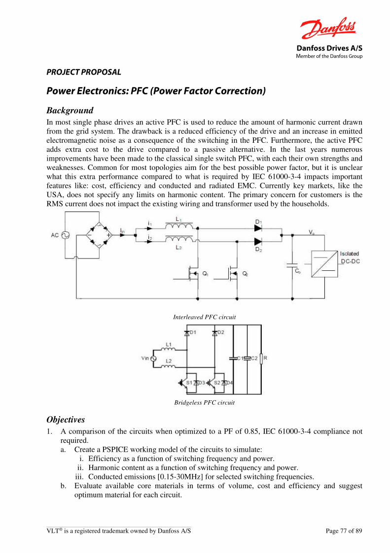
Danfoss Drives A/S Member of the Danfoss Group
VLT® is a registered trademark owned by Danfoss A/S Page 77 of 89
PROJECT PROPOSAL
Power Electronics: PFC (Power Factor Correction)
Background
In most single phase drives an active PFC is used to reduce the amount of harmonic current drawn from the grid system. The drawback is a reduced efficiency of the drive and an increase in emitted electromagnetic noise as a consequence of the switching in the PFC. Furthermore, the active PFC adds extra cost to the drive compared to a passive alternative. In the last years numerous improvements have been made to the classical single switch PFC, with each their own strengths and weaknesses. Common for most topologies aim for the best possible power factor, but it is unclear what this extra performance compared to what is required by IEC 61000-3-4 impacts important features like: cost, efficiency and conducted and radiated EMC. Currently key markets, like the USA, does not specify any limits on harmonic content. The primary concern for customers is the RMS current does not impact the existing wiring and transformer used by the households.
Interleaved PFC circuit
Bridgeless PFC circuit
Objectives
1. A comparison of the circuits when optimized to a PF of 0.85, IEC 61000-3-4 compliance not required. a. Create a PSPICE working model of the circuits to simulate:
i. Efficiency as a function of switching frequency and power. ii. Harmonic content as a function of switching frequency and power.
iii. Conducted emissions [0.15-30MHz] for selected switching frequencies. b. Evaluate available core materials in terms of volume, cost and efficiency and suggest
optimum material for each circuit.

Danfoss Drives A/S Member of the Danfoss Group
Page 78 of 89 VLT® is a registered trademark owned by Danfoss A/S
2. A comparison of the circuits when optimized to simply comply with IEC 61000-3-4 a. Create a PSPICE working model of the circuits to simulate:
i. Efficiency as a function of switching frequency and power. ii. Harmonic content as a function of switching frequency and power.
iii. Conducted emissions [0.15-30MHz] for selected switching frequencies. b. Evaluate available core materials in terms of volume, cost and efficiency and suggest
optimum material for each circuit. 3. To build a lab model and verify the performance of circuits
Target group
This project is recommended for students with interest in power electronics and their control.
Contact person:
Name: Hans Christian Holm Phone: +45 7488 4863 Email: [email protected]

Danfoss Drives A/S Member of the Danfoss Group
VLT® is a registered trademark owned by Danfoss A/S Page 79 of 89
PROJECT PROPOSAL
Power Electronics: Automatic test setup for electrical characterization of power modules from 0.25kW to 90kW
Background
The power modules used today in frequency converters are coming in a variety of power sizes and casings. Before being used in a frequency converter the power devices are typically qualified by measuring their electrical properties. These measurements are typically done under static and dynamic conditions. The static analysis is done by use of curve tracers or direct measurements under static conditions. The dynamic characterization is typically testing the dynamic behavior of the device like switching times, switching losses, short-circuit behavior or even extracting the parasitic capacities.
Objective
The main objective of this project is to design and demonstrate an automatic test system for electrical characterization of power modules in the power range from 0.25kW to 90kW. The system should be able to do the test fully automatic after entering the test parameters and under different temperature conditions. The hardware should be flexible in order to accommodate a series of power modules with different encapsulations
Target group
This project is recommended for students in the 8th to 10th semester with interest in power electronics and drives.
Contact person:
Name: Radu Lazar Phone: +45 7488 1846 Email: [email protected]

Danfoss Drives A/S Member of the Danfoss Group
Page 80 of 89 VLT® is a registered trademark owned by Danfoss A/S
PROJECT PROPOSAL
Reliability: Diagnostic and prognostic methods
Background
Predictability and a high up-time of frequency converters and solar inverters are important for customers to control TCO (Total Cost of Ownership).
Diagnostic and prognostic methods can be used to monitor health and age of the product and/or application and to allow in-time intervention to avoid or reduce down-time.
Diagnostic methods are today widely used in automotive (monitoring of motor temperature, tire pressure, air-bags, oil, etc.) and several methods have been used in power electronics as well. Prognostic methods and more advanced diagnostic methods are expected in the future for high-end power electronics products with high requirements for reliability, lifetime and availability.
Objective
The objective of the project is to investigate diagnostic and prognostic methods in general, suggest methods for frequency converters and solar inverters, develop selected methods and describe the perspectives
Target group
This project is recommended for students in the 8th to 10th semester with interest in electronics and control.
Contact person:
Name: Jørn Landkildehus Phone: +45 7488 5432 E-mail: [email protected]

Danfoss Drives A/S Member of the Danfoss Group
VLT® is a registered trademark owned by Danfoss A/S Page 81 of 89
PROJECT PROPOSAL
Software: Debug option
Background
On our frequency converter (a drive) we can connect different option cards, which are communicating to the drive by means CAN and SPI bus. When we debug and test the control algorithms in the drives, we often use a DAC option. This can convert an internal software (sw) variable to an analogue signal, by reading that variable’s value from the internal SPI bus. Having sw internal variables as analogue signals gives the possibility of visualizing them on an oscilloscope, alongside with signals measured by physical probes. But it also has its limitation like the exact digital value of the monitored variable cannot be read.
Objective
Create a replacement for the old DAC option, that can send the values over the ethernet for displaying as values and scope pictures on a PC. You will be using an existing fieldbus option, that is connected to the SPI bus on drive, and has an ethernet connection. The task is to write new software for the option and PC, with some reuse of existing SW (like the ethernet driver) in the option. The new sw will enable the use of the field option as a debug option. Moreover, all the values extracted from control are scaled to integer, so the PC sw must assist in rescaling those to a float value in SI. Optional: extend the ethernet driver so that it can talk to a Tektronics oscilloscope and act as additional channels on that scope, by using a protocol specified by Tektronics.
Target group
This project is recommended for students in the last semester as “praktik” project or master students.
Contact person:
Name: Martin A. Otzen. Phone: +45 30 52 24 40 Email: [email protected]

Danfoss Drives A/S Member of the Danfoss Group
Page 82 of 89 VLT® is a registered trademark owned by Danfoss A/S
PROJECT PROPOSAL
Software: Generic hand held device for reading and writing
Background
Currently, all the parameter reading and writing for a variable frequency drive (VFD) can be done by a local control panel (LCP) which can be physically integrated using a serial connection. If the drive is not purchased with the LCP, the users have to manually fix a LCP into the product whose values are to be observed. If there are more products, the exercise has to be repeated at individual product level.
During installation, when technicians are paid on hourly basis, the process of manually integrating the local panel and studying the data is an extra charge for the customer which can be avoided.
Objective
The objectives are 2 fold: 1) To extend the products to support Wi-Fi protocol like ZigBee 2) To develop a light App which can be downloaded into any iOS tablet/device, that provides
instant user interaction with the products without physically connecting to them Areas of investigation will be:
• Wi-Fi support evaluation • Development of a light App • Altering the product parameters using the App
Target group
This project is intended for students in the final semester with interest in Wi-Fi and Software development.
Contact person:
Name: B V Jaiprakash Phone: +9144 6715 1029 E-mail: [email protected]

Danfoss Drives A/S Member of the Danfoss Group
VLT® is a registered trademark owned by Danfoss A/S Page 83 of 89
PROJECT PROPOSAL
Software: Drive communication module for Android platform
Background
To support Variable Frequency Drives (VFD) in terms of connecting and commissioning on a mobile platform (android to begin with), one possible approach could be to have a capability to connect to the drive from an android device. For this, the current communication module (DDCOMM) needs to be ported or a new communication module needs to be developed so that it can be loaded from an android device.
Objective
The objective of this project is to investigate and come up with a solution to port the current drive communication module (DDCOMM) or to create a new communication module for the android platform with the capability to connect to a drive on USB fieldbus. Areas of investigation could be:
• Analysis of various possible communication options from an android tablet (for e.g., USB, Wi-Fi etc.)
• USB communication from android tablet to a drive.
• Understanding the current communication module (USB fieldbus) and coming up with a module which can be used in the tablet.
Target group
This project is intended for students in the final semester with interest in communication protocols, interfacing with a product from a tablet.
Contact person:
Name: Joe Cherian Phone: +9144 6715 1672 E-mail: [email protected]
Danfoss Drives A/S Member of the Danfoss Group
Page 84 of 89 VLT® is a registered trademark owned by Danfoss A/S
PROJECT PROPOSAL
Software: A transactional file system for microcontrollers for efficient data-sharing
Background
At present, all Real-Time Systems need to provide a file system service in the OS (most preferably of POSIX API), which is accessed by the applications through message communications between operating system services. Most of the file systems are developed as resource managers which adopt a portion of the pathname (called a mount point) and provide a file system through an API. File system resource managers takeover the mount point and manage the directory structure below it. Embedded flash file systems are deployed on solid-state NOR/NAND flash memory. A transactional file system supports a fully hierarchical directory structure and never overwrites live data. It is ideally a log of transactions where the transactions are position-independent and may occur in any order. The transactions can read in from one device and write on into another device. Objective To demonstrate a real-time transactional file system operable with ARM Cortex M-3 with the API properties to support basic CREATE, READ, WRITE, and DELETE functionalities that can be easily integrated with eCOS operating system. The file system should be able to deploy on the hardware and provide service to the application control firmware.
Target group
The project is targeted for final year Master’s degree students or first year Doctoral program candidates with some hands-on knowledge of Real-Time kernels (viz. QNX, eCOS etc.).
Contact person:
Name: Sriraman Vadabadran Phone: +91 44 67151555 E-mail: [email protected]

Danfoss Drives A/S Member of the Danfoss Group
VLT® is a registered trademark owned by Danfoss A/S Page 85 of 89
PROJECT PROPOSAL
Software: Open OCD + NoICE to debug ARM7TDMI Application
Background
Today most of the development components (except for the debugger) are setup on a Unix Build Machine; the developers in different locations remotely login to the server with their respective user-accounts and use the UNIX tools for development. To flash and debug the software, Danfoss recommends the H/W assisted debugger, Trace32 over Ethernet/USB from Lauterbach GMBH. However, not only this debugger is complex to use, but it is also quite costly as well. In contrast there are alternative software only debuggers available for free from GNU Tools, which can be used most of the time, in order to satisfy the major requirements (debug, trace, flash. log etc.). The purpose of this project is to investigate on the possibility of using software debuggers with the platform control card and present a working toolchain which can satisfy the all requirements of the embedded software developers.
Objective
Develop an infrastructure using NoICE + ARM-USB-OCD JTAG debugging and firmware flashing environment for ARM7TDMI microcontrollers on a Windows 7 Operating System.
Target group
This project is targeted for Advanced Master’s degree students or Doctoral candidates.
Contact person:
Name: Sriraman Vadabadran Phone: +91 44 67151555 E-mail: [email protected]

Danfoss Drives A/S Member of the Danfoss Group
Page 86 of 89 VLT® is a registered trademark owned by Danfoss A/S
PROJECT PROPOSAL
Software: IPv6 Support for Ethernet-based Industrial Fieldbuses
Background
The transition from IPv4 to IPv6 has been on-going since 1998, but only in recent years has there been a focus on large-scale migrations such as Internet backbones and major websites. Some countries have mandated IPv6 on every new Internet-capable device sold, and industrial installations are increasingly looking at transition plans as well.
Investigations are required to assess the readiness for IPv6 of a number of industrial fieldbus protocols based on Internet Protocol stacks. The primary interest is to investigate the possibility of integrating IPv6 with the maximum reusable existing functionality without the need for having redundant code.
Subjects of particular interest are the new broadcast/multicasts, the built-in security, and the address auto-configuration functionalities unique to IPv6, and how these could be used in an industrial context. It is also necessary to investigate the coexistence of IPv6 and IPv4 stacks in the same device, since producing devices that are exclusively IPv6 is not feasible at this time.
The goal of the project is to compile a survey of different subjects relating to IPv6 in an industrial automation network context, analyze the different challenges and possibilities, and present a transition plan for Danfoss Drives products.
Objective
The task is primarily research-based and the student will become familiar with a range of IP-based industrial fieldbus protocols. The challenge is to understand IPv6 in detail and analyze how the different functionalities are best integrated by future Danfoss products, as well as investigate the work currently being done by ODVA.
• Evaluate the readiness of a number of IP-based fieldbuses for IPv6 - primarily EtherNet/IP, Modbus/TCP and PROFINET.
• Practical experiments to be conducted if necessary.
• Proposed integration strategy.
• Present a report with in-depth analyses of IPv6 and how to integrate its features with Danfoss Drives products
Target group
Master students. This project will be conducted with and at Danfoss Drives A/S in Gråsten. (If you have your own ideas for a project involving real-time industrial Ethernet, we are also interested. Contact us for a meeting).
Contact person:
Name: Theis Solberg Hjorth Phone: +45 7488 2358 E-mail: [email protected]

Danfoss Drives A/S Member of the Danfoss Group
VLT® is a registered trademark owned by Danfoss A/S Page 87 of 89
PROJECT PROPOSAL
Software: SNMP Support for Ethernet-based Industrial Fieldbuses
Background
The Simple Network Management Protocol (SNMP) is an open standard protocol primarily used for managing Internet Protocol-based IT infrastructure such as switches, routers, and servers. It can be used to both configure and monitor networked devices, and the most recent version has built-in security and authentication features.
Due to the similarities between IT office networks and industrial automation networks - as fieldbus protocols increasingly move towards Ethernet and IP-based networks (Industry 4.0) - SNMP has found its way into some fieldbus protocols with a reduced feature set. Currently it is being used for information gathering, device discovery, and dynamic network topology mapping.
It is necessary to investigate the present state of SNMP in industrial fieldbuses and the features of SNMPv2 and SNMPv3, as well as analyze which features are relevant to implement in certain Danfoss Drives products. These features will be selected depending on use cases identified in the project, but the most probable to look at are the device discovery, network topology, monitoring and diagnosing, and security.
The goals of the project are to integrate selected SNMP features into Danfoss Drives products and help develop an SNMP plug-in for existing software.
Objective
• Make a report on the relevant features of SNMP and how they should integrate with certain products.
• Analyze how to simplify maintenance tasks by using SNMP such as monitoring and diagnosis.
• Create solutions and working code for certain Danfoss Drives products and help implement software plug-in for SNMP.
• Test the interoperability of solutions using standard SNMP tools.
Target group
Master students. This project will be conducted with and at Danfoss Drives A/S in Gråsten. (If you have your own ideas for a project involving real-time industrial Ethernet, we are also interested. Contact us for a meeting).
Contact person:
Name: Theis Solberg Hjorth Phone: +45 7488 2358 E-mail: [email protected]

Danfoss Drives A/S Member of the Danfoss Group
Page 88 of 89 VLT® is a registered trademark owned by Danfoss A/S
About the project work The students are encouraged to choose any project from the catalogue according to their desires, expertise and scientific interests. There are no “taken “projects so everything is available at any time exception making if against university rules (fx. different topic for each group of students). Moreover, Danfoss Drives (DD) is very open for new project proposals from the students (or university staff) conditioned by the relevance for DD, tight alignment with the student’s educational program and the requirements set by the institution of origin. DD’s interest lies within various technological areas, such as:
• Control theory and engineering
• Functional Safety / System Safety and Reliability
• HW Design for EMC
• Industrial communication (fieldbus, networks, wireless)
• Power electronics
• Mechanics and mechatronics
• SW engineering for embedded real-time systems If a project is chosen, the project’s contact person or other DD staff member with expertise within projects theme will be assigned as tutor or supervisor for the student. Same person may also act as a formal censor, if this is required, in the case of e.g. PhD or master theses. A first formal meeting between DD supervisor, university supervisor and students will be organized at the university or DD. The meeting has as scope ensuring the expectations alignment between parties. The project problematic is going to be detailed during this meeting as well. During project’s evolution regular meetings (face to face, phone/Skype conference, etc.) with the Danfoss supervisor are to take place for ensuring the necessary help and that the project is on track. At the end of the project all documentation, including thesis dissertations to be submitted to obtain an academic degree, must be made available to DD in English language. The project work can be done at the university or hosted at DD respective site. The conditions for being hosted at the Danfoss site are detailed in the next chapter.

Danfoss Drives A/S Member of the Danfoss Group
VLT® is a registered trademark owned by Danfoss A/S Page 89 of 89
General conditions for hosting students at Danfoss Drives A/S The students can be hosted during the following activities:
• Internships (duration up to 6 months)
• Bachelor / Diploma / Master Thesis, “Studienarbeit”, “Diplomarbeit” (duration up to one year)
• PhD Research Thesis, Doctoral Thesis (duration up to three years)
• PostDoc Research (duration up to one year)
• Project work as part of special courses (duration is usually one university semester) During this period a certain part, if not the entirety, of the research work shall be performed at a Danfoss Drives (DD) R&D location (DK, CN, IN, US). DD provides financial support to the student, as a minimum such as to cover expenditures that incur for students because of relocation to a DD location. DD can also provide assistance for finding suitable accommodation in the vicinity of the selected location. Interested students are invited to apply, either referring to an existing project proposal or proposing own ideas for a research project, with
• a letter of motivation • CV/résumé • Certificate of levels/characters/marks of examinations passed.
A meeting between the interested student and a DD representative will be arranged subsequently.