Embed Size (px)
Citation preview
STT 3000 Smart Temperature Transmitter Series STT170
STT171, STT173, STT17H, STT17F, STT17C
34-TT-03-07January 2009
Specification andModel Selection Guide
OVERVIEW The Honeywell STT170 series of programmable temperature transmitters provides cost effective solutions for temperature monitoring applications. Compared to direct-wired temperature sensor monitoring points, the STT170 series of transmitters delivers increased accuracy, safety and reliability while also reducing wiring costs. These transmitters automatically linearize the temperature output signal bounded by the upper range value and lower range value established by the user. In addition, the user can program high or low limit alarms to activate in the case of sensor failure.
STT171 FEATURES • Analog 4-20 mA output • RTD or Ohm input • DIN form B headmount • NAMUR NE43 sensor error response • Configurable using STT17C configuration tool and PC
STT173 FEATURES
• Analog 4-20 mA output • RTD, T/C, Ohm or mV input • DIN form B headmount • NAMUR NE43 sensor error response • Configurable using STT17C configuration tool and PC • Galvanic isolation
STT17H FEATURES • HART™/4-20 mA output • RTD, T/C, Ohm or mV input • Single or dual (difference or average) sensor input • DIN form B headmount • HART Multidrop capable • NAMUR NE43 sensor error response • Configurable using STT17C configuration tool and PC or HART field communicator • Galvanic isolation
STT17F FEATURES • FOUNDATION™ fieldbus protocol • RTD, T/C, Ohm or mV input • Single or dual (difference, average or redundant) sensor input • DIN form B headmount • Function blocks: 2 analogue, 1 PID • FISCO certified • Basic or LAS capability • Galvanic isolation HART is a registered trademark of the HART Communication Foundation. FOUNDATION is a registered trademark of the Fieldbus Foundation.
34-TT-03-07 Page 2 Dimensions (all models)
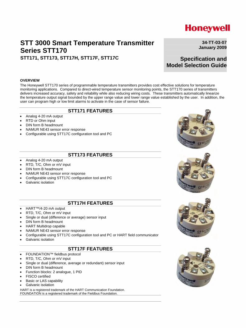
Wiring
STT171
STT173 Input:
RTD, 2-wire RTD, 3-wire RTD, 4-wire TC, internal CJC
mV Resistance, 2-wire Resistance, 3-wire
Resistance, 4-wire
2-wire installation
TC, external CJC
Output:
Input:RTD, 2-wire RTD, 3-wire RTD, 4-wire TC, internal CJC
mV Resistance, 2-wire Resistance, 3-wire
Resistance, 4-wire
2-wire installation
TC, external CJC
Output:
RTD, 2-wire RTD, 3-wire Resistance, 3-wireResistance, 2-wire
2-wire installation
Output:
Input:
RTD, 2-wire RTD, 3-wire Resistance, 3-wireResistance, 2-wire
2-wire installation
Output:
Input:
34-TT-03-07 Page 3
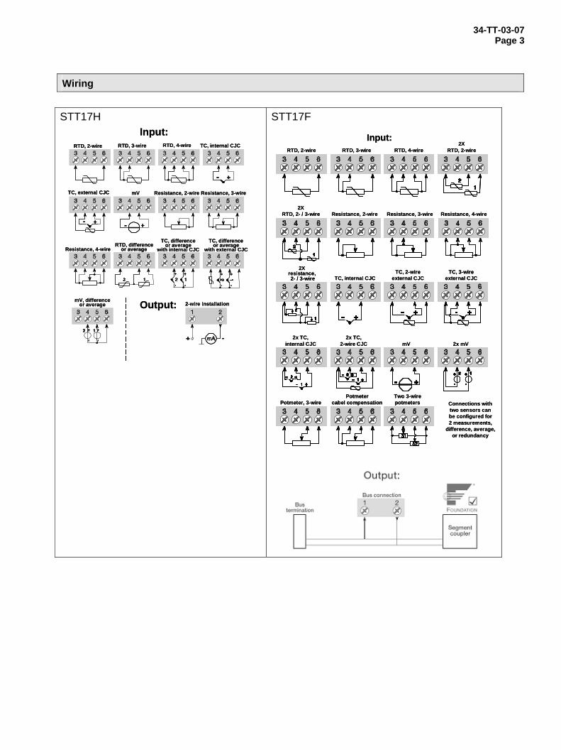
Wiring
STT17H
RTD, 2-wire
Resistance, 3-wire
RTD, 3-wire RTD, 4-wire TC, internal CJC
TC, external CJC mV Resistance, 2-wire
Resistance, 4-wireRTD, difference
or average
2-wire installation
TC, differenceor average
with internal CJCTC, difference
or averagewith external CJC
mV, differenceor average
Input:
Output:
STT17F
Input:RTD, 2-wire RTD, 3-wire RTD, 4-wire
2XRTD, 2-wire
2XRTD, 2- / 3-wire Resistance, 2-wire Resistance, 3-wire Resistance, 4-wire
2Xresistance,2- / 3-wire TC, internal CJC
TC, 2-wireexternal CJC
TC, 3-wireexternal CJC
2x TC,internal CJC
2x TC,2-wire CJC mV 2x mV
Potmeter, 3-wirePotmeter
cabel compensationTwo 3-wirepotmeters Connections with
two sensors canbe configured for2 measurements,
difference, average,or redundancy
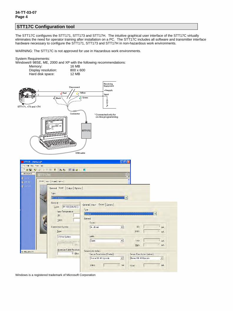
34-TT-03-07 Page 4 STT17C Configuration tool
The STT17C configures the STT171, STT173 and STT17H. The intuitive graphical user interface of the STT17C virtually eliminates the need for operator training after installation on a PC. The STT17C includes all software and transmitter interface hardware necessary to configure the STT171, STT173 and STT17H in non-hazardous work environments. WARNING: The STT17C is not approved for use in Hazardous work environments. System Requirements: Windows® 98SE, ME, 2000 and XP with the following recommendations: Memory: 16 MB Display resolution: 800 x 600 Hard disk space: 12 MB
Windows is a registered trademark of Microsoft Corporation
34-TT-03-07 Page 5
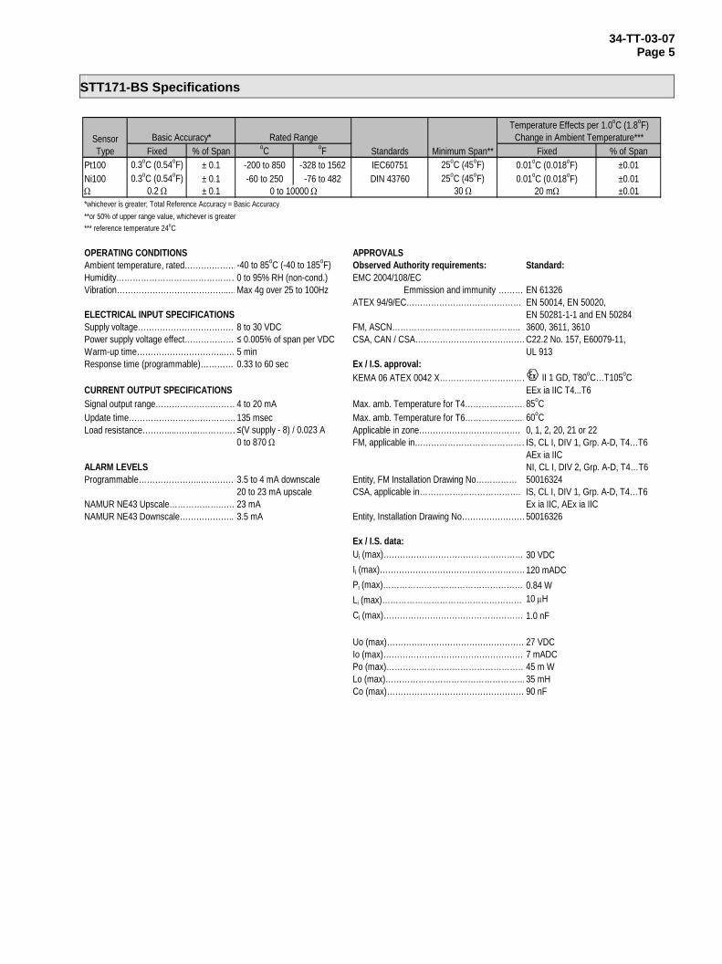
STT171-BS Specifications
Fixed % of Span oC oF % of SpanPt100 0.3oC (0.54oF) ± 0.1 -200 to 850 -328 to 1562 IEC60751 25oC (45oF) ±0.01Ni100 0.3oC (0.54oF) ± 0.1 -60 to 250 -76 to 482 DIN 43760 25oC (45oF) ±0.01Ω 0.2 Ω ± 0.1 30 Ω ±0.01*whichever is greater; Total Reference Accuracy = Basic Accuracy**or 50% of upper range value, whichever is greater*** reference temperature 24oC
OPERATING CONDITIONS APPROVALSAmbient temperature, rated……….………-40 to 85oC (-40 to 185oF) Observed Authority requirements: Standard:Humidity………………………………………0 to 95% RH (non-cond.) EMC 2004/108/ECVibration…………………………………...…Max 4g over 25 to 100Hz Emmission and immunity ……… EN 61326
ATEX 94/9/EC…………………………………… EN 50014, EN 50020,ELECTRICAL INPUT SPECIFICATIONS EN 50281-1-1 and EN 50284Supply voltage………………………………8 to 30 VDC FM, ASCN……………………………………….. 3600, 3611, 3610Power supply voltage effect……………….≤ 0.005% of span per VDC CSA, CAN / CSA…………………………………. C22.2 No. 157, E60079-11, Warm-up time…………………………..…. 5 min UL 913Response time (programmable)……………0.33 to 60 sec Ex / I.S. approval:
KEMA 06 ATEX 0042 X…………………………… II 1 GD, T80oC…T105oCCURRENT OUTPUT SPECIFICATIONS EEx ia IIC T4...T6Signal output range…………………………4 to 20 mA Max. amb. Temperature for T4……………………85oCUpdate time…………………………………135 msec Max. amb. Temperature for T6……………………60oCLoad resistance………....……...……………≤(V supply - 8) / 0.023 A Applicable in zone………………………………. 0, 1, 2, 20, 21 or 22
0 to 870 Ω FM, applicable in……………………………………IS, CL I, DIV 1, Grp. A-D, T4…T6AEx ia IIC
ALARM LEVELS NI, CL I, DIV 2, Grp. A-D, T4…T6Programmable…………………..……………3.5 to 4 mA downscale Entity, FM Installation Drawing No…………… 50016324
20 to 23 mA upscale CSA, applicable in………………………………. IS, CL I, DIV 1, Grp. A-D, T4…T6NAMUR NE43 Upscale……………….……23 mA Ex ia IIC, AEx ia IICNAMUR NE43 Downscale………………..…3.5 mA Entity, Installation Drawing No……………………50016326
Ex / I.S. data:Ui (max)…………………………………………… 30 VDCIi (max)………………………………………………120 mADCPi (max)………………………………………………0.84 WLi (max)…………………………………………… 10 μHCi (max)…………………………………………… 1.0 nF
Uo (max)……………………………………………27 VDCIo (max)…………………………………………… 7 mADCPo (max)……………………………………………45 m WLo (max)……………………………………………35 mHCo (max)……………………………………………90 nF
0 to 10000 Ω
Minimum Span**Rated Range
20 mΩ
Fixed0.01oC (0.018oF)0.01oC (0.018oF)
Standards
Temperature Effects per 1.0oC (1.8oF)Change in Ambient Temperature***Sensor
TypeBasic Accuracy*
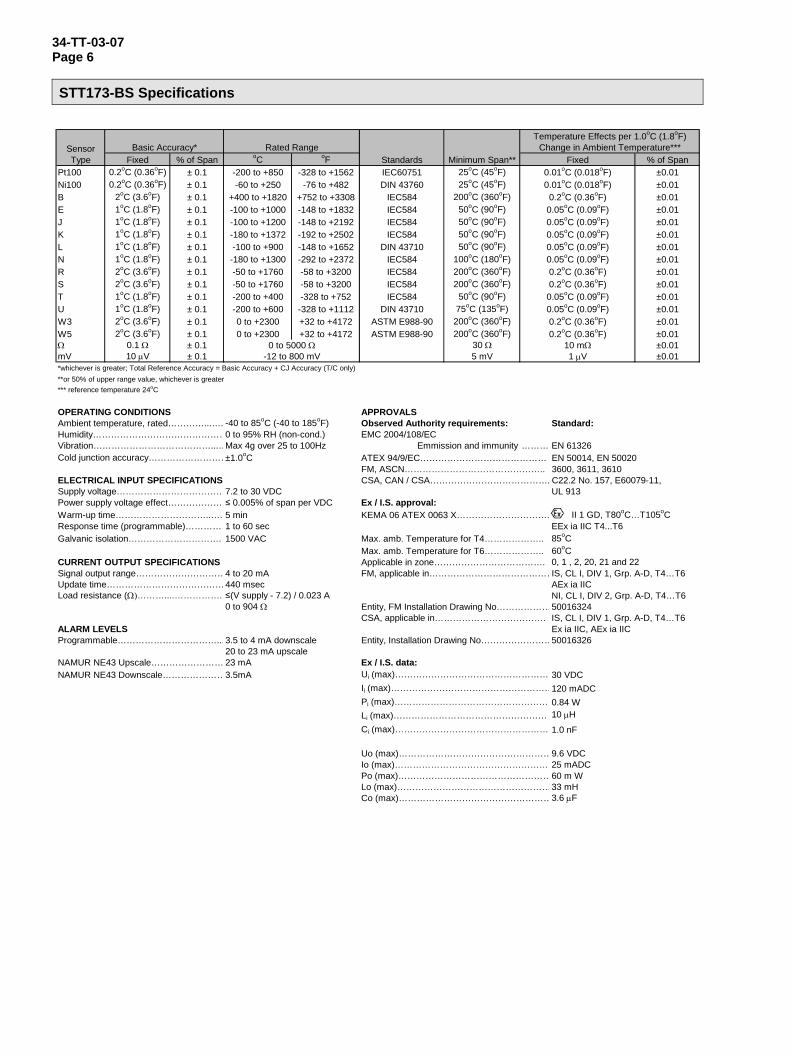
34-TT-03-07 Page 6 STT173-BS Specifications
Fixed % of Span oC oF % of SpanPt100 0.2oC (0.36oF) ± 0.1 -200 to +850 -328 to +1562 IEC60751 25oC (45oF) ±0.01Ni100 0.2oC (0.36oF) ± 0.1 -60 to +250 -76 to +482 DIN 43760 25oC (45oF) ±0.01B 2oC (3.6oF) ± 0.1 +400 to +1820 +752 to +3308 IEC584 200oC (360oF) ±0.01E 1oC (1.8oF) ± 0.1 -100 to +1000 -148 to +1832 IEC584 50oC (90oF) ±0.01J 1oC (1.8oF) ± 0.1 -100 to +1200 -148 to +2192 IEC584 50oC (90oF) ±0.01K 1oC (1.8oF) ± 0.1 -180 to +1372 -192 to +2502 IEC584 50oC (90oF) ±0.01L 1oC (1.8oF) ± 0.1 -100 to +900 -148 to +1652 DIN 43710 50oC (90oF) ±0.01N 1oC (1.8oF) ± 0.1 -180 to +1300 -292 to +2372 IEC584 100oC (180oF) ±0.01R 2oC (3.6oF) ± 0.1 -50 to +1760 -58 to +3200 IEC584 200oC (360oF) ±0.01S 2oC (3.6oF) ± 0.1 -50 to +1760 -58 to +3200 IEC584 200oC (360oF) ±0.01T 1oC (1.8oF) ± 0.1 -200 to +400 -328 to +752 IEC584 50oC (90oF) ±0.01U 1oC (1.8oF) ± 0.1 -200 to +600 -328 to +1112 DIN 43710 75oC (135oF) ±0.01W3 2oC (3.6oF) ± 0.1 0 to +2300 +32 to +4172 ASTM E988-90 200oC (360oF) ±0.01W5 2oC (3.6oF) ± 0.1 0 to +2300 +32 to +4172 ASTM E988-90 200oC (360oF) ±0.01Ω 0.1 Ω ± 0.1 30 Ω ±0.01mV 10 μV ± 0.1 5 mV ±0.01*whichever is greater; Total Reference Accuracy = Basic Accuracy + CJ Accuracy (T/C only)**or 50% of upper range value, whichever is greater*** reference temperature 24oC
OPERATING CONDITIONS APPROVALSAmbient temperature, rated…………...…. -40 to 85oC (-40 to 185oF) Observed Authority requirements: Standard:Humidity………………………………………0 to 95% RH (non-cond.) EMC 2004/108/ECVibration…………………………………...…Max 4g over 25 to 100Hz Emmission and immunity ……… EN 61326Cold junction accuracy………………………±1.0oC ATEX 94/9/EC…………………………………… EN 50014, EN 50020
FM, ASCN……………………………………….. 3600, 3611, 3610ELECTRICAL INPUT SPECIFICATIONS CSA, CAN / CSA…………………………………. C22.2 No. 157, E60079-11, Supply voltage………………………………7.2 to 30 VDC UL 913Power supply voltage effect……………….≤ 0.005% of span per VDC Ex / I.S. approval:Warm-up time…………………………..…. 5 min KEMA 06 ATEX 0063 X…………………………. II 1 GD, T80oC…T105oCResponse time (programmable)……………1 to 60 sec EEx ia IIC T4...T6Galvanic isolation…………………………. 1500 VAC Max. amb. Temperature for T4……………….. 85oC
Max. amb. Temperature for T6……………….. 60oCCURRENT OUTPUT SPECIFICATIONS Applicable in zone………………………………. 0, 1 , 2, 20, 21 and 22Signal output range…………………………4 to 20 mA FM, applicable in……………………………………IS, CL I, DIV 1, Grp. A-D, T4…T6Update time…………………………………440 msec AEx ia IICLoad resistance (Ω)………....……………. ≤(V supply - 7.2) / 0.023 A NI, CL I, DIV 2, Grp. A-D, T4…T6
0 to 904 Ω Entity, FM Installation Drawing No………………50016324CSA, applicable in………………………………. IS, CL I, DIV 1, Grp. A-D, T4…T6
ALARM LEVELS Ex ia IIC, AEx ia IICProgrammable……………………………...3.5 to 4 mA downscale Entity, Installation Drawing No……………………50016326
20 to 23 mA upscaleNAMUR NE43 Upscale…………………… 23 mA Ex / I.S. data:NAMUR NE43 Downscale…………………3.5mA Ui (max)…………………………………………… 30 VDC
Ii (max)………………………………………………120 mADCPi (max)………………………………………………0.84 WLi (max)…………………………………………… 10 μHCi (max)…………………………………………… 1.0 nF
Uo (max)……………………………………………9.6 VDCIo (max)…………………………………………… 25 mADCPo (max)……………………………………………60 m WLo (max)……………………………………………33 mHCo (max)……………………………………………3.6 μF
10 mΩ1 μV
0.05oC (0.09oF)0.05oC (0.09oF)0.2oC (0.36oF)0.2oC (0.36oF)
0.05oC (0.09oF)0.05oC (0.09oF)0.2oC (0.36oF)0.2oC (0.36oF)
0.2oC (0.36oF)0.05oC (0.09oF)0.05oC (0.09oF)0.05oC (0.09oF)
Fixed0.01oC (0.018oF)0.01oC (0.018oF)
Standards
Temperature Effects per 1.0oC (1.8oF)Change in Ambient Temperature***Sensor
TypeBasic Accuracy*
0 to 5000 Ω-12 to 800 mV
Minimum Span**Rated Range
34-TT-03-07 Page 7
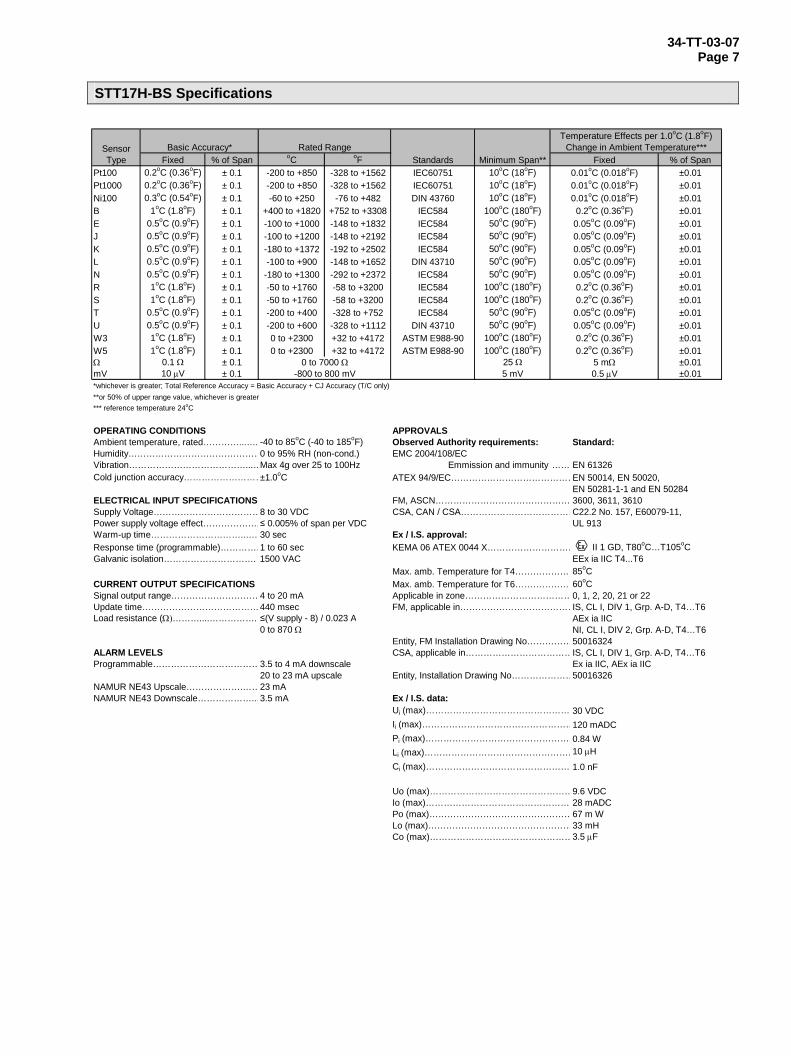
STT17H-BS Specifications
Fixed % of Span oC oF % of SpanPt100 0.2oC (0.36oF) ± 0.1 -200 to +850 -328 to +1562 IEC60751 10oC (18oF) ±0.01Pt1000 0.2oC (0.36oF) ± 0.1 -200 to +850 -328 to +1562 IEC60751 10oC (18oF) ±0.01Ni100 0.3oC (0.54oF) ± 0.1 -60 to +250 -76 to +482 DIN 43760 10oC (18oF) ±0.01B 1oC (1.8oF) ± 0.1 +400 to +1820 +752 to +3308 IEC584 100oC (180oF) ±0.01E 0.5oC (0.9oF) ± 0.1 -100 to +1000 -148 to +1832 IEC584 50oC (90oF) ±0.01J 0.5oC (0.9oF) ± 0.1 -100 to +1200 -148 to +2192 IEC584 50oC (90oF) ±0.01K 0.5oC (0.9oF) ± 0.1 -180 to +1372 -192 to +2502 IEC584 50oC (90oF) ±0.01L 0.5oC (0.9oF) ± 0.1 -100 to +900 -148 to +1652 DIN 43710 50oC (90oF) ±0.01N 0.5oC (0.9oF) ± 0.1 -180 to +1300 -292 to +2372 IEC584 50oC (90oF) ±0.01R 1oC (1.8oF) ± 0.1 -50 to +1760 -58 to +3200 IEC584 100oC (180oF) ±0.01S 1oC (1.8oF) ± 0.1 -50 to +1760 -58 to +3200 IEC584 100oC (180oF) ±0.01T 0.5oC (0.9oF) ± 0.1 -200 to +400 -328 to +752 IEC584 50oC (90oF) ±0.01U 0.5oC (0.9oF) ± 0.1 -200 to +600 -328 to +1112 DIN 43710 50oC (90oF) ±0.01W3 1oC (1.8oF) ± 0.1 0 to +2300 +32 to +4172 ASTM E988-90 100oC (180oF) ±0.01W5 1oC (1.8oF) ± 0.1 0 to +2300 +32 to +4172 ASTM E988-90 100oC (180oF) ±0.01Ω 0.1 Ω ± 0.1 25 Ω ±0.01mV 10 μV ± 0.1 5 mV ±0.01*whichever is greater; Total Reference Accuracy = Basic Accuracy + CJ Accuracy (T/C only)**or 50% of upper range value, whichever is greater*** reference temperature 24oC
OPERATING CONDITIONS APPROVALSAmbient temperature, rated…………...…. -40 to 85oC (-40 to 185oF) Observed Authority requirements: Standard:Humidity………………………………………0 to 95% RH (non-cond.) EMC 2004/108/ECVibration…………………………………...…Max 4g over 25 to 100Hz Emmission and immunity …… EN 61326Cold junction accuracy………………………±1.0oC ATEX 94/9/EC……………………………………EN 50014, EN 50020,
EN 50281-1-1 and EN 50284ELECTRICAL INPUT SPECIFICATIONS FM, ASCN……………………………………… 3600, 3611, 3610Supply Voltage………………………………8 to 30 VDC CSA, CAN / CSA…………………………………C22.2 No. 157, E60079-11, Power supply voltage effect……………….≤ 0.005% of span per VDC UL 913Warm-up time…………………………..…. 30 sec Ex / I.S. approval:Response time (programmable)……………1 to 60 sec KEMA 06 ATEX 0044 X………………………… II 1 GD, T80oC…T105oCGalvanic isolation…………………………. 1500 VAC EEx ia IIC T4...T6
Max. amb. Temperature for T4…………………85oCCURRENT OUTPUT SPECIFICATIONS Max. amb. Temperature for T6…………………60oCSignal output range…………………………4 to 20 mA Applicable in zone………………………………0, 1, 2, 20, 21 or 22Update time…………………………………440 msec FM, applicable in…………………………………IS, CL I, DIV 1, Grp. A-D, T4…T6Load resistance (Ω)………....……………. ≤(V supply - 8) / 0.023 A AEx ia IIC
0 to 870 Ω NI, CL I, DIV 2, Grp. A-D, T4…T6Entity, FM Installation Drawing No……………50016324
ALARM LEVELS CSA, applicable in………………………………IS, CL I, DIV 1, Grp. A-D, T4…T6Programmable………………………………3.5 to 4 mA downscale Ex ia IIC, AEx ia IIC
20 to 23 mA upscale Entity, Installation Drawing No…………………50016326NAMUR NE43 Upscale……………….……23 mANAMUR NE43 Downscale………………..…3.5 mA Ex / I.S. data:
Ui (max)………………………………………… 30 VDCIi (max)……………………………………………120 mADCPi (max)……………………………………………0.84 WLi (max)……………………………………………10 μHCi (max)………………………………………… 1.0 nF
Uo (max)…………………………………………9.6 VDCIo (max)………………………………………… 28 mADCPo (max)…………………………………………67 m WLo (max)…………………………………………33 mHCo (max)…………………………………………3.5 μF
0 to 7000 Ω-800 to 800 mV
Minimum Span**Rated Range
Fixed0.01oC (0.018oF)
0.01oC (0.018oF)
Standards
Temperature Effects per 1.0oC (1.8oF)Change in Ambient Temperature***Sensor
TypeBasic Accuracy*
0.01oC (0.018oF)
0.2oC (0.36oF)0.05oC (0.09oF)0.05oC (0.09oF)0.05oC (0.09oF)0.05oC (0.09oF)0.05oC (0.09oF)0.2oC (0.36oF)0.2oC (0.36oF)
5 mΩ0.5 μV
0.05oC (0.09oF)0.05oC (0.09oF)0.2oC (0.36oF)0.2oC (0.36oF)
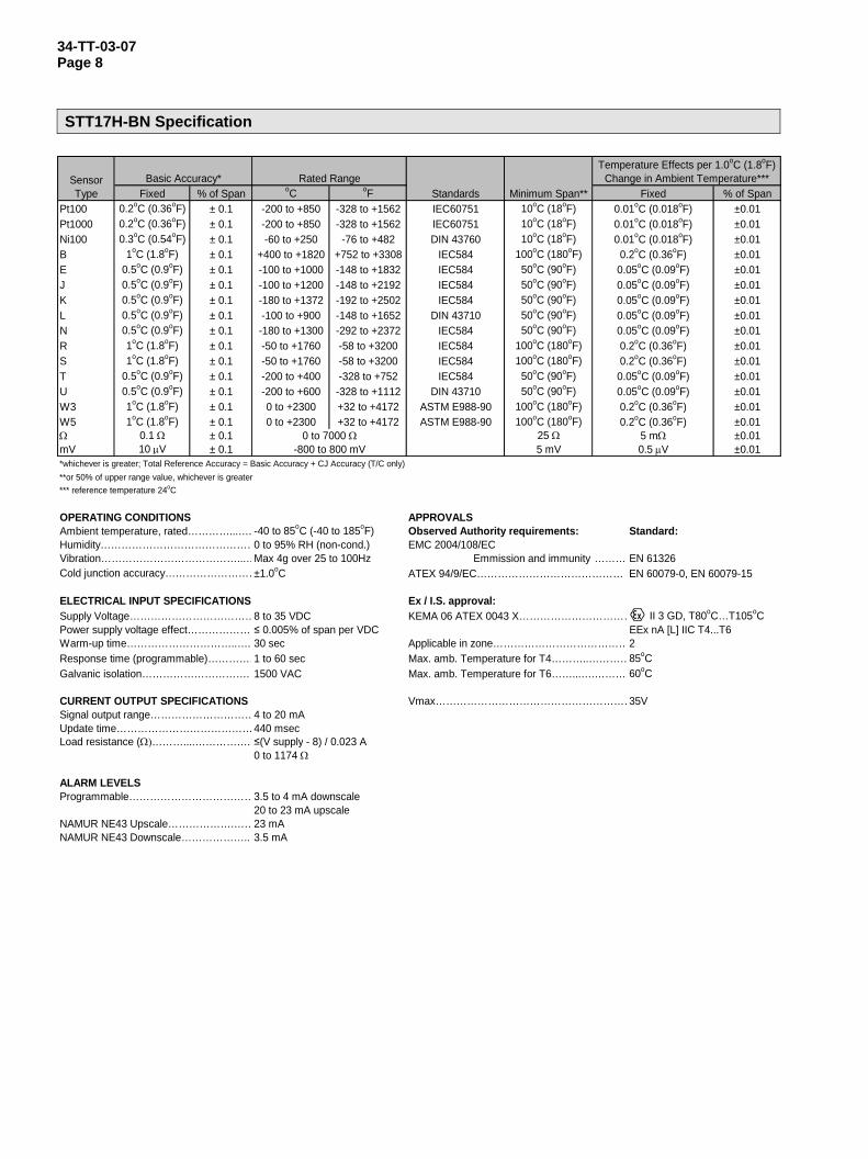
34-TT-03-07 Page 8 STT17H-BN Specification
Fixed % of Span oC oF % of SpanPt100 0.2oC (0.36oF) ± 0.1 -200 to +850 -328 to +1562 IEC60751 10oC (18oF) ±0.01Pt1000 0.2oC (0.36oF) ± 0.1 -200 to +850 -328 to +1562 IEC60751 10oC (18oF) ±0.01Ni100 0.3oC (0.54oF) ± 0.1 -60 to +250 -76 to +482 DIN 43760 10oC (18oF) ±0.01B 1oC (1.8oF) ± 0.1 +400 to +1820 +752 to +3308 IEC584 100oC (180oF) ±0.01E 0.5oC (0.9oF) ± 0.1 -100 to +1000 -148 to +1832 IEC584 50oC (90oF) ±0.01J 0.5oC (0.9oF) ± 0.1 -100 to +1200 -148 to +2192 IEC584 50oC (90oF) ±0.01K 0.5oC (0.9oF) ± 0.1 -180 to +1372 -192 to +2502 IEC584 50oC (90oF) ±0.01L 0.5oC (0.9oF) ± 0.1 -100 to +900 -148 to +1652 DIN 43710 50oC (90oF) ±0.01N 0.5oC (0.9oF) ± 0.1 -180 to +1300 -292 to +2372 IEC584 50oC (90oF) ±0.01R 1oC (1.8oF) ± 0.1 -50 to +1760 -58 to +3200 IEC584 100oC (180oF) ±0.01S 1oC (1.8oF) ± 0.1 -50 to +1760 -58 to +3200 IEC584 100oC (180oF) ±0.01T 0.5oC (0.9oF) ± 0.1 -200 to +400 -328 to +752 IEC584 50oC (90oF) ±0.01U 0.5oC (0.9oF) ± 0.1 -200 to +600 -328 to +1112 DIN 43710 50oC (90oF) ±0.01W3 1oC (1.8oF) ± 0.1 0 to +2300 +32 to +4172 ASTM E988-90 100oC (180oF) ±0.01W5 1oC (1.8oF) ± 0.1 0 to +2300 +32 to +4172 ASTM E988-90 100oC (180oF) ±0.01Ω 0.1 Ω ± 0.1 25 Ω ±0.01mV 10 μV ± 0.1 5 mV ±0.01*whichever is greater; Total Reference Accuracy = Basic Accuracy + CJ Accuracy (T/C only)**or 50% of upper range value, whichever is greater*** reference temperature 24oC
OPERATING CONDITIONS APPROVALSAmbient temperature, rated…………...…. -40 to 85oC (-40 to 185oF) Observed Authority requirements: Standard:Humidity………………………………………0 to 95% RH (non-cond.) EMC 2004/108/ECVibration…………………………………...…Max 4g over 25 to 100Hz Emmission and immunity ……… EN 61326Cold junction accuracy………………………±1.0oC ATEX 94/9/EC…………………………………… EN 60079-0, EN 60079-15
ELECTRICAL INPUT SPECIFICATIONS Ex / I.S. approval:Supply Voltage………………………………8 to 35 VDC KEMA 06 ATEX 0043 X…………………………… II 3 GD, T80oC…T105oCPower supply voltage effect……………….≤ 0.005% of span per VDC EEx nA [L] IIC T4...T6Warm-up time…………………………..…. 30 sec Applicable in zone…………………………………2 Response time (programmable)……………1 to 60 sec Max. amb. Temperature for T4………..…………85oCGalvanic isolation…………………………. 1500 VAC Max. amb. Temperature for T6……...….……… 60oC
CURRENT OUTPUT SPECIFICATIONS Vmax…………………………………………………35VSignal output range…………………………4 to 20 mAUpdate time…………………………………440 msecLoad resistance (Ω)………....……………. ≤(V supply - 8) / 0.023 A
0 to 1174 Ω
ALARM LEVELSProgrammable………………………………3.5 to 4 mA downscale
20 to 23 mA upscaleNAMUR NE43 Upscale……………….……23 mANAMUR NE43 Downscale………………..…3.5 mA
5 mΩ0.5 μV
0.05oC (0.09oF)0.05oC (0.09oF)0.2oC (0.36oF)0.2oC (0.36oF)
0.05oC (0.09oF)0.05oC (0.09oF)0.2oC (0.36oF)0.2oC (0.36oF)
0.2oC (0.36oF)0.05oC (0.09oF)0.05oC (0.09oF)0.05oC (0.09oF)
Fixed0.01oC (0.018oF)
0.01oC (0.018oF)
Standards
Temperature Effects per 1.0oC (1.8oF)Change in Ambient Temperature***Sensor
TypeBasic Accuracy*
0.01oC (0.018oF)
0 to 7000 Ω-800 to 800 mV
Minimum Span**Rated Range
34-TT-03-07 Page 9
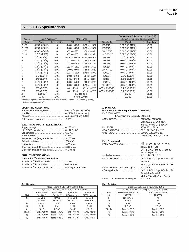
STT17F-BS Specifications
Fixed % of reading oC oF % of readingPt100 0.2oC (0.36oF) ± 0.1 -200 to +850 -328 to +1562 ±0.01Pt1000 0.2oC (0.36oF) ± 0.1 -200 to +850 -328 to +1562 ±0.01Ni100 0.3oC (0.54oF) ± 0.1 -60 to +250 -76 to +482 ±0.01Cu10 1.3oC (2.3oF) ± 0.1 -50 to +200 -58 to +392 ±0.01B 1oC (1.8oF) ± 0.1 +400 to +1820 +752 to +3308 ±0.01E 0.5oC (0.9oF) ± 0.1 -100 to +1000 -148 to +1832 ±0.01J 0.5oC (0.9oF) ± 0.1 -100 to +1200 -148 to +2192 ±0.01K 0.5oC (0.9oF) ± 0.1 -180 to +1372 -192 to +2502 ±0.01L 0.5oC (0.9oF) ± 0.1 -200 to +900 -328 to +1652 ±0.01N 0.5oC (0.9oF) ± 0.1 -180 to +1300 -292 to +2372 ±0.01R 1oC (1.8oF) ± 0.1 -50 to +1760 -58 to +3200 ±0.01S 1oC (1.8oF) ± 0.1 -50 to +1760 -58 to +3200 ±0.01T 0.5oC (0.9oF) ± 0.1 -200 to +400 -328 to +752 ±0.01U 0.5oC (0.9oF) ± 0.1 -200 to +600 -328 to +1112 ±0.01W3 1oC (1.8oF) ± 0.1 0 to +2300 +32 to +4172 ±0.01W5 1oC (1.8oF) ± 0.1 0 to +2300 +32 to +4172 ±0.01Ω 0.05 Ω ± 0.1 ±0.01mV 10 μV ± 0.1 ±0.01*whichever is greater; Total Reference Accuracy = Basic Accuracy + CJ Accuracy (T/C only)** reference temperature 24oC
OPERATING CONDITIONS APPROVALSAmbient temperature, rated…………...………-40 to 85oC (-40 to 185oF) Observed Authority requirements: Standard:Humidity…………………………………………0 to 95% RH (non-cond.) EMC 2004/108/ECVibration…………………………………...……Max 4g over 25 to 100Hz Emmission and immunity EN 61326Cold junction accuracy………......……………±0.5oC ATEX 94/9/EC……………………………EN 50014, EN 50020,
EN 50281-1-1, EN 50284,ELECTRICAL INPUT SPECIFICATIONS and IEC 60079-27 (FISCO)Supply Voltage…………………………………9 to 30 VDC FM, ASCN…………………………………3600, 3611, 3610
In FISCO installations………………………9 to 17.5 VDC CSA, CAN / CSA…………………………C22.2 No. 142, No. 157Consumption……………………………………< 11 mA CAN / CSA…………………………………E60079-0, E60079-11,Warm-up time…………………………..………30 sec E60079-15, UL913, UL1604Response time (programmable)………………1 to 60 secGalvanic isolation………………………………1500 VAC Ex / I.S. approval:Update time………………………………….. < 400 msec KEMA 06 ATEX 0046……………..…… II 1 GD, T65oC…T105oCExecution time, PID controller……………….< 200 msec EEx ia IIC T4…T6Execution time, analogue input………………< 50 msec Ex II 2(1) GD, T65oC…T105oC
EEx ib [ia] IIC T4…T6OUTPUT SPECIFICATIONS Applicable in zone…………………………0, 1, 2, 20, 21 or 22FoundationTM Fieldbus connection: FM, applicable in…………………………IS, CL I, DIV 1, Grp. A-D, T4…T6FoundationTM Fieldbus version…………….. ITK 4.6 AEx ia IICFoundationTM F. capability……………………Basic or LAS NI, CL I, DIV 2, Grp. A-D, T4…T6FoundationTM F. function blocks……………. 2 analogue and 1 PID Entity, FM Installation Drawing No………50016325
CSA, applicable in……………………… IS, CL I, DIV 1, Grp. A-D, T4…T6Ex ia IIC, AEx ia IICCL I, DIV 2, Grp. A-D, T4…T6
Entity, CSA Installation Drawing No……50016325
Ex / I.S. data: Ex / I.S. data:
Barrier where Barrier where Suitable for Suitable for UnitUnit Po < 0.84 W Po < 1.3 W FISCO systems FISCO systems UiUi 30 VDC 30 VDC 17.5 VDC 15 VDC IiIi 120 mADC 300 mADC 250 mADC 900 mADC PiPi 0.84 W 1.3 W 2.0 W 5.32 W LiLi 1 μH 1 μH 1 μH 1 μH CiCi 2.0 nF 2.0 nF 2.0 nF 2.0 nF T1…T4
T1…T4 Tamb. < 85oC Tamb. < 75oC Tamb. < 85oC Tamb. < 85oC T5T5 Tamb. < 70oC Tamb. < 65oC Tamb. < 60oC Tamb. < 60oC T6T6 Tamb. < 60oC Tamb. < 45oC Tamb. < 45oC Tamb. < 45oC
0.2oC (0.36oF)2 mΩ0.2 μV
0.2oC (0.36oF)0.05oC (0.09oF)0.05oC (0.09oF)0.2oC (0.36oF)
ASTM E988-90
IEC584IEC584
DIN 43710IEC584IEC584IEC584IEC584
Change in Ambient Temperature**Fixed
DIN 43710ASTM E988-90
0.05oC (0.09oF)0.05oC (0.09oF)0.2oC (0.36oF)
0.05oC (0.09oF)0.05oC (0.09oF)0.05oC (0.09oF)
0.02oC (0.036oF)0.2oC (0.36oF)
Sensor Type
Basic Accuracy*
DIN 43760
0.01oC (0.018oF)0.01oC (0.018oF)0.01oC (0.018oF)
Temperature Effects per 1.0oC (1.8oF)
IEC584
Rated RangeStandardsIEC60751IEC60751
α = 0.00427IEC584
Class I, Zone 0, EEx ia IIC, Entity/FISCOIS, Class I, Division 1, Group A, B, C, D, Entity/FISCO
Class I, Zone 1, EEx ib IIC, Entity/FISCO
0 to 10000 Ω-800 to 800 mV
IS, Class I, Division 2, Group A, B, C, D, Entity/FISCOBarrier where Po < 5.32 W FISCO segment coupler
30 VDC 17.5 VDC250 mADC All
5.32 W All1 μH 1 μH
2.0 nFTamb. < 85oCTamb. < 75oCTamb. < 60oC
2.0 nFTamb. < 85oCTamb. < 75oCTamb. < 60oC
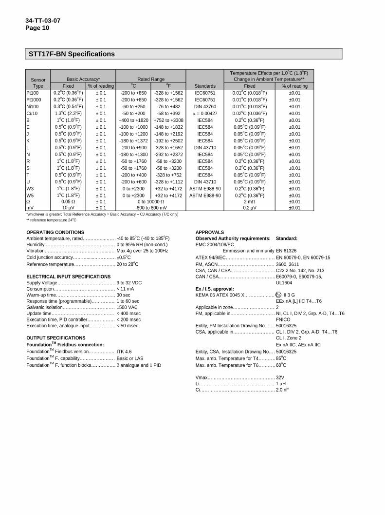
34-TT-03-07 Page 10 STT17F-BN Specifications
Fixed % of reading oC oF % of readingPt100 0.2oC (0.36oF) ± 0.1 -200 to +850 -328 to +1562 ±0.01Pt1000 0.2oC (0.36oF) ± 0.1 -200 to +850 -328 to +1562 ±0.01Ni100 0.3oC (0.54oF) ± 0.1 -60 to +250 -76 to +482 ±0.01Cu10 1.3oC (2.3oF) ± 0.1 -50 to +200 -58 to +392 ±0.01B 1oC (1.8oF) ± 0.1 +400 to +1820 +752 to +3308 ±0.01E 0.5oC (0.9oF) ± 0.1 -100 to +1000 -148 to +1832 ±0.01J 0.5oC (0.9oF) ± 0.1 -100 to +1200 -148 to +2192 ±0.01K 0.5oC (0.9oF) ± 0.1 -180 to +1372 -192 to +2502 ±0.01L 0.5oC (0.9oF) ± 0.1 -200 to +900 -328 to +1652 ±0.01N 0.5oC (0.9oF) ± 0.1 -180 to +1300 -292 to +2372 ±0.01R 1oC (1.8oF) ± 0.1 -50 to +1760 -58 to +3200 ±0.01S 1oC (1.8oF) ± 0.1 -50 to +1760 -58 to +3200 ±0.01T 0.5oC (0.9oF) ± 0.1 -200 to +400 -328 to +752 ±0.01U 0.5oC (0.9oF) ± 0.1 -200 to +600 -328 to +1112 ±0.01W3 1oC (1.8oF) ± 0.1 0 to +2300 +32 to +4172 ±0.01W5 1oC (1.8oF) ± 0.1 0 to +2300 +32 to +4172 ±0.01Ω 0.05 Ω ± 0.1 ±0.01mV 10 μV ± 0.1 ±0.01*whichever is greater; Total Reference Accuracy = Basic Accuracy + CJ Accuracy (T/C only)** reference temperature 24oC
OPERATING CONDITIONS APPROVALSAmbient temperature, rated…………...………-40 to 85oC (-40 to 185oF) Observed Authority requirements: Standard:Humidity…………………………………………0 to 95% RH (non-cond.) EMC 2004/108/ECVibration…………………………………...……Max 4g over 25 to 100Hz Emmission and immunity EN 61326Cold junction accuracy………......……………±0.5oC ATEX 94/9/EC……………………………EN 60079-0, EN 60079-15Reference temperature……………………… 20 to 28oC FM, ASCN…………………………………3600, 3611
CSA, CAN / CSA…………………………C22.2 No. 142, No. 213ELECTRICAL INPUT SPECIFICATIONS CAN / CSA…………………………………E60079-0, E60079-15,Supply Voltage…………………………………9 to 32 VDC UL1604Consumption……………………………………< 11 mA Ex / I.S. approval:Warm-up time…………………………..………30 sec KEMA 06 ATEX 0045 X……………..… II 3 GResponse time (programmable)………………1 to 60 sec EEx nA [L] IIC T4…T6Galvanic isolation………………………………1500 VAC Applicable in zone…………………………2Update time………………………………….. < 400 msec FM, applicable in…………………………NI, CL I, DIV 2, Grp. A-D, T4…T6Execution time, PID controller……………….< 200 msec FNICOExecution time, analogue input………………< 50 msec Entity, FM Installation Drawing No………50016325
CSA, applicable in……………………… CL I, DIV 2, Grp. A-D, T4…T6OUTPUT SPECIFICATIONS CL I, Zone 2,FoundationTM Fieldbus connection: Ex nA IIC, AEx nA IICFoundationTM Fieldbus version…………….. ITK 4.6 Entity, CSA, Installation Drawing No……50016325FoundationTM F. capability……………………Basic or LAS Max. amb. Temperature for T4…………85oCFoundationTM F. function blocks……………. 2 analogue and 1 PID Max. amb. Temperature for T6…………60oC
Vmax………………………………………32VLi……………………………………………1 μHCi……………………………………………2.0 nF
0.2 μV
0.05oC (0.09oF)0.2oC (0.36oF)0.2oC (0.36oF)
2 mΩ
0.02oC (0.036oF)0.2oC (0.36oF)
0.05oC (0.09oF)0.05oC (0.09oF)
0 to 10000 Ω-800 to 800 mV
Rated RangeStandardsIEC60751IEC60751DIN 43760
α = 0.00427IEC584IEC584
Sensor Type
Basic Accuracy*Temperature Effects per 1.0oC (1.8oF)
Change in Ambient Temperature**Fixed
0.01oC (0.018oF)0.01oC (0.018oF)0.01oC (0.018oF)
0.2oC (0.36oF)0.2oC (0.36oF)0.05oC (0.09oF)
IEC584IEC584
DIN 43710 0.05oC (0.09oF)0.05oC (0.09oF)
0.05oC (0.09oF)
IEC584IEC584IEC584IEC584
DIN 43710ASTM E988-90ASTM E988-90
34-TT-03-07 Page 11
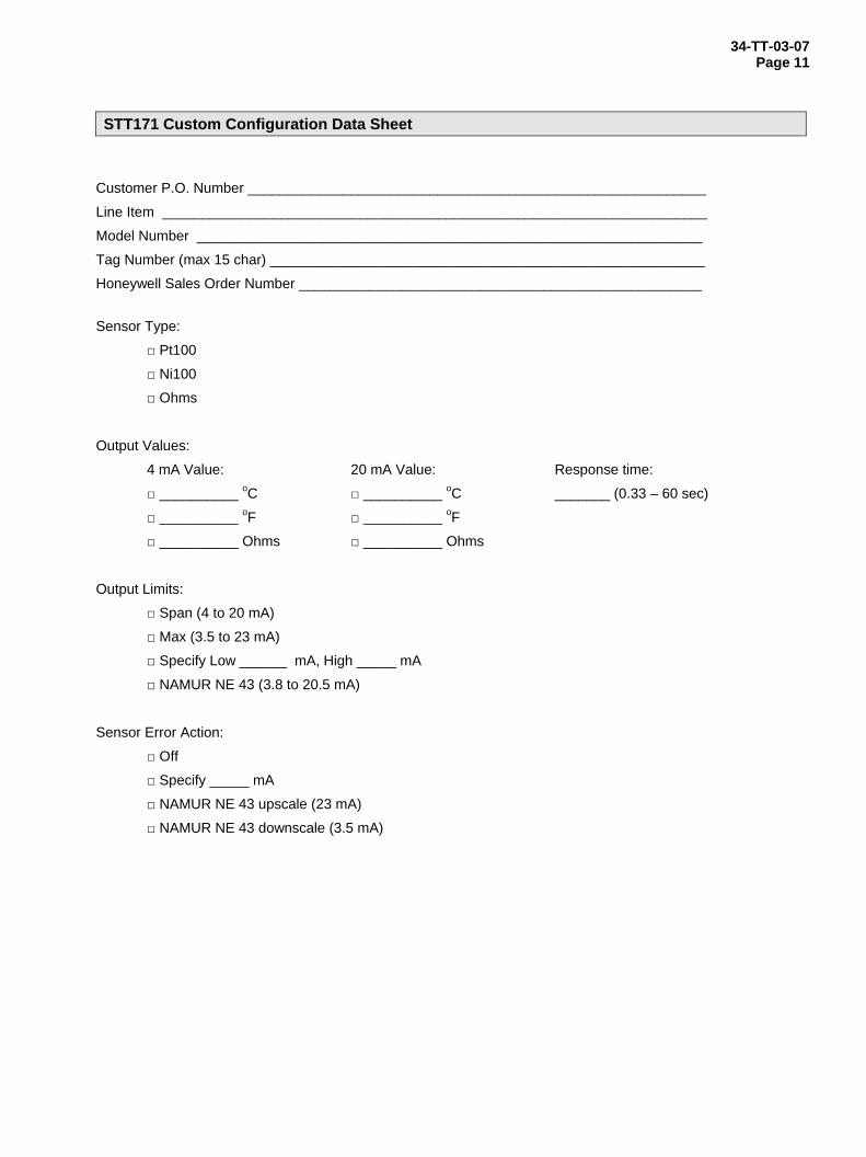
STT171 Custom Configuration Data Sheet
Customer P.O. Number __________________________________________________________
Line Item _____________________________________________________________________
Model Number ________________________________________________________________
Tag Number (max 15 char) _______________________________________________________
Honeywell Sales Order Number ___________________________________________________
Sensor Type:
□ Pt100
□ Ni100
□ Ohms
Output Values:
4 mA Value: 20 mA Value: Response time:
□ __________ oC □ __________ oC _______ (0.33 – 60 sec)
□ __________ oF □ __________ oF
□ __________ Ohms □ __________ Ohms
Output Limits:
□ Span (4 to 20 mA)
□ Max (3.5 to 23 mA)
□ Specify Low ______ mA, High _____ mA
□ NAMUR NE 43 (3.8 to 20.5 mA)
Sensor Error Action:
□ Off
□ Specify _____ mA
□ NAMUR NE 43 upscale (23 mA)
□ NAMUR NE 43 downscale (3.5 mA)
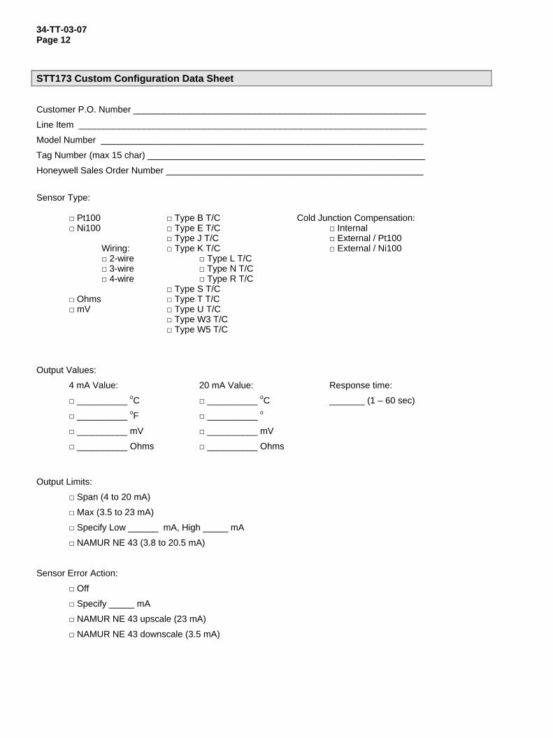
34-TT-03-07 Page 12
STT173 Custom Configuration Data Sheet Customer P.O. Number __________________________________________________________
Line Item _____________________________________________________________________
Model Number ________________________________________________________________
Tag Number (max 15 char) _______________________________________________________
Honeywell Sales Order Number ___________________________________________________
Sensor Type:
□ Pt100 □ Type B T/C Cold Junction Compensation: □ Ni100 □ Type E T/C □ Internal □ Type J T/C □ External / Pt100 Wiring: □ Type K T/C □ External / Ni100 □ 2-wire □ Type L T/C □ 3-wire □ Type N T/C □ 4-wire □ Type R T/C □ Type S T/C □ Ohms □ Type T T/C
□ mV □ Type U T/C □ Type W3 T/C
□ Type W5 T/C
Output Values:
4 mA Value: 20 mA Value: Response time:
□ __________ oC □ __________ oC _______ (1 – 60 sec)
□ __________ oF □ __________ o
□ __________ mV □ __________ mV
□ __________ Ohms □ __________ Ohms
Output Limits:
□ Span (4 to 20 mA)
□ Max (3.5 to 23 mA)
□ Specify Low ______ mA, High _____ mA
□ NAMUR NE 43 (3.8 to 20.5 mA)
Sensor Error Action:
□ Off
□ Specify _____ mA
□ NAMUR NE 43 upscale (23 mA)
□ NAMUR NE 43 downscale (3.5 mA)
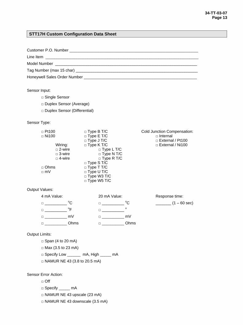
34-TT-03-07 Page 13
STT17H Custom Configuration Data Sheet Customer P.O. Number __________________________________________________________
Line Item _____________________________________________________________________
Model Number ________________________________________________________________
Tag Number (max 15 char) _______________________________________________________
Honeywell Sales Order Number ___________________________________________________
Sensor Input:
□ Single Sensor
□ Duplex Sensor (Average)
□ Duplex Sensor (Differential)
Sensor Type:
□ Pt100 □ Type B T/C Cold Junction Compensation: □ Ni100 □ Type E T/C □ Internal □ Type J T/C □ External / Pt100 Wiring: □ Type K T/C □ External / Ni100 □ 2-wire □ Type L T/C □ 3-wire □ Type N T/C □ 4-wire □ Type R T/C □ Type S T/C □ Ohms □ Type T T/C
□ mV □ Type U T/C □ Type W3 T/C
□ Type W5 T/C Output Values:
4 mA Value: 20 mA Value: Response time:
□ __________ oC □ __________ oC _______ (1 – 60 sec)
□ __________ oF □ __________ o
□ __________ mV □ __________ mV
□ __________ Ohms □ __________ Ohms
Output Limits:
□ Span (4 to 20 mA)
□ Max (3.5 to 23 mA)
□ Specify Low ______ mA, High _____ mA
□ NAMUR NE 43 (3.8 to 20.5 mA)
Sensor Error Action:
□ Off
□ Specify _____ mA
□ NAMUR NE 43 upscale (23 mA)
□ NAMUR NE 43 downscale (3.5 mA)
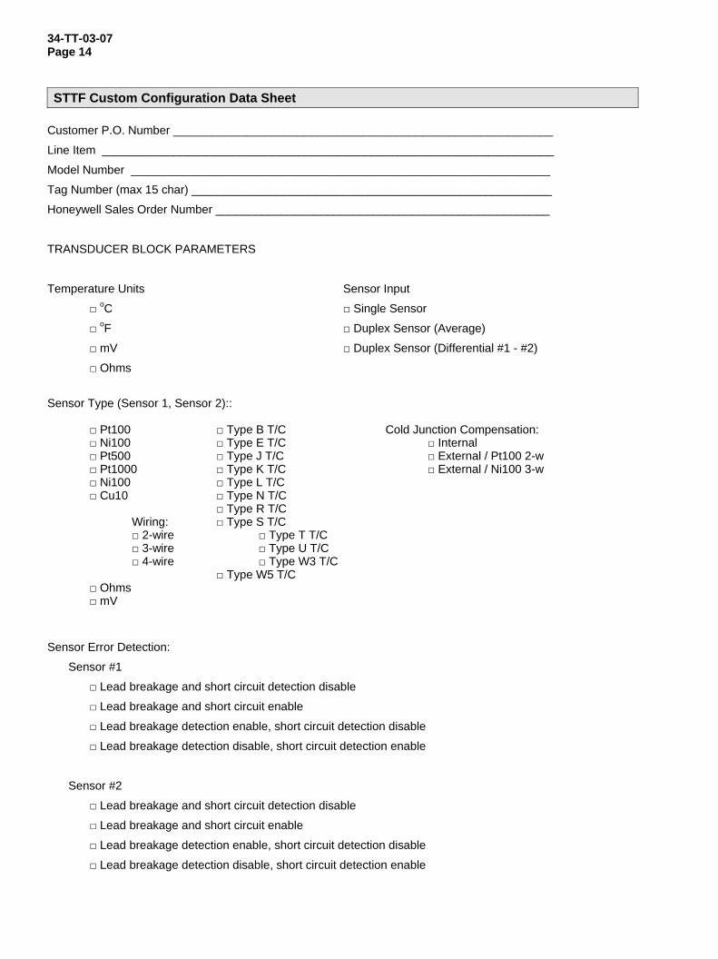
34-TT-03-07 Page 14 STTF Custom Configuration Data Sheet
Customer P.O. Number __________________________________________________________
Line Item _____________________________________________________________________
Model Number ________________________________________________________________
Tag Number (max 15 char) _______________________________________________________
Honeywell Sales Order Number ___________________________________________________
TRANSDUCER BLOCK PARAMETERS
Temperature Units Sensor Input
□ oC □ Single Sensor
□ oF □ Duplex Sensor (Average)
□ mV □ Duplex Sensor (Differential #1 - #2)
□ Ohms
Sensor Type (Sensor 1, Sensor 2)::
□ Pt100 □ Type B T/C Cold Junction Compensation: □ Ni100 □ Type E T/C □ Internal □ Pt500 □ Type J T/C □ External / Pt100 2-w □ Pt1000 □ Type K T/C □ External / Ni100 3-w □ Ni100 □ Type L T/C □ Cu10 □ Type N T/C □ Type R T/C Wiring: □ Type S T/C □ 2-wire □ Type T T/C
□ 3-wire □ Type U T/C □ 4-wire □ Type W3 T/C
□ Type W5 T/C □ Ohms □ mV
Sensor Error Detection:
Sensor #1
□ Lead breakage and short circuit detection disable
□ Lead breakage and short circuit enable
□ Lead breakage detection enable, short circuit detection disable
□ Lead breakage detection disable, short circuit detection enable
Sensor #2
□ Lead breakage and short circuit detection disable
□ Lead breakage and short circuit enable
□ Lead breakage detection enable, short circuit detection disable
□ Lead breakage detection disable, short circuit detection enable
34-TT-03-07 Page 15
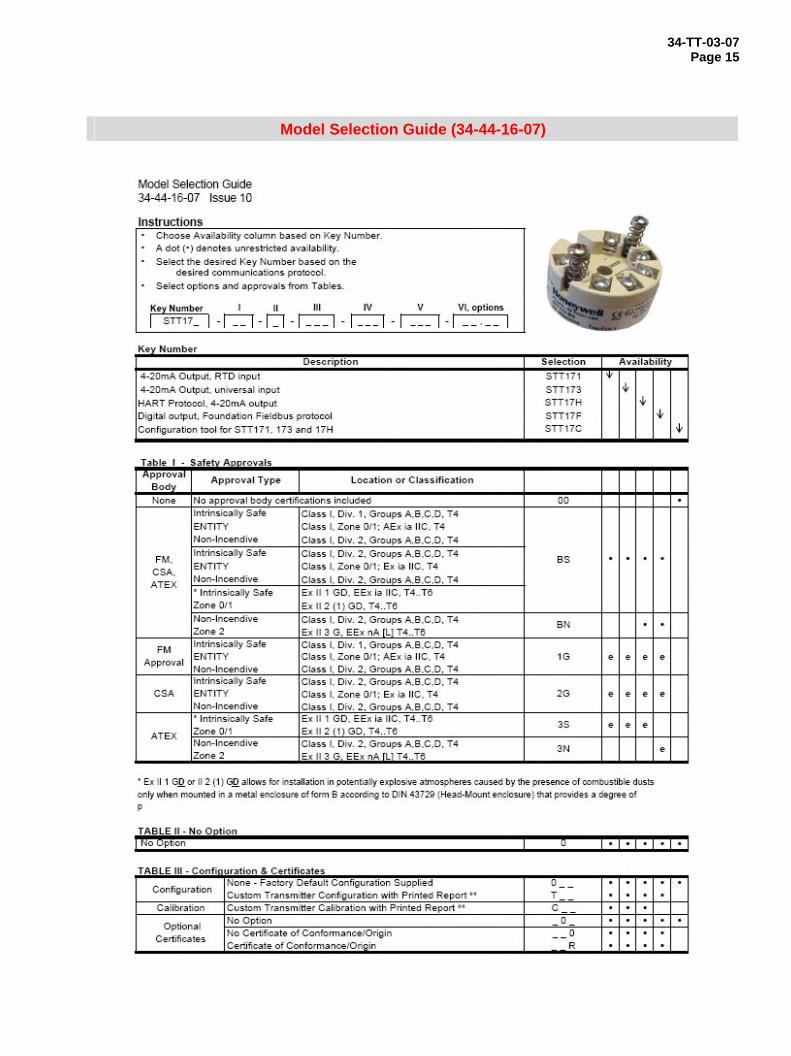
Model Selection Guide (34-44-16-07)
34-TT-03-07 Page 16
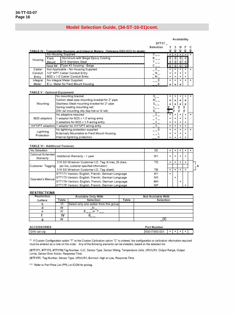
Model Selection Guide, (34-ST-16-01)cont.

34-TT-03-07 Page 17
This page has bee intentionally left blank
34-TT-03-07 Page 18
HART* is a trademark of the Hart Communication Foundation. FOUNDATION™ is a trademark of the Fieldbus Foundation.
Honeywell Process Solutions 2500 W. Union Hill Drive Phoenix, Arizona 85027 34-TT-03-07 Tel: 877.466.3993 or 602.313.6665 January 2009 www.honeywell.com/ps © 2009 Honeywell International Inc.