Embed Size (px)
Citation preview
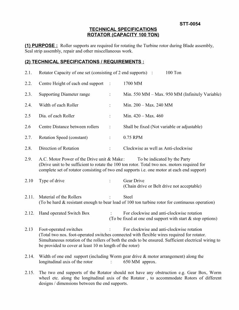
STT-0054TECHNICAL SPECIFICATIONS
ROTATOR (CAPACITY 100 TON)
(1) PURPOSE : Roller supports are required for rotating the Turbine rotor during Blade assembly, Seal strip assembly, repair and other miscellaneous work.
(2) TECHNICAL SPECIFICATIONS / REQUIREMENTS :
2.1. Rotator Capacity of one set (consisting of 2 end supports) : 100 Ton
2.2. Centre Height of each end support : 1700 MM
2.3. Supporting Diameter range : Min. 550 MM – Max. 950 MM (Infinitely Variable)
2.4. Width of each Roller : Min. 200 – Max. 240 MM
2.5 Dia. of each Roller : Min. 420 – Max. 460
2.6 Centre Distance between rollers : Shall be fixed (Not variable or adjustable)
2.7. Rotation Speed (constant) : 0.75 RPM
2.8. Direction of Rotation : Clockwise as well as Anti-clockwise
2.9. A.C. Motor Power of the Drive unit & Make : To be indicated by the Party (Drive unit to be sufficient to rotate the 100 ton rotor. Total two nos. motors required for complete set of rotator consisting of two end supports i.e. one motor at each end support)
2.10 Type of drive : Gear Drive (Chain drive or Belt drive not acceptable)
2.11. Material of the Rollers : Steel (To be hard & resistant enough to bear load of 100 ton turbine rotor for continuous operation)
2.12. Hand operated Switch Box : For clockwise and anti-clockwise rotation(To be fixed at one end support with start & stop options)
2.13 Foot-operated switches : For clockwise and anti-clockwise rotation(Total two nos. foot-operated switches connected with flexible wires required for rotator. Simultaneous rotation of the rollers of both the ends to be ensured. Sufficient electrical wiring to be provided to cover at least 10 m length of the rotor)
2.14. Width of one end support (including Worm gear drive & motor arrangement) along the longitudinal axis of the rotor : 650 MM approx.
2.15. The two end supports of the Rotator should not have any obstruction e.g. Gear Box, Worm wheel etc. along the longitudinal axis of the Rotator , to accommodate Rotors of different designs / dimensions between the end supports.

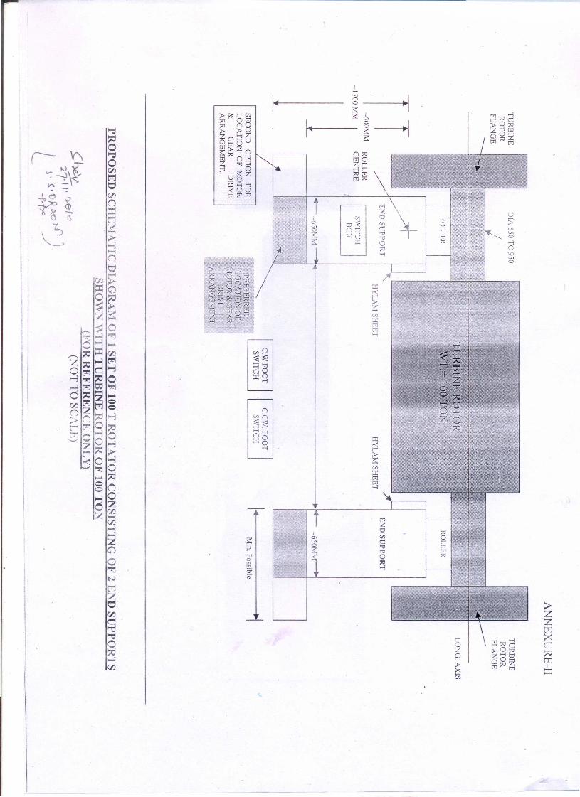
2.16 Motor arrangement is preferred to be located in the transverse direction on the outside only to avoid any fouling with the turbine rotors of different diameters. However, if the motor is located along the longitudinal axis then that has to be only on the outer side of the roller supports. Also it is to be ensured that approx. 300 mm clear vertical space from the top of the motor to the centre of the roller is required to avoid any fouling with the turbine rotor flanges which project on the outer side of the rollers. ( Ref: Annexure –I & II ).
2.17. Width of each end support along the longitudinal and transverse axis of rotator (including Worm gear drive & motor arrangement) should be kept as minimum possible to avoid undue coverage of the working area. Care should also be taken to facilitate easy movement of shop personnel around the rotator ( Ref: Annexure I & II ).
2.18. The Rotator set shall have drive units on both the end supports of the set. The Motors of both the end supports shall be interconnected for simultaneous start/stop on both ends. Only one motor is required for one end support of the rotator. Total two nos. motors required only for the complete set of rotator consisting of two end supports. The motor at one end support shall provide drive to one roller of that end support only. The other roller is free on axle. (Note : Schematic diagram enclosed for reference)
2.19 Inside surfaces of the flanges of the end supports to be fixed with softer material like Hylam etc. approx. 200x100x16 mm thick (2 nos. on each end support i.e. total 4 numbers for 1 rotator set) to avoid any damage to the turbine rotor surface.
2.20. Suitable lifting arrangement to be provided on the end supports for transportation. It should be possible to lift each support individually.
2.21. Detailed dimensional drawing (including arrangement of the drive unit) of rotator is to be submitted by the party at the time of submission of offer.
(3) POWER SUPPLY : AC 3-Phase, 415V + 10%/-15%, 50 Hz +/-3%.
(4) COLOUR : Colour of the Rotator shall be apple green.
(5) GUARANTEE : Supplier shall provide full and complete Guarantee for two yrs. trouble free operation after successful commissioning of the Equipment.
(6) PRE-DESPATCH INSPECTION : Pre-despatch inspection may be done by BHEL at supplier’s work to ensure specifications compliance and functioning of the rotators. This will be at the discretion of BHEL. The supplier to send their inspection report, before giving notice for pre-despatch inspection. The supplier to give prior notice sufficiently in advance for carrying out the pre-despatch inspection.
(7) MACHINE ACCEPTANCE : Final acceptance shall be made by BHEL at it’s plant following successful commissioning which shall include prove-out of the complete equipment for load testing. It shall be the responsibility of the supplier to arrange and provide all required electrical items alongwith the rotator. BHEL will provide power mains only. Any shortcoming in the functioning of the Rotator due to any reason shall be rectified by the supplier free of cost.

(8) MACHINE PACKING : The Rotator shall be packed rigidly to avoid any transit damage.
(9) QUALIFYING CONDITION : The supplier shall be Original Equipment Manufacturer and must have supplied at least two rotators of 100 T or more capacity with full contact details of the customers.
(10) SPARES (OPTIONAL): Recommended spares (if any) are required to be supplied alongwith the rotator.
NOTE : COST OF THE SPARES (IF ANY) TO BE QUOTED SEPARATELY.
(11) MANUAL: 5 Nos of operation and Maintenance (O&M) Manual to be supplied.