Embed Size (px)
Citation preview
State of North Carolina
Department of Transportation
Structures Management Unit
Manual
(1) PURPOSE: The Structures Management Unit Manual has been developed to
provide general guidance to Structures Management Unit personnel regarding
design policy and operating procedures. The objectives of this manual are to
promote efficiency in both design efforts and the transfer of information, as well
as to ensure uniformity in contract plan presentation.
(2) MANUAL CONTENT: This manual consists of the following two volumes:
Policy and Procedure Manual: This volume presents the policy and
procedure guidelines fundamental to the operation of the Structures
Management Unit. This volume contains procedures for the accurate
documentation and effective transmittal of information as required for the
sequential development of transportation projects.
Design Manual: This online volume illustrates standard office practice for
the implementation of design criteria and the preparation of transportation
structure plans and details.
(3) REFERENCE SYSTEM: A reference system within each volume is maintained
such that the chapter number precedes a section number. The text of each volume
is paginated per chapter at the bottom of the page. Figures, where applicable, are
presented separately and are referenced via similar designations.
(4) REVISIONS: This manual is designed as an active document. As new research,
products, and procedures evolve, such advances may be periodically incorporated
into the body of the manual. To maintain the manual’s integrity and continuity,
revisions should be immediately appended to the manual as they are distributed.
A master copy of this document, including all revisions, deletions, and additions
will be maintained by the Policy Development Group of the Structures
Management Unit.

PREFACE
DESIGN MANUAL
The Design Manual is one of two volumes of the Structures Management Unit Manual.
This manual has been developed for use by Structures Management Unit personnel and
other professionals for guidance in the design of transportation structures for the North
Carolina Department of Transportation. The primary objective of this volume is to
provide standard office practice regarding design, details, and notes, thereby enhancing
efficiency in the design effort and uniformity in the presentation of contract plans.
This manual accommodates both English and Metric (Système International) units. The
English units are considered primary while the Metric units are presented parenthetically
throughout the text. The English and Metric figures are available separately online. The
Metric figures are designated identically to the English figures. The English and Metric
figures are presented on the opposing faces of the same page. All plan notes contained in
the manual are accented with bold text, italicized, and indented from the body of the text.
The Design Manual is intended to be a technical manual, providing Engineers and
Technicians guidance in current design practice. This compilation of design practices
results primarily from experience in both contract plan development and the construction
of highway structures.
To preserve the autonomy of the Engineers and Technicians and encourage the
application of new ideas and technology, this manual does not attempt to address all
possible scenarios that may arise in the design of highway structures. Indeed, it is
assumed that many of these guidelines will necessarily continue to evolve.
The users of this manual are encouraged to present ideas that may vary from those
contained herein. These suggestions will be considered and implemented as deemed
appropriate.
This manual does not attempt to reproduce information that is adequately addressed in
text books, design publications, or the AASHTO LRFD Bridge Design Specifications.
STRUCTURE DESIGN MANUAL CHAPTER 1
________________________________________________________________ PLAN PREPARATION
1–i
CONTENTS
Chapter 1 ........................................................................................................................................... 1–1
1.1 General .................................................................................................................................. 1–1
1.2 Plan Sheets ............................................................................................................................ 1–1
1.2.1 Sheet Size .................................................................................................................. 1–1
1.2.2 Drafting ..................................................................................................................... 1–1
1.3 Plan Assembly ...................................................................................................................... 1–2
1.3.1 Title Sheet ................................................................................................................. 1–2
1.3.2 Index Sheet................................................................................................................ 1–2
1.3.3 General Drawing ....................................................................................................... 1–2
1.3.4 Superstructure ........................................................................................................... 1–2
1.3.5 Substructure .............................................................................................................. 1–2
1.3.6 Culverts ..................................................................................................................... 1–3
1.3.7 Walls ......................................................................................................................... 1–3
1.3.7.1 Earth Retaining .......................................................................................... 1–3
1.3.7.2 Sound Barrier ............................................................................................. 1–3

STRUCTURE DESIGN MANUAL CHAPTER 1
________________________________________________________________ PLAN PREPARATION
1–1
CHAPTER 1
PLAN PREPARATION
1.1 GENERAL
Contract plans are engineering drawings from which the project will be constructed. The
plans should contain all information necessary for Contractors to submit sound bids and to
construct the project. The plans should be concise without repetitious notes and details.
Engineers and Technicians should be thoroughly familiar with all the information presented
in this manual and its application to the plans. Whenever possible, use the Standard Design
Plans, Standard Drawings and details in the plans.
NCDOT uses MicroStation as its computer-aided drafting and design (CADD) software
package. CADD contract plans submitted to the Unit must use the same version of
MicroStation as the Department.
1.2 PLAN SHEETS
1.2.1 Sheet Size
The standard plan sheet size is 34 inches (864 mm) wide and 22 inches (559 mm) high.
Provide a 1½ inch (38 mm) binding margin from the left edge and a ½ inch (12 mm)
margin from the right, top and bottom edges.
To ensure legible prints, when final plan sheets are reduced in size, the minimum size
lettering shall be 1/8 inch (3.2 mm); see Figure 1-3 for details.
1.2.2 Drafting
Determine which details should be included in the plans and present them in a logically
grouped order. Avoid scattering details throughout the plans and overcrowding a sheet
with details and notes. Use standard line styles, line weights, lettering, reference notes, etc.,
to produce plans that are consistent from project to project.
Accuracy is an important element in preparing construction plans. Show dimensions in the
plans with the accuracy shown in Figure 1-2. The accuracy for items not listed in Figure
1-2 should be consistent with the figures shown in this manual. Avoid duplicate
dimensioning, but when necessary, ensure dimensions match in all details. Dimensions
should be compatible with connecting elements.
Designate skew angles as shown in Figure 1-5. Use Figures 1-6 through 1-10 when
computing bridge geometry and layout.
MicroStation allows the user to select multiple named levels for drafting. Adhere to the
basic line symbology shown in Figure 1-4. The line symbology is too extensive to list in
this figure. The complete line symbology and named levels are available via the
MicroStation workspace. Place information on the correct level names so the user is able to
STRUCTURE DESIGN MANUAL CHAPTER 1
________________________________________________________________ PLAN PREPARATION
1–2
see or print only the desired data by turning on or off the various level names. When
printing, ensure that the appropriate levels are turned on or off.
Provide a North arrow on the Title, Index (when necessary), and General Drawing sheets.
Provide a title block in the lower right-hand corner on each sheet, except the title sheet. The
information in the title block will vary depending on the sheet, but should generally reflect
information shown on the sheet. In the lower right-hand corner of the sheet, provide the
sequential sheet number and the total number of sheets for the project. For projects with
more than one structure, also provide the structure number just outside the margin, below
the title block.
1.3 PLAN ASSEMBLY
Assemble the structure plan sheets in the sequence shown in Figure 1-1.
1.3.1 Title Sheet
On the Title sheet, show the project information including project location, type of work,
vicinity map, project map, project length, and roadway / traffic design data on the title
sheet.
1.3.2 Index Sheet
Include an Index sheet in the plans when the project has 3 or more structures. Show the
project map on the sheet with a numerical designation for each structure. Provide a table
showing the station of each structure along the appropriate survey line, a structure
description, and the sheet numbers corresponding to the structure.
1.3.3 General Drawing
The General Drawing illustrates the basic layout of the structure in section view along the
survey line and in plan. See Chapter 5 for details.
1.3.4 Superstructure
The superstructure is the part of the bridge above, and including, the bridge bearings. The
plans should detail the girders, diaphragms, deck, barrier rails and sidewalks.
Superstructure sheets show the typical section through the superstructure, plan of the spans,
bridge framing plan and girder details. See Chapter 6 for detailed information.
1.3.5 Substructure
The substructure is the part of the bridge below the bridge bearings. The plans should
detail the end bent cap, bent cap, columns, piles, drilled piers, footings and footing piles.
On non-integral end bent bridges, the backwall and wingwalls shall be considered part of
the substructure. For bridges with integral end bents, include the portion of the abutment
and wingwalls above the construction joint in the superstructure plan sheets.
STRUCTURE DESIGN MANUAL CHAPTER 1
________________________________________________________________ PLAN PREPARATION
1–3
Substructure sheets show the layout of the end bents and bents in plan and elevation. See
Chapter 7 for detailed information.
1.3.6 Culverts
Culverts are structures typically used for short span stream crossings.
Culvert sheets show the culvert layout, plan and elevation views and a section through the
culvert barrel showing the reinforcing steel. Standard culvert wing walls are used whenever
possible. See Chapter 9 for detailed information.
1.3.7 Walls
Walls are typically designed to function as earth retaining structures or sound barriers.
1.3.7.1 Earth Retaining
The Roadway Design Unit establishes the location and limits of retaining walls. The
Geotechnical Engineering Unit recommends the earth retaining system which will be
employed and prepares the retaining wall plans. The plans typically show a plan view,
typical sections, details, notes and an elevation or profile view (wall envelope) of each wall.
Coordinate with the Geotechnical Engineering Unit to include retaining wall plans in the
structure plans, except when walls are the only structures on the project. In that case, the
Geotechnical Unit will coordinate with the Roadway Design Unit to include retaining wall
plans in the roadway plans.
1.3.7.2 Sound Barrier
The Roadway Design Unit establishes the location and limits of sound barrier walls. The
Structures Management Unit is responsible for preparing sound barrier wall plans. Use the
Sound Barrier Wall (SBW) standard drawings to prepare the plans. The Roadway Design
Unit will prepare the wall envelope, which is similar to that for retaining walls. The
Geotechnical Engineering Unit will provide sound barrier wall foundation
recommendations.
Coordinate with the Roadway Design and Geotechnical Engineering Units to include sound
barrier wall plans in the structure plans, except when walls are the only structures on the
project. In that case, coordinate with the Roadway Design Unit to include wall plans in the
roadway plans.
STRUCTURE DESIGN MANUAL CHAPTER 2 _____________________________________________________________________ DESIGN DATA
2–i
CONTENTS Chapter 2 ........................................................................................................................................... 2–1
2.1 Design Loads ........................................................................................................................ 2–1 2.1.1 General .......................................................................................................................2–1 2.1.2 Permanent Loads ........................................................................................................2–1
2.1.2.1 Dead Load .................................................................................................. 2–1 2.1.2.2 Lateral Earth Pressure ................................................................................ 2–2
2.1.3 Vehicular Live Load ..................................................................................................2–2 2.1.4 Earthquake Effects .....................................................................................................2–3 2.1.5 Friction on Bearings ...................................................................................................2–3 2.1.6 Temperature ...............................................................................................................2–3 2.1.7 Differential Settlement ...............................................................................................2–3 2.1.8 Torsion .......................................................................................................................2–4 2.1.9 Vessel Impact .............................................................................................................2–4
2.2 Material Design Properties ................................................................................................... 2–4 2.2.1 Steel............................................................................................................................2–4 2.2.2 Concrete .....................................................................................................................2–4 2.2.3 Elastomeric Bearings .................................................................................................2–4
2.3 Variations from and Interpretations of the AASHTO LRFD Specifications ........................ 2–5 2.3.1 Article 3.4.1 Load Factors and Load Combinations ..................................................2–5 2.3.2 Article 3.5.1 Dead Loads ...........................................................................................2–5 2.3.3 Article 3.6.4 Braking force ........................................................................................2–5 2.3.4 Article 3.6.5.1 Protection of Structures .....................................................................2–5 2.3.5 Article 4.6.2.2 Beam Slab Bridges.............................................................................2–5 2.3.6 Article 4.6.3 Methods of Analysis .............................................................................2–6 2.3.7 Article 5.7.3.4 Crack Control by Distribution of Reinforcement ..............................2–6 2.3.8 Article 5.9.4.1.2 Tension Stresses (Temporary Stresses before Losses) ...................2–6 2.3.9 Article 5.9.4.2.2 Tension Stresses (Stresses at Service III Limit State after
Losses) .......................................................................................................................2–6 2.3.10 Article 5.14.5.3 Design for Shear in Slabs of Box Culverts (Additional
Provisions for Culverts) .............................................................................................2–6 2.3.11 Article 6.6.1.3.1 Transverse Connection Plates .........................................................2–7 2.3.12 Article 6.10.1.7 Minimum Negative Flexure Concrete Deck Reinforcement ...........2–7 2.3.13 Article 6.13.2.3 Bolts, Nuts, and Washers .................................................................2–7 2.3.14 Article 9.7.2 Empirical Design ..................................................................................2–7 2.3.15 Article 10.7.1.2 Minimum Pile Spacing, Clearances, and Embedment into Cap ......2–7 2.3.16 Article 14.6.3.2 Moment (Force Effects Resulting from Restraint of Movement
at the Bearing) ............................................................................................................2–8 2.3.17 Article 14.7.5.2 Material Properties (Steel Reinforced Elastomeric Pads) ................2–8 2.3.18 Article 14.7.6.2 Material Properties (Elastomeric Pads) ...........................................2–8
2.4 Special Requirements............................................................................................................ 2–8 2.4.1 Non-Composite Permanent Load Deflections for Steel Bridges ...............................2–8

STRUCTURE DESIGN MANUAL CHAPTER 2 _____________________________________________________________________ DESIGN DATA
2–ii
2.4.2 Predicted Camber for Prestressed Concrete Girders, Cored Slabs, and Box Beams .........................................................................................................................2–9
STRUCTURE DESIGN MANUAL CHAPTER 2 _____________________________________________________________________ DESIGN DATA
2–1
CHAPTER 2
DESIGN DATA
2.1 DESIGN LOADS
2.1.1 General
Unless otherwise noted, design for load effects in accordance with the AASHTO LRFD Bridge Design Specifications. The LRFD specifications offer the minimum requirements, which apply to common highway bridges and other structures such as retaining walls and culverts. Unique structures, such as long-span bridges, may require design provisions in addition to those presented in the LRFD specifications. For variations from and interpretations of the LRFD specifications, See Section 2.3.
2.1.2 Permanent Loads
2.1.2.1 Dead Load
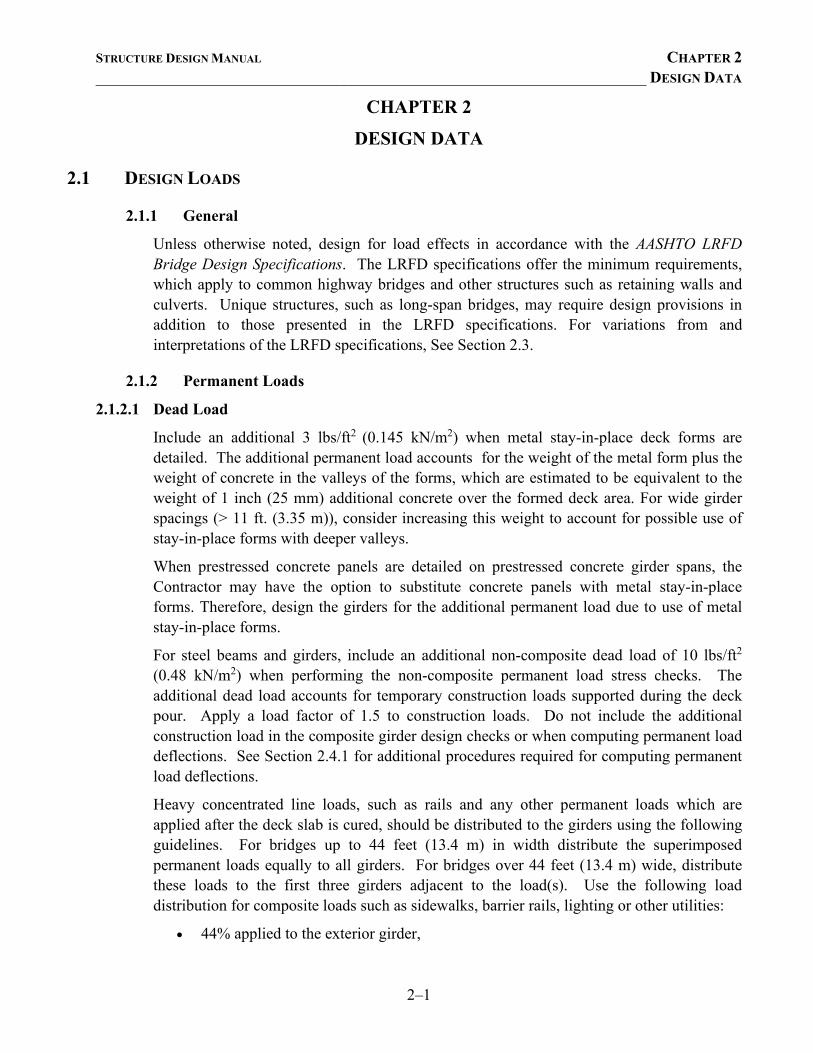
Include an additional 3 lbs/ft2 (0.145 kN/m2) when metal stay-in-place deck forms are detailed. The additional permanent load accounts for the weight of the metal form plus the weight of concrete in the valleys of the forms, which are estimated to be equivalent to the weight of 1 inch (25 mm) additional concrete over the formed deck area. For wide girder spacings (> 11 ft. (3.35 m)), consider increasing this weight to account for possible use of stay-in-place forms with deeper valleys.
When prestressed concrete panels are detailed on prestressed concrete girder spans, the Contractor may have the option to substitute concrete panels with metal stay-in-place forms. Therefore, design the girders for the additional permanent load due to use of metal stay-in-place forms.
For steel beams and girders, include an additional non-composite dead load of 10 lbs/ft2
(0.48 kN/m2) when performing the non-composite permanent load stress checks. The additional dead load accounts for temporary construction loads supported during the deck pour. Apply a load factor of 1.5 to construction loads. Do not include the additional construction load in the composite girder design checks or when computing permanent load deflections. See Section 2.4.1 for additional procedures required for computing permanent load deflections.
Heavy concentrated line loads, such as rails and any other permanent loads which are applied after the deck slab is cured, should be distributed to the girders using the following guidelines. For bridges up to 44 feet (13.4 m) in width distribute the superimposed permanent loads equally to all girders. For bridges over 44 feet (13.4 m) wide, distribute these loads to the first three girders adjacent to the load(s). Use the following load distribution for composite loads such as sidewalks, barrier rails, lighting or other utilities:
• 44% applied to the exterior girder,
STRUCTURE DESIGN MANUAL CHAPTER 2 _____________________________________________________________________ DESIGN DATA
2–2
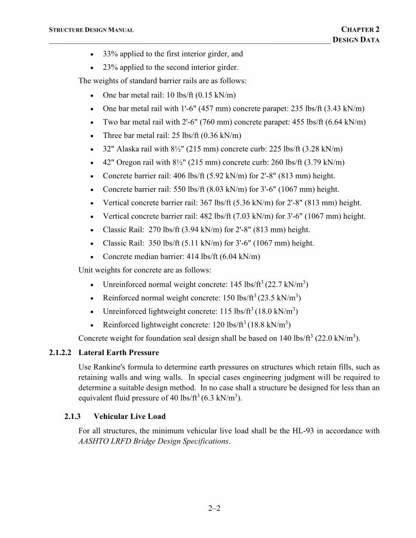
• 33% applied to the first interior girder, and • 23% applied to the second interior girder.
The weights of standard barrier rails are as follows:
• One bar metal rail: 10 lbs/ft (0.15 kN/m) • One bar metal rail with 1'-6" (457 mm) concrete parapet: 235 lbs/ft (3.43 kN/m) • Two bar metal rail with 2'-6" (760 mm) concrete parapet: 455 lbs/ft (6.64 kN/m) • Three bar metal rail: 25 lbs/ft (0.36 kN/m) • 32" Alaska rail with 8½" (215 mm) concrete curb: 225 lbs/ft (3.28 kN/m) • 42" Oregon rail with 8½" (215 mm) concrete curb: 260 lbs/ft (3.79 kN/m) • Concrete barrier rail: 406 lbs/ft (5.92 kN/m) for 2'-8" (813 mm) height. • Concrete barrier rail: 550 lbs/ft (8.03 kN/m) for 3'-6" (1067 mm) height. • Vertical concrete barrier rail: 367 lbs/ft (5.36 kN/m) for 2'-8" (813 mm) height. • Vertical concrete barrier rail: 482 lbs/ft (7.03 kN/m) for 3'-6" (1067 mm) height. • Classic Rail: 270 lbs/ft (3.94 kN/m) for 2'-8" (813 mm) height. • Classic Rail: 350 lbs/ft (5.11 kN/m) for 3'-6" (1067 mm) height. • Concrete median barrier: 414 lbs/ft (6.04 kN/m)
Unit weights for concrete are as follows:
• Unreinforced normal weight concrete: 145 lbs/ft3 (22.7 kN/m3) • Reinforced normal weight concrete: 150 lbs/ft3 (23.5 kN/m3) • Unreinforced lightweight concrete: 115 lbs/ft3 (18.0 kN/m3) • Reinforced lightweight concrete: 120 lbs/ft3 (18.8 kN/m3)
Concrete weight for foundation seal design shall be based on 140 lbs/ft3 (22.0 kN/m3).
2.1.2.2 Lateral Earth Pressure
Use Rankine's formula to determine earth pressures on structures which retain fills, such as retaining walls and wing walls. In special cases engineering judgment will be required to determine a suitable design method. In no case shall a structure be designed for less than an equivalent fluid pressure of 40 lbs/ft3 (6.3 kN/m3).
2.1.3 Vehicular Live Load
For all structures, the minimum vehicular live load shall be the HL-93 in accordance with AASHTO LRFD Bridge Design Specifications.
STRUCTURE DESIGN MANUAL CHAPTER 2 _____________________________________________________________________ DESIGN DATA
2–3
2.1.4 Earthquake Effects
Design all structures in accordance with the seismic requirements of the AASHTO LRFD Bridge Design Specifications. See Figure 2-1 for a generalized map of seismic performance zones in North Carolina. See Chapter 7 for additional information.
2.1.5 Friction on Bearings
The force effects caused by an expansion bearing sliding on its bearing plate on
the supporting substructure element must be included in the design of the
structure. These forces are determined by multiplying the coefficient of friction
by the total permanent load reaction on the bearing. For steel on steel, use a
coefficient of 0.30, and for stainless steel on teflon, use a coefficient of 0.10. For
elastomeric bearings, the force required to deform the elastomeric pad is found by
using the following equation:
Rubber) (Effective Thicknesse)Temperatur toDuen (Deflectio x Area)(Contact x Modulus)(Shear
=F
2.1.6 Temperature
Use the following temperature ranges when computing temperature force effects:
• Steel Structures: 10o F to 110o F (-12o C to 43o C)
• Concrete Structures: 20o F to 105o F (-7o C to 41o C)
The assumed normal fabrication and erection temperature is 60o F (16o C).
For expansion joints and bearings, use temperature ranges in accordance with Chapter 6. Consider using site specific temperature ranges, in accordance with the LRFD Specifications, to avoid detailing modular joints.
2.1.7 Differential Settlement
When differential settlement needs to be addressed by the Structures Management Unit, the Geotechnical Engineering Unit will convey the amount of differential settlement in the Foundation Recommendations. If no differential settlement is specified in the recommendations, then the potential for differential settlement has been discounted by the Geotechnical Engineering Unit in their foundation design.
Generally, the Geotechnical Engineering Unit will consider differential settlement in their foundation design if it is less than 1 inch (25 mm) over a period of time. If the differential settlement is greater than 1 inch (25 mm) over a period of time or if the structure is particularly sensitive to settlement, then the Structures Management Unit must consider the specified settlement in the substructure design.
STRUCTURE DESIGN MANUAL CHAPTER 2 _____________________________________________________________________ DESIGN DATA
2–4
2.1.8 Torsion
Where torsion effects are present, consider eliminating or mitigating torsion effects whenever possible. See Chapter 7 for guidance on mitigating eccentric loading on bent caps. Design members with torsion effects in accordance with LRFD Articles 5.8.2 and 5.8.3.6.
2.1.9 Vessel Impact
Design bridge components in navigable waterway crossings for vessel impact. Wherever possible, provide sufficient clearance to preclude vessel impact on the substructure.
2.2 MATERIAL DESIGN PROPERTIES
2.2.1 Steel
In general, use:
• Grade 50 weathering steel for girders and other structural members, • Grade 60 steel for reinforcing steel in concrete members. • Grade 270 steel for prestressing or post-tensioning tendons in concrete members.
See Chapter 6 for additional information on structural steel.
2.2.2 Concrete
For prestressed concrete members, specify the concrete strength required for design at release ( '
cif ) and 28 days ( 'cf ).
For concrete members with only reinforcing steel use the following design strengths:
• 4,000 psi when Class AA concrete is specified. • 3,000 psi when Class A concrete is specified.
2.2.3 Elastomeric Bearings
Design plain elastomeric pads using Method A in accordance with Article 14.7.6 of the LRFD specifications, and steel reinforced elastomeric pads using Method B in accordance with Article 14.7.5 of the LRFD specifications. Specify the shear modulus required for design; do not specify the durometer hardness. See Section 2.3.17 for additional information.
STRUCTURE DESIGN MANUAL CHAPTER 2 _____________________________________________________________________ DESIGN DATA
2–5
2.3 VARIATIONS FROM AND INTERPRETATIONS OF THE AASHTO LRFD SPECIFICATIONS
2.3.1 Article 3.4.1 Load Factors and Load Combinations
The variable γP reflects that the Strength and Extreme-Event limit state load factors for the various permanent loads are not single constants, but they can have two extreme values. Select the appropriate maximum or minimum permanent-load load factors to produce the more critical load effect.
For example, in continuous superstructures with relatively short-end spans, live load in the end span causes the bearing to be more compressed, while live load in the second span causes the bearing to be less compressed and can lead to uplift. To check the maximum compression force in the bearing, live load should be placed in the end span and the maximum DC dead load factor of 1.25 should be applied to the force effect(s). To check possible uplift of the bearing, live load should be placed in the second span and the minimum DC dead load factor of 0.90 should be applied to the force effect(s).
2.3.2 Article 3.5.1 Dead Loads
Include an additional 30 lbs/ft2 (1.4 kN/m2) for future bituminous wearing surface on all bridge floors, except those on movable spans. For movable spans and other unusual types of spans, use 8 lbs/ft2 (0.4 kN/m2) for future wearing surface. Do not include load due to future wearing surface in the camber calculations.
2.3.3 Article 3.6.4 Braking force
Compute the braking force, BR, as the greater of:
• 5% of the design truck plus lane load, • 5% of the design tandem plus lane load.
2.3.4 Article 3.6.5.1 Protection of Structures
Wherever possible, provide adequate clearance to avert design for vehicular collision and rail car collision with structures.
Abutments and piers located less than 30 ft. (9.14 m) from the edge of roadway shall be protected with a 2'-8" (813 mm) tall concrete barrier and approach guardrail in lieu of being designed for the equivalent static force of 400 kips. Abutments and Piers located less than 25'-0" (7.62 m) from the centerline of a railroad track must be protected by a crashwall. See Chapter 7 for guidance on pier protection.
2.3.5 Article 4.6.2.2 Beam Slab Bridges
Regardless of the method of analysis used, design the exterior beams and stringers to have at least as much factored resistance as interior beams.
STRUCTURE DESIGN MANUAL CHAPTER 2 _____________________________________________________________________ DESIGN DATA
2–6
The typical cross-section for cored slab and box beam bridges are to be considered type (g) as shown in Table 4.6.2.2.1-1 of the LRFD specifications. Compute moment and shear distribution factors as if the units are connected only enough to prevent relative vertical displacement at the interface, but not sufficiently to act as a unit.
2.3.6 Article 4.6.3 Methods of Analysis
The traditional AASHTO approach to bridge structural analysis employs distribution factors to account for distribution of wheel loads to the bridge girders. When a refined method of analysis is used, provide sufficient information on the bridge analysis to aid in future analyses for permit issuance and bridge rating. This information should include, but is not limited to a table of live load distribution factors for design force effects in each span
If the method of structural analysis employs transformed material section properties, provide tables of girder section properties (e.g. non-composite and composite) and structural resistances (e.g. flexural and shear). Also note any assumptions regarding boundary conditions.
2.3.7 Article 5.7.3.4 Crack Control by Distribution of Reinforcement
The de/6 criterion for maximum spacing of the skin reinforcement shall not apply to caps of end bents or multi-column piers with a depth of 4'-0" (1.22 m) or less.
2.3.8 Article 5.9.4.1.2 Tension Stresses (Temporary Stresses before Losses)
For girders, box beams, and cored slabs:
• In areas other than the precompressed tensile zone, the tensile stress limit shall be the lesser of 0.2 ksi (1.38 MPa) or '0948.0 cif (ksi) ( '25.0 cif (MPa)) at the ends of the member.
2.3.9 Article 5.9.4.2.2 Tension Stresses (Stresses at Service III Limit State after Losses)
Tension in the Precompressed Tensile Zone, Assuming Uncracked Sections:
• Box beams and cored slabs in non-corrosive and corrosive sites: 0 ksi (0 MPa) at mid span
• Girders and prestressed concrete deck panels in non-corrosive sites: '19.0 cf (ksi)
( '50.0 cf MPa).
• Girders in corrosive sites: 0 ksi (0 MPa) • Prestressed concrete deck panels in corrosive sites: 0 ksi (0 MPa)
2.3.10 Article 5.14.5.3 Design for Shear in Slabs of Box Culverts (Additional Provisions for Culverts)
The provisions of Article 5.14.5.3 apply to slabs of box culverts only; not walls.
STRUCTURE DESIGN MANUAL CHAPTER 2 _____________________________________________________________________ DESIGN DATA
2–7
2.3.11 Article 6.6.1.3.1 Transverse Connection Plates
For intermediate diaphragms on rolled beams used in simple spans, the vertical connector plate need not be welded or bolted to either the compression or tension flanges. Detail a 4 inch (100 mm) gap between both the top and bottom flanges and the vertical connector plate. See Figures 6-103, 6-104 and 6-105 for details.
2.3.12 Article 6.10.1.7 Minimum Negative Flexure Concrete Deck Reinforcement
Longitudinal reinforcing bars larger than #6 (#19) may be used to facilitate a favorable bar spacing.
2.3.13 Article 6.13.2.3 Bolts, Nuts, and Washers
All high strength bolts shall have a hardened washer in an outer ply, i.e. under the element turned in tightening.
Slotted holes in elements used to connect diaphragms need not have a structural plate washer or continuous bar that completely covers the slotted hole.
2.3.14 Article 9.7.2 Empirical Design
Empirical design of concrete decks shall not be permitted.
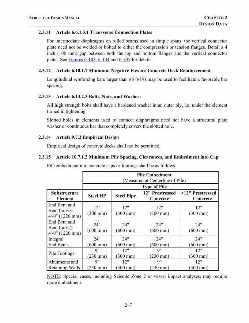
2.3.15 Article 10.7.1.2 Minimum Pile Spacing, Clearances, and Embedment into Cap
Pile embedment into concrete caps or footings shall be as follows:
Pile Embedment (Measured at Centerline of Pile)
Type of Pile Substructure
Element Steel HP Steel Pipe 12" Prestressed Concrete
>12" Prestressed Concrete
End Bent and Bent Caps < 4'-0" (1220 mm)
12" (300 mm)
12" (300 mm)
12" (300 mm)
12" (300 mm)
End Bent and Bent Caps ≥ 4'-0" (1220 mm)
24" (600 mm)
24" (600 mm)
24" (600 mm)
24" (600 mm)
Integral End Bents
24" (600 mm)
24" (600 mm)
24" (600 mm)
24" (600 mm)
Pile Footings 9" (230 mm)
12" (300 mm)
9" (230 mm)
12" (300 mm)
Abutments and Retaining Walls
9" (230 mm)
12" (300 mm)
9" (230 mm)
12" (300 mm)
NOTE: Special cases, including Seismic Zone 2 or vessel impact analyses, may require more embedment.
STRUCTURE DESIGN MANUAL CHAPTER 2 _____________________________________________________________________ DESIGN DATA
2–8
Center-to-center spacing for 12 inch (305 mm) prestressed concrete piles shall not be less than 2'-9" (840 mm) in footings.
2.3.16 Article 14.6.3.2 Moment (Force Effects Resulting from Restraint of Movement at the Bearing)
The moment transferred by elastomeric bearings need not be considered in the design of bridge substructures or superstructures.
2.3.17 Article 14.7.5.2 Material Properties (Steel Reinforced Elastomeric Pads)
For Method B, design steel reinforced elastomeric bearings for the specified shear modulus; i.e. without ±15% variation.
2.3.18 Article 14.7.6.2 Material Properties (Elastomeric Pads)
For Method A, assume the shear modulus is 0.110 ksi (0.76 MPa) for 50 durometer hardness and 0.160 ksi (1.10 MPa) for 60 durometer hardness.
2.4 SPECIAL REQUIREMENTS
2.4.1 Non-Composite Permanent Load Deflections for Steel Bridges
Non-composite permanent (i.e., dead load) deflections for steel bridges shall be computed in accordance with the North Carolina State University research report titled Development of a Simplified Procedure to Predict Dead Load Deflections of Skewed and Non-skewed Steel Plate Girders, 2006. This research recommends procedures for modifying non-composite dead load deflections based on a single girder line (SGL) analysis. These procedures are the Simplified procedure (SP), the Alternative Simplified procedure (ASP), and the Single Girder Line Straight Line (SGLSL) procedure. Use the appropriate procedures to modify the SGL predicted non-composite dead load deflections of steel bridges that meet all of the following criteria:
• Span Length ≤ 250 feet • Girder Spacing ≤ 11.5 feet
• 10.0Span
SpacingGirder ≤
Non-composite dead load deflections for bridges that do not meet the above criteria will require a more refined analysis that accounts for the stiffness of the entire structure, such as a 3-D finite element analysis.
A detailed summary of the development and application of the SP, ASP, and SGLSL procedures and an Excel spreadsheet that utilizes these procedures are available via the Differential Deflection link on the Structures Management Unit web page.
STRUCTURE DESIGN MANUAL CHAPTER 2 _____________________________________________________________________ DESIGN DATA
2–9
2.4.2 Predicted Camber for Prestressed Concrete Girders, Cored Slabs, and Box Beams
A research project titled Predicting Camber, Deflection, and Prestress Losses in Prestressed Concrete Members, 2011, was conducted to examine current and alternate methods for calculating prestress losses and camber of prestressed concrete members. Based on the results presented, the Refined Method, based on Article 5.9.5.4 of AASHTO LRFD Bridge Design Specifications, shall be used for determining camber in prestressed concrete members.
An Excel spreadsheet titled “Prestressed Concrete Girders – Refined Method for Camber.xlsx” has been developed and is available on the Structures Management Unit web page along with a link to the supporting research report.
STRUCTURE DESIGN MANUAL CHAPTER 3 _____________________________________________________________________ DESIGN DATA
3–i
CONTENTS Chapter 3 ........................................................................................................................................... 3–1
3.1 General .................................................................................................................................. 3–1 3.2 Structural Concrete ............................................................................................................... 3–1 3.3 Structural Steel ...................................................................................................................... 3–1 3.4 Reinforcing Steel .................................................................................................................. 3–1
3.4.1 Deformed Steel ..........................................................................................................3–1 3.4.2 Prestressing Strand .....................................................................................................3–1
STRUCTURE DESIGN MANUAL CHAPTER 3 _____________________________________________________________________ DESIGN DATA
3–1
CHAPTER 3
MATERIALS
3.1 GENERAL All materials and workmanship shall be in accordance with the current NCDOT Standard Specifications and special provisions.
3.2 STRUCTURAL CONCRETE Refer to Section 1000 of the NCDOT Standard Specifications for details on concrete material properties.
Specify:
• Class AA concrete for all concrete used in bridge superstructures, bridge substructures at Corrosive Sites, and approach slabs.
• Class A concrete for all other bridge substructures, retaining walls, Reinforced Concrete Box Culverts (RCBC) and miscellaneous structures.
• Drilled Pier concrete for all drilled piers. • Class B concrete for slope protection and concrete rip rap.
The feasibility of using sand-lightweight concrete shall be investigated for deck rehabilitation projects.
For new construction bridges, sand-lightweight concrete may be used only with the approval of the Assistant State Structures Engineer (Design) and the Area Bridge Construction Engineer.
3.3 STRUCTURAL STEEL Structural steel, unless otherwise directed, shall conform to AASHTO M 270 (270M) Grade 50 (345), 50W (345W), or HPS 70W (HPS 485W).
3.4 REINFORCING STEEL
3.4.1 Deformed Steel
Deformed steel bars for concrete reinforcement shall conform to the requirements of AASHTO M 31 (31M) for Grade 60 (420). The allowable stresses shall be as specified in the AASHTO LRFD Bridge Design Specifications.
3.4.2 Prestressing Strand
Specify uncoated seven-wire steel strand, which conforms to the requirements of AASHTO M 203 (203M) Grade 270 (1860) for pretensioning or post-tensioning concrete. The

STRUCTURE DESIGN MANUAL CHAPTER 3 _____________________________________________________________________ DESIGN DATA
3–2
AASHTO material specification covers two types of strand, namely low-relaxation and stress-relieved. Low-relaxation strand is preferred.
STRUCTURE DESIGN MANUAL CHAPTER 4 ___________________________________________________________ PRELIMINARY DRAWINGS
4–i
CONTENTS Chapter 4 ........................................................................................................................................... 4–1
4.1 Preliminary General Drawings ............................................................................................. 4–1 4.1.1 General ...................................................................................................................... 4–1 4.1.2 Preliminary General Drawing Information ............................................................... 4–1
4.1.2.1 Section along Centerline Survey/Bridge .................................................... 4–1 4.1.2.2 Plan View ................................................................................................... 4–2 4.1.2.3 Long Chord Layout .................................................................................... 4–2 4.1.2.4 Location Sketch ......................................................................................... 4–2 4.1.2.5 Other .......................................................................................................... 4–3 4.1.2.6 Notes .......................................................................................................... 4–3
4.1.3 Stream Crossings ...................................................................................................... 4–4 4.1.3.1 Section View .............................................................................................. 4–4 4.1.3.2 Plan View ................................................................................................... 4–4 4.1.3.3 Hydraulic Data ........................................................................................... 4–4
4.1.4 Railroad Overheads ................................................................................................... 4–5 4.1.5 Grade Separations ..................................................................................................... 4–5 4.1.6 Widening Projects ..................................................................................................... 4–6
4.2 Construction Limits .............................................................................................................. 4–6 4.2.1 General ...................................................................................................................... 4–6 4.2.2 Construction Limits Sketches ................................................................................... 4–6
4.3 Coast Guard Permit Sketches................................................................................................ 4–7 4.3.1 General ...................................................................................................................... 4–7 4.3.2 Title Block ................................................................................................................ 4–7 4.3.3 Location Maps .......................................................................................................... 4–7 4.3.4 Proposed Structure .................................................................................................... 4–8
4.3.4.1 Plan View ................................................................................................... 4–8 4.3.4.2 Elevation View (looking upstream) ........................................................... 4–8 4.3.4.3 Miscellaneous ............................................................................................ 4–8
STRUCTURE DESIGN MANUAL CHAPTER 4 ___________________________________________________________ PRELIMINARY DRAWINGS
4–1
CHAPTER 4
PRELIMINARY DRAWINGS
4.1 PRELIMINARY GENERAL DRAWINGS
4.1.1 General
The Preliminary General Drawings depict the basic layout of the proposed structure. Use the following general guidelines to prepare Preliminary General Drawings. Figures 4-1 and 4-2 show examples of preliminary general drawing plan sheets.
4.1.2 Preliminary General Drawing Information
The following sections list the basic information that should be included in the Preliminary General Drawings.
4.1.2.1 Section along Centerline Survey/Bridge
Select the largest engineering scale practical that will allow the section and plan views of the bridge to fit within the margins of the sheet and still allow the user to clearly identify the important information on the sheet. For long bridges, it may be necessary to use more than one sheet to clearly show the proposed structure.
Indicate the horizontal and vertical scales used for plotting the profile along the centerline survey and the plan view by showing the station and elevations just outside the top and left margins. The horizontal and vertical scales should be the same.
Show the following in the section view:
• Begin and end stations and grade point elevations at the fill face of end bents. • End slopes. • The berms at the end bents, 1'-0" (300 mm) above the bottom of cap. The berm may
be level or sloped, and have a minimum width of 1'-0" (300 mm). Refer to Section 12 for slope protection details.
• Profile grade data – e.g. vertical curve data. • Span and bent designations – Span A, B, C, End Bent 1, Bent 1, 2, etc. • Location of fixed and expansion bearings. • Substructure. • Elevation at top of footings or drilled shaft (if known). • Size and type of piles to be used (if known). • Approximate ground line with elevation of breaks in the ground line to the nearest
foot (0.1 m) ±. • Existing Structure – The existing structure should be shown and labeled. Do not
indicate structure removal.
STRUCTURE DESIGN MANUAL CHAPTER 4 ___________________________________________________________ PRELIMINARY DRAWINGS
4–2
4.1.2.2 Plan View
For grade separations, the identification station is the intersection of the structure survey line and the survey line of the feature under (e.g. road or railroad), regardless of whether the survey line is on or offset from the bridge. The intersection station of the feature under the structure should always be shown below the identification station.
Show the following in the plan view:
• Substructure (with approximate out-to-out dimensions) • The distance to the nearest bent if the identification station is not at the centerline of
a bent. • Skew angle using the skew angle convention shown in Figure 1-5. Include the
angle of intersection with the feature under if it is different from skew angle. • Outline of slope protection or rip rap. Width of the berm at both sides of both end
bents. • Span lengths and the overall length from fill face to fill face of end supports. Detail
arc lengths if the bridge is on a horizontal curve. • Survey Line designations – -L-, -Y-, etc. • Destination arrows on each road. • Horizontal curve data as shown on roadway plans • Begin and end stations at the fill face of end bents • Work point of each substructure unit. • Approach slabs with the beginning and ending approach slab stations. • Existing Structure – The existing structure should be shown and labeled in the plan
view. Do not indicate structure removal. • Work bridges and temporary causeways, if required. • Centerline ditch or P.I. of the vertical curve at the ditch. • North arrow.
4.1.2.3 Long Chord Layout
The long chord layout is normally not required in the Preliminary General Drawings. When required, see Chapter 5.
4.1.2.4 Location Sketch
Orient the location sketch such that it is consistent with the plan view of the structure.
Show the following in the location sketch:
• Proposed structure outline.
STRUCTURE DESIGN MANUAL CHAPTER 4 ___________________________________________________________ PRELIMINARY DRAWINGS
4–3
• Existing structures, roads, buildings and drainage pipes shown with dashed lines. Show existing wood lines, stream outlines, and other terrain features. Do not indicate structure removal. Do not show utilities.
• Survey Line designations – -L-, -Y-, etc. • Destination arrows on road(s). • Skew angle. • Bench Mark information should be located directly above the location sketch. • North arrow. • Any unusual conditions or features.
4.1.2.5 Other
Show a typical section of the proposed bridge with the following information:
• Roadway width, beam type and spacing, barrier rail, sidewalk, bicycle lane, etc. Indicate whether stay-in-place forms or prestressed concrete panels are to be used. State whether spans are continuous or simple; composite or non-composite.
Show the following project information:
• Show the TIP number, county and identification station in the spaces over the title block. For grade separations, show both stations, with the identification station on top.
• Title Block – Include a brief description and location of the bridge. Example – GENERAL DRAWING FOR BRIDGE OVER CONE CREEK ON SR 1551 BETWEEN SR 1545 AND SR 1553.
• Federal Aid Project Number (if applicable) in upper right hand corner of the first sheet only.
4.1.2.6 Notes
Assumed Live Load = HL-93 or Alternate Loading
This bridge has been designed in accordance with the requirements of the AASHTO LRFD Bridge Design Specifications.
This bridge is located in Seismic Zone ____.
For all metric projects:
All dimensions are in millimeters unless otherwise noted.
All elevations are in meters.
STRUCTURE DESIGN MANUAL CHAPTER 4 ___________________________________________________________ PRELIMINARY DRAWINGS
4–4
When top-down construction is required:
This bridge shall be constructed using top-down construction methods. The use of a temporary causeway or work bridge is not permitted.
For structures at Corrosive Sites:
This structure contains the necessary corrosion protection required for a Corrosive Site.
4.1.3 Stream Crossings
For stream crossings, show the information listed in this section in addition to the applicable information listed in Section 4.1.2.
4.1.3.1 Section View
• Minimum berm width consistent with the details shown in Chapter 11. • Station and grade point elevation at the beginning of the front slope of the approach
fill at both ends of the bridge. • Elevations to the nearest foot (0.1 m) ± of the stream bed and high water elevation
with corresponding year. • Water surface elevation (WSE) to the nearest foot (0.1 m) and the date of survey, or
the estimated normal water surface elevation to the nearest foot (0.1 m), if provided by the Hydraulics Unit.
• Water surface elevation corresponding to the Base Discharge (Q100). • Any unusual or anticipated fluctuation in water level, if provided by the Hydraulics
Unit; e.g., an upstream dam that routinely opens and closes its gates. 4.1.3.2 Plan View
• Station at the beginning of the front slope of the approach fill at both ends of the bridge.
• Flow direction of stream or ebb and flood in saltwater channel. • Name of river or stream.
4.1.3.3 Hydraulic Data
• Design Discharge. • Frequency of Design Discharge. • Design High Water Elevation. • Drainage Area. • Base Discharge (Q100). • Base High Water Elevation.
STRUCTURE DESIGN MANUAL CHAPTER 4 ___________________________________________________________ PRELIMINARY DRAWINGS
4–5
In addition to the above data, show the Overtopping Data for all Federal Aid bridges and for other bridges when data is provided.
• Overtopping Data. • Overtopping Discharge. • Frequency of Overtopping. • Overtopping Elevation.
In case Overtopping Data is not required, the Hydraulics Unit will provide a note to that effect on the Bridge Survey Report. This note should be placed on the plans.
4.1.4 Railroad Overheads
For railroad overheads (bridge over the railroad), show the information listed in this section in addition to the applicable information listed in Section 4.1.2.
• Horizontal clearance from the track centerline to the nearest part of the substructure pier which will control horizontal clearance.
• Vertical clearance as the minimum distance from top of existing rail to the bottom of the beam deflected under live load in the zone specified by the railway.
• Profile elevations of existing track. • Roadway drainage in the railroad right of way. • Milepost number over the title block • Distance and direction from the intersection of centerline survey with the existing
centerline track to the milepost • Proposed tracks if work to be performed is part of project. Otherwise, do not show
future tracks. • A section perpendicular to centerline track depicting how the bridge length is
determined. Show the horizontal distance from centerline track to the front slope at elevation of top of track. In addition, show the natural ground line; do not show theoretical ditch sections or future tracks.
• For CSX railroad overhead projects, show erosion control details and notes of Figure 4-8.
• When the tops of bent footings adjacent to a railroad track are required by the railroad to be a minimum distance below the top of rail, indicate on the plans the maximum allowable top of footing elevation.
4.1.5 Grade Separations
For grade separations, show the information listed in this section in addition to the applicable information listed in Section 4.1.2.
• Pavement width(s) of the road(s) beneath the bridge.
STRUCTURE DESIGN MANUAL CHAPTER 4 ___________________________________________________________ PRELIMINARY DRAWINGS
4–6
• Shoulder to shoulder distance of the road(s) beneath the bridge. • Minimum horizontal clearance, measured from the edge of pavement to the bent cap
face or any other substructure element that controls horizontal clearance. If barrier rail is used to protect the pier, also show the clearance from the edge of pavement to the face of barrier rail.
• Vertical clearance – the minimum distance from pavement, or usable shoulder if shoulder controls, to the bottom of the beam deflected under live load. For dual lanes, show the vertical clearance for each lane.
• Distance from edge of pavement to the centerline of the ditch or the P.I. of the vertical curve.
4.1.6 Widening Projects
When existing and proposed centerlines are not the same, show both centerlines and the distance between them.
4.2 CONSTRUCTION LIMITS
4.2.1 General
The construction limits are the combination of lines that clear the extremities of the structure by a minimum of 10 feet (3 m). Showing the structure details is not important, except where they are necessary to convey the construction limits. Use 10 feet (3 m) minimum as the main criterion for establishing these limits.
For culverts, establish the construction limits by allowing 10 feet (3 m) outside the tips of the wing footings. See Figures 4-3 and 4-4 for examples of determining and showing construction limits.
4.2.2 Construction Limits Sketches
Use the Construction Limit Sketches to coordinate the construction limits with the Roadway Design, Location and Surveys, and Utilities Units. Sketch the construction limits on 8½" x 11" (216 mm x 279 mm) paper, and maintain a ½" (12 mm) margin on all four sides of the sketch. Include the following information in the sketches:
• Title: "Construction Limits Sketch" with brief description of structure under the title. Example – Double 12' x 10' RCBC.
• Identification block in lower right corner showing the TIP Number, County, Structure Number, Station, Date, Sketch by, and Checked by.
• Line designations – centerlines of the culvert, bridge, survey, -L-, -Y-, etc. • Station of intersection between centerline structure and centerline roadway
STRUCTURE DESIGN MANUAL CHAPTER 4 ___________________________________________________________ PRELIMINARY DRAWINGS
4–7
• Distance left and right of centerline roadway to construction limits, to the nearest foot (0.1 m).
• Stations along centerline roadway of corners of construction limits, to the nearest foot (0.1 m).
• Skew angle. • North arrow.
4.3 COAST GUARD PERMIT SKETCHES
4.3.1 General
Sketches of proposed structures are required for permit applications submitted to the U.S. Coast Guard and/or the U.S. Army Corps of Engineers for approval of construction of the bridge.
Develop Coast Guard permit sketches for proposed structures over navigable waters. Prepare the sketches on 8 ½" x 11" (216 mm x 279 mm) paper in accordance with the requirements of the Bridge Permit Application Guide; a publication of the US Coast Guard's Office of Bridge Programs. Also, refer to previous permit drawings.
Transmit the permit sketches to the Project Development and Environmental Analysis Unit (PDEA) for inclusion in the permit application.
4.3.2 Title Block
Provide a title block in the lower right hand corner as shown in Figures 4-5, 4-6 and 4-7. Include the following information in the title block:
• Applicant. • Waterway and mile point. • Location of project (city, county, state). • Sheet number of the total number in the set submitted. • Date, only after checker’s initials. • Project number in the lower left margin of all sheets. • A note, on each copy of the permit sketch, indicating Federal funds will be used to
finance the project, if applicable.
4.3.3 Location Maps
Orient all maps with the north arrow pointing up on the sheet. Include the following information in the location maps:
• A small vicinity map, with the location of the proposed bridge circled.
STRUCTURE DESIGN MANUAL CHAPTER 4 ___________________________________________________________ PRELIMINARY DRAWINGS
4–8
• A larger location map with the proposed bridge circled. See Figure 4-5 for an example.
• Navigation clearances above the appropriate datum and the 100 year flood level. • Wildlife and waterfowl refuges, historical and archaeological sites, public parks and
recreation areas. • Towns in the project vicinity. • Direction of stream flow. • The scale(s) of the drawings indicated by bar graphs. • North arrow.
4.3.4 Proposed Structure
Develop sketches of the proposed structure with the information listed in the following sections.
4.3.4.1 Plan View
• Length and width of the bridge (proposed and existing). • Fender system, if any, indicating the type of material. • Banks of the waterway. • Structures immediately adjacent to the proposed bridge. • Scale of the drawing indicated by bar graphs. • Horizontal clearance normal to the channel. • Channel axis. • North arrow.
4.3.4.2 Elevation View (looking upstream)
• Navigational opening. • Horizontal clearance normal to the channel. • Vertical clearance above the appropriate datum. • Elevation of the waterway bottom. • Amount of fill required. • Scale of the drawing indicated by bar graph.
4.3.4.3 Miscellaneous
For moveable bridges, show the moveable span(s) in both the open and closed position.
When a temporary crossing bridge is proposed, a drawing indicating the required data should also be prepared for this bridge. Use as few sheets as are necessary to clearly show

STRUCTURE DESIGN MANUAL CHAPTER 4 ___________________________________________________________ PRELIMINARY DRAWINGS
4–9
what is proposed at the location. Only the structural details that are necessary to illustrate the effect of the proposed structure on navigation need be shown.
Show the type and location of all navigation lights on the structure.
STRUCTURE DESIGN MANUAL CHAPTER 5
_______________________________________________________________ GENERAL DRAWINGS
5–i
CONTENTS
Chapter 5 ........................................................................................................................................... 5–1
5.1 General Drawings ................................................................................................................. 5–1
5.1.1 General ...................................................................................................................... 5–1
5.1.2 General Drawing Information ................................................................................... 5–1
5.1.2.1 Section along Centerline Survey ................................................................ 5–1
5.1.2.2 Plan View ................................................................................................... 5–1
5.1.2.3 Foundation Layout ..................................................................................... 5–1
5.1.2.4 Geotechnical Foundation Tables................................................................ 5–2
5.1.2.5 Long Chord Layout .................................................................................... 5–2
5.1.2.6 Location Sketch ......................................................................................... 5–2
5.1.2.7 Other .......................................................................................................... 5–3
5.1.3 Stream Crossings ...................................................................................................... 5–3
5.1.4 Railroad Crossings .................................................................................................... 5–4
5.1.5 All Other Structure Types ......................................................................................... 5–4
5.2 General Drawing Notes......................................................................................................... 5–4
5.2.1 General ...................................................................................................................... 5–4
5.2.2 Steel Members .......................................................................................................... 5–7
5.2.3 Corrosion Protection ................................................................................................. 5–7
5.2.4 Foundation Notes ...................................................................................................... 5–8
5.2.5 Excavation and Shoring ............................................................................................ 5–8
5.2.6 Temporary Structures................................................................................................ 5–9
5.2.7 Removal of Existing Structures ................................................................................ 5–9
5.2.8 Stream Crossings .................................................................................................... 5–10
STRUCTURE DESIGN MANUAL CHAPTER 5
_______________________________________________________________ GENERAL DRAWINGS
5–1
CHAPTER 5
GENERAL DRAWINGS
5.1 GENERAL DRAWINGS
5.1.1 General
Transform the Preliminary General Drawing into the General Drawing using the following
guidelines. Figures 5-1, 5-2, 5-3, 5-4 and 5-5 show examples of final general drawing plan
sheets.
5.1.2 General Drawing Information
In addition to the information provided in the Preliminary General Drawing, include the
following:
5.1.2.1 Section along Centerline Survey
• Bents on Section at Right Angles to Bents (i.e., section ⊥ to bent control line).
• Elevation of the top of footings and/or drilled piers.
• Substructure type including pile(s) type and size.
• Station and clearance at the point of minimum vertical clearance. (See Section
4.1.5)
5.1.2.2 Plan View
• Substructure out-to-out dimensions should be removed.
• Berm width and elevation at both sides of each end bent.
• Point of minimum vertical clearance. Label this the “Point of Minimum Vertical
Clearance” and provide a station, an offset from the survey line. For bridges over
existing pavement include the elevation of the existing pavement on the line below.
Where practical, present the section along centerline survey and the plan view on one sheet.
5.1.2.3 Foundation Layout
• Location of piles, footings, or drilled shafts for end bents and interior bents with
respect to the control line through the work points.
• Dimensions for piles, footings, or drilled shafts.
• Number each pile, footing and drilled shaft. Looking up-station, the numbering
convention shall start from the left and increment to the right.
• All notes and details necessary for laying out the foundation without reference to
other plan sheets.
STRUCTURE DESIGN MANUAL CHAPTER 5
_______________________________________________________________ GENERAL DRAWINGS
5–2
5.1.2.4 Geotechnical Foundation Tables
The Geotechnical Engineering Unit will provide the Geotechnical Foundation Tables plan
sheet(s) with the Foundation Recommendations. The comprehensive foundation tables will
show the following:
• Summary of pile, drilled pier, micropile, and/or spread footing design and
installation information.
• Foundation notes.
5.1.2.5 Long Chord Layout
For bridges on horizontal curves, a drawing similar to that of Figure 5-3 should be included
in the plans. The drawing should be large enough to clearly show:
• Angle between a radial line and the control line (workline) of one bent or the fill
face of an end bent.
• Centerline survey long chord between the fill faces of the end bents.
• Intersection angle between the long chord and bent control line(s) (workline) and
the fill face of end bents.
• Dimensions along the long chord between points of intersection with the bent
control line(s) (workline) and the fill face of end bents.
• Dimensions along the bent control line(s) (workline) between points of intersection
with the long chord and centerline survey. Also, show the dimension measured
along the long chord between these points of intersection.
• Intersection angle between short chords and the bent control line(s) (workline) or
the fill face of end bents.
• If the bents are parallel, show the perpendicular dimensions from the baseline to the
bent control line(s) (workline) of bents and the fill face of end bents.
• Work point numbers, survey line designations and stations of each bent and end
bent.
• The radius of curve.
• Short chord length at centerline survey for each span.
5.1.2.6 Location Sketch
Do not show utilities on the Location Sketch. However, when utility conflicts are indicated
by the Utilities Unit, include the following note:
For utility information, see Utility Plans and Special Provisions.
If there are no known utility conflicts, place the following note on the plans:
No known utility conflicts.
STRUCTURE DESIGN MANUAL CHAPTER 5
_______________________________________________________________ GENERAL DRAWINGS
5–3
5.1.2.7 Other
For all bridges, including new alignments or for a bridge that replaces a culvert, include the
appropriate bridge number on the plan sheet showing the section along centerline survey
and plan view of the structure. Place the following above the title block:
Bridge No.__________
Similarly, for bridge replacement, widening or rehabilitation projects, place one of the
following notes above the title block:
Replaces Bridge No. ___________
Widening of Bridge No. _________
Rehabilitation of Bridge No. ______
Widening and Rehabilitation of Bridge No. _______
On the General Drawing, do not include the superstructure Typical Section as shown in the
Preliminary General Drawing.
Show the Total Bill of Material including all quantities in the structure in the same order as
they appear in the Pay Item list. The quantities shall be grouped by superstructure and each
substructure unit (End Bent 1, Bent 1, etc.).
Certain lump sum pay items require station information in the pay item description. The
station in the description must always be the identification station of the proposed bridge.
For example, the pay item “Removal of Existing Structure at Station _______” must
reference the identification station of the proposed structure and not the station of the
structure to be removed.
When removal of the existing structure in the area of proposed construction is required,
show the existing substructure’s outline using broken lines in the plan and section views
based on the best information available. For the plan note, see Section 5.2.7.
5.1.3 Stream Crossings
In the section along the centerline survey show:
• Low chord elevations at each end of the bridge.
• The rip rap and stone to be placed around the footings for pier scour protection.
When Rock Embankment is used, show the rock on both the section along centerline survey
and plan views of the structure. See Chapter 7 for details on rock embankments.
Refer to the Project Commitments sheets (“green sheets”) in the Planning Document or the
Bridge/Culvert Survey Report to determine if the proposed structure involves a
FEMA-regulated stream. For projects involving FEMA-regulated stream crossings, reserve an
STRUCTURE DESIGN MANUAL CHAPTER 5
_______________________________________________________________ GENERAL DRAWINGS
5–4
area on the first sheet of the General Drawing for a Professional Engineer's seal. The as-built
plans for FEMA-regulated stream crossings will be sealed by the Construction Unit. See
Section 5.2.8 for note(s).
5.1.4 Railroad Crossings
Temporary railroad shoring will be required when the excavation for the new structure
encroaches on the railroad live load influence zone, or the excavation for complete or
partial removal of the existing structure is in the live load influence zone.
When temporary railroad shoring is required, show the following details:
• Section showing the railroad live load influence line.
• Excavation and shoring required for complete or partial removal of the existing
structure.
• Excavation and shoring required for construction of the new structure.
• Plan of the railroad section with the new and/or existing structure(s) and type and
extent of shoring. Include details necessary for clarity.
See Section 5.2.5 – Excavation and Shoring for additional details.
5.1.5 All Other Structure Types
For railroad overheads, grade separations, and widening projects retain the information
contained in the Preliminary General Drawing.
5.2 GENERAL DRAWING NOTES
5.2.1 General
Retain the standard notes used in the Preliminary General Drawing and add the following
standard notes as applicable:
This bridge has been designed in accordance with the AASHTO LRFD Bridge
Design Specifications.
For other design data and general notes, see Sheet SN (Sheet SNSM).
For Submittal of Working Drawings, see Special Provisions.
For Falsework and Formwork, see Special Provisions.
For Crane Safety, see Special Provisions.
For Grout for structures, see Special Provisions.
STRUCTURE DESIGN MANUAL CHAPTER 5
_______________________________________________________________ GENERAL DRAWINGS
5–5
For Cast-in-Place Concrete Deck Slab Superstructures (slab bridge):
All falsework and forms for the cast-in-place deck slab continuous unit shall
remain in place until the entire unit is cast and cured.
For Federal Aid projects:
The Contractor shall provide independent assurance samples of reinforcing
steel as follows: For projects requiring up to 400 tons (360,000 kg) of
reinforcing steel, one 30 inch (760 mm) sample of each size bar used, and for
projects requiring over 400 tons (360,000 kg) of reinforcing steel, two 30 inch
(760 mm) samples of each size bar used. The sample bars should come from
steel actually used in the project and the sample bars should be replaced by
spliced bars as specified in the Sample Bar Replacement Chart. Payment for the
sample bars and replacement reinforcing steel shall be considered incidental to
various pay items.
Include the Sample Bar Replacement Chart, as shown in Figure 10-12, on the
plans.
When the proposed structure is spanning over existing pavement:
The elevation(s) and clearance(s) shown on the plans at the Point(s) of
Minimum Vertical Clearance are from the best information available. Prior to
beginning bridge construction, verify the elevation(s) on the existing pavement
and check the clearance. Report any variations to the Engineer. Any plan
revisions necessary to achieve the required minimum vertical clearance will be
provided by the Department.
When it is necessary to maintain traffic beneath the proposed structure:
For Maintenance and Protection of Traffic Beneath Proposed Structure, see
Special Provisions.
For prestressed concrete girder bridges detailed with metal stay-in-place forms, but
otherwise satisfy the conditions outlined in Section 6.2.2.7 for the use of prestressed
concrete deck panels:
Prestressed Concrete Deck Panels may be used in lieu of metal stay-in-place
forms in accordance with Article 420-3 of the Standard Specifications.
For plans detailed with metal stay-in-place forms:
Removable forms may be used in lieu of metal stay-in-place forms in
accordance with Article 420-3 of the Standard Specifications.
For projects with navigable waterways:

STRUCTURE DESIGN MANUAL CHAPTER 5
_______________________________________________________________ GENERAL DRAWINGS
5–6
For Securing of Vessels, see Special Provisions.
For railroad overhead projects:
The railroad track top of rail elevations shown on the plans are from the best
information available. Prior to beginning bridge construction, verify the top of
rail elevations and report any variations to the Engineer. Any plan revisions
necessary to achieve the required minimum vertical clearance will be provided
by the Department.
When bicycle lanes are located on bridges:
All pavement marking will be in accordance with the pavement marking plans
and shall provide for bicycles.
When the Division of Highways is responsible for constructing the approach roadway and
bridge approach fills:
Roadway work will be done by the Division of Highways.
When the Division of Highways is responsible for placing the wearing surface on widened
bridges:
Wearing surface will be placed by the Division of Highways.
When Rock Embankment is required:
For Rock Embankment and Core Material in areas of End Bents, see Roadway
Plans.
Work on End Bents shall not be started until approach rock embankment and
core material in the area of end bent piles have been placed.
For removal of existing pavement and scarifying of the roadbed, see Chapter 12:
The existing pavement within the area of the end bent piles shall be removed
and the roadbed scarified to a minimum depth of 2'-0"(610 mm).
When a causeway is detailed:
At the Contractor’s option, and upon removal of the causeway, the Class II rip
rap used in the causeway may be placed as rip rap slope protection. See Special
Provisions for Construction, Maintenance and Removal of Temporary Access
at Station ___________________.
When needle beam supports are not required:
STRUCTURE DESIGN MANUAL CHAPTER 5
_______________________________________________________________ GENERAL DRAWINGS
5–7
Needle beams will not be allowed unless otherwise called for on the plans or
approved by the Engineer. (Prestressed concrete and structural steel
superstructures only)
5.2.2 Steel Members
For weathering steel,
All structural steel shall be AASHTO M270 Grade 50W (345W) and painted in
accordance with System 4 of Article 442-8 of the Standard Specifications unless
otherwise noted on the plans.
For non-weathering steel,
All structural steel shall be AASHTO M270 Grade 50 (345) and painted in
accordance with System 1 of Article 442-8 of the Standard Specifications unless
otherwise noted on the plans.
For projects which include the removal of, or attachment to, an existing structure which has
a lead based paint system,
Inasmuch as the paint system on the existing structural steel contains lead, the
Contractor’s attention is directed to Article 107-1 of the Standard
Specifications. Any costs resulting from compliance with applicable state or
federal regulations pertaining to handling of materials containing lead based
paint shall be included in the bid price for “Removal of Existing Structure at
Station ___________________”.
5.2.3 Corrosion Protection
Corrosion protection measures shall be highlighted on the General Drawing using the notes
below, as stipulated in Chapter 12.
The Class AA concrete in the bridge deck shall contain fly ash or ground
granulated blast furnace slag at the substitution rate specified in Article 1024-1
and in accordance with Articles 1024-5 and 1024-6 of the Standard
Specifications. No payment will be made for this substitution as it is considered
incidental to the cost of the Reinforced Concrete Deck Slab.
All metallized surfaces shall receive a seal coating as specified in the Special
Provision for Thermal Sprayed Coatings (Metallization).
Class AA concrete shall be used in all cast-in-place columns, bent caps, pile
caps, and footings, and shall contain calcium nitrite corrosion inhibitor.
For Calcium Nitrite Corrosion Inhibitor, see Special Provisions.
STRUCTURE DESIGN MANUAL CHAPTER 5
_______________________________________________________________ GENERAL DRAWINGS
5–8
All bar supports used in the (barrier rail, parapet, sidewalk, deck, bent caps,
columns, pile caps, footings) and all incidental reinforcing steel shall be epoxy
coated in accordance with the Standard Specifications.
The concrete in the (columns, bent caps, pile caps, footings, and/or piles) of
Bent No. ______ shall contain silica fume. Silica Fume shall be substituted for
5% of the Portland cement by weight. If the option of Article 1024-1 of the
Standard Specifications to partially substitute Class F fly ash for Portland
cement is exercised, then the rate of fly ash substitution shall be reduced to 1.0
lb (1.0 kg) of fly ash per 1.0 lb (1.0 kg) of cement. No payment will be made for
this substitution as it is considered incidental to the various pay items.
5.2.4 Foundation Notes
All general foundation, pile, drilled pier, and footing notes will be conveyed in the
Foundation Recommendations and will be shown on the Foundation Tables plan sheet(s).
5.2.5 Excavation and Shoring
For excavation at the ends of bridges, show a cross-hatched area extending to the top of the
rip rap or slope protection, and place the following note on the plans:
The material shown in the cross-hatched area shall be excavated for a distance
of _______ ft (m) each side of centerline roadway as directed by the Engineer.
This work will be paid for at the Contract Lump Sum price for Unclassified
Structure Excavation. See Section 412 of the Standard Specifications.
For bridges over highways or railroads in cut sections,
Work shall not be started on this bridge (or specific parts of bridge) until
roadway section has been excavated.
Refer to Chapter 12 for details on foundation excavation on railroad right of way. When
foundation excavation on railroad right of ways is required:
For Temporary Railroad Shoring, See Special Provisions.
When approval for foundation excavation and shoring on railroad right-of-way has not been
received prior to let:
STRUCTURE DESIGN MANUAL CHAPTER 5
_______________________________________________________________ GENERAL DRAWINGS
5–9
The Contractor’s attention is called to the fact that the shoring and excavation
plans have been submitted to the Railroad by the State. As of the time of plan
printing for advertisement for bids, Railroad approval has not been received.
When such approval is received, the Contractor will be notified by addendum.
In the event Railroad approval is not given prior to submission of bids, the
Contractor shall submit bids based on the contract plans. The Contractor shall
not begin excavation at the locations shown on these plans until notified of
Railroad approval.
When shoring adjacent to existing bridges is required:
Steel sheet piling required for shoring shall be hot rolled.
Temporary shoring will be required in the areas indicated in the Plan View.
For Temporary Shoring, See Special Provisions. (Pay item included in
Structure plans.)
When shoring for maintenance of traffic is required:
For limits of Temporary Shoring for Maintenance of Traffic, see Traffic
Control Plans. For pay item for Temporary Shoring for Maintenance of
Traffic, see Roadway Plans.
5.2.6 Temporary Structures
When a temporary structure is required:
The Contractor will be required to construct, maintain and afterwards remove a
temporary structure at Station ______ for use during construction of the
proposed structure. For Construction, Maintenance and Removal of Temporary
Structure, See Special Provisions.
When a TL-3 barrier rail is required, place the following note on the plans:
The bridge rails on the temporary structure shall be designed for the AASHTO
LRFD Test Level 3 (TL-3) crash test criteria. For Construction, Maintenance
and Removal of Temporary Structure, see Special Provisions.
5.2.7 Removal of Existing Structures
For bridge replacements with subsequent removal of the existing structure:
STRUCTURE DESIGN MANUAL CHAPTER 5
_______________________________________________________________ GENERAL DRAWINGS
5–10
(After serving as a temporary structure) the existing structure consisting of
(number, length and type of spans; clear roadway width and type of floor) on
(type of substructure) and located (distance up or downstream from proposed
structure) shall be removed. The existing bridge is presently [not] posted for
load limit. Should the structural integrity of the bridge deteriorate during
construction of the proposed bridge, a load limit may be posted and may be
reduced as found necessary during the life of the project. (When a special
circumstance exists warranting a Special Provision, add to the note: For
__________, See Special Provision.)
For removal of an existing structure in the area of proposed construction:
The substructure of the existing bridge indicated on the plans is from the best
information available. This information is shown for the convenience of the
Contractor. The Contractor shall have no claim whatsoever against the
Department of Transportation for any delays or additional cost incurred based
on differences between the existing bridge substructure shown on the plans and
the actual conditions at the project site.
For removal of an existing bridge, or portion thereof, over water:
Removal of the existing bridge shall be performed in a manner that prevents
debris from falling into the water. The Contractor shall submit demolition plans
for review and remove the bridge in accordance with Article 402-2 of the
Standard Specifications.
5.2.8 Stream Crossings
The FHWA document Recording and Coding Guide for the Structure Inventory and
Appraisal of the Nation's Bridges (a.k.a. Federal Coding Guide) requires all bridges over
waterways be evaluated for scour vulnerability. For all stream crossings place the
following note(s) on the plans:
This structure has been designed in accordance with "HEC 18 – Evaluating
Scour at Bridges."
• For bridges utilizing spread footings:
The scour critical elevation for Bent(s) no. ___ is the bottom of footing
elevation. Scour critical elevations are used to monitor possible scour problems
during the life of the structure.
• For bridges utilizing pile bents, footings on piles or drilled piers:
The scour critical elevation for Bent(s) no. ___ is elevation _____ . Scour
critical elevations are used to monitor possible scour problems during the life of
the structure.

STRUCTURE DESIGN MANUAL CHAPTER 5
_______________________________________________________________ GENERAL DRAWINGS
5–11
For projects involving FEMA-regulated stream crossings, place the following note above
the area for a Professional Engineer's seal:
I hereby certify these plans are the as-built plans.
For FEMA-regulated stream crossings which utilize culverts, place the note and the area for the
seal on the sheet showing the culvert profile and location sketch.
STRUCTURE DESIGN MANUAL CHAPTER 6 ________________________________________________________________ SUPERSTRUCTURES
6–i
CONTENTS Chapter 6 ........................................................................................................................................... 6–1
6.1 Superstructure Type .............................................................................................................. 6–1 6.1.1 General ...................................................................................................................... 6–1 6.1.2 Span Layout .............................................................................................................. 6–1 6.1.3 Deflection and Camber Sign Convention ................................................................. 6–2
6.2 Decks and Overlays .............................................................................................................. 6–2 6.2.1 General ...................................................................................................................... 6–2
6.2.1.1 Structural Concrete .................................................................................... 6–2 6.2.1.2 Corrosion Protection .................................................................................. 6–2 6.2.1.3 Steel Grid Decks ........................................................................................ 6–3
6.2.2 Bridge Deck Design .................................................................................................. 6–3 6.2.2.1 Continuous for Live Load Deck Design .................................................... 6–4 6.2.2.2 Bridge Deck Detailing ............................................................................... 6–4 6.2.2.3 Bridge Deck Buildup ................................................................................. 6–4
Prestressed Girders .................................................................................... 6–5 Steel Girders .............................................................................................. 6–5
6.2.2.4 Link Slabs .................................................................................................. 6–5 6.2.2.5 Bridge Decks with Integral End Bents....................................................... 6–5 6.2.2.6 Cast-in-Place Deck Slab Superstructures................................................... 6–5 6.2.2.7 Formwork for Cast-in-Place Bridge Decks ................................................ 6–6
Metal Stay-in-Place Forms ........................................................................ 6–6 Precast Prestressed Concrete Panels .......................................................... 6–6 Removable Forms ...................................................................................... 6–7
6.2.2.8 Construction Joints..................................................................................... 6–7 Transverse Joints........................................................................................ 6–7 Longitudinal Joints .................................................................................... 6–9 Closure Pours ............................................................................................. 6–9
6.2.2.9 Construction Elevations ........................................................................... 6–10 Bottom of Slab Elevations ....................................................................... 6–10 Approach Slab Elevations ........................................................................ 6–11 Preliminary Header Elevations ................................................................ 6–11 Additional Header Elevations .................................................................. 6–13
6.2.2.10 Bridge Deck Finish .................................................................................. 6–13 6.2.3 Expansion Joints ..................................................................................................... 6–13
6.2.3.1 Foam Joint Seals ...................................................................................... 6–14 6.2.3.2 Strip Seal Expansion Joints ...................................................................... 6–15 6.2.3.3 Expansion Joint Seals .............................................................................. 6–16 6.2.3.4 Modular Expansion Joint Seals ................................................................ 6–17
6.2.4 Bridge Rails ............................................................................................................ 6–18 6.2.4.1 Concrete Barrier Rails.............................................................................. 6–18 6.2.4.2 Metal Rails ............................................................................................... 6–19 6.2.4.3 Aesthetic Rails ......................................................................................... 6–22
STRUCTURE DESIGN MANUAL CHAPTER 6 ________________________________________________________________ SUPERSTRUCTURES
6–ii
6.2.4.4 Guardrail Anchorage ................................................................................ 6–22 Concrete Barrier Rails ............................................................................. 6–22 Metal Rails ............................................................................................... 6–22
6.2.4.5 Temporary Barrier Rail ............................................................................ 6–22 6.2.4.6 Bridge Rails on Temporary Structure ...................................................... 6–23
6.2.5 Sidewalks and Median Strips .................................................................................. 6–24 6.2.6 Deck Drains ............................................................................................................ 6–24
6.2.6.1 Stream Crossings ..................................................................................... 6–25 6.2.6.2 Grade Separations .................................................................................... 6–25 6.2.6.3 Railroad Overheads .................................................................................. 6–25
6.2.7 Supports for Attachments to Bridges ...................................................................... 6–26 6.2.7.1 Utilities ..................................................................................................... 6–26 6.2.7.2 Traffic Signals, Cameras and Solar Array Platforms............................... 6–26
6.3 Prestressed Concrete Girders .............................................................................................. 6–26 6.3.1 Design ..................................................................................................................... 6–26
6.3.1.1 Concrete ................................................................................................... 6–26 6.3.1.2 Prestressing Strands ................................................................................. 6–27
Straight Strands (no debonding) .............................................................. 6–27 Straight Partially Debonded Strands ........................................................ 6–27 Draped Strands ......................................................................................... 6–28
6.3.1.3 Girder Details ........................................................................................... 6–28 6.3.1.4 Composite Design .................................................................................... 6–29
6.3.2 Camber and Dead Load Deflection ......................................................................... 6–29 6.3.2.1 Calculating Camber (Girder Alone In Place) ........................................... 6–29
6.3.3 Diaphragms ............................................................................................................. 6–30 6.3.3.1 Bent and End Bent Diaphragms ............................................................... 6–30 6.3.3.2 Intermediate Diaphragms ......................................................................... 6–30
AASHTO Shapes ..................................................................................... 6–31 Modified Bulb Tees ................................................................................. 6–31
6.4 Prestressed Concrete Cored Slabs ....................................................................................... 6–32 6.4.1 Design ..................................................................................................................... 6–32 6.4.2 Top-Down Construction ......................................................................................... 6–34 6.4.3 Overlays .................................................................................................................. 6–34
6.4.3.1 Concrete ................................................................................................... 6–35 6.4.3.2 Asphalt ..................................................................................................... 6–36
6.4.4 Camber and Dead Load Deflection ......................................................................... 6–36 6.4.4.1 Calculating Camber (Girder Alone In Place) ........................................... 6–37
6.4.5 Diaphragms ............................................................................................................. 6–37 6.4.6 Permitted Threaded Inserts ..................................................................................... 6–37
6.5 Prestressed Concrete Box Beams........................................................................................ 6–38 6.5.1 Design ..................................................................................................................... 6–38 6.5.2 Top-Down Construction ......................................................................................... 6–40 6.5.3 Overlays .................................................................................................................. 6–40
STRUCTURE DESIGN MANUAL CHAPTER 6 ________________________________________________________________ SUPERSTRUCTURES
6–iii
6.5.3.1 Concrete ................................................................................................... 6–41 6.5.3.2 Asphalt ..................................................................................................... 6–42
6.5.4 Camber and Dead Load Deflection ......................................................................... 6–42 6.5.4.1 Calculating Camber (Girder Alone In Place) ........................................... 6–42
6.5.5 Diaphragms ............................................................................................................. 6–43 6.5.6 Permitted Threaded Inserts ..................................................................................... 6–43
6.6 Steel Plate Girders and Rolled Beams ................................................................................ 6–43 6.6.1 Structural Steel ........................................................................................................ 6–43 6.6.2 Design ..................................................................................................................... 6–44
6.6.2.1 Bearing Stiffeners & Bearing Stiffeners used as Connector Plates ......... 6–45 Plate Girders ............................................................................................ 6–45 Rolled Beams ........................................................................................... 6–46
6.6.2.2 Transverse Stiffeners ............................................................................... 6–46 6.6.2.3 Connector Plates ...................................................................................... 6–47 6.6.2.4 Shear Connectors ..................................................................................... 6–47
6.6.3 Diaphragms and Cross Frames ............................................................................... 6–48 6.6.3.1 Bent and End Bent Diaphragms ............................................................... 6–48 6.6.3.2 Intermediate Diaphragms ......................................................................... 6–48
Staged Construction ................................................................................. 6–49 6.6.4 Bolted Field Splices ................................................................................................ 6–50 6.6.5 Bolted Connections ................................................................................................. 6–50 6.6.6 Fabrication and Construction Details...................................................................... 6–51 6.6.7 Charpy V-Notch ...................................................................................................... 6–51 6.6.8 Deflections and Cambers ........................................................................................ 6–52
6.6.8.1 Special Procedure for Non-Composite Dead Load Deflections .............. 6–53 6.6.8.2 Camber for Continuous Spans ................................................................. 6–53 6.6.8.3 Camber for Rolled Beams ........................................................................ 6–53
Rolled Beams on a Sag Vertical curve .................................................... 6–53 6.6.9 Construction Notes.................................................................................................. 6–54 6.6.10 Constructibility Guidelines ..................................................................................... 6–54 6.6.11 Horizontally Curved Plate Girders .......................................................................... 6–55
6.6.11.1 Design ...................................................................................................... 6–55 6.6.11.2 Details ...................................................................................................... 6–56
6.7 Bearings and Sole Plates ..................................................................................................... 6–56 6.7.1 General .................................................................................................................... 6–56 6.7.2 Plain Elastomeric Bearing Pads .............................................................................. 6–57 6.7.3 Steel Reinforced Elastomeric Bearings .................................................................. 6–57 6.7.4 Disc Bearings .......................................................................................................... 6–60 6.7.5 PTFE Bearings ........................................................................................................ 6–62 6.7.6 Sole Plate Details .................................................................................................... 6–64
6.8 Anchorage ........................................................................................................................... 6–65 6.9 Bridge Rating ...................................................................................................................... 6–66
STRUCTURE DESIGN MANUAL CHAPTER 6 ________________________________________________________________ SUPERSTRUCTURES
6–1
CHAPTER 6
SUPERSTRUCTURES
6.1 SUPERSTRUCTURE TYPE
6.1.1 General
All bridges shall be designed in accordance with the AASHTO LRFD Bridge Design Specifications criteria for Seismic Zone 1 or 2. Refer to Figure 2-1 to determine whether a bridge is located in Seismic Zone 1 or 2. Bridges shall be designed as continuous or continuous for live load, whenever possible. Regardless of superstructure type, a concerted effort shall be made to minimize the number of joints, including incorporating integral end bents and employing link slabs over interior bents wherever practical.
The primary considerations for selecting the superstructure type include initial cost, bridge geometry, site access, constructability, durability, and maintenance.
When designing very long or heavy girders for bridges in remote locations, access routes should be checked to make reasonably certain that limited load capacities of existing bridges, sharp curves, or other conflicts do not prevent the shipment of these girders to the bridge site. If restrictions exist, place a note on the plans to draw the Contractor’s attention to the restrictions. Section 105-15 of the Standard Specifications addresses restrictions of load limits in the vicinity of the project.
6.1.2 Span Layout
In general, design two span bridges over divided highways and single span bridges in lieu of three span bridges over non-divided highways. Bridge piers are permitted in the median of a divided highway but shoulder piers are not permitted adjacent to the travel way. Early coordination with Roadway Design is necessary to ensure that vertical alignments provide adequate clearance for economical superstructure depths. See Chapter 11 – Bridge Layout for additional requirements. For estimated superstructure depths, as provided to both the Roadway Design and Hydraulics Units, see Figures 6-1 and 11-3.
In general, for stream crossings, use of prestressed concrete members is preferred. Since the use of prestressed concrete is often limited by the span lengths and freeboard, consideration should be given at each site for the most feasible span arrangement and type. In general, the use of cored slabs and box beams should only be considered for bridges on the Sub-Regional Tier. If the Average Daily Traffic (ADT) on the bridge exceeds 5,000, investigate the Tractor Trailer Semi-Truck (TTST) volume. If the TTST daily volume exceeds 100, use an alternate bridge type, such as a girder bridge with a cast-in-place deck slab, or use a cored slab or box beam bridge with a concrete overlay. If the TTST daily volume is less than 100, cored slabs and box beams may be used with an asphalt overlay.
STRUCTURE DESIGN MANUAL CHAPTER 6 ________________________________________________________________ SUPERSTRUCTURES
6–2
For bridges on the Statewide or Regional tiers, or bridges with more than four spans, do not use box beams or cored slabs.
Also, because large bridge widths may adversely affect the performance of cored slab and box beam bridges, do not use these superstructure types when a typical section requires more than 17 units.
For small stream crossings (i.e. < 4 spans), prestressed concrete cored slab or box beam bridges are more economical than cast-in-place deck slab superstructures. Only when conditions are contrary to the general design guidelines for cored slabs and box beams should consideration be given to the use of cast-in-place deck slab superstructures.
6.1.3 Deflection and Camber Sign Convention
The sign convention for showing deflections and cambers shall be:
• Camber – a positive value reflects upward camber (↑) • Deflection – a positive value reflects downward deflection (↓)
If the deflections and/or cambers are consistent with this convention do not include positive (+) signs when showing the values on plan sheets. If there is an inflection point (sign reversal) within a span, a negative (-) sign may be used to indicate values that are opposite to the convention.
6.2 DECKS AND OVERLAYS
6.2.1 General
Follow the Roadway plans and Structure Recommendations for bridge widths and crown drops for all bridges, superelevated or non-superelevated, except for special cases such as wide roadways and curb and gutter approaches. For superelevated sections with curb and gutter approaches, continue the superelevation to the gutter on both sides. When the roadway crown of dual lanes is sloped from the inside edge of pavement, the bridge crown should also be sloped from this point.
6.2.1.1 Structural Concrete
Specify conventional normal weight Class AA concrete for superstructure elements, such as bridge decks, barrier rails, sidewalks, and diaphragms, except where permitted to substitute with Class A concrete. Normal weight concrete is preferred over lightweight concrete. Lightweight concrete may be used only with the approval of the Area Bridge Construction Engineer and the State Structures Engineer. For structural concrete material specifications, see Sections 3-2 and 3-3.
6.2.1.2 Corrosion Protection
For corrosion protection of bridge decks, see Section 12-12.
STRUCTURE DESIGN MANUAL CHAPTER 6 ________________________________________________________________ SUPERSTRUCTURES
6–3
6.2.1.3 Steel Grid Decks
The use of open or concrete filled steel grid decks is prohibited.
6.2.2 Bridge Deck Design
Use the standard slab design tables as shown in Figures 6-2 through 6-5 for detailing slabs to carry a HL93 live load. Limit the overhang widths from the centerline of girder to edge of superstructure to the applicable suggested maximum overhang shown in Figure 6-6. Figures 6-7 and 6-8 may be used to summarize the slab design and determine the required beam bolster heights.
For a specified beam or girder spacing, the slab design tables provide the total slab thickness, main reinforcement (top and bottom ‘A’ bars), longitudinal reinforcement (bottom ‘B’ bars) and the size of beam bolster upper (BBU). The tables are based on Grade 60 (Grade 420) reinforcing steel and a concrete compressive strength of 4000 psi (27.6 MPa). The design slab depth is the slab depth less ¼" (6 mm) monolithic wearing surface. The top ‘A’ bars in the slab have been designed for continuity over several supports and have been analyzed for cantilever action in overhangs consistent with Figure 6-6. If plan details are not consistent with these conditions, the designer must check to determine whether loads in the overhang control the design of top ‘A’ bars.
Figures 6-7 and 6-8 show a 2 ½ inch buildup. However, there will be some conditions, such as superelevated sections with large horizontal curve offsets, bridges on sag vertical curves, or increased girder camber that will require an increase in the slab thickness or buildup.
Longitudinal steel in the top of slab for prestressed concrete girder superstructures shall be as follows:
• Simple Spans - #4 bars at 1'-6" (#13 bars at 450 mm) centers with metal stay-in-place forms or #4 bars at 9" (#13 bars at 220 mm) centers with prestressed concrete deck panels
• Continuous for Live Load Spans - See Section 6.2.2.1. In prestressed concrete girder spans, place the following note on plans:
Longitudinal steel may be shifted slightly, as necessary, to avoid interference with stirrups in prestressed concrete girders.
Longitudinal steel in the top of slab for structural steel superstructures shall be as follows:
• Simple Spans - #4 bars at 1'-6" (#13 bars at 450 mm) centers • Continuous Spans - Follow the AASHTO LRFD Bridge Design Specifications
See Chapter 2 for variations from the LRFD specifications regarding the maximum reinforcing bar size.
STRUCTURE DESIGN MANUAL CHAPTER 6 ________________________________________________________________ SUPERSTRUCTURES
6–4
The main reinforcement should be set to provide 2½ inches (65 mm) clear from top of slab and 1¼ inches (32 mm) clear from bottom of slab or the top of the metal stay-in-place forms. See Section 10-3 for additional details. Increase the amount of concrete cover for bridges that may require grinding in addition to grooving.
For all horizontally curved bridges, regardless of the skew, the main reinforcing steel is to be placed perpendicular to the chord(s) between joints.
6.2.2.1 Continuous for Live Load Deck Design
Prestressed girders with continuous for live load decks may be designed for simple span dead loads plus live loads.
For continuous for live load decks with precast concrete deck panels, detail the top mat of reinforcement as shown in Figure 6-71.
For continuous for live load decks with metal stay-in-place forms, provide slab reinforcement to satisfy composite dead load plus live load moments. Provide at least one percent (1%) of the cross sectional area of the concrete slab for the longitudinal reinforcement, similar to the minimum negative flexure concrete deck reinforcement requirement for composite steel sections in the AASHTO LRFD Bridge Design Specifications. The required reinforcement should be placed in two layers uniformly distributed across the deck width, and two-thirds should be placed in the top layer. The remaining one-third shall be placed in the bottom layer. See Figure 6-72 for details.
6.2.2.2 Bridge Deck Detailing
For skews less than 60º or greater than 120º, detail three #6 (#19) ‘A’ bars in the top of the slab for the acute corners of deck slabs. These bars shall be placed parallel to the joint, spaced at 6 inches (150 mm), and extended beyond the centerline of the first interior girder.
If beam or girder spacings are closer than usual, thereby resulting in a thin slab and light reinforcement, a check shall be made to determine if deck reinforcing steel is adequate to resist the vehicle impact forces transmitted from the bridge railing.
For deck overhangs, detail the bottom of the slab overhang to be approximately parallel to the deck slope, even in superelevated sections. Show the deck overhang at the outside edge of the slab to the nearest ¼ inch (6 mm).
6.2.2.3 Bridge Deck Buildup
The slab shall be detailed with a buildup over the girders. The buildup over all types of girders shall be neglected in the section properties for composite design.
The buildup dimension at the centerline of bearing should be increased for spans with sag vertical curves, large cambers, superelevated spans on sharp horizontal curves, or modified bulb-tee girders with wide top flanges, but may be decreased for spans with crest vertical curves.
STRUCTURE DESIGN MANUAL CHAPTER 6 ________________________________________________________________ SUPERSTRUCTURES
6–5
Prestressed Girders
When metal stay-in-place forms are detailed, the 2 ½ inch (65 mm) minimum buildup at the centerline of the bearing may be reduced to 2 inches (50 mm). Detail the dimensions for the minimum buildup at centerline of bearing, as well as the maximum buildup at mid-span. For the maximum mid-span buildup, identify the controlling span and girder. Indicate the buildup is based on the predicted final camber and theoretical grade line elevations. See Figure 6-73 for details.
When precast panels are detailed, provide a minimum 2 ½ inch (65 mm) buildup at the centerline of bearing to accommodate the support system for the panels.
Regardless of the forming system used, when the final camber of prestressed girders exceeds 1 inch (25 mm), the buildup shall be increased accordingly.
Steel Girders
Detail the girder top flange embedded in the buildup. Provide a minimum buildup of 2 ½ inches (65 mm). In general, provide a constant buildup given that the girder final camber can be controlled to nearly follow the roadway grade. Also, ensure a constant buildup is provided at the centerline of all bearings of a bridge to avoid steps in the bottom of the slab across bents. See Figure 6-90 for details. It may be necessary to increase the buildup when the design requires a relatively thick top flange over an interior bent.
6.2.2.4 Link Slabs
Utilize link-slabs at ends of simple spans girders over piers to eliminate deck joints by designing a continuous reinforced concrete deck. Reasonable designs for link slabs necessitate short to intermediate span lengths, i.e. < 75 ft. (22.8 m).
For AASHTO Type II or III prestressed concrete girders and simple steel spans, consider eliminating joints in the bridge deck by detailing link slabs.
6.2.2.5 Bridge Decks with Integral End Bents
The criteria for detailing bridges with integral abutments are listed in Section 7.3 – Integral End Bents.
When integral piers or end bents are detailed, the substructure and superstructure are connected such that additional restraints against superstructure rotation are introduced. This results in the potential to develop negative flexural moments due to live loads in the vicinity of the abutment. As such, for a minimum distance of 0.2L, measured from the approach slab blockout, provide a minimum total longitudinal reinforcing steel of 1 percent of the total cross-sectional area of concrete deck. Two-thirds of the steel shall be placed in the top mat and one-third in the bottom mat of steel reinforcement.
6.2.2.6 Cast-in-Place Deck Slab Superstructures
Design these spans in accordance with the AASHTO LRFD Bridge Design Specifications. The main reinforcement should be set to provide 2 ½ inches (65 mm) clear from top of slab
STRUCTURE DESIGN MANUAL CHAPTER 6 ________________________________________________________________ SUPERSTRUCTURES
6–6
and 1 ¼ inches (32 mm) clear from bottom of slab and the beam bolster spacing shall be 1'-6" (450 mm).
6.2.2.7 Formwork for Cast-in-Place Bridge Decks
Plans for bridges located in non-corrosive environments shall be detailed for metal stay-in-place forms. Plans for prestressed concrete girder bridges in corrosive environments shall be detailed for precast prestressed concrete panels, except as noted below. Prestressed concrete panels shall not be detailed on steel girder bridges.
Metal Stay-in-Place Forms
Metal stay-in-place forms shall be used for all structural steel spans and prestressed concrete girder spans in non-corrosive sites.
For continuous steel girder spans and integral end bents, place the following note on the plans:
Metal Stay-in-Place Forms shall not be welded to beam or girder flanges in the zones requiring Charpy V-Notch test. See Structural Steel Detail Sheets.
When metal stay-in-place forms are detailed on prestressed concrete girder spans in non-corrosive sites, and the conditions outlined for using prestressed concrete panels are satisfied, the Contractor shall have the option to use prestressed concrete panels in lieu of metal stay-in-place forms. See Section 5-2 for the General Drawing plan note.
Precast Prestressed Concrete Panels
When precast prestressed concrete panels are used, the Contractor is responsible for the design and details of the panels and the submittal of the plans for approval. The depth of concrete panels should not be less than 3.5 inches.
Prestressed concrete deck panels shall be used within the following limits:
• For skewed spans, trapezoidal closure panels shall have a minimum width of 2 ft. (610 mm) on the short side.
• Skew limits as shown in Figure 6-9. Spacings greater than 8'-6" (2.59 m) should be checked for skew allowance.
• Girder buildups less than 5" (125 mm). • Structures with girder lines less than 2" (50 mm) out of parallel from bent to bent. • Maximum superelevation of 0.05.
Do not use prestressed concrete panels for:
• Projects requiring staged construction and a positively connected temporary bridge rail.
• Projects with sidewalks requiring deck drains.
STRUCTURE DESIGN MANUAL CHAPTER 6 ________________________________________________________________ SUPERSTRUCTURES
6–7
If the 4 foot (1.22 m) wide panel skew limit, as given in Figure 6-9, is the only limitation exceeded, place the following note on the plans:
The skewed end conditions of Span ___ at Bent No. ___ are such that the use of 4' (1.22 m) wide prestressed concrete deck panels is not possible; use of 8' (2.44 m) wide prestressed concrete deck panels is necessary.
The general guidelines for plan preparation incorporating prestressed concrete deck panels are as follows:
• The Standard PDP1, “Precast Prestressed Concrete Deck Panels”, on a polystyrene support system shall be used.
• The longitudinal steel in the cast-in-place portion of the slab shall be #4 bars at 9" (#13 bars at 220 mm) centers with simple span girders. For longitudinal reinforcing in continuous for live load deck slabs, see Section 6.2.2.1 – Continuous for Live Load Deck Design.
• The top bars shall be supported above the top of the precast panels by beam bolsters at 3'-0" (1.0 m) centers. See Figure 6-74.
• In the overhang of the slab, specify #4 bars at 1'-6" (#13 bars at 450 mm) centers for the bottom layer of transverse reinforcement detailed with two bar supports.
• When prestressed concrete panels are used at a Corrosive Site, see Section 12-13. Removable Forms
At the Contractor's option, removable forms may be used in lieu of metal stay-in-place forms. See Section 5-2 for the General Drawing plan note.
When metal stay-in-place forms are not permitted and the use of prestressed concrete deck panels is not feasible, removable forms shall be required. For details on when removable forms are required, see Section 12-12 – Corrosion Protection Measures.
6.2.2.8 Construction Joints
Transverse Joints
All continuous or continuous for live load bridges shall contain at least one transverse construction joint, regardless of pour quantities.
For continuous steel bridges, indicate the required pour sequence and location of joints on the plans. Determine a pour sequence that will minimize the residual dead load tensile stress in the deck and prevent uplift at the bearings. In general, the Wisconsin DOT Pouring Sequence, as shown in Figures 6-38 and 6-39, should be used to determine the joint locations as measured along the survey line. Ideally, the pour direction begins near a fixed bearing and progresses towards an expansion bearing. Whenever possible, detail the bridge deck pour direction uphill. Consult with the Area Bridge Construction Engineer when determining the pour sequence.
STRUCTURE DESIGN MANUAL CHAPTER 6 ________________________________________________________________ SUPERSTRUCTURES
6–8
Steel girder end rotation may induce cracking in partially hardened concrete. To alleviate cracking, detail a construction joint 4'-0" (1.22 m) from the joint seal at the beginning of the deck pour for simple span steel bridges. For continuous steel bridges, detail the construction joint 4'-0" from the joint seal as shown in Figures 6-38 and 6-39 and place the following note on the plans.
If the Contractor chooses to reverse the direction of pour #1, a construction joint will be required 4'-0" from the joint seal.
For continuous for live load prestressed girder bridges, regardless of pour quantities, detail construction joints approximately 5 to 10 feet (1.5 to 3.0 m) from the edge of the bent diaphragms, as shown in Figure 6-40. The 5 to 10 foot range is provided to allow for optimizing the pour quantities. Also, detail the optional pouring sequence as shown in Figure 6-41. When detailing the optional pouring sequence, provide a transverse construction joint within an individual pour sequence only if the pour quantity for that segment exceeds the pour quantity limits shown below.
Additional joints shall be provided, if necessary, to limit the deck pour quantities as follows:
• For prestressed concrete girders with precast deck panels, detail a permitted transverse construction joint for pours between 100 and 200 yd3 (76 and 153 m3) and a construction joint for pours over 200 yd3 (153 m3).
• For all other superstructure types, detail a permitted construction joint in the deck for pours between 250 and 300 yd3 (190 and 230 m3) and a construction joint for pours greater than 300 yd3 (230 m3).
In general, transverse construction joints shall be placed along the skew, except for curved girder bridges, which should be detailed with radial transverse construction joints. For all skewed bridges, extend full-length transverse reinforcing steel through transverse construction joints. See Figure 6-42 for details.
Longitudinal reinforcing steel should extend a minimum of a development length beyond all transverse joints.
For bridges with integral end bents, detail a construction joint in the slab at least 6 feet from the approach slab blockout. Provide plan details and/or notes requiring the deck slab be poured prior to pouring the integral end bent and the 6 foot section of deck slab. Figures 6-119 through 6-123 show details at the integral end bent for steel girder and concrete girder superstructures, and the intended pour sequence.
For cast-in-place deck slab superstructures where the slab is to be cast monolithically with the bent caps, detail a permitted construction joint between the bottom of the slab and the top of the bent cap. In addition, detail a permitted transverse construction joint in the slab along the centerline of each bent within the continuous unit. Longitudinal reinforcing steel must be extended through these joints as required by design. Transverse reinforcing steel shall not be extended through the skewed transverse construction joints.
STRUCTURE DESIGN MANUAL CHAPTER 6 ________________________________________________________________ SUPERSTRUCTURES
6–9
Longitudinal Joints
Longitudinal joints for staged construction steel bridges shall be located 1 foot (300 mm) from the centerline of the beam or girder. For prestressed concrete girders, the joint may be located at the centerline of the girder. If the longitudinal joint is not located at the centerline of the girder, it shall be located 2 feet (600 mm) and 1 foot (300 mm) from the centerline of the modified bulb-tee girder and AASHTO girder, respectively.
When a longitudinal joint is located at the centerline of an AASHTO girder, detail the stirrups projecting from the top of the girder in a manner that will facilitate forming the longitudinal joint. In lieu of the 'S2' stirrup loop shown on Standard Drawings PCG 1-6, detail the stirrups similar to the 'S2' bars on Standard Drawings PCG 7-9.
Screeding machines cannot finish the areas of the bridge deck adjacent to the screed rails. This area is typically finished by hand, which limits the ability to correctly form a crown in the deck. Therefore, when it is not possible to locate the longitudinal joint along the bridge crown point, locate the longitudinal joint at least 4 feet (1220 mm) from the crown point. This will facilitate proper forming of the crown in the deck using a screeding machine.
Modified Bulb Tee prestressed concrete girders shall typically be spaced at 6 feet (1830 mm) surrounding the longitudinal joint. For Type IV prestressed concrete girders, use a spacing of 5 feet (1520 mm). Type II and III prestressed concrete girders may be spaced at 4 feet (1220 mm).
Steel beams and plate girders shall typically be spaced at 7 feet (2130 mm) surrounding the longitudinal joint.
Closure Pours
For prestressed concrete superstructures with staged construction, detail a closure pour the entire bridge length if any span exceeds 85 feet (25.9 m) in length or the non-composite deflection due to the deck slab is greater than ½" (12mm). For structural steel superstructures with staged construction always detail a closure pour regardless of the span length.
Locate the longitudinal joints and space beams or girders according to the requirements described in “Longitudinal Joints.” Transverse reinforcing steel should not extend through longitudinal joints. Instead, employ the use of dowels, which are placed through the formwork prior to casting the concrete for the deck. For closure pours 2 feet (600 mm) or less in width, detail dowels only in the top of the slab. For closure pours more than 2 feet (600 mm) in width, detail dowels in the top and bottom of the slab.
Regardless of closure pour width, detail Stage 1 and Stage 2 dowels to project at least the required lap splice length. For narrow closure pour widths, detail the dowels in Stage 2 to be spliced to the Stage 1 dowels. Place the following note on the plans:
Dowels shall be placed in the same horizontal plane as the top [and bottom] slab reinforcing steel.
STRUCTURE DESIGN MANUAL CHAPTER 6 ________________________________________________________________ SUPERSTRUCTURES
6–10
6.2.2.9 Construction Elevations
Construction Elevations are used to set deck forms and screeds during the construction of concrete bridge decks and approach slabs. For all bridges except cored slabs and box beams, compute Construction Elevations during the final plan preparation stage. Construction Elevations shall consist of bottom of slab elevations, approach slab elevations, and any necessary header elevations. Prepare one office copy of Construction Elevations to be retained with the bridge design files and two field copies to be furnished to the Resident Engineer or other appropriate Division personnel.
Provide Preliminary Header Elevations to the Area Construction Engineer during preliminary plan preparation for bridges with geometric features that create difficult operating conditions for the screed.
Bottom of Slab Elevations
Bottom of slab elevations above the centerline of each girder are used to set the forms for the buildups. Provide bottom of slab elevations for all interior and exterior beams/girders at the following intervals based on span lengths:
• ≤ 100 feet (30.5 m) – 20th points. • > 100 feet (30.5 m) and ≤ 200 feet (61 m) – 40th points. • > 200 feet (61 m) – 60th points.
At each bottom of slab point along the exterior girders, provide the following information:
• Offset between the centerline of exterior girder and the outside edge of superstructure, measured normal to the girder centerline.
• Elevation difference between the bottom of slab at the exterior girder and the bottom of slab at the outside edge of superstructure (i.e. bottom of overhang), shown as positive for an increase in elevation from bottom of slab to bottom of overhang, and negative for a decrease in elevation from bottom of slab to bottom of overhang.
For stage-constructed bridges with temporary overhangs in closure bays, do not provide the elevation difference between the bottom of slab and the bottom of closure pour joint.
For heavily skewed spans, if the offset from the exterior girder intersects the centerline of bearing before intersecting the outside edge of superstructure, report only the bottom of slab elevation.
Vertical curve and superelevation ordinates are used during the design and plan preparation stages and are not needed for setting deck forms. Do not report vertical curve and superelevation ordinates in Construction Elevations.
When preparing Construction Elevations reports, locate the appropriate detail based on end bent type/joint type and skew within the Construction Elevations Sketch MicroStation file titled “CE2” available on the Structures Management Unit web page. Revise the sketch as instructed in CE2 and include with the office and field copies of the Construction Elevations. See Figure 6-62. The sketch is detailed for a span on a tangent alignment and
STRUCTURE DESIGN MANUAL CHAPTER 6 ________________________________________________________________ SUPERSTRUCTURES
6–11
with parallel end bents and bents. For a span on a curved alignment, add a note to the sketch to designate the radius and direction of curvature of the survey line (or control line for dual bridges) as shown in Figure 6-62. Do not modify the sketch to depict the actual curvature. For a span with non-parallel end bents and bents, modify the sketch to approximately depict the difference in skew.
Approach Slab Elevations
Provide top of slab elevations for the left and right outside edges of each approach slab. Include elevations at the following points along each outside edge:
• The roadway end of approach slab; i.e. Beginning of Approach Slab near End Bent 1, End of Approach Slab near End Bent 2.
• The bridge end of approach slab; centerline of joint at an end bent with an expansion joint (non-integral end bent) or construction joint between the approach slab and end bent diaphragm (integral end bent).
• For an approach slab adjacent to an integral end bent or an end bent with an expansion joint type other than an Expansion Joint Seal (i.e. curb throughout the entire length) include an elevation point at the midpoint between the roadway and bridge ends. Include additional points at 4 foot intervals from the midpoint toward the roadway and bridge ends.
• For an approach slab adjacent to an end bent with an Expansion Joint Seal (i.e. barrier rail or end post extending from the bridge onto the approach slab for a portion of the length) include an elevation point at the transition point between the barrier rail or end post and curb; locate this point at the outside edge of the rail or end post. Include additional points at 4 foot intervals from the transition point toward the roadway and bridge ends.
When preparing Construction Elevations reports, locate the appropriate detail based on end bent type/joint type and skew within the Construction Elevations Sketch MicroStation file titled “CE2” available on the Structures Management Unit web page. Revise the sketch as instructed in CE2 and include with the office and field copies of the Construction Elevations. See Figure 6-63. The sketch is detailed for an approach slab on a tangent alignment and with parallel roadway and bridge ends. For an approach slab on a curved alignment, add a note to the sketch to designate the radius and direction of curvature of the survey line (or control line for dual bridges) as shown in Figure 6-63. Do not modify the sketch to depict the actual curvature. For an approach slab with non-parallel roadway and bridge ends (such as an approach slab adjacent to rigid concrete approach pavement), modify the sketch to approximately depict the difference in skew. Label the stations along the outside edges and the survey line (or control line for dual bridges) as shown in Figure 6-63.
Preliminary Header Elevations
Bridges with two or more of the following geometric features can result in bridge deck surfaces that are difficult to finish with a screed.
STRUCTURE DESIGN MANUAL CHAPTER 6 ________________________________________________________________ SUPERSTRUCTURES
6–12
• Skew ≤ 75o or ≥ 105o • Vertical curve on the superstructure • Transitioning superelevation • Crowned section (e.g. normal crown)
When the Roadway plans detail two or more of these features, coordinate with Roadway Design and the Area Construction Engineer to mitigate the constructibility concerns. For bridges that must be designed with two or more of these features, compute top of slab elevations for each span along the following end-of-span headers:
• Centerline of joint at an end bent with an expansion joint (non-integral end bent) or construction joint between the approach slab and end bent diaphragm (integral end bent).
• Centerline of joint at an interior bent with an expansion joint (non-continuous bent) or control line at an interior bent without an expansion joint (continuous bent).
Include headers at quarter points measured along the survey line (or control line for dual bridges) between the end-of-span headers. If the skew angles between two adjacent end-of-span headers are the same, use the same skew at each quarter point within the span. If the skew angles between two adjacent end-of-span headers are different, interpolate to determine the skews at each quarter point within the span.
Provide top of slab header elevations at the grade point and 2 foot intervals normal to the survey line (or control line for dual bridges) between the grade point and the left and right outside edges of superstructure. Along with these intervals, include any offset within the typical section for a change or break in superelevation, including traffic faces of barrier rails or parapets.
When preparing Preliminary Header Elevations reports, locate the appropriate detail based on end bent type/joint type and skew within the Construction Elevations Sketch MicroStation file titled “CE1” available on the Structures Management Unit web page. Revise the sketch as instructed in CE1 and include with the Preliminary Header Elevations. See Figure 6-64. The sketch is detailed for a span on a tangent alignment and with parallel end bents and bents. For a span on a curved alignment, add a note to the sketch to designate the radius and direction of curvature of the survey line (or control line for dual bridges) as shown in Figure 6-64. Do not modify the sketch to depict the actual curvature. For a span with non-parallel end bents and bents, modify the sketch to approximately depict the difference in skew.
Submit this information, along with the Preliminary General Drawing, to the Area Construction Engineer for review and comments. Do not include this information in the office and field copies of the Construction Elevations.
STRUCTURE DESIGN MANUAL CHAPTER 6 ________________________________________________________________ SUPERSTRUCTURES
6–13
Additional Header Elevations
Consult with the Area Construction Engineer to establish when a longitudinal screed is required. If a longitudinal screed is required on a project, provide top of slab elevations along each transverse construction joint in addition to the end-of-span headers described in Preliminary Header Elevations.
When preparing Construction Elevations reports, locate the appropriate detail based on end bent type/joint type and skew within the Construction Elevations Sketch MicroStation file titled “CE2” available on the Structures Management Unit web page if a longitudinal screed is required. Revise the sketch as instructed in CE2 and include with the office and field copies of the Construction Elevations. The sketch is detailed for a span on a tangent alignment and with parallel end bents and bents. For a span on a curved alignment, add a note to the sketch to designate the radius and direction of curvature of the survey line (or control line for dual bridges). Do not modify the sketch to depict the actual curvature. For a span with non-parallel end bents and bents, modify the sketch to approximately depict the difference in skew.
6.2.2.10 Bridge Deck Finish
The riding surface of reinforced concrete bridge floors, concrete wearing surfaces and approach slabs shall be grooved to within 18 inches (460 mm) of the gutter lines and 2 inches (50 mm) of expansion joints. The pay item for this work shall be “Grooving Bridge Floors” on a square foot (square meter) basis.
For all bridges greater than 1500 feet (460 m) in length, require a profilograph test on the riding surface of bridge floors. Some bridges less than 1500 feet (460 m) in length, such as high rise bridges over the intercoastal waterway, may require a profilograph test. Consult with the Area Construction Engineer for their recommendation.
When a profilograph test is required, place the following note on the plans:
For Bridge Deck Rideability and Grooving, see Special Provisions.
6.2.3 Expansion Joints
The type of joint or seal to be used at a deck joint is generally determined by the length of expansion the joint must accommodate, the skew angle of the joint, the location of the bridge and whether the volume of vehicular or truck traffic warrants armoring the joint. For all expansion joints, excluding modular joint seals, the roadway surface gap in the transverse deck joint, measured in the direction of travel, shall be ≤ 4.0 inches (100 mm).
The maximum and minimum design temperatures for expansion joints shall be 10° to 110°F (-12° to 43°C) for steel beams with a concrete slab and 20° to 105°F (-7° to 41°C) for concrete beams with a concrete slab. The total movement, MTOT, shall be computed as follows:
MTOT = αL (TMAXDESIGN - TMINDESIGN)
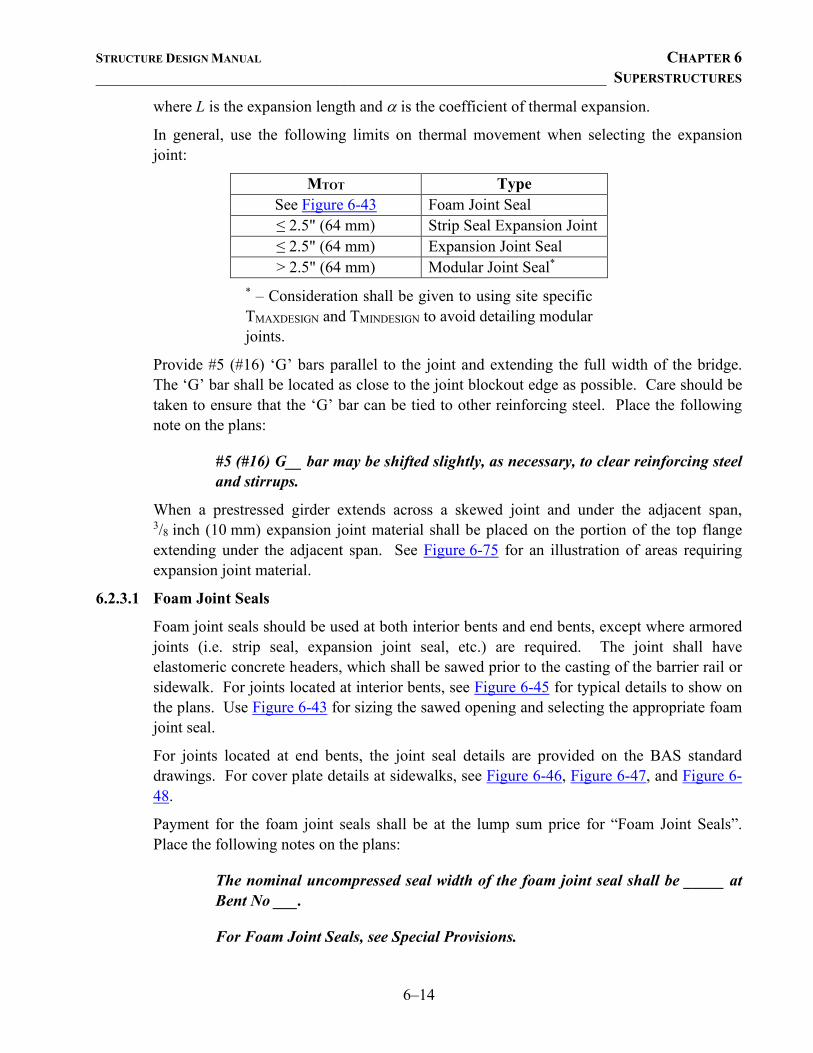
STRUCTURE DESIGN MANUAL CHAPTER 6 ________________________________________________________________ SUPERSTRUCTURES
6–14
where L is the expansion length and α is the coefficient of thermal expansion.
In general, use the following limits on thermal movement when selecting the expansion joint:
MTOT Type See Figure 6-43 Foam Joint Seal ≤ 2.5" (64 mm) Strip Seal Expansion Joint ≤ 2.5" (64 mm) Expansion Joint Seal > 2.5" (64 mm) Modular Joint Seal*
* – Consideration shall be given to using site specific TMAXDESIGN and TMINDESIGN to avoid detailing modular joints.
Provide #5 (#16) ‘G’ bars parallel to the joint and extending the full width of the bridge. The ‘G’ bar shall be located as close to the joint blockout edge as possible. Care should be taken to ensure that the ‘G’ bar can be tied to other reinforcing steel. Place the following note on the plans:
#5 (#16) G__ bar may be shifted slightly, as necessary, to clear reinforcing steel and stirrups.
When a prestressed girder extends across a skewed joint and under the adjacent span, 3/8 inch (10 mm) expansion joint material shall be placed on the portion of the top flange extending under the adjacent span. See Figure 6-75 for an illustration of areas requiring expansion joint material.
6.2.3.1 Foam Joint Seals
Foam joint seals should be used at both interior bents and end bents, except where armored joints (i.e. strip seal, expansion joint seal, etc.) are required. The joint shall have elastomeric concrete headers, which shall be sawed prior to the casting of the barrier rail or sidewalk. For joints located at interior bents, see Figure 6-45 for typical details to show on the plans. Use Figure 6-43 for sizing the sawed opening and selecting the appropriate foam joint seal.
For joints located at end bents, the joint seal details are provided on the BAS standard drawings. For cover plate details at sidewalks, see Figure 6-46, Figure 6-47, and Figure 6-48.
Payment for the foam joint seals shall be at the lump sum price for “Foam Joint Seals”. Place the following notes on the plans:
The nominal uncompressed seal width of the foam joint seal shall be _____ at Bent No ___.
For Foam Joint Seals, see Special Provisions.
STRUCTURE DESIGN MANUAL CHAPTER 6 ________________________________________________________________ SUPERSTRUCTURES
6–15
6.2.3.2 Strip Seal Expansion Joints
Detail a standard strip seal expansion joint for bridges with a calculated total thermal movement, MTOT ≤ 2.5 inches (64 mm) and located on any of the following:
• US Routes with a design year ADTT ≤ 2,500;
• NC Routes with a design year ADT ≥ 10,000;
• NC Routes with a design year ADTT ≥ 300. Strip seal expansion joints consist of a neoprene gland installed into steel “P” shaped retainer rails. To ensure the neoprene gland can be installed, maintain a 2 inch (50 mm) minimum roadway surface joint opening, normal to the centerline of joint at the 60°F (16°C) setting temperature. In addition, ensure there is a 1 inch (25 mm) minimum formed opening, normal to the centerline of joint when the superstructure is fully expanded.
Standard drawings, SSEJ1 through SSEJ4, are available and should be used for plan development. Delete any details that do not apply. SSEJ1 should be used in conjunction with SSEJ2 for barrier rails, or with SSEJ3 and SSEJ4 for sidewalks. Figure 6-136, Figure 6-137, and Figure 6-138 show standard drawings for a structure with a sidewalk.
Compute the total movement at the joint and show it on the “Movement and Setting at Joint” table on Standard SSEJ1. See Figure 6-139 for example computations for the “Movement and Setting at Joint” table. Also show the anticipated opening at the top and bottom of the joint at 45oF (7°C), 60oF (16°C), and 90oF (32°C).
For a strip seal expansion joint located at an interior bent, detail a permitted construction joint in the bridge deck in each adjacent span. For a strip seal expansion joint located at an end bent, detail a permitted construction joint in the bridge deck and the approach slab. The permitted construction joint shall be located a minimum distance of 2'-6" (760 mm), normal to the centerline of strip seal expansion joint as shown on Standard SSEJ1. For heavy skews, increase the distance to the location of the permitted construction joint in the bridge deck to prevent interference with the bent or end bent diaphragm. Do not show a separate quantity for the closure pours adjacent to the joints on the plans.
Standard SSEJ2 illustrates joint details adjacent to the barrier rail. For bridges on a skew, use Figure 6-53 to correctly show the “Plan of Strip Seal Expansion Joint” details on the left and right sides on the standard drawing. Note that strip seal expansion joints shall be turned up into a recessed area of the barrier rail along the skew. This requires extending the barrier rail on the approach slab, when strip seal expansion joints are used at end bents. Standards SSEJ3 and SSEJ4 illustrate joint details adjacent to a sidewalk. Use Figure 6-54 to correctly show the “Plan of Strip Seal Expansion Joint” details on the left and right sides of a sidewalk.
To facilitate properly locating permitted joints in the “P” shaped expansion joint rails, show the pavement marking alignment sketch on the plans. This information can be obtained from the Traffic Control Engineer. See Figure 6-56 for an example of the pavement
STRUCTURE DESIGN MANUAL CHAPTER 6 ________________________________________________________________ SUPERSTRUCTURES
6–16
marking alignment sketch. When sidewalks are detailed on the bridge, place the pavement marking alignment sketch and the plan view of the sidewalk cover plate on Standard SSEJ4. See Figure 6-55 for details of the sidewalk cover plate.
Cover plates in the recessed areas of the barrier rail or sidewalk are required over strip seal expansion joints. Cover plates shall be oriented with the bolts on the side of approaching traffic. The Type I cover plate has bolts on the left end of the plate when looking at the top of the plate, and the Type II cover plate has the bolts on the right end. In general, Type II will be used for two-way traffic, and Types I and II will be used for structures with one-way traffic. Calculate the length of the cover plate and show this dimension on standard drawing SSEJ4. See Figures 6-53 through 6-55 and Figures 6-27 through 6-30 for details on calculating the cover plate length for barrier rails and median barrier rails respectively.
For staged construction, temporary gland(s) should be installed in the first stage(s). Coordinate with the Traffic Control Engineer for the removal of the temporary gland(s) and installation of the final continuous gland. Place the following note on Standard SSEJ1:
A temporary gland is required for stage(s) ___. No separate payment will be made for the temporary gland(s).
Payment for the strip seal expansion joints shall be at the lump sum price for “Strip Seal Expansion Joints”. Place the following note on the plans:
For Strip Seal Expansion Joints, see Special Provisions.
6.2.3.3 Expansion Joint Seals
Detail a standard expansion joint seal with hold-down plates for bridges with a calculated total thermal movement, MTOT ≤ 2.5 inches (64 mm) and located on any of the following:
• Interstates; • US Routes with a design year ADTT > 2500.
Ensure a 1 inch (25 mm) minimum formed opening normal to the centerline of joint when the superstructure is fully expanded.
Standard drawings, EJS1 through EJS4, are available and should be used for plan development. EJS1 should be used in conjunction with EJS2 for barrier rails, or with EJS3 and EJS4 for sidewalks. Figures 6-49 through 6-51 show standard drawings for a structure with a sidewalk.
On Standard EJS1, delete any details that do not apply. The ‘J1’ bar in the “Expansion Joint Details” should be detailed and included in the Superstructure Bill of Material. See Figure 6-52 for a detail of the ‘J1’ bar. The ‘J1’ bar shall be epoxy coated. Compute the total movement and show it on the “Movement and Setting at Joint” table on Standard EJS1. See Figure 6-52 for example computations for the “Movement and Setting at Joint” table. For an expansion joint seal at an interior bent, detail a permitted construction joint in the bridge deck in each adjacent span. For an expansion joint seal located at an end bent,
STRUCTURE DESIGN MANUAL CHAPTER 6 ________________________________________________________________ SUPERSTRUCTURES
6–17
detail a permitted construction joint in the bridge deck and approach slab. The permitted construction joint shall be located a minimum distance of 2'-6" (760 mm), normal to the centerline of expansion joint as shown on Standard EJS1. For heavy skews, increase the distance to the permitted construction joint in the bridge deck to prevent interference with the bent or end bent diaphragm. Do not show a separate quantity for the closure pours adjacent to the joints on the plans.
Standard EJS2 illustrates general details. The “Plan of Expansion Joint Seal”, left and right sides shall be detailed on the standard drawing. See Figure 6-53 for details. Note that expansion joint seals are turned up into a recessed area of the barrier rail along the skew. This requires extending the barrier rail on the approach slab, when expansion joints seals are used at end bents.
Show the pavement marking alignment sketch on the plans. This information can be obtained from the Traffic Control Engineer. See Figure 6-56 for an example of the pavement marking alignment sketch. When sidewalks are detailed on the bridge, place the pavement marking alignment sketch and the plan view of the sidewalk cover plate on Standard EJS4. See Figure 6-55 for details of the sidewalk cover plate.
Cover plates are required over expansion joint seals. Cover plates shall be oriented with the bolts on the side of approaching traffic. The Type I cover plate has bolts on the left end of the plate when looking at the top of the plate, and the Type II cover plate has the bolts on the right end. In general, Type II will be used for two-way traffic, and Types I and II will be used for structures with one-way traffic. Calculate the length of the cover plate and show this dimension on the standard drawings. See Figures 6-53 through 6-55 and Figures 6-27 through 6-30 for details on calculating the cover plate length for barrier rails and median barrier rails respectively.
The “Plan of Expansion Joint Seal”, left and right sides, should be drawn on Standard EJS3. See Figure 6-54 for the detail showing the “Plan of Expansion Joint Seal” for sidewalks.
For staged construction, temporary gland(s) should be installed in the first stage(s). Coordinate with the Traffic Control Engineer for the removal of the temporary gland(s) and installation of the final continuous gland. Place the following note on Standard EJS1:
A temporary gland is required for stage(s) ___. No separate payment will be made for the temporary gland(s).
Payment for the expansion joint seals shall be at the lump sum price for “Expansion Joint Seals”. Place the following note on the plans:
For Expansion Joint Seals, see Special Provisions.
6.2.3.4 Modular Expansion Joint Seals
Use Structure Standards MEJS1 or MEJS2 should be used for plan development, but do not detail the joint. The contractor will submit detailed drawings and specifications for the proposed modular expansion joint seal. Compute the total movement as described above
STRUCTURE DESIGN MANUAL CHAPTER 6 ________________________________________________________________ SUPERSTRUCTURES
6–18
and show on the standard drawing. Also show cover plate details, the pavement marking alignment sketch and the “Plan of Modular Expansion Joint Seal”, left and right sides. See Figures 6-57 through 6-60 for these and other details to be included in the plans.
For modular expansion joints, no separate quantity is to be shown on the plans for the closure pours adjacent to the joint.
For modular expansion joints located at end bents, the backwall and the approach slab details shall be modified as shown in Figure 6-57.
Special snowplow protection of modular expansion joint seals will be necessary on bridges located in Divisions 7, 9, 11, 12, 13 or 14, Wake County, Durham County, Cabarrus County, or Mecklenburg County.
When snowplow protection is required, place the following note on plans:
Special snowplow protection is required. See Special Provision for Modular Expansion Joint Seals.
Otherwise, use the following plan note:
For Modular Expansion Joint Seals, see Special Provisions.
Payment for the modular expansion joint seals shall be at the lump sum price for “Modular Expansion Joint Seals”.
6.2.4 Bridge Rails
Railing, sidewalks and guardrail anchorage shall conform to the current AASHTO LRFD Bridge Design Specifications. All bridge railing systems not included in the Structure Standard Drawings shall satisfy the criteria in the AASHTO Manual for Assessing Safety Hardware (MASH), Second Edition. TL-2 rails, such as One Bar Metal Rails, may be used under the following conditions:
• Non-NHS routes, • Limited expected volume of truck traffic, • Design speeds less than or equal to 45 mph, or • In conjunction with a sidewalk.
6.2.4.1 Concrete Barrier Rails
Statewide and Regional tier bridges with reinforced concrete decks, and no sidewalks shall typically have an F-Shape Concrete Barrier Rail. See Figures 6-22, 6-23 and 6-24 for details. Sub-Regional tier bridges shall typically have a Vertical Concrete Barrier Rail (VCBR).
The New Jersey shaped Concrete Barrier Rail, which is detailed in Figures 6-20, 6-21 and 6-24, may be used on high speed highways where a 42" tall concrete barrier rail is not
STRUCTURE DESIGN MANUAL CHAPTER 6 ________________________________________________________________ SUPERSTRUCTURES
6–19
required. Typical applications for the New Jersey shape concrete barrier rail include protection of bents and sound barrier walls.
Standards CBR1 – “Concrete Barrier Rail” and CBR2 – “Vertical Concrete Barrier Rail” should be used in the plan development of cast-in-place reinforced concrete decks. Standards CBR1 and CBR2 are drawn to show general details. Modification may be needed to match a particular structure and rail. The plan view of the end of rail detail and the plan of spans showing reinforcing steel in barrier rail shall be shown on the Standard CBR1 or CBR2. For an example of the use of Standard CBR1, see Figure 6-26.
When foam joints with elastomeric concrete are used on a bridge with concrete barrier rail, #5 (#16) ‘S’ bars shall be installed using an adhesive bonding system near the joint as shown in Figure 6-25.
Provide an expansion joint in the rail, parapet or curb over all continuous bents. Also, use ½ inch (13 mm) expansion joint material at 30 foot (9 m) maximum centers when detailing any concrete barrier rail, metal rail with a concrete parapet or curb, or concrete median barrier rail. In addition, require grooved contraction joints to be tooled in the face of the rail, parapet or curb at each third point between expansion joints. Require one contraction joint at mid-point for rail, parapet or curb segments less than 20 feet. No contraction joints are required for rail, parapet or curb segments less than 10 feet. All reinforcing steel in concrete barrier rails, concrete parapets, curbs and median barrier rails shall be epoxy coated. For median barrier rail details, see Figures 6-27 through 6-31.
For permanent concrete median barrier rails, the width and height will be as required by the roadway typical section at the bridge. Coordinate with the Roadway Design Project Engineer to maintain the height of the median barrier on the bridge to that detailed on the approach roadway. When using New Jersey type median barrier, extend the barrier a minimum of 3 inches (75 mm) beyond the approach slab and square off the end.
Barrier rail details for cored slab structures are shown on the Standard PCS3 “Prestressed Cored Slab Unit”. The plan view showing the reinforcing steel in the end of the barrier rail should be shown on the Standard PCS3. Barrier rail details for box beam structures are shown on the Standard PCBB8 – “Prestressed Concrete Box Beam Unit.” For both superstructure types, the reinforcing steel and stirrups for the barrier rail shall be shown on the Plan of Spans.
6.2.4.2 Metal Rails
Eleven Structure Standard Metal Rail drawings, BMR1 through BMR11, are available for use in plan development.
Detail metal rails as shown on the Standards. The post spacing shall be a maximum of 6'-6" (1980 mm) on center for One Bar, Two Bar, and Three Bar Metal Rails. The post spacing shall be a maximum of 10'-0" on center for the 32" Alaska Rail and 42" Oregon Rail.
For Standard Metal Rails, provide the same movement capability in the rail’s expansion joint as that in the deck opening. Show the rail opening on the appropriate Metal Rail
STRUCTURE DESIGN MANUAL CHAPTER 6 ________________________________________________________________ SUPERSTRUCTURES
6–20
Standard. See Section 6.2.4.1 – Concrete Barrier Rails for details on expansion joints and grooved contraction joints in the concrete parapet or curb sections of metal rails.
One Bar Metal Rail is limited to routes that are not on the National Highway System (NHS), have a design speed of 45 MPH or below, and a limited volume of truck traffic is expected. When detailing One Bar Metal Rails, use Standards BMR1, BMR2 and GRA3. Place the post closest to the end post as shown on Standard BMR1. Place the next two posts spaced at a distance of one-half the normal post spacing, not to exceed 3'-3" (990 mm). Detail the post spacings and the expansion joint and grooved contraction joint locations in the parapet on Standard BMR2 in the designated area for “Plan of Rail Post Spacings”. Rail post bases shall not be located on expansion joints or grooved contraction joints in the parapet. Guardrail attachments should be shown on Standard GRA3. Also include the end post and parapet details shown in Figures 6-34 and 6-35 on an additional plan sheet.
Except as allowed in the Sub-Regional Tier Guidelines, Two Bar Metal Rails are used on structures carrying bicycle routes. When the rail is used on a bicycle route, requirements of the North Carolina Bicycle Facilities Planning and Design Guidelines shall be satisfied. When a future sidewalk is anticipated, the height of the concrete parapet should be increased so the total height above the future sidewalk meets the AASHTO criteria for pedestrian rails. When detailing Two Bar Metal Rails, use Standards BMR2, BMR3, BMR4 and GRA3. Place the post closest to the end post as shown on Standard BMR3. Place the next two posts spaced at a distance of one-half the normal post spacing, not to exceed 3'-3" (990 mm). Detail the post spacings and the expansion joint and grooved contraction joint locations in the parapet on Standard BMR2 in the designated area for “Plan of Rail Post Spacings”. Rail post bases shall not be located on expansion joints or grooved contraction joints in the parapet. Guardrail attachments should be shown on Standard GRA3. Also include the end post and parapet details shown in Figures 6-33 and 6-35 on an additional plan sheet. Figure 6-36 details parapet reinforcement for One and Two Bar Metal Rails on cored slabs. Figure 6-37 details parapet reinforcement for One and Two Bar Metal Rails on box beams.
The pay item for parapets for One and Two Bar Metal Rails shall be “1'-___ x ___" Concrete Parapet” (“___ x ___ mm Concrete Parapet”) and paid for per linear foot (meter).
Three Bar Metal Rails are used for structures with sidewalks. Use Standards BMR5, BMR6, BMR7, and GRA3. Place the post closest to the end post as shown on Standard BMR5. Place the next two posts spaced at a distance of one-half the normal post spacing, not to exceed 3'-3" (990 mm). Provide a “Plan of Rail Post Spacings” detail showing the post spacings and the expansion joint and grooved contraction joint locations in the sidewalk on an additional plan sheet. Rail post bases shall not be located on expansion joints or grooved contraction joints in the sidewalk. Also include the end post details on this additional sheet. See Figure 6-32 for end post details. Guardrail attachments should be shown on Standard GRA3.
STRUCTURE DESIGN MANUAL CHAPTER 6 ________________________________________________________________ SUPERSTRUCTURES
6–21
The 32" Alaska Rail and 42" Oregon Rail (a.k.a. open rails) have been recognized by the Federal Highway Administration as Test Level Four (TL-4) bridge rails in accordance with the AASHTO LRFD Bridge Design Specifications. The 32" Alaska Rail consists of two horizontal metal tubes attached to vertical metal posts with a height 32" above the riding surface of the bridge deck. The 42" Oregon Rail consists of three horizontal metal tubes attached to vertical metal posts with a height 42" above the riding surface of the bridge deck. Use of the 32" Alaska Rail and 42" Oregon Rail shall be limited to the following types of projects:
• bridge replacements in which the Project Commitments Sheet in the Environmental Document note the 32" Alaska Rail or the 42" Oregon Rail are required.
• bridge replacements where the conveyance of storm water requires the use of an open rail.
Use Standards BMR8 and BMR9 for the 32" Alaska Rail and BMR10 and BMR11 for the 42" Oregon Rail.
Place the post closest to the end post as shown on Standard BMR8 for the 32" Alaska Rail and Standard BMR10 for the 42" Oregon Rail. Place the next two posts spaced at a distance of one-half the normal post spacing, not to exceed 5'-0". Detail the post spacings and the expansion joint and grooved contraction joint locations in the curb on Standard BMR9 for the 32" Alaska Rail and Standard BMR11 for the 42" Oregon Rail in the designated area for “Plan of Rail Post Spacings”. Rail post bases shall not be located on expansion joints or grooved contraction joints in the curb. Guardrail attachments should be shown on Standard GRA3.
Include the end post and curb details shown in Figure 6-35c for the 32" Alaska Rail and Figure 6-35d for the 42" Oregon Rail on an additional plan sheet. Use Figure 6-35a for the 32" Alaska Rail and Figure 6-35b for the 42" Oregon Rail for curb reinforcement required in deck slabs. Use Figure 6-37a for the 32" Alaska Rail and Figure 6-37b for the 42" Oregon Rail for curb reinforcement required on cored slabs and box beams.
Detail additional reinforcement in deck slabs as shown in Figure 6-35a for the 32" Alaska Rail and Figure 6-35b for the 42" Oregon Rail. This reinforcing steel shall be included in addition to the typical ‘A’ bars.
Follow Standard PCS3 and Standard PCBB8 when detailing the reinforcement (S2 bars) in the top of cored slabs and box beams near each rail post on the Plan of Span sheet(s). This reinforcing steel should not be considered part of the shear resistance.
The metal rail pay item for the 32" Alaska Rail and 42" Oregon Rail shall be “32" Alaska Rail” and “42" Oregon Rail”, respectively, and paid for per linear foot. The concrete curb and end post pay item for the 32" Alaska Rail and 42" Oregon Rail shall be “1'-___ x ___" Concrete Curb” and paid for per linear foot.
STRUCTURE DESIGN MANUAL CHAPTER 6 ________________________________________________________________ SUPERSTRUCTURES
6–22
6.2.4.3 Aesthetic Rails
Other types of rail may be used in special cases only. The Texas Classic, TL-2, rail may be used where required, and shall be restricted to:
• Only when used with a sidewalk, • Non-NHS routes, and • Design speed ≤ 45 mph.
6.2.4.4 Guardrail Anchorage
Guardrail transition and attachment details shall satisfy the requirements of NCHRP Report 350. Roadway Design will recommend the location of guardrail attachments to the bridge on the Structure Recommendations or the Roadway plans.
Bolts used to attach the guardrail anchor unit to the bridge rail shall conform to requirements of ASTM A307.
Concrete Barrier Rails
For Concrete Barrier Rail (F-shape or New Jersey shape), the guardrail will attach directly to the barrier rail on the bridge using through-bolts and a B-77 GRAU. Standard GRA2 should be used for plan development. For Vertical Concrete Barrier Rail the guardrail will attach directly to the barrier rail on the bridge using through-bolts and a Type III GRAU. Standard GRA3 should be used for plan development. A sketch showing points of guardrail anchor assembly attachments should be drawn on the Standard GRA2 or GRA3.
Metal Rails
The end posts for metal rails are located on the bridge and have a vertical face to which the guardrail is attached with a Type III GRAU. Standard GRA3 should be used for plan development. A sketch showing points of guardrail anchor assembly attachments should be drawn on the Standard GRA3. See Figures 6-32, 6-33, and 6-34 for location of the guardrail anchor assembly.
6.2.4.5 Temporary Barrier Rail
For staged construction, the Work Zone Traffic Control Section of the Traffic Management Unit (Traffic Control) may require a temporary bridge rail. The pay item for temporary bridge rail will be a Traffic Control item and a Roadway detail or standard. Coordinate with Roadway Design and Traffic Control.
The Project Engineer shall contact the Roadway Project Engineer and the Traffic Control Section Head to determine the width of the bridge deck needed to maintain traffic during construction. This will determine the location of the temporary barrier and the offset distance from the back of the barrier to the edge of the slab.
If the offset distance is 6'-0" (1830 mm) or greater, the portable concrete barrier [Roadway Standard 1170.01] shall be used, but attachment to the bridge deck is not required.
STRUCTURE DESIGN MANUAL CHAPTER 6 ________________________________________________________________ SUPERSTRUCTURES
6–23
If the offset distance is less than 6'-0" (1830 mm), the portable concrete barrier [Roadway Standard 1170.01] shall be anchored to the slab. The same anchorage is required when a temporary barrier divides opposing traffic and is 2'-0" (600 mm) or less from the edge of any traffic lane. For anchored temporary barrier rail on a cored slab, detail alternating 5'-0" and 5'-1" spacings for the ferrule inserts. Anchored temporary barrier rail is not permitted on box beams. Traffic Control will be responsible for determining pay limits and estimating pay item quantities. The Project Engineer should include a sketch of the barrier including the offset distance and the following note should be added to the plans:
See Traffic Control Plans for location and pay limits of the anchored portable concrete barrier.
The Project Engineer shall submit the Preliminary General Drawing showing the beginning and ending approach slab stations to the Traffic Control Section Head and the Roadway Design Engineer as soon as practical.
6.2.4.6 Bridge Rails on Temporary Structure
Bridge rails on temporary structures shall be designed for either the Test Level 2 (TL-2) or the TL-3 crash test criteria defined in the AASHTO LRFD Bridge Design Specifications. A TL-2 rated barrier rail is the standard barrier rail on temporary structures, but if conditions warrant, a TL-3 bridge rail should be specified.
The Project Engineer shall evaluate the site conditions to determine if a TL-3 rail is required. Engineering judgment will be required to determine the appropriate rail type. During the Preliminary Field Inspection, visually evaluate and discuss the site conditions with the Area Bridge Construction Engineer or other personnel familiar with the location and the traffic conditions, to determine if a TL-3 bridge rail is warranted.
Conditions that warrant a TL-3 bridge rail include, but are not limited to:
• Structures on an NHS route. • Posted speed greater than or equal to 45mph. • High volume of heavy vehicles. • Unfavorable geometric site conditions. • High frequency of accidents based on historical data.
When a TL-3 barrier rail is required, place the following note on the plans:
The bridge rails on the temporary structure shall be designed for the AASHTO LRFD Test Level 3 (TL-3) crash test criteria. For Construction, Maintenance and Removal of Temporary Structure see Special Provisions.
STRUCTURE DESIGN MANUAL CHAPTER 6 ________________________________________________________________ SUPERSTRUCTURES
6–24
6.2.5 Sidewalks and Median Strips
When a sidewalk is required by the Structure Recommendations, it shall be 5'-0" (1500 mm) or 5'-6" (1650 mm) wide and minimum 6 inches (150 mm) high. See Figures 6-16 through 6-18 sidewalk details.
Cover for the reinforcing steel shall be 2 ½ inches (65 mm) minimum clear to the top bar and 1¼ inches (32 mm) clear to the bottom ‘B’ bar. The transverse reinforcing steel shall be #4 bars at 1'-0" (#13 bars at 300 mm) centers in the top of the sidewalk. Also, detail 2 - #4 (#13) 'U' bars in the transverse direction, at 7'-0" (2.1 m) centers in the longitudinal direction. The longitudinal reinforcing steel and 'U' bars shall be as detailed in Figures 6-16 through 6-18.
Where a permanent median strip is required on the bridge, the reinforcing steel shall be epoxy coated and detailed as shown in Figure 6-19.
Provide the same opening for the expansion joint in the median strip as that in the deck opening. See Figure 6-19 for details.
When a sidewalk or a median strip is shown, place the following note on the plans:
Grooved contraction joints, ½″ (12mm) in depth, shall be tooled in all exposed faces of the sidewalk [median strip] in accordance with Article 825-10(B) of the Standard Specifications. The contraction joints shall be located at a spacing of 8ft. to 10ft. (2.4m to 3.05m) between expansion joints. No contraction joints will be required for segments less than 10 feet (3.05m) in length.
6.2.6 Deck Drains
Coordinate with the Hydraulics Unit to ensure spread of water across the bridge deck on wide and/or long bridges is addressed. Deck drain requirements are shown on the Bridge Survey Report. Drains shall not be located over unprotected fill slopes, traffic lanes, shoulders, or in the vicinity of the end bent cap and berm.
Detail PVC pipes, 6 inch (152 mm) nominal diameter, as shown on the Bridge Survey Report. However, deck drains shall not be located within 5 feet (1.52 m) of the end bent berm.
In some circumstances, the Hydraulics Unit may require scuppers to be placed on the bridge. Use Standards BS1 and BS2 “Bridge Scupper Details”. When a collection system will not be attached to the structure, see Figures 6-14 and 6-15 for additional details. Detail the location of the inlet on the Typical Section and Plan of Span sheets.
Also, in some instances bridges identified by the Bridge Survey Report may require a closed drainage system to be detailed. Coordinate with the Hydraulics Unit to determine if a nominal increase in bridge deck width will allow elimination or shortening of the drainage system. Figures 12-33 and 12-34 show details for structure drainage systems.
STRUCTURE DESIGN MANUAL CHAPTER 6 ________________________________________________________________ SUPERSTRUCTURES
6–25
6.2.6.1 Stream Crossings
For drains to be used with prestressed concrete girder bridges, see Figure 6-12.
Cored slab and box beam bridges with an asphalt wearing surface shall be detailed with a flat faced rail to facilitate a 4" tall (above the wearing surface) drainage opening in the rail. The openings should be as wide as is practical, while maintaining the required concrete cover for the reinforcing bars in the rail. Note that the reinforcement in the Vertical Concrete Barrier Rail does not permit drainage openings located within 4 feet from the end of the span. When Concrete Barrier Rails (F-shape or New Jersey shape) have to be detailed, use 4" (102 mm) φ PVC drains. These drains shall be placed on top of the cored slab or box beam units and extended horizontally through the rail with a 4 inch (100 mm) minimum overhang. Detail an epoxy protective coating on the exterior face of cored slab or box beam units with drainage openings in the rail. See Figures 6-10 and 6-11 for details.
For drains to be used with rolled beam or plate girder bridges, see Figure 6-13. If the grade is greater than 2% on a normal crown deck 40 feet (12.2 m) or less in clear width, work with the Hydraulics Unit to see if the drain spacing can be increased from the initial recommendations.
Where deck drains have a significant impact on bridge aesthetics, the deck drains shall be painted. Place the same note on the plans that is used when deck drains are required on weathering steel grade separations. See Section 6.2.6.2 – Grade Separations.
6.2.6.2 Grade Separations
For drains to be used with prestressed concrete girder bridges, see Figure 6-12.
For drains to be used with rolled beam or plate girder bridges, see Figure 6-13. When deck drains are required on weathering steel grade separations, place the following note on the plans:
PVC deck drains shall be painted with two coats of brown primer meeting the requirements of Article 1080-11 of the Standard Specifications. Each coat shall be 2 dry mils (0.050 mm) thick. Deck drains shall be roughened prior to painting. No separate payment shall be made for painting PVC deck drains as this is considered incidental to the pay item for Reinforced Concrete Deck Slab [Sand Lightweight Concrete].
The above note shall be modified and placed on the plans when deck drains are required for painted structural steel superstructures.
6.2.6.3 Railroad Overheads
Drains that discharge on the railroad right-of-way are typically not allowed except in very unusual circumstances. In these instances, approval must be obtained from the Railroad for all drainage systems. Coordinate with the Hydraulics Unit to direct drainage away from railroad ditches.
STRUCTURE DESIGN MANUAL CHAPTER 6 ________________________________________________________________ SUPERSTRUCTURES
6–26
6.2.7 Supports for Attachments to Bridges
6.2.7.1 Utilities
All details and notes concerning utilities that are to be placed on the plans will be furnished by the Utilities Unit.
6.2.7.2 Traffic Signals, Cameras and Solar Array Platforms
Traffic control and traffic monitoring devices will typically be installed on the substructure bent cap. Provisions for support on the superstructure are addressed on a case-by-case basis. The Project Engineer shall coordinate with the Utilities Unit for the traffic signals and camera support locations and the Bridge Management Unit for solar array platform locations and light configuration.
6.3 PRESTRESSED CONCRETE GIRDERS
6.3.1 Design
Prestressed concrete girders shall be AASHTO Type II, Type III, Type IV, 63" (1600 mm) Modified Bulb Tee or 72" (1829 mm) Modified Bulb Tee, as shown in Figures 6-66 and 6-67. Design for the pretensioning method of prestressing with strands as described below. In general, the buildup shall be neglected in the section properties for composite design. For approximate span length limits, see Figure 11-3.
For continuous for live load deck slabs, use the same depth girders at continuous bent diaphragms.
Frequently, girders of the same size and similar length in the same bridge or within bridges of the same project require only slightly different number of strands. In this situation, consideration should be given to using the same number of strands for these girders.
For the use of prestressed concrete girders at Corrosive Sites, see Section 12-12.
6.3.1.1 Concrete
In general, conventional normal weight concrete materials should be specified. Concrete strengths up to 10,000 psi (68.9 MPa) may be used in prestressed members. Specify high strength concrete (> 6000 psi (41.4 MPa)) only in those spans where required by design. The final 28-day and release strengths of the concrete shall be no higher than required by design, rounded to the nearest 500 psi and 100 psi, respectively. For use of concrete strengths greater than 10,000 psi (68.9 MPa), consult with the Engineering Development Squad for approval. To prevent a sag in high strength concrete girders and girders with concrete strengths greater than 10,000 psi (68.9 MPa), ensure the deflection due to dead loads does not exceed the camber of the girder alone in place.
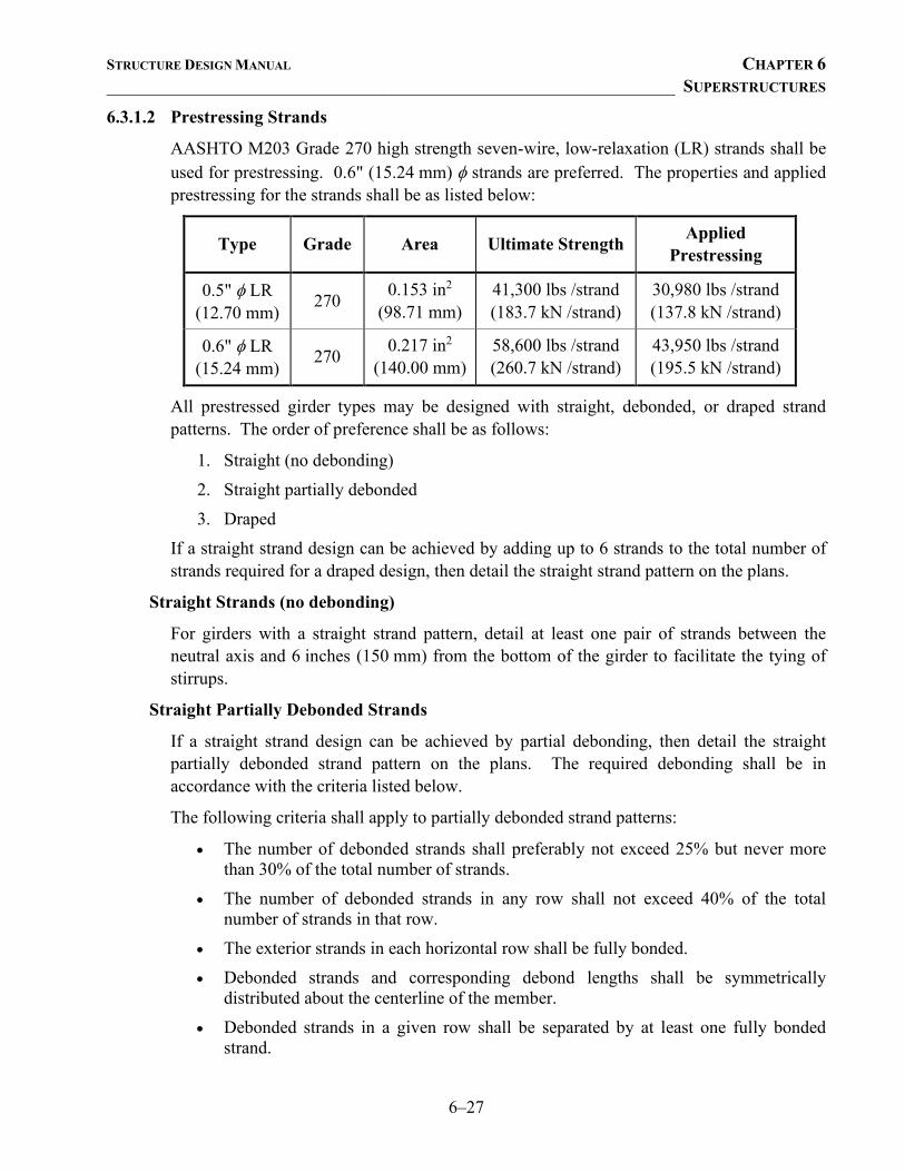
STRUCTURE DESIGN MANUAL CHAPTER 6 ________________________________________________________________ SUPERSTRUCTURES
6–27
6.3.1.2 Prestressing Strands
AASHTO M203 Grade 270 high strength seven-wire, low-relaxation (LR) strands shall be used for prestressing. 0.6" (15.24 mm) φ strands are preferred. The properties and applied prestressing for the strands shall be as listed below:
Type Grade Area Ultimate Strength Applied Prestressing
0.5" φ LR (12.70 mm)
270 0.153 in2
(98.71 mm) 41,300 lbs /strand (183.7 kN /strand)
30,980 lbs /strand (137.8 kN /strand)
0.6" φ LR (15.24 mm)
270 0.217 in2
(140.00 mm) 58,600 lbs /strand (260.7 kN /strand)
43,950 lbs /strand (195.5 kN /strand)
All prestressed girder types may be designed with straight, debonded, or draped strand patterns. The order of preference shall be as follows:
1. Straight (no debonding) 2. Straight partially debonded 3. Draped
If a straight strand design can be achieved by adding up to 6 strands to the total number of strands required for a draped design, then detail the straight strand pattern on the plans.
Straight Strands (no debonding)
For girders with a straight strand pattern, detail at least one pair of strands between the neutral axis and 6 inches (150 mm) from the bottom of the girder to facilitate the tying of stirrups.
Straight Partially Debonded Strands
If a straight strand design can be achieved by partial debonding, then detail the straight partially debonded strand pattern on the plans. The required debonding shall be in accordance with the criteria listed below.
The following criteria shall apply to partially debonded strand patterns:
• The number of debonded strands shall preferably not exceed 25% but never more than 30% of the total number of strands.
• The number of debonded strands in any row shall not exceed 40% of the total number of strands in that row.
• The exterior strands in each horizontal row shall be fully bonded. • Debonded strands and corresponding debond lengths shall be symmetrically
distributed about the centerline of the member. • Debonded strands in a given row shall be separated by at least one fully bonded
strand.
STRUCTURE DESIGN MANUAL CHAPTER 6 ________________________________________________________________ SUPERSTRUCTURES
6–28
• The number of debonded strands terminated at a given section shall not exceed four. • The minimum debond length shall be four feet and subsequent lengths shall vary in
two feet increments. Draped Strands
When straight or straight partially debonded strand patterns cannot meet design capacity requirements, design for a draped strand pattern.
Draped strand hold down points shall be located 5'-0" (1.500 m) on each side of the centerline of the prestressed girder. However, since steeply draped strands exert a considerable load on hold-down bolts in the bottom of the girder form, the slope on draped strands shall not exceed 12.5%. When the initial uplift force due to draped strands exceeds 20 kips (89 kN), place the following note on the plans:
The uplift force due to draped strands is ______ kips (kN).
The pattern for the release of the prestressing strands shall not be shown on the plans.
To facilitate the tying of shear reinforcing steel in girders with draped strand patterns, ensure the draped strands at the end of the prestressed members are not detailed in the top 8" of the girder, and place the following note on all girder plans:
The Contractor has the option to provide, at no additional cost to the department, 2 additional strands at the top of the girder to facilitate tying of the reinforcing steel. These strands shall be pulled to a load of 4500 lbs. (20 kN).
6.3.1.3 Girder Details
Ensure a minimum of 3 inch (75mm) clearance between the end of the girder and the end bent backwall. Verify the clearance check is satisfied after accounting for thermal expansion.
Include a girder layout sheet in the plans. See Figure 6-70 for an example.
Bevel the ends of the girders only when the grade, skew, or horizontal curve of the structure creates interference at end bents and joint locations. The ends of girders should not be beveled at the bents in continuous for live load spans. The tolerance on girder lengths should be considered when determining the necessity for bevel. Girder length tolerances are provided in Section 1078 of the Standard Specifications. Use the sloped bearing-to-bearing length of girders when the sloped distance exceeds the horizontal distance by more than 3/4 inch (19 mm).
Bridges with an expansion joint at a skewed interior bent require a notch in the top flange of the Type II, III or IV girder to prevent the deck concrete from bonding to the girder of the adjacent span. See Figure 6-75 for an illustration of the areas requiring a notch. Notches in the top flange at the end of the Type II and Type III girders are detailed in Standards PCG1 and PCG2. These notches will accommodate most skew conditions. For a 90° skew, eliminate the notch. Modify the ‘S3’ and ‘S4’ bars on the Type II girder standard
STRUCTURE DESIGN MANUAL CHAPTER 6 ________________________________________________________________ SUPERSTRUCTURES
6–29
drawing and the ‘S3’ and ‘S6’ bars on the Type III girder standard drawing to ‘S2’ bars. Add two horizontal ‘U’ shaped ‘S3’ stirrups in the top flange. For details of these modifications, see Figures 6-68 and 6-69.
Notches in the top flange at the end of the Type IV girder should be detailed on each structure as dictated by skew conditions. Modify the ‘S2’ bars to straight bars in pairs in the region of the notch. Move the ‘S3’ bars to clear the notch.
For Modified Bulb-Tee girders, prevent the deck concrete from bonding to the girder of the adjacent span by clipping the corner of the top flange as dictated by skew conditions. See Figure 6-75a for an illustration of the clipped flange areas. Modify the 'S6' bars to straight bars in pairs in the region of the clip. When necessary, move the 'S2' bars to clear the clipped area.
6.3.1.4 Composite Design
Extend the stirrups 6 inches (150 mm) above the top of the girder for a 2 ½ inch buildup. Adjust this extension when an increased buildup is required. Stirrup requirements (size and spacing) shall be as prescribed in the AASHTO LRFD Bridge Design Specifications.
6.3.2 Camber and Dead Load Deflection
Compute camber and dead load deflections for all interior and exterior girders at the following intervals based on span lengths:
• ≤ 100 feet (30.5 m) – 20th points.
• > 100 feet (30.5 m) and ≤ 200 feet (61 m) – 40th points.
• > 200 feet (61 m) – 60th points.
Show the camber and dead load deflections for all prestressed concrete girders in the following manner:
Camber (girder alone in place) =__________________↑ Deflection due to Superimposed D.L.* =__________________↓ Final camber (or deflection) =__________________↑ * Includes future wearing surface in superimposed dead load.
See Section 6.1.3 – Deflection and Camber Sign Convention.
Deflections and cambers shall be shown in feet (meters) to three decimal places, except the final camber which shall be shown to the nearest sixteenth of an inch (millimeter). Ensure the deflection due to dead loads does not exceed the camber of the girder alone in place.
6.3.2.1 Calculating Camber (Girder Alone In Place)
The 28-day camber for girders alone in place shall be based upon the research report titled Predicting Camber, Deflection, and Prestress Losses in Prestressed Concrete Members. Compute the camber for girders alone in place in accordance with the procedure outlined in Section 2.4.2 of this manual.
STRUCTURE DESIGN MANUAL CHAPTER 6 ________________________________________________________________ SUPERSTRUCTURES
6–30
6.3.3 Diaphragms
Diaphragms shall be provided at abutments and piers to resist lateral and torsional forces and transmit loads to points of support. Integral end bent bridges do not require an end bent diaphragm. See Section 7.3 – Integral End Bents for the criteria for detailing bridges with integral abutments.
6.3.3.1 Bent and End Bent Diaphragms
Bent diaphragms for simple span girders shall be cast-in-place concrete with a uniform depth of 1'-6" (460 mm) or 2'-0" (610 mm) below the bottom of the slab as shown in Figure 6-74. See Figures 6-74 and 6-75 for typical details of diaphragms at the interior bents. Show the #8 (#25) ‘K’ bars going over the girder. For skewed bridges, ensure the 'K' bars do not conflict with the 'S' bars projecting from the top of girder. For a 90º skew, the 10 inch (260 mm) diaphragms shall be located at the end of the girder.
When the face of the bent diaphragm is offset from the end of the girder, as shown on Figure 6-74, provide additional reinforcement in the concrete between the diaphragm and the centerline of the joint as follows:
• For an offset distance of 5 inches (130 mm) to less than 7 inches (180 mm), use one ‘K’ bar and #4 (#13) ‘S’ bars spaced at 1'-0" (300 mm).
• For an offset distance of 7 inches (180 mm) to less than 11 inches (280 mm), use two ‘K’ bars and #4 (#13) ‘S’ bars spaced at 1'-0" (300 mm).
• For an offset distance greater than 11 inches (280 mm), use three ‘K’ bars equally spaced and #4 (#13) ‘S’ bars spaced at 1'-0" (300 mm).
Bent diaphragms for simple span girders with a continuous for live load deck slab shall be detailed as shown in Figures 6-76 and 6-77. The #4 (#13) ‘U’ and ‘S’ bars shall be spaced at 1'-0" (300 mm) centers along the diaphragm.
6.3.3.2 Intermediate Diaphragms
The number of diaphragms required per span shall be as follows:
• None for spans less than 40 feet, • One at mid-span for spans between 40 and 100 feet, inclusive, • Two at third points for spans over 100 feet.
For skews between 70° and 110°, the diaphragm(s) shall be placed along the skew with bent connector plates, as shown on the standard drawings. For all other skew angles, detail the diaphragms normal to the girder web and stagger the connector plates.
For prestressed concrete girder superstructures with a closure pour, do not detail intermediate diaphragms in the staging bay.
STRUCTURE DESIGN MANUAL CHAPTER 6 ________________________________________________________________ SUPERSTRUCTURES
6–31
AASHTO Shapes
Detail intermediate steel diaphragms on all prestressed girder bridges using AASHTO Shapes II, III or IV.
A standard drawing, PCG10, is available for use. PCG10 should be used in conjunction with Standard Drawings PCG1 – 6 and may be used for all skew angles.
For corrosive sites, the steel diaphragms and assembly hardware shall be metallized, with no option to galvanize. Modify the standard notes to require metallization only.
Modified Bulb Tees
Detail intermediate steel diaphragms on all prestressed girder bridges using modified bulb-tee shapes. Standard Drawing PCG11 is available, and should be used in conjunction with the standard drawings for modified bulb-tee girders. Ensure the web through-bolts do not conflict with strands. The bent plate shall be centered on the web and shall be 4" shorter than the vertical face of the web.
In corrosive or highly corrosive environments, detail an optional cast-in-place concrete intermediate diaphragm with 1¼" (31.75 mm) φ tie rods, which shall be tightened before casting the concrete. See Figures 6-78 and 6-79 for details. The length of the tie rods shall not exceed 40 feet (12 m). Diaphragms may be staggered in order to keep the length of the tie rod below 40 feet (12 m). Diaphragms shall be placed at right angles to the centerline of the roadway.
When optional concrete diaphragms are detailed, place the following notes on the plans:
Temporary struts shall be placed between prestressed girders adjacent to the diaphragms and the nuts on the 1 ¼" (31.75 mm) φ tie rods shall be fully tightened before diaphragms are cast. Struts shall remain in place 3 days after concrete is placed. The tie rods shall be re-tightened after the struts have been removed.
Concrete in bent and intermediate diaphragms may be Class A in lieu of Class AA. Payment shall be made under the unit contract price for Reinforced Concrete Deck Slab. (Simple spans)
Concrete in intermediate diaphragms may be Class A in lieu of Class AA. Payment shall be made under the unit contract price for Reinforced Concrete Deck Slab. (Continuous for live load spans)
Also, use a grouted recess for the tie rod ends on the exterior girder. See Figure 6-80 for details.
STRUCTURE DESIGN MANUAL CHAPTER 6 ________________________________________________________________ SUPERSTRUCTURES
6–32
6.4 PRESTRESSED CONCRETE CORED SLABS
6.4.1 Design
Cored slabs are to be of the AASHTO standard shape Type SIII-36 (18" cored slab), Type SIV-36 (21" cored slab), or 24" tall Type SIV-36 (24" cored slab) as shown in Figure 6-81, and are to be designed for prestressing with straight strands. For approximate span length limits, see Figure 11-3.
The concrete and prestressing strands shall be as described in Section 6.3.1. 0.6" (15.24 mm) φ low-relaxation strands are preferred. Specify high strength concrete only in spans where required by design.
Where debonded strands are required, indicate the strands to be debonded on the standard drawing, as illustrated in Figure 6-82. Place the following note on the plans:
Bond shall be broken on these strands for a distance of ______ feet (meters) from end of cored slab unit. See Standard Specifications Article 1078-7.
Cored slabs shall be limited to skews between 60° and 120° and vertical grades of 4% or less. Cored slabs are permitted on vertical curves as long as the minimum dimension from the top of the barrier rail to the top of the wearing surface is maintained.
Transversely, cored slabs may be used on superelevations of 4% or less. When the travel way is superelevated or crowned, consider reducing the thickness of the wearing surface by supporting the cored slab units on a sloped cap. Similarly, limit the bent cap cross-slope to a maximum of 4%. If a crowned bent cap is necessary, limit the cap roll-over (algebraic difference in rates of cross slope) to 2%. To satisfy cap roll-over limit, detail at least 2 or 3 level units at the crown point.
Certain combinations of skew, vertical curve, and superelevation or normal crown can result in theoretical cap slopes that would require twisting of cored slab units to seat. Therefore, ensure longitudinal and transverse cap slopes are set to permit proper seating.
In most cases, cored slabs should be limited to tangent horizontal alignments. However, on slight curves, it may be economical to design a cored slab structure detailed with curved pavement markings. If this option is used, the Project Engineer shall coordinate with the Roadway Design Unit as described below.
When the Structure Recommendations do not show the overall width to an even 3 foot increment, but it is determined that cored slabs are the preferred structure type, the Structure Project Engineer shall increase the recommended out-to-out width to the next even 3'-0" (914 mm) increment and inform the Roadway Project Engineer of the necessary adjustment in the clear roadway width. See the available form letters via the Structures Management web page.
Refer to the Bridge Survey Report (BSR) when determining the bridge layout for stream crossings. In general, the span lengths shown in the BSR represent the cored slab unit
STRUCTURE DESIGN MANUAL CHAPTER 6 ________________________________________________________________ SUPERSTRUCTURES
6–33
length for each span. Increase the total bridge length to accommodate the end bent and bent joint openings and the cap width necessary to support the approach slab.
The barrier rail shall be placed such that there is a 1" (25 mm) offset from the edge of the exterior unit to the exterior face of the barrier rail. The barrier rail shall be attached to the exterior units by casting reinforcing steel into the exterior units and pouring the barrier rail after the units are post-tensioned. Use the Vertical Concrete Barrier Rail whenever possible. For use of a One or Two Bar Metal Rail, see Figure 6-36. For use of the 32" Alaska Rail, see Figure 6-37a. For use of the 42" Oregon Rail, see Figure 6-37b. The 32" Alaska Rail and 42" Oregon Rail shall be placed such that there is no offset from the edge of the exterior unit to the exterior face of the curb.
When required, a minimum sidewalk width of 5'-0" (1500 mm) or 5'-6" (1650 mm) shall be used unless otherwise recommended. Place the sidewalk and parapet so the offset from the edge of the exterior unit to the exterior face of the parapet is 1" (25 mm). See Figure 6-17 for details.
If the overall width is not in an even 3'-0" increment, increase the sidewalk width as necessary and inform the Roadway Project Engineer of any adjustment so the guardrail location, where necessary, can be adjusted accordingly.
When a future sidewalk is anticipated, the embedded "S" bars in the cored slab units are not required.
Use Standard Drawings PCS1 – 4 for plan development. Standard Drawing PCS1, PCS2, or PCS4 shall be used in combination with Standard PCS3.
The standard drawings provide general details. Some modification or adjustment will be required to suit a particular structure. The barrier rail details are drawn for a 2 inch (50 mm) asphalt wearing surface measured at the gutterline. To accommodate large cambers, this wearing surface thickness may exceed 2 inches (50 mm) at the centerline of the bearing. See Section 6.4.3 – Overlays for wearing surface types and minimum thickness. When the thickness of the wearing surface is adjusted, the reinforcing details for the barrier rail should be modified accordingly. See Figures 6-82 through 6-84 for an example use of the standard drawings.
Use the cored slab standard design plans whenever possible. When site conditions preclude use of standard design plans, make every attempt to match the standard design plan prestressing strand pattern. Utilizing the strand pattern detailed in standard design plans provides potential savings in production costs and minimizes the possibility for fabrication errors.
The offset dimension for the ‘S3’ bar is based on 1 inch (25 mm) minimum clear distance to the voids. For constructability of exterior cored slab units, detail the spacing for the ‘S’ embedded barrier rail reinforcing bars and the ‘U’ shaped ‘S2’ stirrups to coincide. For cored slab structures with skews less than 75° or greater than 105°, provide additional
STRUCTURE DESIGN MANUAL CHAPTER 6 ________________________________________________________________ SUPERSTRUCTURES
6–34
skewed stirrups between the ‘S1’ and the first ‘S2’ stirrup such that the spacing between stirrups does not exceed 1'-0" (300 mm). See Figure 6-85 for details.
For the use of cored slabs at a Corrosive Site, see Section 12-12.
6.4.2 Top-Down Construction
21" or 24" cored slab units may be used when top-down construction is anticipated or required. For bearing-to-bearing span lengths up to 50 feet (16.76 m), top-down construction loads are accommodated by the HL93 live load. However, for spans greater than 50 feet (16.76 m), the designer should consider force effects of anticipated construction loads such as operating and travelling crane loads.
The following top-down construction bearing-to-bearing span length limits shall apply:
• 21" Cored Slab – 50 feet (15.24 m). • 24" Cored Slab – 60 feet (18.29 m).
However, the attainable span length may be reduced by the size of the crane required to construct the foundation. Factors that influence the size of the crane include pile type (e.g. prestressed concrete piles), design pile tonnages in excess of 130 tons, and pile driving equipment with energy ranges greater than 40 foot-kips. Refer to the Foundation Recommendations for factors that may influence the crane size and coordinate with the Geotechnical Engineering Unit and the Working Drawings Approval Group to assess whether the proposed span lengths are attainable.
When top-down construction is anticipated or required, place a note on the Preliminary General Drawing to notify and facilitate coordination with the Construction and Geotechnical Engineering Units. For notes to be placed on the Preliminary General or General Drawing, see Chapters 4 and 5.
6.4.3 Overlays
Cored slab bridges shall have a concrete or asphalt overlay. The type of overlay shall be based on the bridge location and traffic conditions. Use Figure 6-61 for selecting the overlay type.
A concrete overlay shall be detailed on bridges that satisfy at least one of the following criteria:
• Bridges on NHS routes • Bridges with design year TTST greater than 100 • Low water bridges located in Divisions 11-14
For each span, detail the minimum and maximum overlay thickness at the gutterline. If the bridge has a normal crown cross-section, also include the minimum and maximum overlay thickness at the crest of the crown section. In addition, detail the embedded barrier rail ‘S’
STRUCTURE DESIGN MANUAL CHAPTER 6 ________________________________________________________________ SUPERSTRUCTURES
6–35
bar for the minimum overlay thickness, show the minimum height of the rail, and place the following note on the plans:
The minimum height of the rail is shown. The height of the rail varies while the top of the rail follows the profile of the gutterline.
When through-the-rail drainage is required, use a flat-faced rail with drainage slots through the rail parapet whenever possible. When selecting a flat-faced rail, ensure that the rail Test Level (TL) rating is appropriate for the route and design speed. See Section 6.2.4 – Bridge Rails.
Detail the fewest number of joints in overlays.
6.4.3.1 Concrete
The top of the cored slab units shall receive a raked finish in accordance with the Section 1078-15 of the Standard Specifications.
Detail a minimum concrete overlay thickness of 3½ inches. The overlay shall be reinforced with #3 (#10) bars spaced at 6" (150mm) centers in both the longitudinal and transverse directions. This reinforcing steel mat shall be placed such that the 2" (50mm) clear cover is maintained throughout the overlay surface. Reinforcement in the transverse direction may be placed along the skew. Include full plan details to show the overlay reinforcing steel with a complete bill of material, and the required beam bolsters at mid-span and centerline bearing. If different height beam bolsters are required to maintain the clear cover, then show the required beam bolster heights at or near the gutter line and at the location that requires the tallest beam bolster. The maximum beam bolster spacing shall be 2'-0" (600mm).
Show the dimensions for the minimum overlay thickness at mid-span and the overlay thickness at centerline bearing on the Typical Section. Indicate that the overlay thickness at centerline bearing is based on the predicted deflection due to concrete overlay.
The overlay shall be placed after the barrier rails have been constructed and have cured. Longitudinal joints in the overlay shall not be permitted, except where required for staged construction. Place the following note on the plans:
Placement of the concrete wearing surface shall occur after casting the concrete rail. The cost of the #3 (#10) bars cast with the concrete wearing surface shall be included in the unit price bid for concrete wearing surface. For Concrete Wearing Surface, see special provisions.
Since the concrete overlay is only lightly reinforced, avoid detailing relatively deep sections of the concrete overlay. If the roadway plans show a normal crown on a bridge that will have a concrete overlay, then request the Roadway Unit revise that section of roadway to a constant superelevation to minimize the overlay thickness or detail the bent caps with a slope top of cap where practical.
STRUCTURE DESIGN MANUAL CHAPTER 6 ________________________________________________________________ SUPERSTRUCTURES
6–36
For bridges up to 150 feet in length, detail a fixed condition on both ends of all spans. Then, detail a backer rod near the bottom of the joint filled with grout. The grout should be the same as that used to fill the anchor bolt-holes. For bridges over 150 ft. detail the minimum number of expansion joints in the overlay.
For a fixed-fixed condition, the concrete overlay shall be continuous over the joint. In addition detail additional 20'-0" long #4 (#13) longitudinal reinforcing steel bars spaced at 6" (150mm), centered over the joint, and placed between the longitudinal bars in the overlay. Standard Drawings PCS1 and PCS2 show details for the fixed-fixed and fixed-expansion conditions, except the overlay shall be concrete.
For an expansion-expansion condition, detail an expansion joint in the concrete overlay. Minimize the number of joints in the overlay by detailing the minimum number of expansion-expansion conditions in the bridge. Expansion joints in the concrete overlay shall be detailed with foam joints that incorporate the standard elastomeric concrete filled blockout. See standard drawing PCBB1 for the joint details.
6.4.3.2 Asphalt
The top of the cored slab units shall receive a broom finish in accordance with the Section 1078-15 of the Standard Specifications.
For asphalt overlays, use a flat-faced rail with drainage slots through the rail parapet whenever possible.
The minimum asphalt overlay thickness shall be 1½ inches.
Detail a fixed condition on both ends of all spans. Then, detail a backer rod near the bottom of the joint filled with grout. The grout should be the same as that used to fill the anchor bolt-holes. Standard Drawings PCS1 and PCS2 show details for the fixed-fixed and fixed-expansion conditions.
6.4.4 Camber and Dead Load Deflection
The camber and dead load deflection shall be shown for all cored slab spans in the following manner:
Camber (Girder alone in place) =__________________↑ Deflection due to Superimposed D.L.* =__________________↓ Final camber (or deflection) =__________________↑ * Includes future wearing surface, except when a concrete overlay is used.
See Section 6.1.3 – Deflection and Camber Sign Convention.
All deflections and cambers shall be shown to the nearest sixteenth of an inch (millimeter). Ensure the deflection due to dead loads does not exceed the camber of the girder alone in place.
STRUCTURE DESIGN MANUAL CHAPTER 6 ________________________________________________________________ SUPERSTRUCTURES
6–37
See Section 6.3.2 – Camber and Dead Load Deflection for the method used to compute camber and deflection.
When a concrete overlay is detailed, do not include deflections due to the rail or the future wearing surface in the deflection due to superimposed dead load.
6.4.4.1 Calculating Camber (Girder Alone In Place)
The 28-day camber for girders alone in place shall be based upon the research report titled Predicting Camber, Deflection, and Prestress Losses in Prestressed Concrete Members. Compute the camber for girders alone in place in accordance with the procedure outlined in Section 2.4.2 of this manual.
6.4.5 Diaphragms
Diaphragms shall be detailed along the skew and shall be located at:
• Mid-span for spans less than 40 feet (12 m). • Third points for spans 40 feet (12 m) or more.
A 2½" (64 mm) φ hole shall be formed through the center of the diaphragm for the post-tensioned strand. The strand shall be 0.6" (15.24 mm) φ seven-wire, high strength low-relaxation. 24" cored slab units shall have a pair of holes at each diaphragm location. The anchorage recess for the strand shall be grouted. See Figures 6-86, 6-86a, and 6-87 for details. Place the following note on the plans:
Post-tensioning shall be done in accordance with the Standard Specifications.
6.4.6 Permitted Threaded Inserts
Detail permitted threaded inserts on the exterior face of exterior cored slab units. Threaded inserts provide the option of installing falsework to:
• gain access for forming concrete bridge components such as curbs, barrier rails, parapets, and sidewalks,
• facilitate the application of form liners to barrier rail faces and/or • prevent falling debris during construction.
The size of the threaded inserts will be provided by the Contractor prior to casting the cored slab units. See Standard Drawings PCS1, PCS2, and PCS4 for a detail of the insert. The appropriate notes are included on Standard Drawing PCS3.
STRUCTURE DESIGN MANUAL CHAPTER 6 ________________________________________________________________ SUPERSTRUCTURES
6–38
6.5 PRESTRESSED CONCRETE BOX BEAMS
6.5.1 Design
Box beams shall be similar to AASHTO standard shapes Type BII-36 and BIII-36, which are detailed to the dimensions and section properties shown in Figure 6-88, and are to be designed for prestressing with straight strands. For approximate span length limits see Figure 11-3. Box beams shall be constructed in a side-by-side layout, similar to the practice for cored slab bridges and shall have a backwall at the end bents.
The concrete and prestressing strands shall be as described in Section 6.3.1 with 0.6" (15.24 mm) φ low-relaxation strands. Specify high strength concrete only in spans where required by design. Avoid designing spans with strands located near the neutral axis in the walls of the box beams, and ensure strands do not conflict with the diaphragms.
Where debonded strands are required, indicate the strands to be debonded on the standard drawing. Place the following note on the plans:
Bond shall be broken on strands as shown for the specified length from each end of the box beam. See Standard Specifications Article 1078-7.
Box beams shall be limited to skews between 60° and 120° and vertical grades of 4% or less. Box beams are permitted on vertical curves as long as the minimum dimension from the top of the barrier rail to the top of the wearing surface is maintained.
Transversely, box beams may be used on superelevations of 4% or less. When the travel way is superelevated or crowned, consider reducing the thickness of the wearing surface by supporting the box beam units on a sloped cap. Similarly, limit the bent cap cross-slope to a maximum of 4%. If a crowned bent cap is necessary, limit the cap roll-over (algebraic difference in rates of cross slope) to 2%. To satisfy cap roll-over limit, detail at least 2 or 3 level units at the crown point.
Certain combinations of skew, vertical curve, and superelevation or normal crown can result in theoretical cap slopes that would require twisting of box beam units to seat. Therefore, ensure longitudinal and transverse cap slopes are set to permit proper seating.
In most cases, box beams should be limited to tangent horizontal alignments. However, on slight curves, it may be economical to design a box beam structure detailed with curved pavement markings. If this option is used, the Project Engineer shall coordinate with the Roadway Design Unit as described below.
When the Structure Recommendations do not show the overall width to an even 3 foot increment but it is determined that box beams are the preferred structure type, the Structure Project Engineer shall increase the recommended out-to-out dimension to the next even 3'-0" (914mm) increment and inform the Roadway Project Engineer of the necessary adjustment to the clear roadway width. See the available form letters via the Structures Management web page.
STRUCTURE DESIGN MANUAL CHAPTER 6 ________________________________________________________________ SUPERSTRUCTURES
6–39
Refer to the Bridge Survey Report (BSR) when determining the bridge layout for stream crossings. In general, the span lengths shown in the BSR represent the box beam unit length for each span. Increase the total bridge length to accommodate the end bent and bent joint openings and the cap width necessary to support the approach slab.
The barrier rail shall be placed such that there is a 1" (25 mm) offset from the edge of the exterior unit to the exterior face of the barrier rail. The barrier rail shall be attached to the exterior units by casting reinforcing steel into the exterior units and pouring the barrier rail after the units are post-tensioned. Use the Vertical Concrete Barrier Rail whenever possible. For use of a One or Two Bar Metal Rail, see Figure 6-37. For use of the 32" Alaska Rail, see Figure 6-37a. For use of the 42" Oregon Rail, see Figure 6-37b. The 32" Alaska and 42" Oregon Rails shall be placed such that there is no offset from the edge of the exterior unit to the exterior face of the curb.
When required, a minimum sidewalk width of 5'-0" (1500mm) or 5'-6" (1650mm) shall be used unless otherwise recommended. Place the sidewalk and parapet so the offset from the edge of the exterior unit to the exterior face of the parapet is 1" (25mm). See Figure 6-18 for details.
If the overall width is not in an even 3'-0" increment, increase the sidewalk width as necessary and inform the Roadway Project Engineer of any adjustment so the guardrail location, where necessary, can be adjusted accordingly.
When a future sidewalk is anticipated, the embedded "S" bars in the box beam units are not required.
Six standard drawings, PCBB1 and PCBB4–8 are available and should be used in plan development. Standards PCBB1 and PCBB8 shall be used in combination with Standards PCBB4 through PCBB7.
The standard drawings provide general details. Some modifications or adjustments will be required to suit a particular structure. The barrier rails are detailed for a 3½" (90mm) concrete wearing surface measured at the gutterline. To accommodate large cambers, this wearing surface thickness may exceed 3½" (90mm) at the centerline of the bearing. See Section 6.5.3 - Overlays for wearing surface type and minimum thickness. When the thickness of the wearing surface is adjusted, the reinforcing details for the barrier rail should be modified accordingly.
Use the box beam standard design plans whenever possible. When site conditions preclude use of standard design plans, make every attempt to match the standard design plan prestressing strand pattern. Utilizing the strand pattern detailed in standard design plans provides potential savings in production costs and minimizes the possibility for fabrication errors.
For the use of box beams at a Corrosive Site, see Section 12-12.
STRUCTURE DESIGN MANUAL CHAPTER 6 ________________________________________________________________ SUPERSTRUCTURES
6–40
6.5.2 Top-Down Construction
Box beams may be used when top-down construction is anticipated or required. For bearing-to-bearing span lengths up to 50 feet (16.76 m), top-down construction loads may be approximated by the HL93 live load. However, for spans greater than 50 feet (16.76 m), the designer should consider force effects of anticipated construction loads, such as operating and travelling cranes.
The following top-down construction bearing-to-bearing span length limit shall apply:
• 33" and 39" Box Beam – 65 feet (19.81 m). However, the attainable span length may be reduced by the size of the crane size required to construct the foundation. Factors that influence the size of the crane include pile type (e.g. prestressed concrete piles), design pile tonnages in excess of 130 tons, and pile driving equipment with energy ranges greater than 40 foot-kips. Refer to the Foundation Recommendations for factors that may influence the crane size and coordinate with the Geotechnical Engineering Unit and the Working Drawings Approval Group to assess if proposed span lengths are attainable.
When top-down construction is anticipated or required, place a note on the Preliminary General Drawing to notify and facilitate coordination with the Construction and Geotechnical Engineering Units. For notes to be placed on the Preliminary General or General Drawing, see Chapters 4 and 5.
6.5.3 Overlays
Box beam bridges shall have a concrete or asphalt overlay. The type of overlay shall be based on the bridge location and traffic conditions. Use Figure 6-61 for selecting the overlay type.
A concrete overlay shall be detailed on bridges that satisfy at least one of the following criteria:
• Bridges on NHS routes • Bridges with design year TTST greater than 100 • Low water bridges located in Divisions 11–14
For each span, detail the minimum and maximum overlay thickness at the gutterline. If the bridge has a normal crown cross-section, also include the minimum and maximum overlay thickness at the crest of the crown section. In addition, detail the embedded barrier rail ‘S’ bar for the minimum overlay thickness, show the minimum height of the rail, and place the following note on the plans:
The minimum height of the rail is shown. The height of the rail varies while the top of the rail follows the profile of the gutterline.
STRUCTURE DESIGN MANUAL CHAPTER 6 ________________________________________________________________ SUPERSTRUCTURES
6–41
When through-the-rail drainage is required, use a flat-faced rail with drainage slots through the rail parapet whenever possible. When selecting a flat-faced rail, ensure that the rail Test Level (TL) rating is appropriate for the route and design speed. See Section 6.2.4 – Bridge Rails.
Eliminate joints in overlays whenever possible.
6.5.3.1 Concrete
The top of the box beam units shall receive a raked finish in accordance with the Section 1078-15 of the Standard Specifications.
Detail a minimum concrete overlay thickness of 3½ inches, which shall be reinforced with #3 (#10) bars spaced at 6" (150mm) centers in both the longitudinal and transverse directions. This reinforcing steel mat shall be placed such that the 2" (50mm) clear cover is maintained throughout the overlay surface. Reinforcement in the transverse direction may be placed along the skew. Include full plan details to show the overlay reinforcing steel with a complete bill of material, and the required beam bolsters at mid-span and centerline bearing. If different height beam bolsters are required to maintain the clear cover, then show the required beam bolsters heights at or near the gutter line and at the location that requires the tallest beam bolsters. The maximum beam bolster spacing shall be 2'-0" (600mm).
Show the dimensions for the minimum overlay thickness at mid-span and the overlay thickness at centerline bearing on the Typical Section. Indicate that the overlay thickness at centerline bearing is based on the predicted deflection due to concrete overlay.
The overlay shall be placed after the barrier rails have been constructed and have cured. Longitudinal joints in the overlay shall not be permitted. Place the following note on the plans:
Placement of the concrete wearing surface shall occur after casting the concrete rail. The cost of the #3 (#10) bars cast with the concrete wearing surface shall be included in the unit price bid for concrete wearing surface. For Concrete Wearing Surface, see special provisions.
Since the concrete overlay is only lightly reinforced, avoid detailing relatively deep sections of the concrete overlay. If the roadway plans show a normal crown on a bridge that will have a concrete overlay, then request the Roadway Unit revise that section of roadway to a constant superelevation to minimize the overlay thickness or detail the bent caps with a slope top of cap where practical.
Detailing fixed conditions on box beams with concrete overlays should be evaluated on a case-by-case basis. Details for the joints should mitigate the potential for cracking in the overlay as a result of beam deflection and/or thermal movement.
For a fixed-fixed condition, the concrete overlay shall be continuous over the joint. In addition detail additional 20'-0" long #4 (#13) longitudinal reinforcing steel bars spaced at
STRUCTURE DESIGN MANUAL CHAPTER 6 ________________________________________________________________ SUPERSTRUCTURES
6–42
6" (150mm), centered over the joint, and placed between longitudinal bars in the overlay. Also, detail a backer rod near the bottom of the joint filled with grout. The grout should be the same as that used to fill the anchor bolt-holes. Standard Drawing PCBB1 shows details for the fixed-fixed and fixed-expansion conditions.
Detail the minimum the number of expansion joints. Expansion joints on box beam bridges should be detailed with foam joints that incorporate the standard elastomeric concrete filled blockout. See standard drawing PCBB1.
6.5.3.2 Asphalt
The top of the box beam units shall receive a broom finish in accordance with the Section 1078-15 of the Standard Specifications.
The minimum asphalt overlay thickness shall be 1½ inches.
For bridges up to 150 feet in length, detail a fixed condition on both ends of all spans. Also, detail a backer rod near the bottom of the joint filled with grout. The grout should be the same as that used to fill the anchor bolt-holes. Standard Drawing PCBB1 shows details for the fixed-fixed and fixed-expansion conditions, except the overlay shall be asphalt.
6.5.4 Camber and Dead Load Deflection
The camber and dead load deflection shall be shown for all box beam spans in the following manner:
Camber (Girder alone in place) =__________________↑ Deflection due to Superimposed D.L.* =__________________↓ Final camber (or deflection) =__________________↑ * Includes future wearing surface, except when a concrete overlay is used.
See Section 6.1.3 – Deflection and Camber Sign Convention.
All deflections and cambers shall be shown to the nearest sixteenth of an inch (millimeter). Ensure the deflection due to dead loads does not exceed the camber of the girder alone in place.
See Section 6.3.2 – Camber and Dead Load Deflection for the method used to compute camber and deflection.
When a concrete overlay is detailed, do not include deflections due to the rail or the future wearing surface in the deflection due to superimposed dead load.
6.5.4.1 Calculating Camber (Girder Alone In Place)
The 28-day camber for girders alone in place shall be based upon the research report titled Predicting Camber, Deflection, and Prestress Losses in Prestressed Concrete Members. Compute the camber for girders alone in place in accordance with the procedure outlined in Section 2.4.2 of this manual.
STRUCTURE DESIGN MANUAL CHAPTER 6 ________________________________________________________________ SUPERSTRUCTURES
6–43
6.5.5 Diaphragms
Diaphragms shall be detailed along the skew and shall be located 8 feet from the ends in addition to the following locations:
• Mid-span for spans up to 60 feet (18.29 m), • Third points for spans between 60 feet (18.29 m) and 85 feet (25.91 m), and • Quarter points for spans over 85 feet (25.91 m).
Use Figure 6-89 to estimate diaphragm locations.
A pair of 2 ½" (64 mm) φ holes, for the post-tensioning strands, shall be formed through the diaphragm and shall be located symmetrically about the mid-height of the box beam section. The post-tensioning strand shall be seven wire, high strength Grade 270, 0.6" (15.24 mm) φ, low-relaxation strands. The anchorage recess for the post-tensioning assembly shall be grouted as shown on the Standard Drawings.
6.5.6 Permitted Threaded Inserts
Detail permitted threaded inserts on the exterior face of exterior box beam units. Threaded inserts provide the option of installing falsework to:
• gain access for forming concrete bridge components such as curbs, barrier rails, parapets, and sidewalks,
• facilitate the application of form liners to barrier rail faces and/or • prevent falling debris during construction.
The size of the threaded inserts will be provided by the Contractor prior to casting the box beam units. See Standard Drawings PCBB2, PCBB4, and PCBB6 for a detail of the insert. The appropriate notes are included on Standard Drawing PCBB1.
6.6 STEEL PLATE GIRDERS AND ROLLED BEAMS
6.6.1 Structural Steel
AASHTO M270 Grade 50W (345W) shall typically be used for in steel superstructures. 50W (345W) weathering steel is preferred to painted structural steel for routine use when atmospheric corrosion is not a problem. For structural steel material specifications, see Section 3-4. For restrictions on the use of weathering steel, see Section 12-12.
Hybrid girders may offer a cost effective alternative to non-hybrid 50W and should be considered in steel superstructures. Utilize the HPS 70W (485W) steel in the flanges of the higher moment regions and Grade 50W (345W) steel in the remaining flanges and in the web.
STRUCTURE DESIGN MANUAL CHAPTER 6 ________________________________________________________________ SUPERSTRUCTURES
6–44
6.6.2 Design
Use the fewest number of beams or girders consistent with a reasonable deck design. Use buildups over all beams and girders. When metal stay-in-place forms are used, the buildups shall be the same width as the beam or girder top flange. If metal stay-in-place forms are not used, the buildups shall be detailed approximately 6 inches (150 mm) wider than the beam flange. Indicate on the plans that a chamfer is not required on the corners of these buildups. Buildups should not be provided on the outside of exterior girders. Instead, detail the bottom of slab overhang to be approximately parallel to the deck slope. Show the depth of overhang at the outside edge of the slab to the nearest ¼" (6mm). See Figure 6-90 for details.
Design all beams and girders for composite action. The slab thickness for composite design shall be the slab thickness less ¼ inch (6 mm) monolithic wearing surface. In general, the buildup shall be neglected in the section properties for composite design.
For economical and fatigue reasons, do not design rolled beams with cover plates except to match existing beams for rehabilitation and widening projects.
The minimum W-section used as a primary member shall be a W 27x84 (W 690x125). The overhang widths for these rolled beams shall not exceed 27 in (690 mm). When a W27 (W690) steel section is required, place the following note on the plans:
Needle beam type supports are required for the overhang falsework in the spans with 27" (690 mm) beams.
Ensure a minimum of 3 inch (75 mm) clearance between the end of the girder and the end bent backwall. Verify the clearance check is satisfied after accounting for thermal expansion.
The end of beams and girders at expansion joints skewed at 90° should be 1½ inches (40 mm) from the formed opening of the joint. The end of beams and girders for skewed bridges should be located further from the edge of the expansion joints so that the top flange, which would otherwise project into the joint, can be clipped ½ inch (13 mm) from the formed opening of the joint. See Figure 6-91 for details.
When designing economical welded plate girders, observe the following rules:
• Maintain a constant web depth and vary the areas of the flange plates. Flange widths in field sections shall be kept uniform where practical. It is more economical to design a field section with a uniform flange width and a varying flange thickness than vice versa. When a constant flange width is used in a given field section, the fabricator can order wide plates of varying thickness and make transverse butt splices. The fabricator can then cut the pre-welded pieces longitudinally to the specified constant flange width.
• Limit the flange thickness change ratio to 2:1. For example, if using a 2 inch (50 mm) flange plate, do not transition to less than a 1 inch (25 mm) flange plate. For flange and web butt joint welding details, see Figure 6-92.
STRUCTURE DESIGN MANUAL CHAPTER 6 ________________________________________________________________ SUPERSTRUCTURES
6–45
• Utilize flange plate thicknesses between ¾ in (20 mm) and 3 inches (70 mm). • Limit the number of welded flange geometry transitions. Approximately 600 lbs
(270 kg) of flange material must be saved to justify the introduction of a welded flange transition. For spans less than 100 feet (30 m) in length, a savings of 500 lbs (230 kg) of flange material will generally offset the cost of a welded flange transition. Use a maximum of two flange transitions or three plate sizes in a particular field section. This case usually applies in the negative moment region. In positive moment areas, one flange size can often be carried through the field section. Bolted field splices in continuous girders are good locations for changing flange geometry as this eliminates a welded butt splice.
• Limit the number of different plate thickness used in a particular bridge or group of bridges within a project. The amount of a particular plate thickness that the fabricator can order is directly related to the unit cost of the material. The lightest steel bridge is not necessarily the most economical. Consideration must be given to the cost of fabrication processes in order to realize an economical design. For metric projects, refer to the Metric Structural Steel Special Provision for typical plate thicknesses.
• If the girder length exceeds 135 feet (41.1 m), detail the plans for a bolted field splice. When transitioning the web plate thickness at a field splice, increment the web thickness at least 1/8 inch (3 mm) so that 1/16 inch (1.5 mm) fill plates may be used.
• In negative moment regions of continuous girders, provide transverse stiffeners in lieu of detailing a web shop splice to transition to a thicker web.
6.6.2.1 Bearing Stiffeners & Bearing Stiffeners used as Connector Plates
Plate Girders
Bearing stiffeners shall be designed according to the AASHTO LRFD Bridge Design Specifications. Bearing stiffeners shall consist of plates welded to both sides of the girder web at all bearing locations. The connections to the web shall be designed to transmit the full bearing force due to factored loads. This requirement also applies to plate girders with integral end bents. For bearing stiffener details, see Figure 6-112.
Bearing stiffeners may be used as connector plates for end bent and bent diaphragms. For skews between 70° and 110°, the bearing stiffener may be placed along the skew and the diaphragms may be bolted to the bearing stiffener. For skews less than 70° or greater than 110°, a separate bent gusset plate should be used to connect the diaphragm to the bearing stiffener, which is placed perpendicular to the girder web.
When the bearing stiffener is used as a connector plate, detail the bearing stiffener mill to bear at the bottom flange and provide fillet welds at the top and bottom of the stiffener. See Section 6.6.2.3 – Connector Plates for details. If the girder design requires both bearing stiffeners that do not serve as connector plates and bearing stiffeners that are also used as connector plates, then provide separate details to avoid unnecessary welding to the bottom flange of the bearing stiffener only locations. Alternatively, clearly indicate, with a note,
STRUCTURE DESIGN MANUAL CHAPTER 6 ________________________________________________________________ SUPERSTRUCTURES
6–46
that welding to the bottom flange is only required where the bearing stiffener also serves as a connector plate.
When the bearing stiffener is used as a connector plate, provide a minimum width and thickness of the plate on the plans; the fabricator will determine the actual width based on connection clearances. Place the following note under the bearing stiffener detail on the plans:
Bearing stiffener may require coping if wider than bottom flange.
When bearing stiffeners cannot be used as connector plates, detail the diaphragms approximately 1'-0" (300 mm) from the center of the bearing to clear the bearing stiffener and provide separate connector plates. See Section 6.6.2.3 – Connector Plates for details.
At continuous bents, check the fatigue stress range for the bearing stiffener and/or connector plate for fatigue detail Category C', per the AASHTO LRFD Bridge Design Specifications.
Rolled Beams
Bearing stiffeners shall be provided on both sides of the web for interior beams and the inside of the web for exterior beams. Place the following note on the plans:
Stiffeners are not required on the outside of exterior beams.
These bearing stiffeners shall serve as connector plates for the diaphragms and shall be detailed parallel to the end of the beam. Therefore, when the ends of the beam are beveled for grade, the end stiffeners will be vertical. If the ends of the beam are not beveled, the end stiffeners shall be normal to the beam flange. Typically, these stiffeners shall have widths such that they provide approximately ½ inch (13 mm) distance to the edge of flange. The stiffener thickness shall not be less than 1/12 its width, nor less than 3/8 inch (9 mm).
6.6.2.2 Transverse Stiffeners
Transverse stiffeners for plate girders shall be designed according to the AASHTO LRFD Bridge Design Specifications. Transverse stiffeners shall consist of plates welded to either one or both sides of the web. Stiffeners in straight girders not used as connector plates shall be welded to the compression flange and shall have a tight fit on the tension flange. Stiffeners used as connector plates for diaphragms or cross-frames shall be welded to the top and bottom flanges.
It is recommended that designers select a web thickness such that a minimum number of transverse stiffeners are required. Partially stiffened webs (2-3 stiffeners near bearing) are more cost effective. The determination of length of the web to be stiffened must be made by considering the material and labor cost of the stiffener versus the cost of the web material saved. For relative cost analyses, assume that the cost of the stiffener steel is four times greater than that of the web.
STRUCTURE DESIGN MANUAL CHAPTER 6 ________________________________________________________________ SUPERSTRUCTURES
6–47
For interior girders, transverse stiffeners should be placed on alternating sides of the web. For exterior girders the transverse stiffeners shall be placed on the inside of the web only. For transverse stiffener details, see Figure 6-112. Stiffener plate details shall include the weld termination details of Figure 6-113. The welded connections for stiffeners to beam or girder webs shall be in accordance with Figure 6-114.
Longitudinal stiffeners shall be avoided.
6.6.2.3 Connector Plates
Connector plates shall be welded to the top and bottom flanges of the girder. See Figure 6-101. When detailing connector plates, do not provide a width dimension as the fabricator will determine the width. Connector plate details shall include the weld termination details of Figure 6-113. The welded connections for connector plates to beam or girder webs shall be in accordance with Figure 6-114.
When the skew is less than 70° or greater than 110°, a bent gusset plate shall be used to attach the diaphragm member to the connector plate. The gusset plate shall be the same thickness as the connector plate. The number of bolts used to connect the gusset plate to the connector plate shall be consistent with the connections of Figures 6-95 through 6-100 or as required by design. The height of the gusset plate and welds shall be detailed as shown in the example of Figure 6-115. Do not detail the gusset plate width or bend radius.
6.6.2.4 Shear Connectors
In general, concrete bridge decks shall be made composite with their supporting members. Shear connectors and other connections between decks and girders shall be designed for force effects calculated on the basis of full composite action.
For all steel beams and girders designed for composite action, use ¾" (19.05 mm) φ by 5 inch (127 mm) minimum length studs. For proper slab penetration and concrete cover, the shear connectors shall be detailed to satisfy the AASHTO LRFD Bridge Design Specifications. When an increased buildup is required, an increase in the length of the shear connectors may be required. Account for the thickness of bolted field splice plates at locations with a bolted field splice when computing lengths of shear studs.
In the negative moment region of continuous spans, use a consistent number of studs per row as that used in the positive moment region and space the studs at 2'-0" (600 mm). This spacing may be modified at locations of high stress in the tension flange as per the AASHTO LRFD Bridge Design Specifications.
For shear connectors attached to the channel bent diaphragms, use ¾" (19.05 mm) φ by 4 inch (102 mm) stud length.
See Figure 6-116 for shear connector details.
STRUCTURE DESIGN MANUAL CHAPTER 6 ________________________________________________________________ SUPERSTRUCTURES
6–48
6.6.3 Diaphragms and Cross Frames
Diaphragms shall be located at the end of the structure, across interior supports, and intermittently along the span in accordance with the AASHTO LRFD Bridge Design Specifications. Diaphragms or cross-frames for rolled beams and plate girders should be as deep as practicable.
For economical reasons, consider uniformity in the diaphragm member sizes and types used on a bridge or throughout a project.
6.6.3.1 Bent and End Bent Diaphragms
Diaphragms or cross-frames at supports shall be proportioned to transmit all lateral components of force from the superstructure to the bearings that provide lateral restraint.
At the end bents and interior bents of simple spans, use steel diaphragms with ¾" (19.05 mm) φ shear studs anchored into a concrete edge beam. See Figures 6-93 and 6-94. In the bent diaphragms show the ‘K’ bars going over the beams or girders. If the concrete diaphragm is wider than 2 feet (610 mm), use three #5 (#16) ‘K’ bars equally spaced at the bottom of the concrete diaphragm. For integral end bent bridges, do not detail a diaphragm at the abutment.
For rolled beams, use C 12x20.7 (C 310x31) channels for 27 inch (690 mm) beams, C 15x33.9 (C 380x50) channels for beams 30 inches (760 mm) through 33 inches (840 mm), and MC 18x42.7 (MC 460x64) channels for beams 36 inches (920 mm) deep. For details see Figures 6-95 through 6-97.
For plate girders less than 36 inches (920 mm) deep, Figure 6-97 may be used if the connector plate is detailed as in Figure 6-101, with the connector plate welded to the top and bottom flange. For plate girders 36 inches (920 mm) through 48 inches (1220 mm) deep, end bent and interior bent diaphragms shall be as shown in Figure 6-98. For plate girders greater than 48 inches (1220 mm) deep, diaphragms must be designed on an individual basis. These should be detailed similar to Figures 6-99 and 6-100. The dimension between the bottom flange and the diaphragm or bracing member must be determined by the detailer. Show the minimum length and the weld size required for gusset plate attachments.
Bent diaphragms for continuous spans shall be similar to the intermediate diaphragms. For spans that are continuous over the bent, place the interior bent diaphragms perpendicular to the girder and use one bearing stiffener as a connector plate. See Section 6.6.2.1 – Bearing Stiffeners & Bearing Stiffeners used as Connector Plates. For spans with a joint at the bent, place the bent diaphragms along the skew using details similar to end bent diaphragms.
6.6.3.2 Intermediate Diaphragms
Intermediate diaphragms or cross-frames should be provided at uniform or nearly uniform spacing. Place the intermediate diaphragms normal to the beams or girders for all skews. A maximum spacing of 25 feet (7.6 m) shall be used for all intermediate diaphragms. For
STRUCTURE DESIGN MANUAL CHAPTER 6 ________________________________________________________________ SUPERSTRUCTURES
6–49
integral abutments, detail an intermediate diaphragm approximately 1-2 feet from the face of the abutment.
For rolled beam simple spans, use C 12x20.7 (C 310x31) channels for 27 inch (690 mm) beams, C 15x33.9 (C 380x50) channels for beams 30 inches (760 mm) through 33 inches (840 mm), and MC 18x42.7 (MC 460x64) channels for beams 36 inches (920 mm) deep. For details see Figures 6-102 through 6-104.
For rolled beam continuous spans, use C 15x33.9 (C 380x50) channels for all beams less than 36 inches (920 mm) and MC 18x42.7 (MC 460x64) for beams 36 inches (920 mm) deep as shown in Figures 6-103 and 6-104.
For plate girders less than 36 inches (920 mm) deep, Figure 6-104 may be used if the connector plate is detailed as in Figure 6-101, with the connector plate welded to the top and bottom flange. For plate girders 36 inches (920 mm) through 48 inches (1220 mm) deep, diaphragms shall be detailed as shown in Figure 6-105. Intermediate diaphragms for girders 49 inches (1245 mm) through 60 inches (1525 mm) deep shall be as shown in Figure 6-106. Cross-frames for girders greater than 60 inches (1525 mm) deep must be designed on an individual basis. These should be detailed similar to Figures 6-107 through 6-109. The dimension between the bottom flange and the cross-frame bracing member must be determined by the detailer. Show the minimum length and the weld size required for the cross-frame, gusset plate or lateral bracing attachments.
When traffic must be maintained during construction beneath a bridge with plate girders greater than 60 inches (1525 mm) in depth, provide both cross-frames of Figures 6-107 and 6-108 in the plans. Label the cross-frame with the welded gusset plates, Figure 6-107, as an optional intermediate diaphragm. Place the following note on the plans:
At the Contractor's option, the diaphragm with the welded gusset plates may be used in lieu of the diaphragm with bolted angles at no additional cost to the Department.
Staged Construction
For staged construction in all steel superstructures detail intermediate diaphragms in the staging bay. The diaphragms in the closure bay shall be bolted to the connector plates. Provide vertical slots in one connector plate and horizontal slots in the opposing connector plate to allow for field adjustment. The slots shall be 1 inch (25 mm) by 1 ½ inch (40 mm) with structural plate washers. For long spans, consider longer slots to accommodate larger deflections. Place the following note on the plans:
Nuts on bolts for connecting diaphragm to connector plate shall be left loose for purpose of adjustment until both sides of slab have been poured.
For both normal crown and superelevated bridges, detail the diaphragm parallel to the bridge deck.
STRUCTURE DESIGN MANUAL CHAPTER 6 ________________________________________________________________ SUPERSTRUCTURES
6–50
6.6.4 Bolted Field Splices
In general, bolted field splices should only be detailed when required to limit the girder field section lengths to 135 feet (41.1 m) or when known shipping limitations exist. In continuous spans, necessary splices should be made at or near points of dead load contraflexure. Splices located in areas subject to stress reversals shall be investigated for both positive and negative flexure. Bolted field splices shall be designed as per the AASHTO LRFD Bridge Design Specifications. Flange and web splices shall be symmetrical about the centerline of the splice.
When the engineer anticipates a bolted field splice will be required for access to the bridge site, then detail an optional bolted field splice on the plans and include the appropriate plan quantities. Place the following note on the plans:
At the Contractor's option, the optional bolted field splice may be omitted, provided the Contractor obtains all permits required for transporting the longer piece lengths.
Detail girders without an optional bolted field splice when there is a perceived benefit.
6.6.5 Bolted Connections
High strength bolts shall be shown on the plans for all field bolted connections including diaphragms and beam or girder splices.
The contact surface of bolted parts to be used in the slip-critical connections shall be Class A for AASHTO M270 Grade 50 (345) steel or Class B for AASHTO M270 Grade 50W (345W) steel. Design these connections with a minimum of 1/8 inch (3 mm), preferably ¼ inch (6 mm), additional edge distance beyond the AASHTO LRFD Bridge Design Specification requirements to provide greater tolerance for punching, drilling and reaming. Use a 3 inch (75 mm) minimum distance from the centerline of the web splice to the first row of bolts. See Figure 6-117.
When AASHTO M270 Grade 50W (345W) steel is specified, the high strength bolts, nuts and washers shall conform to AASHTO M164 Type 3. When the finish paint is applied in the structural steel fabrication shop, use galvanized erection bolts that meet the requirements of AASHTO M164.
Place the following note on the plans:
Tension on the ASTM A325 bolts shall be calibrated using direct tension indicator washers in accordance with Article 440-8 of the Standard Specifications.
For bolts used to attach the guardrail anchor unit to the bridge rail, see Section 6.2.4.4 – Guardrail Anchorage.
STRUCTURE DESIGN MANUAL CHAPTER 6 ________________________________________________________________ SUPERSTRUCTURES
6–51
6.6.6 Fabrication and Construction Details
For steel beams on grade, the ends of the beams or girders should be beveled to maintain concrete cover. A correction should be made to the length between the bearings of beams and girders on a grade when the sloped distance exceeds the horizontal distance by more than ¼ inch (6 mm). Show the sloped length in parentheses on the bottom flange detail. Place the following notes on the plans:
End of beams and girders shall be plumb.
For steel beams or girders on a skew less than 60o or more than 120o detail a top flange clip (bevel) to avoid possible interference with the backwall.
When detailing welded steel girders, show the flange and web butt joint welding details in accordance with Figure 6-92. Shop web splices should not be located within 2'-0" (600 mm) of a shop flange splice. Indicate where the additional shop web and flange splices will be allowed by placing the following note on the plans:
Permitted flange and web shop splices shall not be located within 15 feet (4.5 m) of maximum dead load deflection (nor within 15 feet (4.5 m) of intermediate bearings of continuous units). Keep 2 feet (600 mm) minimum between web and flange shop splices. Keep 6" (150 mm) minimum between connector plate or transverse stiffener welds and web or flange shop splices.
For continuous spans and/or girders with integral end bents, include in the plans a designation of the regions where the top flange is in tension and include the following note:
No welding of forms or falsework to the top flange will be permitted in this region.
Girders on skewed supports typically undergo out of plane rotation, which displaces the top flange transversely from the bottom flange resulting in an out of plumb web. It is desirable for the girders to be plumb after placement of all dead load. Therefore, Fabricators will be required to detail erection plans for total dead load fit up. Place the following note on the plans:
Fabricators shall detail diaphragm members and connections for full dead load fit up. Girders shall be plumb after the full amount of dead load is applied.
6.6.7 Charpy V-Notch
All structural steel furnished for primary members subject to tensile stresses shall meet requirements of the longitudinal Charpy V-Notch Test.
For rolled beams, place the following note on the plans:
STRUCTURE DESIGN MANUAL CHAPTER 6 ________________________________________________________________ SUPERSTRUCTURES
6–52
A Charpy V-Notch Test is required on all beam sections, cover plates and splice plates as shown on the plans and in accordance with Article 1072-7 of the Standard Specifications.
For simple span plate girders, place the following note on the plans:
A Charpy V-Notch Test is required for web plates, bottom flange plates, bottom flange splice plates and web splice plates (if used) for all girders and in accordance with Article 1072-7 of the Standard Specifications.
For continuous plate girders, see Figure 6-118 for the Charpy V-Notch Test notes and the girder components that require testing.
For integral end bents, the length of the top flange in the vicinity of the integral end bent subject to tensile stresses may be estimated as twenty percent of the span length (0.2L), or may be determined by running the girder design with fixed ends for live loads. See Figure 6-118 for the Charpy V-Notch notes and the girder components that require testing.
For horizontally curved girders, place the following note on the plans:
For Charpy V-Notch Test, see Special Provisions.
6.6.8 Deflections and Cambers
Provide deflections and cambers for all interior and exterior beams/girders at the following intervals based on span lengths:
• ≤ 100 feet (30.5 m) – 20th points.
• > 100 feet (30.5 m) and ≤ 200 feet (61 m) – 40th points.
• > 200 feet (61 m) – 60th points.
Tabulate the deflections, vertical curve ordinates, and superelevation ordinate as follows:
Deflection due to weight of steel =__________________↓ Deflection due to weight of slab =__________________↓ Deflection due to weight of rail =__________________↓ Total Dead Load Deflection =__________________↓ Vertical Curve Ordinate =__________________↑ or ↓ Superelevation Ordinate =__________________↑ or ↓ Required Camber =__________________↑ or ↓
See Section 6.1.3 – Deflection and Camber Sign Convention.
Deflections, ordinates and cambers shall be shown in feet (meters) to three decimal places, except the Required Camber, which shall be shown to the nearest sixteenth of an inch (millimeter).
When a slab contains several pours, additional diagrams should provide the deflections at the appropriate points due to each individual pour. These diagrams are used by the
STRUCTURE DESIGN MANUAL CHAPTER 6 ________________________________________________________________ SUPERSTRUCTURES
6–53
Contractor to determine ordinates for grading with a longitudinal screed and are required for the interior beams or girders only. Since longitudinal screeds are disallowed for pours exceeding 85 feet (26 m) in length, it is not necessary to provide pour deflection diagrams for pours exceeding this limit.
The superelevation ordinate is required when a bridge is on a horizontal curve or spiral alignment. It is also required on the spans of tangent bridges that have a variable superelevation. The superelevation ordinate is generally deducted from the total dead load deflection but must, in special cases, be added to the total dead load deflection. The superelevation ordinate should not be combined with the vertical curve ordinate but shown separately in the table of dead load deflections.
6.6.8.1 Special Procedure for Non-Composite Dead Load Deflections
Non-composite dead load deflections for steel bridges shall be based on the North Carolina State University research report titled Development of a Simplified Procedure to Predict Dead Load Deflections of Skewed and Non-skewed Steel Plate Girders.
Compute the non-composite dead load deflections in accordance with the procedure outlined in Section 2-5 of this manual.
6.6.8.2 Camber for Continuous Spans
In addition to the deflection curves for continuous spans, camber curves should be shown and labeled “Schematic Camber Ordinates”. On vertically curved bridges place the following note on the plans:
Slope for the zero camber base line varies.
6.6.8.3 Camber for Rolled Beams
If the total dead load deflection plus vertical curve and superelevation ordinates is less than ¾ inch (19 mm), do not show a “Required Camber.”. Place the following note on the plans:
No shop camber required, turn natural mill camber up.
Otherwise, detail simple span beams to be cambered to the nearest 1/16 inch (1 mm). When one beam in a span requires camber, detail all of the beams in that span with camber.
Rolled Beams on a Sag Vertical curve
When preparing the table of dead load deflections and camber, careful consideration should be given to ensure that no thinning of the slab occurs in a sag vertical curve. When the net deflection (dead load deflection minus any superelevation ordinate) exceeds the sag vertical curve ordinate by more than ¼ inch (6 mm), the natural mill camber shall be turned up in the usual manner. However, if the net deflection equals or exceeds the sag vertical curve ordinate by less than ¼ inch (6 mm), call for the natural mill camber to be turned downward. If the sag vertical curve ordinate is greater than the net deflection, the bridge
STRUCTURE DESIGN MANUAL CHAPTER 6 ________________________________________________________________ SUPERSTRUCTURES
6–54
seats should be adjusted accordingly and the plans should call for the natural mill camber to be turned downward.
6.6.9 Construction Notes
Place the following applicable notes on the plans:
Structural steel erection in a continuous unit shall be complete before falsework or forms are placed on the unit.
Previously cast concrete in a continuous unit shall have attained a minimum compressive strength of 3000 psi (20.7 MPa) before additional concrete is cast in the unit. (This note should be reworded when simple spans have multiple pours.)
Barrier rail in a continuous unit shall not be cast until all slab concrete in the unit has been cast and has reached a minimum compressive strength of 3000 psi (20.7 MPa).
Barrier rail in each span shall not be cast until all slab concrete in that span has been cast and has reached a minimum compressive strength of 3000 psi (20.7 MPa). (This note should be used for all simple spans.)
Direction of casting deck concrete shall be from the fixed bearing end toward the expansion bearing end of the span. (For simple span steel girders with a total expansion length of 150 feet (46 m) or greater)
The Contractor may, when necessary, propose a scheme for avoiding interference between metal stay-in-place form supports or forms and beam/girder stiffeners or connector plates. The proposal shall be indicated, as appropriate, on either the steel working drawings or the metal stay-in-place form working drawings.
6.6.10 Constructibility Guidelines
During preliminary design, consult with the Area Bridge Construction Engineer to develop an anticipated girder erection sequence. When traffic conditions, environmental constraints, size, and/or geometric complexity of the bridge favor prescribing a constructability plan, then detail a proposed erection sequence in the plans. Describe the proposed erection sequence with plan notes and sketches of the various critical erection stages. Check for potential girder overstresses or uplift during erection under the various loading conditions of the proposed erection sequence.
Steel girders can exhibit unanticipated behavior, e.g. buckling, after erection, but prior to becoming composite with the concrete deck. If lateral bracing is not present, the weak-axis (transverse) bending stiffness can be significantly less than the strong-axis (vertical)
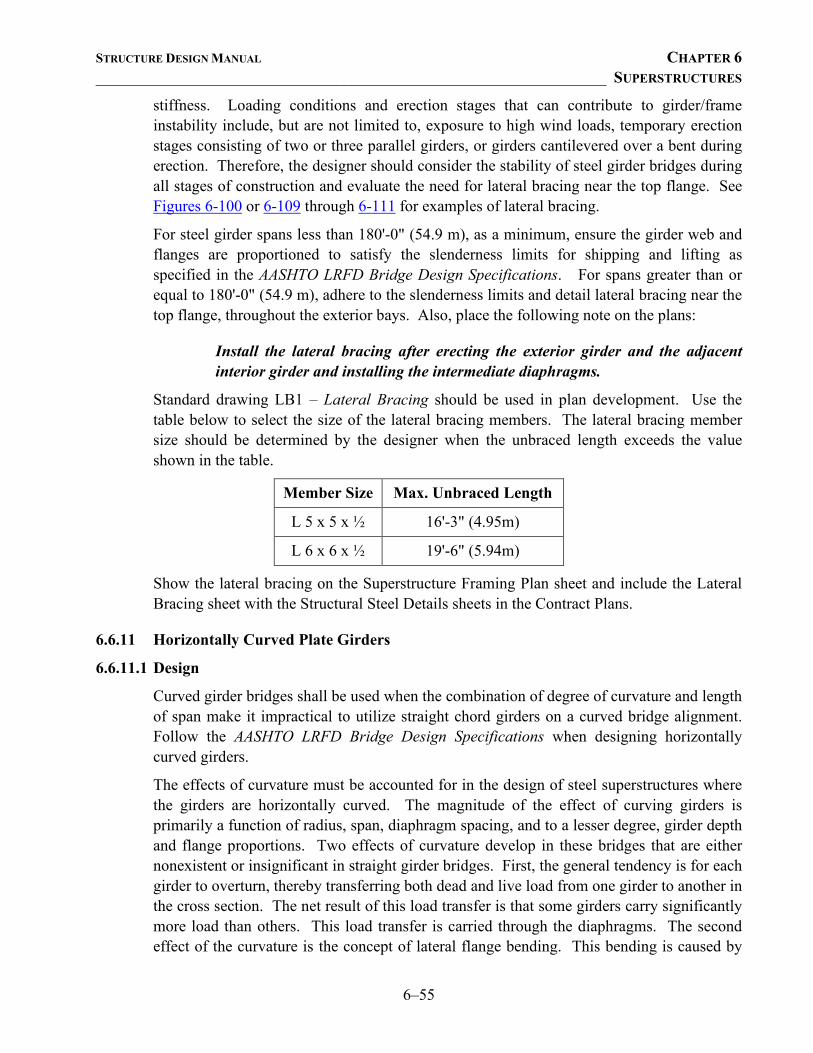
STRUCTURE DESIGN MANUAL CHAPTER 6 ________________________________________________________________ SUPERSTRUCTURES
6–55
stiffness. Loading conditions and erection stages that can contribute to girder/frame instability include, but are not limited to, exposure to high wind loads, temporary erection stages consisting of two or three parallel girders, or girders cantilevered over a bent during erection. Therefore, the designer should consider the stability of steel girder bridges during all stages of construction and evaluate the need for lateral bracing near the top flange. See Figures 6-100 or 6-109 through 6-111 for examples of lateral bracing.
For steel girder spans less than 180'-0" (54.9 m), as a minimum, ensure the girder web and flanges are proportioned to satisfy the slenderness limits for shipping and lifting as specified in the AASHTO LRFD Bridge Design Specifications. For spans greater than or equal to 180'-0" (54.9 m), adhere to the slenderness limits and detail lateral bracing near the top flange, throughout the exterior bays. Also, place the following note on the plans:
Install the lateral bracing after erecting the exterior girder and the adjacent interior girder and installing the intermediate diaphragms.
Standard drawing LB1 – Lateral Bracing should be used in plan development. Use the table below to select the size of the lateral bracing members. The lateral bracing member size should be determined by the designer when the unbraced length exceeds the value shown in the table.
Member Size Max. Unbraced Length
L 5 x 5 x ½ 16'-3" (4.95m)
L 6 x 6 x ½ 19'-6" (5.94m)
Show the lateral bracing on the Superstructure Framing Plan sheet and include the Lateral Bracing sheet with the Structural Steel Details sheets in the Contract Plans.
6.6.11 Horizontally Curved Plate Girders
6.6.11.1 Design
Curved girder bridges shall be used when the combination of degree of curvature and length of span make it impractical to utilize straight chord girders on a curved bridge alignment. Follow the AASHTO LRFD Bridge Design Specifications when designing horizontally curved girders.
The effects of curvature must be accounted for in the design of steel superstructures where the girders are horizontally curved. The magnitude of the effect of curving girders is primarily a function of radius, span, diaphragm spacing, and to a lesser degree, girder depth and flange proportions. Two effects of curvature develop in these bridges that are either nonexistent or insignificant in straight girder bridges. First, the general tendency is for each girder to overturn, thereby transferring both dead and live load from one girder to another in the cross section. The net result of this load transfer is that some girders carry significantly more load than others. This load transfer is carried through the diaphragms. The second effect of the curvature is the concept of lateral flange bending. This bending is caused by
STRUCTURE DESIGN MANUAL CHAPTER 6 ________________________________________________________________ SUPERSTRUCTURES
6–56
torsion in the curved members that is almost completely resisted by horizontal shear in the girder flanges. These bending stresses either compound or reduce the vertical bending stresses.
Bracing of horizontally curved members is more critical than for straight members. Diaphragm and cross-frame members resist forces that are critical to the proper functioning of curved-girder bridges. Since they transmit the forces necessary to provide equilibrium, they are considered primary members as well as the connections. Therefore, diaphragms are shall be designed to carry the total load transferred at each diaphragm location, including their connections to the girders. Refer to the AASHTO LRFD Bridge Design Specifications for diaphragm design.
6.6.11.2 Details
All curved girder bridges shall be designed for composite action. All intermediate diaphragms shall be placed radially and spaced so as to limit the flange edge stresses due to lateral flange bending.
For sharply curved structures, full depth diaphragms shall have connections to the girder webs and flanges that transfer the flange shears to the diaphragm without over stressing the girder web to flange weld. Transverse welds on the girder flanges will be permitted if the allowable stresses are reduced as per the fatigue criteria pertaining to the connection details.
Single-sided stiffeners on horizontally curved girders should be attached to both flanges. When pairs of transverse stiffeners are used on horizontally curved girders, they shall be a tight fit or welded to both flanges. Stiffeners used as connector plates for diaphragms or cross-frames shall be welded to both flanges.
Special consideration must be given to the expansion and girder end rotation characteristics of curved steel member bridges. On a curved steel member bridge, expansion between the fixed and expansion bearings will occur along a chord between the two bearing points. It is necessary to provide expansion bearings that will permit horizontal movement along this chord. Both the fixed and expansion bearings must provide for end rotation about a radial line.
The splices in flanges of curved girders must be designed to carry both the lateral bending stresses as well as vertical bending stresses in the flanges.
Follow the AASHTO LRFD Bridge Design Specifications for the allowable flange tip stress and fatigue stress.
6.7 BEARINGS AND SOLE PLATES
6.7.1 General
Bridge superstructures shall be supported on bearings, which may be fixed or movable as required for the bridge design. Bearings shall be designed in accordance with AASHTO
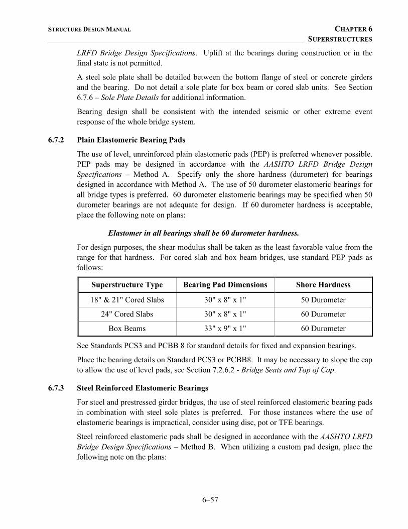
STRUCTURE DESIGN MANUAL CHAPTER 6 ________________________________________________________________ SUPERSTRUCTURES
6–57
LRFD Bridge Design Specifications. Uplift at the bearings during construction or in the final state is not permitted.
A steel sole plate shall be detailed between the bottom flange of steel or concrete girders and the bearing. Do not detail a sole plate for box beam or cored slab units. See Section 6.7.6 – Sole Plate Details for additional information.
Bearing design shall be consistent with the intended seismic or other extreme event response of the whole bridge system.
6.7.2 Plain Elastomeric Bearing Pads
The use of level, unreinforced plain elastomeric pads (PEP) is preferred whenever possible. PEP pads may be designed in accordance with the AASHTO LRFD Bridge Design Specifications – Method A. Specify only the shore hardness (durometer) for bearings designed in accordance with Method A. The use of 50 durometer elastomeric bearings for all bridge types is preferred. 60 durometer elastomeric bearings may be specified when 50 durometer bearings are not adequate for design. If 60 durometer hardness is acceptable, place the following note on plans:
Elastomer in all bearings shall be 60 durometer hardness.
For design purposes, the shear modulus shall be taken as the least favorable value from the range for that hardness. For cored slab and box beam bridges, use standard PEP pads as follows:
Superstructure Type Bearing Pad Dimensions Shore Hardness
18" & 21" Cored Slabs 30" x 8" x 1" 50 Durometer
24" Cored Slabs 30" x 8" x 1" 60 Durometer
Box Beams 33" x 9" x 1" 60 Durometer
See Standards PCS3 and PCBB 8 for standard details for fixed and expansion bearings.
Place the bearing details on Standard PCS3 or PCBB8. It may be necessary to slope the cap to allow the use of level pads, see Section 7.2.6.2 - Bridge Seats and Top of Cap.
6.7.3 Steel Reinforced Elastomeric Bearings
For steel and prestressed girder bridges, the use of steel reinforced elastomeric bearing pads in combination with steel sole plates is preferred. For those instances where the use of elastomeric bearings is impractical, consider using disc, pot or TFE bearings.
Steel reinforced elastomeric pads shall be designed in accordance with the AASHTO LRFD Bridge Design Specifications – Method B. When utilizing a custom pad design, place the following note on the plans:
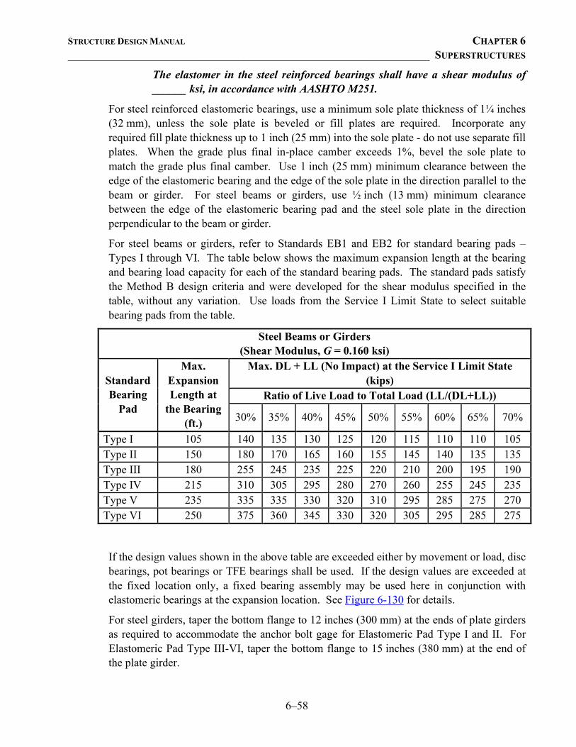
STRUCTURE DESIGN MANUAL CHAPTER 6 ________________________________________________________________ SUPERSTRUCTURES
6–58
The elastomer in the steel reinforced bearings shall have a shear modulus of ______ ksi, in accordance with AASHTO M251.
For steel reinforced elastomeric bearings, use a minimum sole plate thickness of 1¼ inches (32 mm), unless the sole plate is beveled or fill plates are required. Incorporate any required fill plate thickness up to 1 inch (25 mm) into the sole plate - do not use separate fill plates. When the grade plus final in-place camber exceeds 1%, bevel the sole plate to match the grade plus final camber. Use 1 inch (25 mm) minimum clearance between the edge of the elastomeric bearing and the edge of the sole plate in the direction parallel to the beam or girder. For steel beams or girders, use ½ inch (13 mm) minimum clearance between the edge of the elastomeric bearing pad and the steel sole plate in the direction perpendicular to the beam or girder.
For steel beams or girders, refer to Standards EB1 and EB2 for standard bearing pads – Types I through VI. The table below shows the maximum expansion length at the bearing and bearing load capacity for each of the standard bearing pads. The standard pads satisfy the Method B design criteria and were developed for the shear modulus specified in the table, without any variation. Use loads from the Service I Limit State to select suitable bearing pads from the table.
Steel Beams or Girders (Shear Modulus, G = 0.160 ksi)
Standard Bearing
Pad
Max. Expansion Length at
the Bearing (ft.)
Max. DL + LL (No Impact) at the Service I Limit State (kips)
Ratio of Live Load to Total Load (LL/(DL+LL))
30% 35% 40% 45% 50% 55% 60% 65% 70%
Type I 105 140 135 130 125 120 115 110 110 105 Type II 150 180 170 165 160 155 145 140 135 135 Type III 180 255 245 235 225 220 210 200 195 190 Type IV 215 310 305 295 280 270 260 255 245 235 Type V 235 335 335 330 320 310 295 285 275 270 Type VI 250 375 360 345 330 320 305 295 285 275
If the design values shown in the above table are exceeded either by movement or load, disc bearings, pot bearings or TFE bearings shall be used. If the design values are exceeded at the fixed location only, a fixed bearing assembly may be used here in conjunction with elastomeric bearings at the expansion location. See Figure 6-130 for details.
For steel girders, taper the bottom flange to 12 inches (300 mm) at the ends of plate girders as required to accommodate the anchor bolt gage for Elastomeric Pad Type I and II. For Elastomeric Pad Type III-VI, taper the bottom flange to 15 inches (380 mm) at the end of the plate girder.
STRUCTURE DESIGN MANUAL CHAPTER 6 ________________________________________________________________ SUPERSTRUCTURES
6–59
When elastomeric bearings pads are used at expansion ends of steel girders with bearing-to-bearing distances greater than 120 feet (36.58 m), detail grout cans to accommodate placement of anchor bolts. Place the following notes on the plans:
The contractor's attention is called to the following procedure, which may be required by the Engineer, to reset elastomeric bearings due to girder translation and end rotation:
1. Once the deck has cured, the girders shall be jacked then the anchor bolts and elastomeric bearing slots centered as nearly as practical about the bearing stiffener. This operation shall be performed at approximately 60° F (16° C).
2. After centering the elastomeric bearing slots and anchor bolts, the anchor bolts shall be grouted.
The contractor may propose alternate methods, provided details are submitted to the Engineer for review and approval.
When elastomeric bearings pads are used at expansion ends of steel girders with bearing-to-bearing distances less than or equal to 120 feet (36.58 m), place the following notes on the plans:
The contractor's attention is called to the following procedure, which may be required by the Engineer, to reset elastomeric bearings due to girder translation and end rotation:
1. Once the deck has cured, the girders shall be jacked and the elastomeric bearing slots centered as nearly as practical about the bearing stiffener. This operation shall be performed at approximately 60° F (16° C).
The contractor may propose alternate methods, provided details are submitted to the Engineer for review and approval.
In addition, when elastomeric bearings are used at expansion ends of steel girders, place the following note on the appropriate bent or end bent drawing(s):
Epoxy coat the [end] bent cap after adjustments are made to bearings and anchor bolts are grouted.
For prestressed concrete girders, refer to Standards EB3 and EB4 for standard pads – Types II through VII. The table below shows the maximum expansion length at the bearing and bearing load capacity for each of the standard bearing pads. The standard pads satisfy the Method B design criteria and were developed for the shear modulus specified in the table, without any variation. Use loads from the Service I Limit State to select suitable bearing pads from the table.
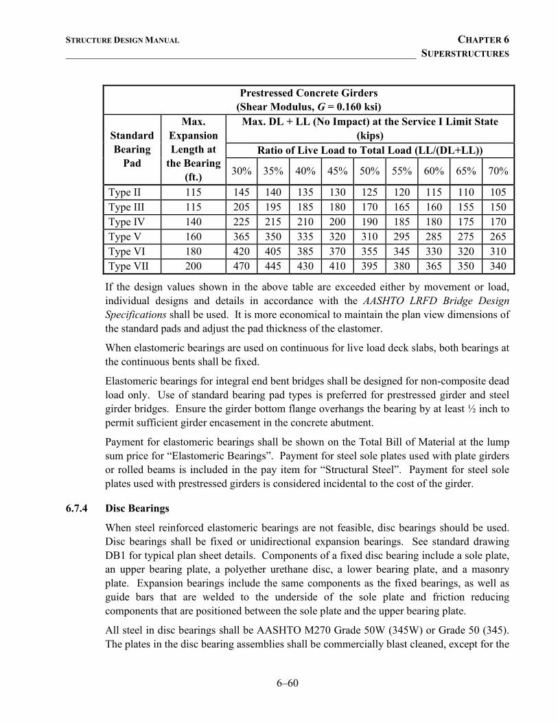
STRUCTURE DESIGN MANUAL CHAPTER 6 ________________________________________________________________ SUPERSTRUCTURES
6–60
Prestressed Concrete Girders (Shear Modulus, G = 0.160 ksi)
Standard Bearing
Pad
Max. Expansion Length at
the Bearing (ft.)
Max. DL + LL (No Impact) at the Service I Limit State (kips)
Ratio of Live Load to Total Load (LL/(DL+LL))
30% 35% 40% 45% 50% 55% 60% 65% 70%
Type II 115 145 140 135 130 125 120 115 110 105 Type III 115 205 195 185 180 170 165 160 155 150 Type IV 140 225 215 210 200 190 185 180 175 170 Type V 160 365 350 335 320 310 295 285 275 265 Type VI 180 420 405 385 370 355 345 330 320 310 Type VII 200 470 445 430 410 395 380 365 350 340
If the design values shown in the above table are exceeded either by movement or load, individual designs and details in accordance with the AASHTO LRFD Bridge Design Specifications shall be used. It is more economical to maintain the plan view dimensions of the standard pads and adjust the pad thickness of the elastomer.
When elastomeric bearings are used on continuous for live load deck slabs, both bearings at the continuous bents shall be fixed.
Elastomeric bearings for integral end bent bridges shall be designed for non-composite dead load only. Use of standard bearing pad types is preferred for prestressed girder and steel girder bridges. Ensure the girder bottom flange overhangs the bearing by at least ½ inch to permit sufficient girder encasement in the concrete abutment.
Payment for elastomeric bearings shall be shown on the Total Bill of Material at the lump sum price for “Elastomeric Bearings”. Payment for steel sole plates used with plate girders or rolled beams is included in the pay item for “Structural Steel”. Payment for steel sole plates used with prestressed girders is considered incidental to the cost of the girder.
6.7.4 Disc Bearings
When steel reinforced elastomeric bearings are not feasible, disc bearings should be used. Disc bearings shall be fixed or unidirectional expansion bearings. See standard drawing DB1 for typical plan sheet details. Components of a fixed disc bearing include a sole plate, an upper bearing plate, a polyether urethane disc, a lower bearing plate, and a masonry plate. Expansion bearings include the same components as the fixed bearings, as well as guide bars that are welded to the underside of the sole plate and friction reducing components that are positioned between the sole plate and the upper bearing plate.
All steel in disc bearings shall be AASHTO M270 Grade 50W (345W) or Grade 50 (345). The plates in the disc bearing assemblies shall be commercially blast cleaned, except for the
STRUCTURE DESIGN MANUAL CHAPTER 6 ________________________________________________________________ SUPERSTRUCTURES
6–61
areas with special facing, and shall be metallized in accordance with the Special Provision for Thermal Sprayed Coatings (Metallization).
Refer to Figure 6-125 for design data such as masonry plate size, anchor bolt gage, and overall bearing height. During design, use this information when computing bridge seat elevations and cap dimensions. Use the anchor bolt gage to check for conflicts with reinforcing steel in the bent cap. To facilitate proper placement of anchor bolts for expansion bearings, detail 4 inch (102 mm) grout cans in the plans.
Use standard drawing DB1 during plan development. Show the total bearing height and the dimensions of the masonry plate. In addition, detail a 1/8 inch (3 mm) preformed bearing pad under the steel masonry plate. Use the following guidelines to orient the masonry plate and other bearing components:
• For all bridges, orient the masonry plate so that the centerline of the plate is normal to the bent cap.
• For fixed or expansion bearings on bridges with straight girders, orient the remaining bearing components parallel to the centerline of the girder.
• For fixed bearings on bridges with curved girders, orient the remaining bearing components parallel to the centerline of the girder.
• For expansion bearings on bridges with curved girders, note that curved girders expand along the chord between the nearest fixed and expansion bearings. Orient the remaining bearing components parallel to the expansion chord for each individual girder. For proper field setting of expansion bearings, include an expansion chord setting table on standard drawing DB1 showing the angle between the centerline of bearing and the expansion chord for each girder. See Figure 6-126 for an example of detailing the expansion chord setting angle.
Disc bearings are designed by the manufacturer to transmit the loads and movement specified in the plans to the substructure. When disc bearings are used, place the unfactored vertical and factored horizontal design loads on standard drawing DB1. The factored horizontal design load for disc bearings is the larger of:
• 15% of the total vertical load (DL + LL w/IM) at the service limit state, or • 25% of the total dead load plus 12.5% of the live load with impact at the service
limit state. The disc bearing manufacturer is responsible for determining the size of the lower bearing plate, disc, upper bearing plate, and sole plate. However, the sole plate is required to extend a minimum of 1 inch (25 mm) beyond both sides of the bottom flange of the girder. Therefore, use the following guidelines to show the sole plate details on standard drawing DB1:
• When disc bearings are used for straight girders, show the length of the sole plate, but not the width or thickness.
STRUCTURE DESIGN MANUAL CHAPTER 6 ________________________________________________________________ SUPERSTRUCTURES
6–62
• When disc bearings are used for curved girders, do not detail the length, width, or thickness of the sole plate. On standard drawing DB1, modify the cut-away plan to show the girder flange is skewed with respect to the sole plate and the minimum edge distance is 1" (25mm), and modify the note that accompanies the sole plate details as such:
Dimensions "L", "W", and "T" shall be determined by the bearing manufacturer. Set dimension "L" such that the minimum edge distance to the girder flange is 1" (25mm).
• Bevel the top of the sole plate to match the final grade of the bottom flange at the location of the bearing and show the percentage slope of the top of the sole plate.
When disc bearings are detailed, place the following notes on the plans:
Sole plates should be welded to girder flanges and anchor bolts should be grouted before falsework is placed.
At all points of support, nuts for anchor bolts shall be finger-tightened plus an additional ¼ turn. The thread of the nut and bolt shall then be burred with a sharp pointed tool.
When welding the sole plate to the girder, use temperature indicating wax pens, or other suitable means, to ensure that the temperature of the bearing does not exceed 250°F (121°C). Temperatures above this may damage the TFE or elastomer.
See Sections 6.7.7 – Sole Plate Details and 6.8 – Anchorage for additional information.
Payment for disc bearings shall be shown on the Total Bill of Material at the lump sum price for “Disc Bearings.”
6.7.5 PTFE Bearings
PTFE, which is also known as TFE, may be used in sliding surfaces of bridge bearings to accommodate translation or rotation. TFE bearings may be used when steel reinforced elastomeric bearings are not feasible, and they shall be designed in accordance with the AASHTO LRFD Bridge Design Specifications.
When TFE bearings are used, refer to Standard TFE1 and Figure 6-129 for typical details. Use 4 inch (102 mm) grout cans at expansion assembly locations. At fixed locations, use a curved sole plate with a 2'-0" (610 mm) radius and a flat masonry plate with a thickness of 1 ¼ in (32 mm), unless the sole plate is beveled or fill plates are required. See Figure 6-130 for details.
Size the TFE pad based on the bearing loads. Limit the compressive stress on the TFE sliding surface to 3000 psi (20.7 MPa) including any stress due to eccentric loading. The
STRUCTURE DESIGN MANUAL CHAPTER 6 ________________________________________________________________ SUPERSTRUCTURES
6–63
contact stress between the PTFE and the mating surface shall be in accordance with the AASHTO LRFD Bridge Design Specifications.
Use a ½ inch (13 mm) minimum clearance between the edge of the TFE pad and the edge of the stainless steel sheet in all directions. The length of the stainless steel sheet in the direction parallel to the girder shall also be based on the anticipated movement due to thermal effects and end rotation, rounded up to the next inch (20 mm). For the temperature setting table and details to be shown on the plans, see Figure 6-124.
For TFE expansion bearing assemblies, all bearing plates shall be galvanized except the plates receiving the TFE pad or stainless steel sheet. The plates receiving the TFE pad or stainless steel sheet shall be commercially blast cleaned and, except for the areas with special facing, shall be painted in accordance with the Special Provisions.
When the grade of the girder at the location of the bearing due to roadway grade and final camber is between 4% and 8%, bevel the top of the curved sole plate 1 inch (25 mm) in 24 inches (610 mm). When the grade of the girder at the location of the bearing is greater than 8%, bevel the top of the curved sole plate to match the grade of the girder. When fill plates are required, place the following note on the plans:
At the Contractors option, fill plates (where used) may be combined with masonry plates.
Place the appropriate notes on the plans:
For TFE Expansion Bearing Assemblies, see Special Provisions.
At fixed points of support, nuts for anchor bolts shall be tightened finger tight and then backed off ½ turn. The thread of the nut and bolt shall then be burred with a sharp pointed tool.
Anchor bolts should be grouted before falsework is placed.
The 1 ½" (38.10 mm) φ pipe sleeve shall be cut from Schedule 40 PVC plastic pipe. The PVC pipe shall meet the requirements of ASTM D1785.
No separate payment will be made for the pipe sleeves. Payment shall be included in the lump sum contract price bid for “TFE Expansion Bearing Assemblies”.
Cambered girder lengths shall be adjusted and bearings are to be placed on the cambered girder so as to be aligned with the anchors after the dead load deflection has occurred. Shop drawings shall be prepared accordingly.
The last note shall be modified and placed on rolled beam spans where the dead load deflection and slope produces a change in length of more than ¼ inch (6 mm).
STRUCTURE DESIGN MANUAL CHAPTER 6 ________________________________________________________________ SUPERSTRUCTURES
6–64
Payment for TFE bearing assemblies shall be shown on the Total Bill of Material at the lump sum price for “TFE Expansion Bearing Assemblies”. Payment for fixed bearing assemblies used in conjunction with TFE expansion bearings shall be included in the pay item for “Structural Steel”.
See Section 6.7.6 – Sole Plate Details for additional information.
6.7.6 Sole Plate Details
With the exception of disc bearings, steel bearing plates used with steel beams or plate girders shall be AASHTO M270 Grade 50W (345W) or Grade 50 (345), or at the designers option Grade 36 (250). In accordance with the Standard Specifications, steel bearing plates for prestressed girders shall be AASHTO M270 Grade 36 (250) and all bearing plates, bolts, nuts and washers used with prestressed girders shall be galvanized. Place the following note on the plans:
All bearing plates shall be AASHTO M270 Grade _______.
For bearing and sole plate surface finish details, see Figure 6-131.
At the fixed end of prestressed girder spans, use 2 7/16" (62 mm) φ holes in the sole plates.
For prestressed girders with integral end bents, do not detail a sole plate or anchor bolts. The embedded plate bears directly on the elastomeric bearing pad. See Figure 6-121 for details.
For steel beams and plate girders with integral end bents, do not detail a sole plate or anchor bolts. The bottom flange will bear directly on the elastomeric bearing pad. See Figure 6-119 for details. Figure 6-120 shows an alternate anchor assembly detail, which may be used when constructing and finishing a bridge seat is not preferred. When finishing a bridge seat is not preferred, consult with the Area Bridge Construction Engineer.
At the fixed end of rolled beam spans, use 1 15/16" (49 mm) φ holes in the sole plates and the elastomeric bearing pads.
At the fixed end of plate girder spans, use 1 15/16" (49 mm) φ holes in the masonry plate and elastomeric pad and 1 15/16" (49 mm) by 2 ¼ inch (57 mm) slots at the top tapered to a 1 15/16" (49 mm) φ hole at the bottom of the sole plate.
At the expansion end for all girder types, the slot size should be determined according to the amount of expansion and end rotation anticipated. See Figure 6-132 for the required slot size.
Show the weld size for the connection between the sole plate and the bottom flange for all bearing types.
The end of prestressed girders, rolled beams or plate girders should extend at least 1 inch (25 mm) beyond the edge of the sole plate.
STRUCTURE DESIGN MANUAL CHAPTER 6 ________________________________________________________________ SUPERSTRUCTURES
6–65
The sole plate shall be field welded to the embedded plate in the prestressed girder with a 5/16 inch (8 mm) minimum groove weld.
For the expansion ends of steel beams or girders on elastomeric bearings, detail a field weld between the sole plates and the flanges. Place the following note on the plans:
When field welding the sole plate to the girder flange, use temperature indicating wax pens, or other suitable means, to ensure that the temperature of the sole plate does not exceed 300ºF (149ºC). Temperatures above this may damage the elastomer.
For disc bearings, detail a field weld between the sole plate and the bottom flange.
6.8 ANCHORAGE For prestressed girder spans, use 2" (50.80 mm) φ anchor bolts set 18 inches (460 mm) into the concrete cap. The anchor bolt gage for sole plates shall be computed as the bottom flange width plus 6 inches (150 mm).
For cored slab spans, provide 1" (25 mm) φ holes in fixed end bearing pads and 2 ½" (64 mm) φ holes in expansion end bearing pads for #6 (#19) dowels. Dowels shall be 1'-6" (460 mm) long set 9 inches (230 mm) into the concrete cap.
For box beams, provide 1¼ " (32 mm) φ holes in fixed end bearing pads and 2½"(64 mm) φ holes in expansion end bearing pads for #8 (#25) dowels. Dowels shall be 2'-3" (685 mm) long set 1'-0" (300 mm) into the concrete cap.
For rolled beam and plate girder spans with elastomeric bearings, use 1 ¾" (44.45 mm) φ anchor bolts, set 18 inches (460 mm) into the concrete cap. The anchor bolt gage for elastomeric bearings shall be as shown on Standards EB1 and EB2.
Anchor bolts are not required at the end bents of girder bridges with integral end bents.
For TFE expansion bearing assemblies, use 1 ½" (38.10 mm) and 1 ¾" (44.45 mm) φ anchor bolts set 15 inches (380 mm) into the concrete cap for the expansion and fixed ends, respectively. The anchor bolt gage for sole plates shall be computed as the bottom flange width plus 5 inches (130 mm). This may be varied to suit special conditions.
For disc bearings, use 1 ½" (38.10 mm) φ anchor bolts set 15 inches (380 mm) into the concrete cap.
The required length of the anchor bolt shall be the required projection plus the embedment length in the concrete cap. Compute the amount of projection of anchor bolts required by adding the thickness of all materials through which the bolt must project plus:
• 2 1/8 inches (54 mm) for 1 ½" (38.10 mm) φ bolts used with disc bearings, rounded to the next 1/8 inch (1 mm).
STRUCTURE DESIGN MANUAL CHAPTER 6 ________________________________________________________________ SUPERSTRUCTURES
6–66
• 2 ¼ inches (60 mm) for 1 ½" (38.10 mm) φ bolts, except when used with disc bearings, and 1 ¾" (44.45 mm) φ bolts rounded up to next ½ inch (10 mm).
• 2 ½ inches (65 mm) for 2" (50.80 mm) φ bolts rounded up to next ½ inch (10 mm). For elastomeric bearings, detail the anchor bolt length on both the applicable EB Standard Drawing and each substructure unit sheet.
Except when detailing disc bearings, if the required projections on a given substructure unit vary by 1 inch (30 mm) or less, show the projection for all bolts as the maximum required on that substructure unit.
6.9 BRIDGE RATING All girders designed in accordance with the AASHTO LRFD Bridge Design Specifications shall be rated in accordance with the AASHTO Manual for Bridge Evaluation.
Initial girder rating is an integral part of the design process. The load and resistance factor rating (LRFR) process for new bridges is summarized in Figure 6-133. The LRFR limit states and load factors shall be as shown in Figure 6-134. See Section 2-2 for variances from the AASHTO Manual for Bridge Evaluation. Where applicable, the allowable stress limits shall be as required for design. See Figure 6-134.
LRFR shall be performed for all applicable strength and service limit states. Perform an inventory and operating rating for the HL-93 design live load and HS-20 truck, and a legal load rating for all of North Carolina's notional legal trucks. The Bridge Management Unit maintains the list of NC legal truck configurations. Bridges on the national highway system (NHS) routes, but are not on the interstate highway system, shall be rated for non-interstate NC legal trucks.
The initial rating for exterior and interior girders shall be archived in the design folder. Acceptable rating factors (RF) shall be at least 1.00. Include a LRFR summary in the contract plans in the location shown in the Plan Assembly Outline (Figure 1-1). The following standard drawings should be used in plan development:
• LRFR1 – “LRFR Summary for Prestressed Concrete Girders & Beams (Interstate Traffic)”
• LRFR2 – “LRFR Summary for Prestressed Concrete Girders & Beams (Non-Interstate Traffic)”
• LRFR3 – “LRFR Summary for Steel Girders (Interstate Traffic)” • LRFR4 – “LRFR Summary for Steel Girders (Non-Interstate Traffic)”
When performing the initial rating, use the same method of analysis as used for design. Provide sufficient information on the bridge analysis to facilitate replication of the LRFR summary. For example, when a refined method of analysis is used for design, as a

STRUCTURE DESIGN MANUAL CHAPTER 6 ________________________________________________________________ SUPERSTRUCTURES
6–67
minimum, provide a table of distribution factors for the design force effects in each span in the LRFR summary.
LRFR is not required for bridge widenings that are not designed in accordance with the AASHTO LRFD Bridge Design Specifications.
STRUCTURE DESIGN MANUAL CHAPTER 7
___________________________________________________________________ SUBSTRUCTURES
7–i
CONTENTS
Chapter 7 ........................................................................................................................................... 7–1
7.1 Substructure Type ................................................................................................................. 7–1
7.2 End Bents .............................................................................................................................. 7–1
7.2.1 General ...................................................................................................................... 7–1
7.2.2 End Bent Caps........................................................................................................... 7–2
7.2.2.1 Dimensions ................................................................................................ 7–2
7.2.2.2 Sloping Caps .............................................................................................. 7–2
7.2.2.3 Cap Clearances........................................................................................... 7–2
7.2.2.4 Cap Reinforcement .................................................................................... 7–3
Flexural Reinforcement ............................................................................. 7–3 Shear Reinforcement.................................................................................. 7–3
Skin Reinforcement ................................................................................... 7–3 Miscellaneous Reinforcement.................................................................... 7–3
7.2.3 End Bent Backwalls .................................................................................................. 7–4
7.2.4 End Bent Wingwalls ................................................................................................. 7–4
7.2.5 End Bent Piles ........................................................................................................... 7–5
7.2.5.1 Brace Piles ................................................................................................. 7–6
7.2.6 End Bent Detailing .................................................................................................... 7–6
7.2.6.1 Layout ........................................................................................................ 7–6
7.2.6.2 Bridge Seats and Top of Cap ..................................................................... 7–6
7.2.6.3 Anchor Bolts and Dowels .......................................................................... 7–7
7.2.6.4 Construction Joints..................................................................................... 7–7
7.2.6.5 Acute Corners ............................................................................................ 7–7
7.2.6.6 Epoxy Protective Coating .......................................................................... 7–8
7.2.7 End Bents with Walls................................................................................................ 7–8
7.2.8 Temporary Drainage ................................................................................................. 7–8
7.3 Integral End Bents................................................................................................................. 7–8
7.3.1 General ...................................................................................................................... 7–8
7.3.2 Diaphragms ............................................................................................................... 7–9
7.3.3 Piles ........................................................................................................................... 7–9
7.3.4 Wingwalls ................................................................................................................. 7–9
7.3.5 Approach Slabs ....................................................................................................... 7–10
7.4 Bents ................................................................................................................................... 7–10
7.4.1 General .................................................................................................................... 7–10
7.4.2 Bent Caps ................................................................................................................ 7–11
7.4.2.1 Dimensions .............................................................................................. 7–11
7.4.2.2 Sloping Caps ............................................................................................ 7–12
7.4.2.3 Cap Clearances......................................................................................... 7–12
7.4.2.4 Cap Reinforcement .................................................................................. 7–12
Flexural Reinforcement ........................................................................... 7–13 Shear Reinforcement................................................................................ 7–13 Skin Reinforcement ................................................................................. 7–13
STRUCTURE DESIGN MANUAL CHAPTER 7
___________________________________________________________________ SUBSTRUCTURES
7–ii
Miscellaneous Reinforcement.................................................................. 7–13
7.4.3 Bent Detailing ......................................................................................................... 7–13
7.4.3.1 Plan Layout .............................................................................................. 7–13
7.4.3.2 Bridge Seats and Top of Cap ................................................................... 7–14
7.4.3.3 Epoxy Protective Coating ........................................................................ 7–14
7.4.3.4 Anchor Bolts and Dowels ........................................................................ 7–14
7.4.3.5 Construction Joints................................................................................... 7–15
7.4.4 Pile Bents ................................................................................................................ 7–15
7.4.4.1 Piles .......................................................................................................... 7–15
Pile Resistance ......................................................................................... 7–16 Steel Piles ................................................................................................. 7–16
Prestressed Concrete Piles ....................................................................... 7–17
Composite Piles ....................................................................................... 7–17
7.4.5 Post and Beam Bents .............................................................................................. 7–17
7.4.5.1 Columns ................................................................................................... 7–17
Column Diameter ..................................................................................... 7–17 Column Spacing ....................................................................................... 7–18 Column Reinforcement ............................................................................ 7–18
Battered Columns .................................................................................... 7–18 Construction Joints .................................................................................. 7–19
7.4.5.2 Drilled Shafts ........................................................................................... 7–19
Drilled Shaft Reinforcement .................................................................... 7–19 Drilled Shaft Notes .................................................................................. 7–19
7.4.5.3 Footings.................................................................................................... 7–21
Spread Footings ....................................................................................... 7–22
Pile Footings ............................................................................................ 7–22 Drilled Pier Footings ................................................................................ 7–22
Scour ........................................................................................................ 7–22 7.5 Foundation Excavation ....................................................................................................... 7–23
7.6 Pier Protection ..................................................................................................................... 7–23
7.6.1 Shoulder Bents ........................................................................................................ 7–23
7.6.2 Interior Bents .......................................................................................................... 7–24
7.6.3 Railroad Overheads ................................................................................................. 7–24
7.7 Rock Embankments ............................................................................................................ 7–25
STRUCTURE DESIGN MANUAL CHAPTER 7
___________________________________________________________________ SUBSTRUCTURES
7–1
CHAPTER 7
SUBSTRUCTURES
7.1 SUBSTRUCTURE TYPE
The primary function of the substructure is to transmit loads from the superstructure to the
foundation. Foundations are the structural elements that transfer vertical, lateral, and
rotational loads into the soil by soil-structure interaction. Soil-structure interaction is
influenced by the type and geometry of the foundation and the characteristics of the
surrounding soil. The foundation spreads concentrated loads over a sufficient area to
provide adequate bearing capacity and limit movement.
The substructure and foundation types employed throughout the State are influenced by the
variety of subsurface conditions present. Collaborate with the Geotechnical Engineering
Unit and Hydraulic Design Unit (for bridges over waterways) to determine a suitable
foundation type, which will be conveyed in the Foundation Recommendations. All bridge
substructures shall be designed in accordance with the AASHTO LRFD Bridge Design
Specifications.
In addition, all bridges shall be assigned to one of four seismic zones. The seismic hazard in
North Carolina is characterized by Seismic Zones 1 and 2. Refer to Figure 2-1 to assign the
preliminary seismic zone to a bridge site. Seismic analysis is not required for multi-span
bridges assigned to Seismic Zone 1 or for single span bridges, regardless of seismic zone.
However, provide seismic detailing such as the minimum girder support length and anchorage
at each end bent, as specified in the LRFD specifications. For multi-span bridges in Seismic
Zone 2, see Section 7.4 - Bents.
For substructures in Corrosive Sites, see Chapter 12.
For information on structural concrete, refer to Section 3-2.
7.2 END BENTS
7.2.1 General
End bents function as a foundation for the bridge superstructure and as an earth retaining
structure for the roadway approaches, and should be sized to resist structural and soil
bearing failure. End bents should also be sized to ensure stability against overturning and
sliding.
End bents typically consist of a reinforced concrete cap and backwall founded on steel H-
piles. When site conditions do not permit end bents on H-piles, other foundation types,
such as prestressed piles, spread footings and micropiles may be considered.
For bridges over highways and railroads, the end slope at the end bents shall be graded in a
manner that provides a 1'-0" (300 mm) minimum berm width, 1'-0" (300 mm) above the
STRUCTURE DESIGN MANUAL CHAPTER 7
___________________________________________________________________ SUBSTRUCTURES
7–2
bottom of the 4'-0" deep end bent cap as shown in Figure 7-15a. For bridges over streams
or waterways, the end slopes and rip rap protection shall provide berm widths as indicated
in Figures 11-1 through 11-3.
7.2.2 End Bent Caps
7.2.2.1 Dimensions
For end bents on tangent alignments, use Figures 7-3 through 7-8 to compute the cap
layout. These figures should be modified for curved or spiral alignments. Show the control
line for the end bent in the plan layout.
The typical end bent cap size shall be 2'-9" (840 mm) wide and 4'-0" (1.22 m) deep. For
girder bridges, consider reducing the bridge length by utilizing deeper end bents. Use
Figure 7-23a to determine the width of the cap based on the pile type and size. Note that
the girder flange, sole plate, bearing, anchor bolt gage, and reinforcement clearances
described in Section 7.2.2.3 – Cap Clearances may increase the cap width.
When 4'-0" (1.22 m) deep caps are not feasible, e.g. for low water bridges or locations
where excavating or raising the grade is not desirable or economical, 2'-6" (760 mm) deep
end bent caps may be used. Detail the berm 1'-6" (450 mm) above the bottom of the 2'-6"
deep cap as shown in Figure 7-15 and detail the piles embedded 1'-0" (300 mm) into the
cap.
7.2.2.2 Sloping Caps
Detail a level bottom of cap unless the cap depth increases by more than 15 inches
(380 mm) between each end. In that case, consider sloping the bottom of the cap along its
length to reduce concrete quantities and detail the same stirrup height throughout the length
of the end bent cap. When the bottom of the cap is sloped, slope the top of the end bent cap
to match the bottom of cap and ensure the minimum cap depth is satisfied at all sections.
Also, see Section 7.2.6.2 – Bridge Seats and Top of Cap for additional guidance.
7.2.2.3 Cap Clearances
Follow these guidelines when determining the end bent cap width:
• For steel superstructures, the distance from the side face or step of end bent cap to
the centerline of the anchor bolt shall not be less than 5½ inches (140mm), nor shall
the distance to any edge or corner of an elastomeric bearing or masonry plate be less
than 2 ½ inches (65 mm).
• For prestressed girder superstructures, the distance from the side face or step of the
end bent cap to the centerline of the anchor bolt shall not be less than 5 ½ inches
(140 mm), nor shall the distance to the elastomeric bearing be less than 2 ½ inches
(65 mm).
In addition, ensure the minimum clearance between the end of the girder and the end bent
backwall is satisfied, as required in Sections 6.3.1.3 or 6.6.2. Top flange plates of steel
STRUCTURE DESIGN MANUAL CHAPTER 7
___________________________________________________________________ SUBSTRUCTURES
7–3
superstructures may be clipped when the bridge skew is less than 60o or more than 120o.
See Section 6.6.6 for additional information.
7.2.2.4 Cap Reinforcement
Design the cap to resist structural failure at the strength limit state. For deep caps, a
significant amount of the load from the superstructure may be transferred to the foundation
by compression struts joining the load and the pile support. Therefore, consider deep beam
theory (e.g. employ a strut and tie model) rather than the traditional flexural beam theory
when employing deep caps.
Flexural Reinforcement
For typical cap dimensions as described above, the minimum number and size of flexural
reinforcement bars for the top and bottom of the end bent cap shall be 4 - #9 (#29) bars for
cap widths less than 3'-0" (910mm). For each additional 1'-0" (300mm) of cap width,
increase the minimum reinforcement by one additional #9 (#29) bar.
Follow these guidelines when detailing steel in the top of end bent caps:
• When the bottom of the end bent cap is level, detail the top reinforcing steel
horizontal, as shown in Figure 7-2. If the distance from the centerline of the bars to
the top of the cap exceeds 6 inches (150 mm), maintain the location of the main
flexural reinforcing steel and provide additional #4 (#13) bars – shadow steel, to
match the number of top bars, as shown in the figure. If this distance is greater than
12 inches (305 mm), raise the reinforcing steel and provide a full lap splice.
• When the bottom of the end bent cap is sloped, the top steel should be placed
parallel to the bottom of the cap. Detail the stirrups with a clear distance of 2 inches
(50 mm) below the critical point along the top of cap so that the stirrups will be
uniform throughout the length of the cap. Where the distance from the centerline of
the bar to the top of the cap exceeds 7 inches (180 mm) provide additional #4 (#13)
horizontal bars to match the number of main bars in the top of the cap. See Figure
7-2 for details.
Shear Reinforcement
Stirrups between piles shall form enclosed hoops using one ‘U’ shaped stirrup and one
horizontal stirrup near the top of the cap at each location. Transverse reinforcement shall
be #4 (#13) or #5 (#16) stirrups. The maximum spacing of stirrups shall be 12 in.
(300mm).
Skin Reinforcement
Provide skin reinforcement along both side faces of all end bent caps. See Section 2.3 for
variations from the LRFD specifications.
Miscellaneous Reinforcement
Detail 4 or 5 - #4 (#13) ‘B’ bars longitudinally at equal spaces above each row of piles and
#4 (#13) ‘B’ bars at 4' (1.2 m) centers placed normal to the length of cap. Also, for each
STRUCTURE DESIGN MANUAL CHAPTER 7
___________________________________________________________________ SUBSTRUCTURES
7–4
foot of pile embedment, detail 2 - #4 (#13) circular ‘S’ hoops around each pile in a single
row system and 3 pairs of #4 (#13) rectangular ‘S’ bars around each pile in a double row
system. See Figures 7-23a and 7-24a for details.
7.2.3 End Bent Backwalls
Detail backwalls for all bridge types, except cored slabs. Design the backwall to support
the approach slab and retain the bridge approach fill. The height of backwall is based on
the superstructure depth. See Figure 7-12 for backwall details. The standard backwall
reinforcing steel is sufficient for short to moderate depth superstructures (≤ 6'-0"). For
superstructures deeper than 6'-0", design the backwall to resist active/passive lateral earth
loads on the fill face.
Detail a permitted horizontal construction joint between the backwall and the end bent cap.
Extend the construction joint through the wings level with the cap. Detail the ‘K’ bars for
the entire length of the backwall. Match the ‘H’ bars in the wing to the ‘K’ bars in the
backwall as applicable. See Figures 7-13 and 7-14 for details.
In the plans, show the elevations on the top of the backwall along the fill face. Provide
elevations at the left side, at the centerline of survey or the grade point, and at the right side.
Also, show elevations at all crown breaks.
Detail oversized blockouts for water or sewer utilities passing through the backwall, when
applicable. Provide a blockout sized 4" (100 mm) larger than the utility pipe diameter.
Place the following note on the plans:
Center utility in blockout and fill annular space around utility pipe with joint
filler in accordance with Standard Specification Article 1028-1.
7.2.4 End Bent Wingwalls
Detail turned back wings parallel to the superstructure for all end bents. They should be
of sufficient length to retain the approach roadway embankment and provide protection
against erosion. The bottom of wingwalls may be tapered to reduce weight. For bridges
with integral end bents see Section 7.3 – Integral End Bents for additional information on
wingwalls.
Locate the outside edge of the wingwalls 3 feet (measured perpendicular) from the outside
edge of superstructure. Use Figure 7-15 or Figure 7-15a when computing the required
length of wingwalls. Calculate the turned back wingwall length using a 1'-0" berm width,
regardless of the computed berm width of the bridge. The minimum length of the
wingwalls is 7’-0” for 2'-6" and 4'-0" deep end bent caps. For cored slab and box beam
bridges, do not detail wingwall brace piles, regardless of wingwall length. For girder
bridges, a brace pile may be required based on the wingwall aspect ratio. Refer to Figure 7-
19 to determine if a brace pile is required. When required, detail the brace pile one-third
(1/3) of the wingwall length from the end of the wingwall. See Figure 7-16a for brace pile
details. Figure 7-13 shows reinforcing steel for wingwalls on 2'-6" (760 mm) end bent
STRUCTURE DESIGN MANUAL CHAPTER 7
___________________________________________________________________ SUBSTRUCTURES
7–5
caps, and Figures 7-13a and 7-19 show reinforcing steel for wingwalls on 4'-0" (1.22 m)
end bent caps. Ensure the connection between that wingwall and cap is adequately
reinforced.
Detail the top of the wingwalls level, as shown in Figure 7-14. Figure 7-14 also suggests a
method for detailing sloped top of wings when necessary. In general, set the top-of-wing
elevations at the outside edge of the approach slab to match the top of the curb or sidewalk,
and detail the bottom of wings level with the bottom of cap. Also, detail 1 inch (25 mm)
expansion joint material in the vertical joint between the backwall and the outside edge of
the approach slab.
To facilitate slip forming the barrier rail or parapet, detail a blockout as shown in Figures
7-17 and 7-18. Reinforcing steel in the blockout may be bent as necessary during slip
forming the barrier rail. Concrete shall be placed in the blockout after the barrier rail or
parapet and end post are cast.
For bridges with reinforced bridge approach fill which is retained by wingwalls, place the
following note on the end bent sheet:
Install the 4" (102 mm) drain pipe through the wingwall as required for
Reinforced Bridge Approach Fills, see the Roadway plans. Reinforcing steel in
the wingwall may be shifted as necessary to clear the drain pipe.
7.2.5 End Bent Piles
End bents are typically supported on vertical piles. However, brace piles may be included
to resist lateral loads in excess of the lateral resistance of vertical piles and prevent
overturning. Piles transfer loads to deeper suitable strata and may function through skin
friction and/or through end bearing.
The Geotechnical Engineering Unit will convey the pile type and size in the Foundation
Recommendations. Coordinate with the Geotechnical Engineering Unit to optimize the
number of piles and pile tonnage. Based on the pile driving conditions and the size of crane
required to drive the piles, discuss with the Geotechnical Engineering Unit whether it is
more economical to use low tonnage piles or high tonnage piles
End bents shall be supported by a minimum of five piles and the pile spacing shall not
exceed 10'-0" (3.05 m) or be less than 30 in. (760 mm) or 2½ times the pile width or
diameter, whichever is greater. Space the vertical and brace piles uniformly about the
centerline of the cap. See Section 2.3.15 for the minimum pile embedment into the end
bent cap.
For end bents supported on steel piles, detail a concrete collar for each vertical and braced
pile as shown in the Figures 7-23 and 7-24, except when a wall is located in front of the end
bent and the piles are surrounded by select backfill. A concrete collar is not required for
wingwall brace piles.
STRUCTURE DESIGN MANUAL CHAPTER 7
___________________________________________________________________ SUBSTRUCTURES
7–6
When pipe piles are used in end bents, the embedment length of the pile into the cap shall
be filled with concrete. Use details similar to Figure 7-25.
7.2.5.1 Brace Piles
When required, brace piles are to be battered 3 inches per foot (250 mm per 1000 mm).
Note that the Foundation Recommendations may require brace piles where less that 15 ft
(4.57m) of pile penetration is anticipated.
The maximum spacing between brace piles shall be 25'-0" (7.62 m). See Figure 7-23 for
details at end bents with a single row of piles and Figure 7-24 for end bents with a double
row of piles.
Brace piles should not be used on bridges with a wall or sheet piling in front of the end bent
cap. If the lateral resistance of the vertical piles is insufficient to resist lateral earth loads
and prevent overturning or sliding, provide earth reinforcement straps which are attached to
the end bent backwall, to resist the excess lateral load. The straps shall be similar to those
used for the wall system. Compute the excess lateral load to be resisted by the straps and
coordinate with the Geotechnical Engineering Unit to develop the plan details showing the
straps for the lateral load that must be resisted.
7.2.6 End Bent Detailing
7.2.6.1 Layout
Show plan and elevation views of the end bent. In the plan layout, show the following:
• Control line (fill face), and survey or control line,
• Work point and workline,
• Centerline of piles and centerline bearing
Provide all end bent dimensions as measured from the fill face, work point or workline. In
the elevation layout, show all substructure elevations to two decimal places.
7.2.6.2 Bridge Seats and Top of Cap
For girder bridges, detail end bent bridge seats as shown in Figure 7-9. When computing
bridge seat elevations account for the total bearing assembly depth, which includes the
thicknesses of the elastomeric bearing pad and sole plate. When bearings with a steel
masonry plate are used, note that the bearing assembly typically includes a 3/16 inch (5 mm)
preformed pad that is placed between the masonry plate and the concrete cap.
Slope the top surface of end bent caps, between bridge seats, away from the backwall / fill
face, as shown in Figure 7-9.
In general, end bent caps for cored slab and box beam bridges should be level. However, if
the roadway has a normal crown or constant cross-slope, a crowned or sloped bent cap
may be detailed. When sloping the top of cap for normal crown sections, two or three units
shall be level in the middle of the typical section. Consider sloping the top of cap for
STRUCTURE DESIGN MANUAL CHAPTER 7
___________________________________________________________________ SUBSTRUCTURES
7–7
normal crown sections if the asphalt depth exceeds 8" if the units remain level. When the
top of the cap is sloped for a normal crown section, place the following note on the plans.
Grout the shear keys between the level and sloped cored slab (or box beam)
units (i.e. shear keys at break points in the cap) prior to tensioning the
transverse strands.
To facilitate fit up and proper seating, transversely slope all caps the same. For box beams
and cored slabs with sloped caps, show the cap slope rate (%) on the plans. See Sections
6.4.1 and 6.4.2 for additional information.
To accommodate the use of plain, level bearing pads on cored slab and box beam
structures, it may be necessary to slope the bridge seats along the bridge gradeline to
account for grade and slab camber. For flat grades, note that the camber alone may
necessitate detailing sloped seats. Do not slope bridge seats if the difference in seat
elevations is less than ½" (13mm). When bridge seats are sloped along the bridge
gradeline, carefully consider constructibility and proper seating of cored slab or box beam
units. Do not detail different slopes on the same bent cap. Also, do not detail bridge seats
at the end of cored slab or box beam spans that are sloped in opposing directions, even if
the grade conditions and camber predictions suggest doing so. Whenever possible,
coordinate with the Roadway Design Unit to mitigate or eliminate this condition.
7.2.6.3 Anchor Bolts and Dowels
Detail anchor bolts or dowels as required for the superstructure. When necessary also detail
grout cans. See Chapter 6 for additional information on anchor bolts, dowels, and grout
cans.
7.2.6.4 Construction Joints
Detail a construction joint in the end bent cap when the cap length exceeds 90 feet (30 m).
Locate the construction joint within 2 - 3 feet (1 m) of a pile. Detail a shear key in the cap
at the construction joint.
For staged construction, detail a shear key in the cap at the construction joint. Whenever
possible, detail lap splices for the main cap reinforcement and skin reinforcement. Use of
reinforcing steel mechanical couplers is permitted when lap splices are not feasible.
For stage-constructed end bent caps on skews, since the construction joint in the cap and
backwall between stages is detailed normal to the cap, verify the staged length of cap and
backwall will adequately support the approach slab and the backfill under the approach
slab.
7.2.6.5 Acute Corners
For bridges with skews 60 or ≥ 120, chamfer the end bent cap and wing corners in
accordance with Figure 7-10, and ensure all minimum clearances and edge distances are
maintained.
STRUCTURE DESIGN MANUAL CHAPTER 7
___________________________________________________________________ SUBSTRUCTURES
7–8
7.2.6.6 Epoxy Protective Coating
End bent caps for girder bridges shall receive an epoxy protective coating in accordance
with the Standard Specifications. The epoxy protective coating shall not be applied to the
area under elastomeric bearings. For bearings with steel masonry plates, the Contractor
may, but is not required to, coat the areas under the bearings.
End bent caps for prestressed concrete cored slab and box beam structures shall not receive
an epoxy protective coating.
When an epoxy protective coating is required, place the following notes on the end bent
plan sheet:
The top surface areas of the end bent caps shall be cured in accordance with
the Standard Specifications, except the Membrane Curing Compound Method
shall not be used.
Backwall shall be placed before applying the Epoxy Protective Coating.
Do not detail an epoxy protective coating on the top of the backwall.
7.2.7 End Bents with Walls
Mechanically stabilized earth (MSE), sheet pile abutments and other wall types may be
used to reduce or balance span lengths, eliminate short end spans, mitigate skew, and
reduce right-of-way, utility, or environmental impacts. For more information, see Chapter
12 – Retaining walls.
Detail sheet piles in abutment walls to be galvanized, except in locations subject to tidal
flow. For tidal flow locations the sheet piles shall be metallized. Indicate the type of
coating required in the plan notes and Bill of Material.
7.2.8 Temporary Drainage
Temporary drainage details shall be shown on the plans for all end bents. For details and
notes to be shown on the plans, see Figure 7-11. The figure is drawn to show normal crown
and should be modified for superelevated structures or other conditions on a project specific
basis.
7.3 INTEGRAL END BENTS
7.3.1 General
Integral end bents are those where the superstructure is cast into an end bent concrete
diaphragm or abutment that serves the purpose of the end bent backwall. There is no
expansion joint in the bridge deck at the end bent, and the end bent diaphragm is rigidly
STRUCTURE DESIGN MANUAL CHAPTER 7
___________________________________________________________________ SUBSTRUCTURES
7–9
connected to the pile cap. Foundations for integral end bents utilize a single row of vertical
piles, oriented for bending about the strong axis, to support the end bent.
Detail integral end bents for girder bridges that meet the following geometric criteria:
• Straight girders on tangent or curved alignments.
• Skews between 70o and 110o, i.e. (70o ≤ skew ≤ 110o).
• Vertical grade ≤ 5%.
• Girder height shall not exceed 6 ft. (1.83m)
• Total bridge length shall not exceed:
• 300 ft. (91.44m) for steel girder superstructures.
• 400 ft. (121.92m) for prestressed concrete girder superstructures.
Integral end bents may be detailed for bridges with total lengths exceeding the above limits
if a joint is detailed at an interior bent location such that the length of bridge between the
end bent and the joint satisfies the length limits.
7.3.2 Diaphragms
Figures 6-119 through 6-123 provide integral end bent details for steel girder and concrete
girder superstructures. The end bent diaphragm is cast monolithically with the end section
of the bridge deck using Class AA concrete. Detail the edges of the end bent diaphragm to
match the outside edges of the superstructure. Do not extend the end bent diaphragm the
full length of the end bent cap.
7.3.3 Piles
Detail only vertical piles; brace piles are not permitted. Ensure the piles are at least 10 ft. in
length to provide sufficient embedment. When the Geotechnical Engineering Unit requires
drilled-in piles (pile excavation) for sites with high rock, dense material, or cohesive soils,
provide prebored holes as necessary to allow for adequate pile lengths. After the piles are
installed, provide 3 feet of concrete or grout at the bottom of each hole to establish fixity
and provide Class II or III select material for the remaining depth of hole to allow
movement. Adhering to the criteria prescribed in Section 7.3.1 and detailing piles as
suggested above will limit the need to analyze and design the piles to resist longitudinal
superstructure movements.
Detail Class A concrete for the concrete cap encasing the piles.
7.3.4 Wingwalls
The layout and wingwall length shall be determined in a manner similar to non-integral end
bents, except wingwall brace piles are not permitted. However, the bottom of integral end
bent wingwalls may be tapered to reduce weight. See Section 7.2.4 – End Bent Wingwalls.
STRUCTURE DESIGN MANUAL CHAPTER 7
___________________________________________________________________ SUBSTRUCTURES
7–10
The section of wingwalls below the horizontal construction joint shall be Class A concrete
and shall be cast monolithically with the concrete cap encasing the piles. The section of
wingwalls above the horizontal construction joint shall be Class A concrete and cast
separate from the end bent diaphragm and end section of bridge deck near the integral end
bent.
7.3.5 Approach Slabs
Determine the required length of approach slab in a manner similar to that for non-integral
end bent bridges. The approach slab shall be supported on a blockout detailed in the
integral end bent diaphragm. Alternatively, the approach slab may be cast monolithically
with the end bent diaphragm and the end section of bridge deck near the integral end bent.
Use BAS5 – "Bridge Approach Slab for Integral Abutment" when preparing plans.
7.4 BENTS
7.4.1 General
Bents function as a foundation for multi-span bridge superstructures and should be sized to
structurally resist applied loads. Bents shall be designed to preclude soil bearing failure and
to ensure deflections are within acceptable tolerances.
Bents typically consist of a reinforced concrete cap founded on:
• Steel H-piles or pipe piles,
• Prestressed concrete piles
• Reinforced concrete columns on drilled shafts, footings on piles or spread footings.
Bent caps shall typically be constructed with cast-in-place concrete. Precast caps may be
considered for accelerated construction and/or low impact bridge replacement projects
using other precast elements, such as cored slabs supported on pile bents. Consider use of
precast bridge elements on bridges with limited clearance above the normal water surface,
where use of cast-in-place concrete is difficult.
Pile bents (precast or cast-in-place caps on prestressed or steel piles) are preferred for
stream crossings and/or short span bridges. Post and beam bents on pile footings or spread
footings are preferred for grade separations, and post and beam bents on drilled shafts
(drilled piers) may be used when other bent types are not feasible.
Single column piers, commonly referred to as hammerhead piers, may be used when
conditions limit using standard bent types. Other non-standard bent types, such as integral
bents or post-tensioned bent caps, may only be used with approval. Coordinate with the
Roadway Design Unit when requesting a revision to the grade and/or alignment to prevent
the need for non-standard bent types.
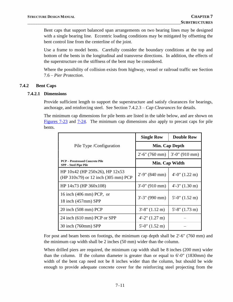
STRUCTURE DESIGN MANUAL CHAPTER 7
___________________________________________________________________ SUBSTRUCTURES
7–11
Bent caps that support balanced span arrangements on two bearing lines may be designed
with a single bearing line. Eccentric loading conditions may be mitigated by offsetting the
bent control line from the centerline of the joint.
Use a frame to model bents. Carefully consider the boundary conditions at the top and
bottom of the bents in the longitudinal and transverse directions. In addition, the effects of
the superstructure on the stiffness of the bent may be considered.
Where the possibility of collision exists from highway, vessel or railroad traffic see Section
7.6 – Pier Protection.
7.4.2 Bent Caps
7.4.2.1 Dimensions
Provide sufficient length to support the superstructure and satisfy clearances for bearings,
anchorage, and reinforcing steel. See Section 7.4.2.3 – Cap Clearances for details.
The minimum cap dimensions for pile bents are listed in the table below, and are shown on
Figures 7-23 and 7-24. The minimum cap dimensions also apply to precast caps for pile
bents.
Pile Type /Configuration
Single Row Double Row
Min. Cap Depth
2'-6" (760 mm) 3'-0" (910 mm)
PCP – Prestressed Concrete Pile
SPP – Steel Pipe Pile Min. Cap Width
HP 10x42 (HP 250x26), HP 12x53
(HP 310x79) or 12 inch (305 mm) PCP 2'-9" (840 mm) 4'-0" (1.22 m)
HP 14x73 (HP 360x108) 3'-0" (910 mm) 4'-3" (1.30 m)
16 inch (406 mm) PCP, or
18 inch (457mm) SPP 3'-3" (990 mm) 5'-0" (1.52 m)
20 inch (508 mm) PCP 3'-8" (1.12 m) 5'-8" (1.73 m)
24 inch (610 mm) PCP or SPP 4'-2" (1.27 m) –
30 inch (760mm) SPP 5'-0" (1.52 m) –
For post and beam bents on footings, the minimum cap depth shall be 2'-6" (760 mm) and
the minimum cap width shall be 2 inches (50 mm) wider than the column.
When drilled piers are required, the minimum cap width shall be 8 inches (200 mm) wider
than the column. If the column diameter is greater than or equal to 6'-0" (1830mm) the
width of the bent cap need not be 8 inches wider than the column, but should be wide
enough to provide adequate concrete cover for the reinforcing steel projecting from the
STRUCTURE DESIGN MANUAL CHAPTER 7
___________________________________________________________________ SUBSTRUCTURES
7–12
column into the cap. Always detail a column above the drilled shaft; do not extend the
drilled shaft to the bottom of the cap.
For hammerhead bents, detail caps that are 4 inches (100 mm) wider than the column. Caps
for hammerhead bents will typically have a variable depth, as required by design. While
hammerhead bents are sometimes selected where aesthetics are important, do not detail
caps with curve ends. For bridges with multiple hammerhead bents, detail the same slopes
on the caps to facilitate reuse of the formwork and provide aesthetic uniformity.
Provide sufficient depth and width to support the superstructure and satisfy clearances for
bearings, anchorage and reinforcing steel. See Section 7.4.2.3 – Cap Clearances for
details.
Other considerations that could influence cap dimensions may include maintenance
operations. For example, when it is necessary to lift steel and prestressed girder spans for
repair, maintenance forces typically use a hydraulic jack placed under the bent diaphragm.
To accommodate this operation on severely skewed bridges, consideration shall be given to
providing a minimum edge distance of 2 ½ inches (65 mm) to the edge of the jacking base
plate. The jack base plate is usually 12 inches (305 mm) by 9 ½ inches (240 mm).
Typically the jack is placed such that the 9 ½ inch (240 mm) dimension is normal to the
centerline of the cap.
7.4.2.2 Sloping Caps
Guidelines for sloping bent caps are similar to those for end bents; see Section 7.2.2.2 –
Sloping Caps. When the top of the bent cap is sloped to match the bottom of cap, ensure
the minimum cap depth is satisfied at all sections.
7.4.2.3 Cap Clearances
Anchor bolt and bearing clearances for bents are similar to the requirements for end bents;
see Section 7.2.2.3 – Cap Clearances.
In addition, follow these guidelines when determining the bent cap length:
• For steel superstructures, the length of interior bent caps should provide a minimum
of 9 inches (230 mm) from the edge or corner of the bearing plate to the end of the
cap.
• For prestressed concrete girder superstructures, the length of interior bent caps
should provide a minimum of 9 inches (230 mm) from the anchor bolt to the end of
the cap.
• For cored slab and box beam structures, the bent cap length shall extend at least
1'-0" (300 mm) beyond the edge of the exterior unit. See Figure 7-1 for details.
7.4.2.4 Cap Reinforcement
Design the cap to resist structural failure at the strength limit state.
STRUCTURE DESIGN MANUAL CHAPTER 7
___________________________________________________________________ SUBSTRUCTURES
7–13
Flexural Reinforcement
Minimum flexural reinforcement for bent caps is similar to end bents; see Section 7.2.2.4 –
Cap Reinforcement.
The guidelines for detailing reinforcement in top of bent caps are similar to those for end
bents; see Section 7.2.2.4 – Cap Reinforcement.
Shear Reinforcement
Detail #4 (#13) or #5 (#16) alternately inverted stirrups using ‘U’ shaped bars. For pile
bents, detail the stirrups adjacent to the piles at least 2" (50mm) from the edge of the pile.
Skin Reinforcement
Provide skin reinforcement along both side faces of all bent caps. See Section 2.3 for
variations from the LRFD specifications.
Miscellaneous Reinforcement
For pile bents, detail reinforcement above and around the pile as described in Section
7.2.2.4 – Cap Reinforcement.
For all interior bents detail #4 (#13) inverted ‘U’ shaped stirrups at 6" (150 mm) centers
beneath the bearing area of each beam or girder. When a bridge seat pedestal is required,
maintain the location of the flexural reinforcing steel and detail the #4 (#13) 'U' bars in the
pedestal. Ensure the vertical legs of the 'U' bars have sufficient development length beyond
the top mat of reinforcing steel.
For shrinkage and temperature reinforcement, detail #4 (#13) ‘U’ shaped bars in the ends of
the cap. Place the 'U' bars 6 inches (150 mm) from the cap faces and space them at a
maximum of 1'-6" (450 mm) both vertically and horizontally. Also, detail a #9 (#29) ‘U’
shaped bar at each end of pile bent caps as shown in Figure 7-28.
7.4.3 Bent Detailing
7.4.3.1 Plan Layout
Show the control line for the interior bent in the plan view of the contract plans. If the
control line is offset from the centerline of the bent due to eccentric loading, place the
following note on the bent drawings:
The Contractor’s attention is called to the fact that the centerline joint in the
deck slab (control line) is offset from the centerline bent.
The control line shall not be offset from the centerline of the bent if the calculated offset is
less than 3 inches (75 mm).
Show the bridge survey line or control line, the centerline of piles and the centerline of
bearings. Show the work point and workline and provide all bent dimensions as measured
from this point or line.
STRUCTURE DESIGN MANUAL CHAPTER 7
___________________________________________________________________ SUBSTRUCTURES
7–14
Show all substructure elevations to two decimal places.
7.4.3.2 Bridge Seats and Top of Cap
For girder bridges, detail bent bridge seats as shown in Figure 7-2. Detail the bridge seats
with bearing and anchor bolt clearances similar to end bents as shown in Figure 7-9.
In addition, if the elevation difference between any two adjacent bridge seats of a girder
bridge is:
• Less than ¼ inch (6 mm), use the lower elevation for both bridge seats.
• ¼ inch (6 mm) to less than 1 inch (25 mm), incorporate the difference into the sole
plate thickness for elastomeric bearings and use the lower elevation for both bridge
seats. For other bearing types, use a fill plate with the masonry plate and allow the
Contractor the option to combine the fill plate with the masonry plate and use the
lower elevation for both bridge seats.
• 1 inch (25 mm) or greater, detail a step in the bent cap.
For pile or drilled pier caps supporting post and beam substructures or hammerhead type
substructures, use the following criteria to set the bottom of cap elevation:
• At Corrosive Sites subject to tidal fluctuations, set the bottom of the cap a minimum
of 3 feet (910 mm) above the mean high tide elevation.
• For constructibility in river crossings, set the bottom of the cap 1 foot (300 mm)
above the normal water surface elevation.
7.4.3.3 Epoxy Protective Coating
When an expansion joint in the bridge deck is located over the bent, the top surface of bent
cap shall receive epoxy protective coating in accordance with the Standard Specifications.
The epoxy protective coating shall not be applied to the area under the elastomeric
bearings. For bearings with steel masonry plates, the Contractor may, but is not required to,
coat the areas under the bearings.
Bent caps for prestressed concrete cored slab and box beam structures shall not receive an
epoxy protective coating.
When an epoxy protective coating is required, place the following note on the bent plan
sheet:
The top surface areas of the bent caps shall be cured in accordance with the
Standard Specifications except the Membrane Curing Compound Method shall
not be used.
7.4.3.4 Anchor Bolts and Dowels
The location and the required anchor bolt / dowel projection above the bridge seats shall be
shown for all substructure units. See Section 6.8 – Anchorage for anchor bolt projection
requirements. Where 4" (102 mm) pipe inserts (grout cans) are required for anchor bolt
STRUCTURE DESIGN MANUAL CHAPTER 7
___________________________________________________________________ SUBSTRUCTURES
7–15
adjustment, show the location of the swedged anchor bolts and the pipe inserts, and place
the following note on the plans:
For pipe insert details, see Bearings Sheet.
7.4.3.5 Construction Joints
Detail a construction joint in the bent cap when the cap length exceeds 90 feet (30 m).
Locate the construction joint within 2 - 3 feet (1 m) of a column or pile. Detail a shear key
in the cap at the construction joint.
For staged construction, detail a shear key in the cap at the construction joint between
stages unless separate cap segments are detailed for each stage. Whenever possible, detail
lap splices for the main cap reinforcement and skin reinforcement. Use of reinforcing steel
mechanical couplers is permitted when lap splices are not feasible.
7.4.4 Pile Bents
Pile bents consist of reinforced concrete caps supported on steel H-piles, prestressed
concrete piles or steel pipe piles.
The minimum pile embedment into the cap shall be as indicated in Section 2.3.15. For
sloped caps, ensure the minimum pile embedment is satisfied at all edges from the bottom
of the cap to the top of the pile. Detail the edge with the least amount of embedment on the
plans.
The minimum clear distance from the exterior pile to the end of the cap shall be 9 inches
(230 mm). For interior bents, batter brace piles 1½ inches per foot (125 mm per 1000 mm).
See Figures 7-26 through 7-28 for plan details at interior pile bents.
7.4.4.1 Piles
The Geotechnical Engineering Unit will convey pile resistance(s) and estimated pile lengths
in the Foundation Recommendations, as well as on the Foundation Tables plan sheet(s).
Whenever pile resistances vary from bent to bent on the same structure, group bents with
pile tonnages within 4 - 5 tons (35 - 45 kN) of each other, and require the highest pile
tonnage.
When indicated on the Foundation Recommendations, the Contractor shall have the option
to use:
• 12 inch (305 mm) prestressed concrete piles with steel pile tips in lieu of HP steel
piles.
• HP 12x53 (HP 310x79) steel piles in lieu of 12 inch (305 mm) prestressed concrete
piles with steel pile tips.
• HP 12x53 (HP 310x79) steel piles in lieu of HP 10x42 (HP 250x62) steel piles.
For the notes to be placed on the General Drawing, see Section 5.2.
STRUCTURE DESIGN MANUAL CHAPTER 7
___________________________________________________________________ SUBSTRUCTURES
7–16
Pile Resistance
Coordinate with the Geotechnical Engineering Unit (GEU) to optimize the pile resistance
versus pile length and to develop the final Foundation Recommendations in accordance
with the GEU's LRFD Driven Pile Foundation Design Policy.
Ensure the piles have adequate axial compressive and flexural resistance. For steel piles,
perform checks for combined axial compression and flexure, Euler buckling, and flange
local buckling for non-compact sections. For concrete piles perform checks for biaxial
flexure. Refer to Section 7.4.5.1 - Columns for additional information on compression
members.
Steel Piles
In general, steel H-pile selection shall be limited to HP 12x53 and HP 14x73. Place the
standard splice detail on at least one bent drawing for each bridge on which HP steel piles
are used. Reference should be made to this detail on the plans for all other bents in which
HP steel piles are used. See Figure 7-31 for welding details.
If steel pipe piles are used in pile bents on grade separations, the depth of the concrete plug
shall extend a minimum of 5'-0" (1.5 m) below the top of the pile in accordance with the
standard drawings. Based on roadway clearances and traffic conditions, consider detailing
concrete inside the portion of the pile above the ground line.
Exposed steel piles shall be galvanized for protection against corrosion. Use the following
guidelines to specify the appropriate length of galvanized pile:
• For a steel pile 40 feet (12 meters) or less in length, the full length of the steel pile
will be galvanized. Place the following note on the appropriate interior bent plan
sheet:
Galvanize the full length of each interior bent pile in accordance with Section
1076 of the Standard Specifications.
• For a steel pile greater than 40 feet (12 meters) in length, the exposed pile length
plus an additional 20 feet will be galvanized. Place the following note on the
appropriate interior bent plan sheet:
Galvanize the top of each interior bent pile a minimum of ___ feet. Galvanize
in accordance with Section 1076 of the Standard Specifications
When partial galvanizing of piles is required, place the following note on the General
Drawing sheet with the Total Bill of Material:
For interior bent(s) ____, only partial galvanizing of the piles is required. See
interior bent sheet(s) for required galvanized lengths. Payment for partially
galvanized piles will be made under the contract unit price for galvanized steel
piles.
When steel piles are used at Corrosive Sites, see Section 12-13.
STRUCTURE DESIGN MANUAL CHAPTER 7
___________________________________________________________________ SUBSTRUCTURES
7–17
Prestressed Concrete Piles
Prestressed concrete piles shall be detailed in accordance with the Prestressed Concrete
Piles standard drawings.
When prestressed concrete piles are used at Corrosive Sites, see Section 12-13 “Corrosion
Protection Measures”.
When the Contractor has the option to substitute HP 12x53 (HP 310x79) steel piles in lieu
of 12 inch (305 mm) prestressed concrete piles, design the substructure so that either type
of pile can be used. Add the necessary details to the plans to cover both steel and concrete
piles. Include the pay item for “12 inch (305 mm) Prestressed Concrete Piles” in the Bill of
Material.
When the Foundation Recommendations require steel pile tips for prestressed concrete
piles, add the appropriate pile tip details as shown in Figure 7-32 to the standard drawing
sheet for the pile.
Composite Piles
A composite pile consists of a prestressed concrete pile with an embedded steel pile tip
spliced to a steel H-pile. H-pile splicers are used to connect the prestressed concrete pile to
the steel H-pile. See Figure 7-33 for details.
7.4.5 Post and Beam Bents
Post and beam bents typically consist of reinforced concrete bent caps supported on
concrete columns with drilled shafts, pile footings, or spread footing foundations.
7.4.5.1 Columns
Columns shall have circular cross sections, unless a circular column cannot be designed for
the required loading. Analyze and design columns as compression members subject to
axial and lateral loads, moments, and deflections. Mitigate eccentric axial loads whenever
possible.
When the slenderness ratio is less than 100,
100
r
Kl, the moment-magnification
approach may be used. When the slenderness ratio is greater than 100, perform a refined
analysis, such as P-Delta.
Column Diameter
The minimum size column shall be 2'-6" (762 mm ). Use column sizes in 6 inch
(152 mm, rounded to the nearest even millimeter) increments. Standard column diameters
are 2'-6" (762 mm), 3'-0" (914 mm), 3'-6" (1066 mm), 4'-0" (1220 mm), 4'-6" (1372 mm)
and 5'-0" (1524 mm).
For grade separations, the minimum column diameter shall be 3'-0" (914 mm).
STRUCTURE DESIGN MANUAL CHAPTER 7
___________________________________________________________________ SUBSTRUCTURES
7–18
Column Spacing
In general, the center-to-center column spacing should not exceed 20 feet (6 m). Limit the
overhang, from the end of the cap to the face of the column, to a length between 3 feet
(914 mm) and 4 feet (1.22 m).
However, to minimize the number of drilled piers and achieve a reasonable cap design,
increasing the center–to-center column spacing and overhang dimension is permissible.
Column Reinforcement
Do not detail any bar smaller than a #9 (#29) for ‘M’ and ‘V’ bars. For bridges in Seismic
Zone 2, the longitudinal reinforcement shall not be less than 1% of the column gross cross-
section area.
Detail plain or deformed spiral reinforcing steel on all round columns. Use W20, D20 or #4
(#13) bars for columns in Seismic Zone 1 and W31, D31, or #5 (#16) bars for columns in
Seismic Zone 2.
Detail the spiral reinforcement with a 3" (75mm) pitch. Extend the 'M' and/or 'V'
reinforcement bars into the cap and/or footing for a distance not less than one-half the
column diameter or 15 inches (380 mm). Ties may be used in lieu of spiral steel at the
footing-column and column-cap connections, as shown in Figure 7-29. Lapped spiral
reinforcement splices shall be a minimum of 2 feet (610 mm). For spiral reinforcement
details, see Figure 7-30.
Place a double asterisk (**) in the size column for spiral reinforcing steel in the Bill of
Material and place the following note, with the applicable spiral designation (SP1, SP2,
etc.), directly beneath or near the Bill of Material for each applicable bent.
** The ___ _ spiral reinforcing steel shall be W20 or D20 cold drawn wire or #4
(#13) plain or deformed bar.
For columns in Seismic Zone 2 modify the size of the spiral reinforcement in note above.
When epoxy coated spiral column reinforcing steel is required in columns, include a
quantity and pay item for “Epoxy Coated Spiral Column Reinforcing Steel.”
To reduce the potential for debris accumulation, detail columns with an oblong cross-
section for hammerhead piers in stream crossings.
Battered Columns
For bents of major coastal structures, the exterior columns shall be battered 6% in the
transverse direction when the ratio of the height of the column to the center-to-center
distance of the right and left most exterior columns is greater than 1.0.
STRUCTURE DESIGN MANUAL CHAPTER 7
___________________________________________________________________ SUBSTRUCTURES
7–19
Construction Joints
Detail construction joints in columns at the top of the footing or drilled shaft and at the
bottom of the cap. Show a permitted construction joint at approximately mid-height for
columns 20 feet (6 m) or more in height.
7.4.5.2 Drilled Shafts
A drilled shaft is a deep-foundation element constructed by excavating a hole with auger
equipment and placing concrete, with reinforcing steel, into the excavation. Casing and/or
slurry may be necessary to keep the excavation stable. Drilled shafts should be considered
where piles or pile footings or spread footings are not economically viable due to high
loads, obstructions to pile driving are present, or pile excavation is required for a pile bent
in water.
Drilled shafts shall be 6" (150 mm) larger in diameter than the column and shall be
terminated 1 foot (300 mm) above the normal water surface elevation for shafts located in
water and 1 foot (300 mm) below the ground line for grade separations, railroad overheads,
or piers located in the banks of streams. Always detail a construction joint at the drilled
shaft termination and proceed with a column into the cap. If the height of the column is
less than 3'-0" (914 mm) detail a permitted construction joint at the top of the drilled pier
and make the column diameter the same as the drilled pier.
Drilled Shaft Reinforcement
Longitudinal reinforcement shall be as required by design. Detail a lap splice at the
construction joint. Maintain constant bar size and spacing between the column and the
drilled pier. Detail the longitudinal steel with 3 feet (1 m (rounded)) of extra length.
When the distance between the drilled shaft and the bottom of the cap is less than the
required splice length, extend the longitudinal reinforcing steel into the cap. Do not detail
mechanical couplers and always detail a column above the drilled pier.
Detail W31 or D31 cold drawn wire or a #5 (#16) plain or deformed spiral reinforcement
with a 5 inch (125 mm) pitch with 5 inches (125 mm) minimum clearance. If the drilled
shaft and column have the same diameter, the minimum clearance shall be 4 inches (100
mm). At the construction joint between the drilled shaft and the column, detail a spiral
splice and provide a standard size and pitch spiral in the column. Do not detail the spiral
with the 3 feet (1 m) of extra length.
All reinforcing steel in the drilled shaft shall be included in the pay items for “Reinforcing
Steel” and “Spiral Column Reinforcing Steel” or “Epoxy Coated Spiral Column
Reinforcing Steel”.
Drilled Shaft Notes
Place the following notes on the plans where applicable:
STRUCTURE DESIGN MANUAL CHAPTER 7
___________________________________________________________________ SUBSTRUCTURES
7–20
The Contractor’s attention is called to the fact that the longitudinal
reinforcement for the drilled piers is detailed with 3 feet (one meter) of extra
length.
All steel in the drilled piers is included in the pay items for “Reinforcing Steel”
and “Spiral Column Reinforcing Steel” or “Epoxy Coated Spiral Column
Reinforcing Steel”.
Place a double asterisk (**) in the size column for spiral reinforcing steel in the Bill of
Material and place the following note, with the applicable spiral designation (SP1, SP2,
etc.), directly beneath or near the Bill of Material for each applicable bent.
** The ___ _ spiral reinforcing steel shall be W31 or D31 cold drawn wire or #5
(#16) plain or deformed bar.
When there is not room to detail a lap splice in the longitudinal steel,
Splicing of the longitudinal bars in the drilled pier will not be permitted.
For grade separations, railroad overheads, or shafts located in banks of streams,
The location of the construction joint in the drilled piers is based on an
approximate ground line elevation. If the construction joint is above the actual
ground elevation, the Contractor shall place the construction joint 1 foot
(300 mm) below the ground line.
Payment for drilled shafts shall be on the basis of linear foot (meter) of “______ Dia.
Drilled Piers Not in Soil,” “______ Dia. Drilled Piers in Soil” and “______ Dia. Drilled
Piers.” For bents with a not in soil pay item shown in the plans, drilled piers will be paid as
“____ Dia. Drilled Piers in Soil and ____ Dia. Drilled Piers Not in Soil. ” For bents
without a not-in-soil pay item shown in the plans, drilled piers will be paid as “____ Dia.
Drill Piers.” The Geotechnical Engineering Unit will provide the estimated quantities for
the applicable pay item(s) on the Foundation Tables plan sheet. In some cases, only one
quantity will be shown, in which case only a single pay item will be necessary. Include the
pay item(s) for drilled shafts in the Total Bill of Material. Provide a separate quantity for
the “Drilled Pier Concrete” in the concrete quantities on the Bent plan sheet.
The Geotechnical Foundation Tables will indicate when permanent steel casing for drilled
shafts is required, as well as the required length. Include the pay item for “Permanent Steel
Casing for ______ Dia. Drilled Pier” in the Total Bill of Material. The basis of payment
shall be linear foot (meter) of “Permanent Steel Casing for ______ Dia. Drilled Pier”.
When a shaft inspection device is necessary, a special pay item for “SID Inspections” will
be required and paid for per each. Include the pay item for “SID Inspections” in the Total
Bill of Material.
STRUCTURE DESIGN MANUAL CHAPTER 7
___________________________________________________________________ SUBSTRUCTURES
7–21
The Geotechnical Foundation Tables will convey when crosshole sonic logging (CSL)
tubes are required. When required, CSL tubes shall be installed in all drilled shafts. The
number of CSL tubes required per drilled pier is equal to one tube per foot of design pier
diameter with at least four tubes per drilled shaft.
The cost of the CSL tubes is incidental to in the unit bid price for drilled piers. No separate
payment will be made for the CSL tubes.
The Geotechnical Foundation Tables will convey when testing for CSL tubes is required.
When required, a pay item for “CSL Testing” will be required and paid for per each.
Include the pay item for “CSL Testing” in the Total Bill of Material.
7.4.5.3 Footings
A spread footing is a shallow foundation consisting of a reinforced concrete member that
bears directly on the founding soil or rock. Use of spread footings requires firm bearing
conditions; competent material must be near the ground surface. If underlying soils cannot
provide adequate bearing capacity for spread footings, piles under the footing may be used
to transfer loads to deeper suitable strata through friction and/or end bearing.
Design spread footings to resist structural failure, including flexural, shear and punching
shear failure. Shear reinforcement in footings should be avoided. If concrete shear governs
the thickness, it is usually more economical to use a thicker footing without shear
reinforcement in lieu of a thinner footing with shear reinforcement. Also ensure the footing
is adequately proportioned to resist bearing, sliding, or overturning. For pile footings, uplift
in any of the piles is not permitted.
The minimum footing thickness in Seismic Zone 1 is 2'-0" (610 mm) without piles and
2'-9" (840 mm) with piles. Seismic Zone 2 may require an increase in footing thickness.
The top of footings shall have 1'-6" (460 mm) minimum earth cover; i.e. the top of footing
shall be 1'-6" (460 mm) below the finished or proposed future grade at the gutterline.
Provide minimum reinforcement consisting of #6 (#19) bars at 1'-0" (300 mm) centers
located 2 inches (50 mm) clear from the top of the footing. In single column bents, use #6
(#19) bars at 1'-0" (300 mm) centers or 50% of the area of bottom reinforcement, whichever
is greater. These bars are to be used in both the transverse and longitudinal directions.
When Foundation Recommendations stipulate spread footings, design the column and
reinforcing for 3'-0" (1.0 m) of extra height for account for excavation overrun.
For stream crossings, study the location of each pier to determine the elevations of the pier
footings that might pose hazards to navigation. Specify on the plans a maximum top of
footing elevation if deemed necessary. When setting the bottom of footing elevations,
consider the clearance above the normal water elevation necessary for erecting falsework
and formwork.
STRUCTURE DESIGN MANUAL CHAPTER 7
___________________________________________________________________ SUBSTRUCTURES
7–22
Spread Footings
The minimum length and width for spread footings shall be 20% of the overall distance
from the bottom of the footing to the crown of the roadway, rounded up to the next 6 inches
(150 mm).
The splice length for spread footing ‘M’ bars shall be detailed 3 feet (1 m) longer than
required to accommodate possible adjustments in the footing elevation due to excavation
overrun.
Pile Footings
The minimum center-to-center distance of exterior piles for each pile footing shall be 15%
of the overall distance from the bottom of the footing to the crown of the roadway, rounded
up to the next 3 inches (75 mm).
For minimum pile embedment, see Section 2.3.15. When pipe piles are used for pile
footings, the length of the pile embedded in the footing shall be filled with concrete. See
Figure 7-25 for details.
The minimum center-to-center pile spacing shall be the larger of 2'-6" (760 mm) for steel,
or 2'-9" (840 mm) for concrete, or 2.5 pile diameters/widths. The distance from the edge of
any pile to the nearest face of the pile footing shall not be less than 9 inches (230 mm).
When concrete piles with steel pile tips are offered as an option to steel piles in the footing,
the footing shall be designed based on the minimum spacing for concrete piles.
A minimum of four piles shall be used in each footing. All piles shall be vertical as
detailed in Figure 7-37.
When foundation piles are used with laterally battered columns, detail a strut between the
footings.
Drilled Pier Footings
Some soil conditions may require using spread footings supported on drilled shafts.
Coordinate with the Geotechnical Engineering Unit and the Assistant State Structures
Engineer (Design) to determine the structural and economic feasibility of using this type of
foundation.
Scour
The Foundation Recommendations consider the scour potential of the site. Subsurface and
hydraulic investigations will be made to determine the probable depth of scour or floatation
of material. Foundation and structural analysis will determine the required lateral support
of the pile. The bottom of a spread footing or pile tip elevations for pile footings should be
determined such that scour will not endanger the structure.
The Geotechnical Engineering Unit will provide scour critical elevations for all stream
crossing structures. For notes to be placed on the plans, see Section 5.2.
STRUCTURE DESIGN MANUAL CHAPTER 7
___________________________________________________________________ SUBSTRUCTURES
7–23
The Geotechnical Engineering Unit will determine when footings shall be protected against
scour. For details to be shown on the plans, see Figures 7-34 through 7-36. Place the
following note on the plans:
No separate payment will be made for pier scour protection. The entire cost of
same shall be included in the lump sum price for “Foundation Excavation.”
7.5 FOUNDATION EXCAVATION
Foundation excavation for all spread and pile footings on interior bents shall be paid for on
a lump sum basis.
For post and beam end bent substructures, specify the measurement and payment for
foundation excavation on a cubic yard (cubic meter) basis. For computing the plan
quantity, see Figure 7-38.
The benefits of designing a seal for interior bents vary. As a general guideline, seals shall
be used when the water depth is 20 feet (6 m) or more. Foundation seals shall be detailed to
provide 2 feet (610 mm) minimum clearance from each side of the footing to the edge of
the foundation seal. If there is any doubt regarding the use of a seal, consult with
Geotechnical Engineering, Hydraulics and Construction Units for their recommendations.
When a seal is required, the following note should be shown on the plans:
Cofferdams shall not be dewatered when the water elevation is above
El.__________ .
Complete the note with the water elevation to which the seal depth is designed.
7.6 PIER PROTECTION
Protection of structures shall be provided in accordance with the AASHTO LRFD Bridge
Design Specifications and any applicable exceptions listed in Section 2.3. Where the
possibility of collision from highway, railroad or vessel traffic exists, an assessment should
be made to determine the degree of impact resistance and/or protection to be provided.
Elastic design of the pier to withstand impact loads from collisions is prohibitive; therefore
in most cases providing a protective system is more cost effective. For bridges over
primary routes, coordinate with the Roadway Design Unit and provide traffic barrier
protection.
7.6.1 Shoulder Bents
In general, shoulder bents are not permitted adjacent to the travel way. When protection for
a shoulder bent is necessary, use the guidelines described in Section 7.6.2 – Interior Bents.
STRUCTURE DESIGN MANUAL CHAPTER 7
___________________________________________________________________ SUBSTRUCTURES
7–24
7.6.2 Interior Bents
Interior bents are permitted in the median of a divided highway. Guardrail with a concrete
barrier shall be placed in those medians where the pier is less than 30 feet (9.14 m) from the
edge of pavement. When concrete barrier protection that is integrated with the column(s)
is required, use Class A concrete reinforced similarly to the barrier rail used on the bridge
deck. “Reinforcing Steel” and “Class A Concrete” quantities are included in the bent Bill
of Material. No separate pay item is required. See Figure 7-41 for details.
If the pier offset is between 30 feet (9.14 m) and 40 feet (12.19 m), then an earth berm shall
be placed for impact protection. If a footing is required, ensure the top of the footing is
located 1'-6" (460 mm) below the theoretical future ditch line; i.e. ensure that for future
widening the top of footing is a minimum of 1'-6" (460 mm) below the finished grade.
Piers with an offset over 40 feet (12.19 m) require no impact protection.
There are several different end treatments for median pier protection, such as attachments
for impact attenuators, steel guardrail or concrete median barriers. When median pier
protection is called for on the Structure Recommendations, the Structure Design Unit must
work closely with the Roadway Design Unit during the plan development stage.
7.6.3 Railroad Overheads
Piers supporting bridges over railways and located within 25 feet (7.62 m) of the centerline
of a railroad track are required by AREMA specifications to be protected by a reinforced
concrete crashwall. The top of the crashwall shall be located at least 6 feet (1.83 m) above
the top of the higher rail for CSX Railroad and 10 feet (3.05 m) for Norfolk Southern
Railroad.
Crashwalls adjacent to Norfolk Southern rails shall be a minimum of 2'-6" (760 mm) thick.
For CSX rails, the adjacent crashwall thickness shall match the column diameter and shall
not be less than 2'-6" (760 mm). For multi-column bents, a crashwall shall connect the
columns and extend at least 2'-6" (760 mm) beyond the exterior columns. These extensions
shall be measured parallel to the track. When a pier consists of a single column, the
crashwall shall extend for a minimum distance of 6 feet (1.83 m) from both sides of the
column. The face of all crashwalls shall extend a minimum distance of 6 inches (150 mm)
beyond the face of the column on the side nearest to the track and shall be anchored to the
column and footings with adequate steel reinforcement. The crashwall shall extend to at
least 4 feet (1.2 m) below the surrounding grade. For general crashwall details, see Figure
7-40.
Where a crashwall is used, show a permitted construction joint at the top of the crashwall.
Splice the ‘V’ bars at the permitted construction joint. If a construction joint is required in
the cap, a construction joint should be detailed at a comparable position in the crashwall.
STRUCTURE DESIGN MANUAL CHAPTER 7
___________________________________________________________________ SUBSTRUCTURES
7–25
7.7 ROCK EMBANKMENTS
Generally, the Hydraulics Unit will recommend a rock embankment when the proposed
approach fill is to be constructed within the limits of a lake or stream. A rock embankment
is used to reduce the siltation of lakes and streams and provides a stable embankment
resistant to scour. The Hydraulics Unit will furnish the following information:
• Water surface elevations
• Elevation and limits of proposed rock embankment
• Proposed core for bridge piles
• Typical section of rock embankment
When requesting the Foundation Recommendations, advise the Geotechnical Engineering
Unit that rock embankment is required.
The proposed rock embankment, core material and elevation of rock embankment shall be
shown in the plan and section views of the General Drawing, with a note to see the
Roadway plans. For the note to be placed on the General Drawing, see Section 5.2.
Coordinate with the Roadway Design Unit to verify that the Roadway plans contain the
required details and pay items for “Rock Embankment” and “Core Material” for the
structure.

STRUCTURE DESIGN MANUAL CHAPTER 8
__________________________________________________________________ APPROACH SLABS
8–i
CONTENTS
Chapter 8 ........................................................................................................................................... 8–1
8.1 General ............................................................................................................................... 8–1
8.2 Detailing ............................................................................................................................. 8–1
8.2.1 Layout .................................................................................................................... 8–1
8.2.2 Length .................................................................................................................... 8–2
8.2.3 Width...................................................................................................................... 8–3
8.2.4 Depth ...................................................................................................................... 8–4
8.2.5 Reinforcing Steel ................................................................................................... 8–4
8.2.6 Approach Fill ......................................................................................................... 8–5
8.2.7 Guardrail Attachment............................................................................................. 8–6
8.3 Approach Slab Finish ......................................................................................................... 8–6
8.4 Construction Elevations ..................................................................................................... 8–7
STRUCTURE DESIGN MANUAL CHAPTER 8
__________________________________________________________________ APPROACH SLABS
8–1
CHAPTER 8
APPROACH SLABS
8.1 GENERAL
The purpose of bridge approach slabs is to provide a smooth transition from the approach
roadway onto the bridge, as well as reduce the live load surcharge on the end bent. The
bridge end of the approach slab shall be supported on the end bent and the remaining length
of approach slab shall be supported on the approach fill and/or the approach roadway
embankment.
Detail approach slabs on all bridges unless otherwise approved by the State Structures
Engineer. Use the following standard drawings during plan development:
• BAS1 – “Bridge Approach Slab for Rigid Pavement”
• BAS2 – “Bridge Approach Slab for Flexible Pavement”
• BAS3 – “Bridge Approach Slab for Prestressed Concrete Cored Slab/Box Beam”
• BAS4 – “Bridge Approach Slab Details”
• BAS5 – “Bridge Approach Slab for Integral Abutment”
• BAS6 – “Bridge Approach Slab for Prestressed Concrete Cored Slab/Box Beam
Unit (Sub-Regional Tier)”
The standard drawings include details for various conditions including superstructure type,
skew, approach slab length, approach fill type, bridge rail type, expansion joint type, etc.
Use the appropriate details shown on Standard BAS4 in conjunction with the other BAS
Standards. Figure 8-2 through Figure 8-12 show examples of approach slab standard
drawings and details.
Approach slabs are paid for as a lump sum pay item for “Bridge Approach Slabs” in the
Total Bill of Material.
8.2 DETAILING
8.2.1 Layout
In general, bridge approach slabs shall follow the roadway alignment onto and off the
bridge. However, for bridges on curved alignments that are laid out on long or short chords,
adjustments to the approach slab layout may be necessary. Coordinate with the Roadway
Design Project Engineer whenever revisions to the alignment and/or begin and end stations
are necessary. For dual bridges, detail individual approach slabs.
STRUCTURE DESIGN MANUAL CHAPTER 8
__________________________________________________________________ APPROACH SLABS
8–2
For prestressed concrete or steel girder bridges on tangent or horizontally curved
alignments, detail the gutterlines and edges of the approach slabs to match the tangent or
curved alignment.
For cored slab or box beam bridges on horizontally curved alignments, including
alignments containing a point of curvature located on the bridge or approach slab in which
an extended tangent is utilized, detail the edges of the approach slab to avoid multiple
stacked wood offset blocks between the guardrail beams and posts. This facilitates the
inside face of the guardrail beam to follow the curved roadway gutterline onto the approach
slab. The gutterline on the approach slab may be detailed along a short chord if the
maximum offset distance between the short chord and the curved gutterline is less than or
equal to 3 inches (75 mm). If the maximum offset distance exceeds 3 inches (75 mm), detail
the gutterline on the approach slab along the curve. Detail the outside edge of the approach
slab as chorded or curved to match the gutterline. If an extended tangent is used, do not
detail the gutterline or outside edge of approach slab parallel to the extended tangent.
Provide horizontal arc offsets for the left and right outside edges of approach slabs detailed
as horizontally curved. See Section 11.5 for additional guidance on arc offset dimensions.
If the maximum arc offset for a side of the approach slab is less than or equal to ¼ inch (6
mm), the arc offsets for that side may be omitted.
8.2.2 Length
The length of approach slabs shall be based on the highway classification and/or the volume
of traffic on the facility as follows:
• 25'-0" (7.62 m) for bridges on the NHS.
• 25'-0" (7.62 m) for bridges with design year ADT ≥ 5,000.
• 12'-0" (3.66 m) for Sub-Regional tier bridges with design year TTST ≤ 100.
• 15'-0" (4.57 m) for all bridges that do not meet the above three criteria.
Use Figure 8-1 to assist with selecting the appropriate approach slab length.
For girder bridges with non-integral end bents, the approach slab is supported on the 1'-0"
(305 mm) backwall above the end bent cap. The 1'-0" (305 mm) backwall is measured
perpendicular to the fill face. The approach slab length is measured from the front face of
the end bent backwall to the approach roadway, along the control line (tangent or curved).
See Figures 8-2 and 8-4 for examples.
For bridges with integral end bents, the approach slab is supported on a 10 inch (260 mm)
blockout detailed in the top of the integral end bent diaphragm on the fill face side of the
diaphragm. The 10 inch (260 mm) blockout is measured perpendicular to the fill face. The
approach slab length is measured from the beginning of the blockout to the approach
roadway, along the control line (tangent or curved). See Figure 8-9 for an example. The
STRUCTURE DESIGN MANUAL CHAPTER 8
__________________________________________________________________ APPROACH SLABS
8–3
approach slab shall be cast separate from the integral end bent diaphragm and the end
section of bridge deck.
For cored slab bridges, a minimum of 1'-0" (305 mm), perpendicular to the fill face, of the
approach slab shall be supported directly on the end bent cap. For box beam bridges, the
approach slab is supported on the 1'-0" (305 mm) backwall above the end bent cap. The
approach slab length is measured from beginning of the supported length to the approach
roadway, along the control line (tangent or curved). However, at fixed ends of cored slab
and box beam bridges, detail the approach slab cast directly against the beam ends, which
increases the supported length to 1'-1½" (350 mm), measured perpendicular to the fill face.
Include the supported length, skewed if necessary, in the overall approach slab length. See
Figures 8-10 and 8-11 for examples.
For flexible approach pavements, detail the roadway end of the approach slab parallel to the
end bent fill face. Also detail a 6 inch (150 mm) bevel at the roadway end of the approach
slab, as shown in Figure 8-4. For locations where shoulder berm gutter is detailed in the
approach roadway, the bevel shall not extend the full width of the approach slab. Detail the
bevel beginning 3'-0" (910 mm) measured normal to the outside edge of approach slab, as
shown in Figure 8-4. Similarly, for locations where a curb or gutter type other than shoulder
berm gutter is detailed in the approach roadway, detail the bevel beginning at a distance
from the edge that matches the gutterline on the bridge.
For rigid approach pavements, detail the roadway end of the approach slab perpendicular to
the control line, which can result in a trapezoidal approach slab. For skewed conditions,
detail the minimum length required of the shorter edge of the approach slab. For wide
bridges and/or bridges with heavy skews, the longer edge of the approach slab may become
excessive. In cases where the longer edge exceeds 50’-0” (15.24 m), coordinate the layout
of the approach slab with the Area Construction Engineer and Structures Management Unit
Project Engineer.
8.2.3 Width
The width of approach slabs shall be the gutter-to-gutter distance on the bridge plus the
additional width necessary to accommodate curbs, barrier rail or sidewalks.
For bridges with foam joint seals, the width of the approach slab shall be the gutter-to-
gutter distance plus the width of an 8 inch (200 mm) triangular curb on each side. Detail an
8 inch (200 mm) wide triangular curbs along the gutterline for the full length of the
approach slab. See Figure 8-4 for an example.
Bridges with strip seals or expansion joint seals at the end bent will require a segment of the
barrier rail or end post to extend on to the approach slab to accommodate cover plates. The
length of the barrier rail or end post extension is as follows:
• 10'-0" (3.05 m) for the F-shape Barrier Rail.
• 4'-6 " (1.37 m) for the Vertical Concrete Barrier Rail.
STRUCTURE DESIGN MANUAL CHAPTER 8
__________________________________________________________________ APPROACH SLABS
8–4
• 3'-9" (1.14 m) for One and Two Bar Metal Rails, and the Alaska and Oregon Metal
Rails.
For bridges with barrier rail or end post extending on to the approach slab, the width of the
approach slab shall match the out-to-out width of the bridge for the length ofthe extension
on to the approach slab. The width of the remaining length of approach slab shall be the
gutter-to-gutter width on the bridge plus the 8 inch (200 mm) curbs along each side. Detail
an 8 inch (200 mm) wide triangular curb between the roadway end of the approach slab and
the end of the barrier rail segment or end post on the approach slab. Align the gutterline of
the curb and the gutterline of the barrier rail or end post with the gutterline on the bridge.
See Figures 8-2 and 8-3 for examples.
For bridges with sidewalks, regardless of the joint type at the end bents, detail the sidewalk
on the approach slab. Match the width of the sidewalk on the approach slab with the width
of the sidewalk on the bridge. Detail the outside edge of the approach slab to match the
outside edge of the sidewalk. Detail the sidewalk for the full length of the approach slab.
Modify the appropriate BAS standard drawing as necessary to show sidewalk(s) on the
approach slab. See Figure 8-7 for the details.
8.2.4 Depth
For bridges with end bent backwalls, the approach slab depth shall be 1'-4" (400 mm) for
the section directly above the backwall, with a 2:1 transition to 1'-2" (350 mm) for the
remaining length. See Figures 8-8 and 8-11 for details.
For bridges with integral end bents, the approach slab depth shall be 1'-2" (350 mm) for the
entire length. See Figure 8-9 for details.
For cored slab bridges, the bridge end of the approach slab is supported on the end bent cap.
As such, at this location the depth of the approach slab varies based on the depth of cored
slab unit and depth of wearing surface at the end bent. When estimating the top of
approach slab elevation, note that it is anticipated the approach slab will accommodate
approximately a 2 inch (50 mm) thick wearing surface. Detail a 2:1 transition from the
depth of the approach slab at the fill face of the end bent cap to a depth of 1’-2” (350 mm)
for the remaining length. See Figure 8-10 for details.
8.2.5 Reinforcing Steel
Approach slabs in non-corrosive and corrosive sites shall be reinforced with two mats of
reinforcing steel. The minimum concrete clear cover for each mat shall be as follows:
• 2 inches (50 mm) for the top mat of steel.
• 4 inches (100 mm) for the bottom mat of steel.
Detail the following reinforcing bar sizes and spacings for each mat in the approach slab:
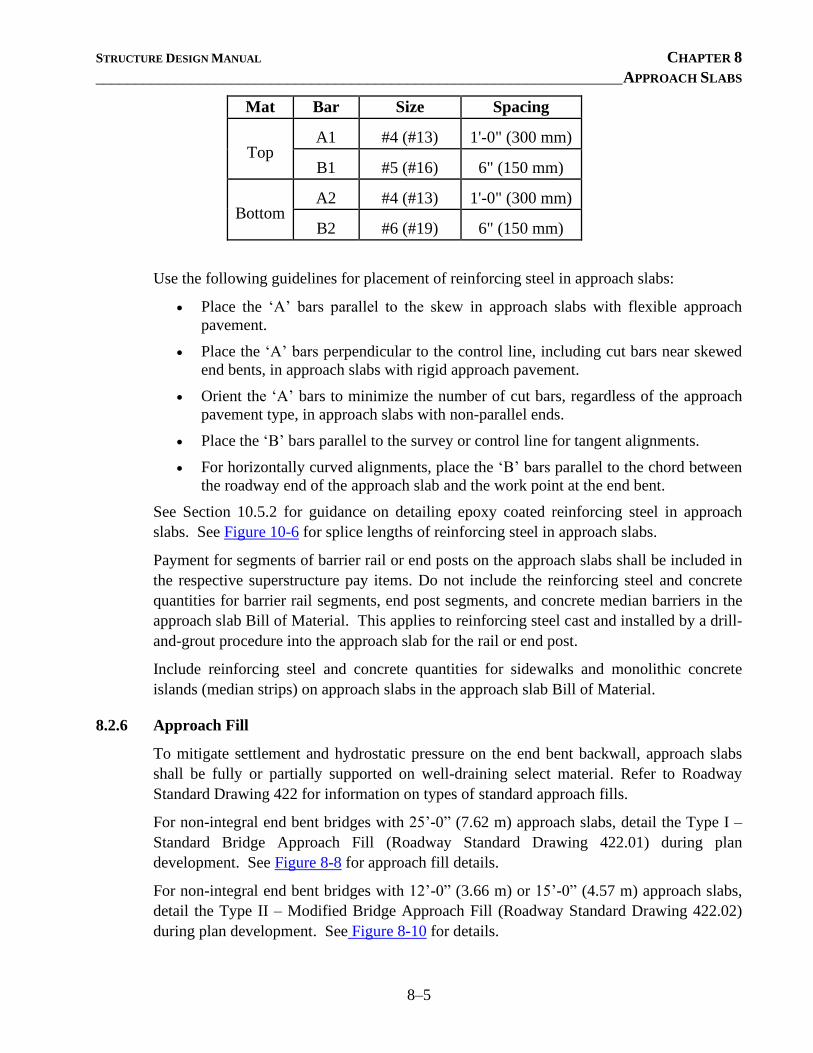
STRUCTURE DESIGN MANUAL CHAPTER 8
__________________________________________________________________ APPROACH SLABS
8–5
Mat Bar Size Spacing
Top A1 #4 (#13) 1'-0" (300 mm)
B1 #5 (#16) 6" (150 mm)
Bottom A2 #4 (#13) 1'-0" (300 mm)
B2 #6 (#19) 6" (150 mm)
Use the following guidelines for placement of reinforcing steel in approach slabs:
• Place the ‘A’ bars parallel to the skew in approach slabs with flexible approach
pavement.
• Place the ‘A’ bars perpendicular to the control line, including cut bars near skewed
end bents, in approach slabs with rigid approach pavement.
• Orient the ‘A’ bars to minimize the number of cut bars, regardless of the approach
pavement type, in approach slabs with non-parallel ends.
• Place the ‘B’ bars parallel to the survey or control line for tangent alignments.
• For horizontally curved alignments, place the ‘B’ bars parallel to the chord between
the roadway end of the approach slab and the work point at the end bent.
See Section 10.5.2 for guidance on detailing epoxy coated reinforcing steel in approach
slabs. See Figure 10-6 for splice lengths of reinforcing steel in approach slabs.
Payment for segments of barrier rail or end posts on the approach slabs shall be included in
the respective superstructure pay items. Do not include the reinforcing steel and concrete
quantities for barrier rail segments, end post segments, and concrete median barriers in the
approach slab Bill of Material. This applies to reinforcing steel cast and installed by a drill-
and-grout procedure into the approach slab for the rail or end post.
Include reinforcing steel and concrete quantities for sidewalks and monolithic concrete
islands (median strips) on approach slabs in the approach slab Bill of Material.
8.2.6 Approach Fill
To mitigate settlement and hydrostatic pressure on the end bent backwall, approach slabs
shall be fully or partially supported on well-draining select material. Refer to Roadway
Standard Drawing 422 for information on types of standard approach fills.
For non-integral end bent bridges with 25’-0” (7.62 m) approach slabs, detail the Type I –
Standard Bridge Approach Fill (Roadway Standard Drawing 422.01) during plan
development. See Figure 8-8 for approach fill details.
For non-integral end bent bridges with 12’-0” (3.66 m) or 15’-0” (4.57 m) approach slabs,
detail the Type II – Modified Bridge Approach Fill (Roadway Standard Drawing 422.02)
during plan development. See Figure 8-10 for details.
STRUCTURE DESIGN MANUAL CHAPTER 8
__________________________________________________________________ APPROACH SLABS
8–6
For integral end bent bridges, regardless of the approach slab length, use Standard drawing
BAS5, to detail the Type I bridge approach fill as well as the Type A – Alternate Bridge
Approach Fills (Roadway Standard Drawings 422.01 and 422.03, respectively) during plan
development. See Figure 8-9 for details and place the following note on the plans:
At the Contractor’s option, “Type A – Alternate Approach Fill” in lieu of “Type
I – Standard Approach Fill” may be constructed at no additional cost to the
Department.
For non-integral bridges with MSE walls constructed in front of end bent caps, detail the
Type III – Reinforced Bridge Approach Fill (corresponds with Roadway Detail Drawing
422D10) during plan development. See Figure 8-12 for details.
Approach fills for integral bridges with mechanically stabilized earth (MSE) walls
constructed in front of the end bent cap, shall be addressed on a case-by-case basis.
Do not include a pay item for the approach fills. Approach fills are Roadway pay items.
8.2.7 Guardrail Attachment
For bridges with a segment of the barrier rail or end post on the approach slab, as described
in Section 8.2.3, detail the guardrail anchor unit (GRAU) attached to the barrier rail
segment or end post on the approach slab.
Refer to Section 6.2.4.4 for guidance on guardrail attachments. Do not detail a guardrail
anchor assembly in locations not specified on the Structure Recommendations or the
Roadway plans.
8.3 APPROACH SLAB FINISH
The riding surface of approach slabs that do not have an asphalt overlay shall be grooved in
accordance with Section 6.2.2.10. Do not reduce the length of grooving by any additional
clearance from the end of approach slabs adjacent to rigid approach pavement. Reduce the
length of grooving by the 6 inch (150 mm) bevel, but not by any additional clearance from
the end of the bevel, for approach slabs adjacent to flexible approach pavement. Add the
grooving area for the approach slabs to that of the bridge deck on the Superstructure Bill of
Material. Include the total quantity in square feet for the “Grooving Bridge Floors” pay
item in the Total Bill of Material.
See Section 6.2.2.10 for bridge lengths that require rideability tests on riding surfaces of
bridge floors. For these bridges, require rideability tests on riding surfaces of approach
slabs as well.

STRUCTURE DESIGN MANUAL CHAPTER 8
__________________________________________________________________ APPROACH SLABS
8–7
8.4 CONSTRUCTION ELEVATIONS
See Section 6.2.2.9 for information regarding construction elevations required for approach
slabs.
STRUCTURE DESIGN MANUAL CHAPTER 9 __________________________________________________ REINFORCED CONCRETE CULVERTS
9–i
CONTENTS
Chapter 9 ..................................................................................................................................... 9–1
9.1 General ........................................................................................................................ 9–1
9.2 Design and Rating ........................................................................................................ 9–1
9.2.1 Culvert Length ................................................................................................ 9–1
9.2.2 Design Fill Depth ............................................................................................ 9–1
9.2.3 Culvert Design ................................................................................................ 9–2
9.2.4 Culvert Load Rating ........................................................................................ 9–3
9.3 Culvert Types ............................................................................................................... 9–3
9.3.1 Cast-In-Place Box Culverts ............................................................................. 9–3
9.3.2 Optional Precast Box Culverts ......................................................................... 9–4
9.3.3 Required Precast Box Culverts ........................................................................ 9–4
9.3.4 Three-Sided Bottomless Culverts .................................................................... 9–5
9.4 Culvert Detailing .......................................................................................................... 9–6
9.4.1 Location Sketch............................................................................................... 9–6
9.4.2 Hydraulic Data ................................................................................................ 9–7
9.4.3 Profile along Centerline Culvert ...................................................................... 9–7
9.4.4 Total Structure Quantities ................................................................................ 9–7
9.4.4.1 Culvert Excavation ........................................................................... 9–8
9.4.4.2 Foundation Conditioning Material .................................................... 9–9
9.4.5 Culvert Section ................................................................................................ 9–9
9.4.6 End Elevation .................................................................................................. 9–9
9.4.7 Part Plans of Roof and Floor Slabs .................................................................9–10
9.4.8 Section of Barrel ............................................................................................9–10
9.4.8.1 Staged Construction .........................................................................9–11
9.4.9 Culvert Wings ................................................................................................9–11
9.5 Guardrail Anchor Assemblies ......................................................................................9–12
9.6 Culvert Extensions ......................................................................................................9–13
9.7 Miscellaneous Details..................................................................................................9–13
9.7.1 Catch Basins ..................................................................................................9–13
9.7.2 Rip Rap ..........................................................................................................9–13
9.7.3 Arch Culverts .................................................................................................9–13
9.8 Special Notes ..............................................................................................................9–14
9.8.1 Live Load .......................................................................................................9–14
9.8.2 Metric Projects ...............................................................................................9–14
9.8.3 Culvert Diversion ...........................................................................................9–14
9.8.4 Federal Aid ....................................................................................................9–14
9.8.5 FEMA Regulations .........................................................................................9–14
9.8.6 Major Culverts ...............................................................................................9–15
9.8.7 Bridge Replacements ......................................................................................9–15
9.8.8 Intersecting Pipes ...........................................................................................9–15
9.8.9 Required Falsework........................................................................................9–15

STRUCTURE DESIGN MANUAL CHAPTER 9 __________________________________________________ REINFORCED CONCRETE CULVERTS
9–ii
9.8.10 Required Camber ...........................................................................................9–16
STRUCTURE DESIGN MANUAL CHAPTER 9 __________________________________________________ REINFORCED CONCRETE CULVERTS
9–1
CHAPTER 9
REINFORCED CONCRETE CULVERTS
9.1 GENERAL
The most common function of a culvert is to allow water to flow underneath a roadway.
Culverts may also serve as underpasses for pedestrians, wildlife and low volume roadways.
Culverts are designed to support external loadings such as vehicular load, water pressure,
earth pressure and surcharge. Culverts are load rated for transient load (typically vehicular
load) or permanent load (typically self-weight and earth load) depending on the fill depth.
9.2 DESIGN AND RATING
9.2.1 Culvert Length
Use the Culvert Survey and Hydraulic Design Report and the Roadway plans to compute
the culvert length.
The required culvert length is computed from the roadway survey line to each end of the
culvert, measured along the centerline of culvert. The normal distance from the roadway
survey line to each culvert end is comprised of three components:
• The distance from the roadway survey line to the edge of the roadway shoulder.
• The distance from the edge of the shoulder to the point where the fill slope
intersects an elevation 9 inches (230 mm) above the top of the culvert top slab.
• A distance of 1'-3" (380 mm) representing the culvert headwall thickness.
Skew the sum of these three distances as necessary and round up to the nearest preferred
increment of measurement. Show the overall culvert length on the plans as the sum of the
lengths from the left and right of the roadway survey line.
9.2.2 Design Fill Depth
Use the Culvert Survey and Hydraulic Design Report and the Roadway plans to compute
the culvert design fill depth. For cast-in-place and precast culverts, compute the maximum
and minimum design fill depths as follows:
• Define the following survey line offsets: survey line (no offset), shoulder points,
and any additional preferred offsets in-between (such as crown break locations
and/or grade points offset from survey line). For each defined survey line offset,
determine the grade point elevation change. Establish check points at intersection
locations between outside edges of the culvert and the defined survey line offsets.
Determine surface elevations at each check point using horizontal alignment data,
STRUCTURE DESIGN MANUAL CHAPTER 9 __________________________________________________ REINFORCED CONCRETE CULVERTS
9–2
vertical profile data, and the grade point elevation changes. The alignment and
profile data are provided in the Roadway plans.
• Determine the bed elevation at each check point by using the bed elevation at the
roadway survey line and the bed slope, both of which are provided in the Culvert
Survey and Hydraulic Design Report.
• Add the vertical clearance (i.e. barrel opening height) to the bed elevation at each
check point to produce the bottom of top slab elevation for each check point.
• Subtract the bottom of top slab elevation from the matching surface elevation for
each check point. Report the maximum elevation difference as the maximum
design fill depth and the minimum elevation difference as the minimum design fill
depth.
For precast culverts, report the design earth cover as the elevation difference between the
point of maximum fill and the bottom of the top slab.
See Figure 9-1 for example computations of culvert length and design fill depth.
See Section 9.8.10 to determine when to camber the culvert.
9.2.3 Culvert Design
Design cast-in-place reinforced concrete culverts using the Load and Resistance Factor
Design (LRFD) method in accordance with the AASHTO LRFD Bridge Design
Specifications. Analyze the culvert section with the maximum and minimum fill depths
separately to ensure that the specified slab and wall thicknesses and the slab and wall steel
reinforcement satisfy the AASHTO limit state requirements for flexure, shear, and crack
control. Culverts are commonly analyzed as two-dimensional plane frames.
Use minimum slab and wall thicknesses of 8 inches (205 mm). For ease of construction,
specify matching spacing of reinforcement in the exterior faces of the top slab, bottom slab,
and exterior walls, including corner bars.
Do not design a precast culvert required for a project or optional to a cast-in-place culvert.
Precast culverts will be designed by suppliers.
For precast and cast-in-place three-sided bottomless culverts, design footings in accordance
with the AASHTO LRFD Bridge Design Specifications.
According to the AASHTO LRFD Bridge Design Specifications, the effects of live load on
culvert design may be neglected for the following conditions:
• For single-span culverts, where the depth of fill is more than 8 feet and exceeds the
span length (i.e. barrel opening width);
• For multiple-span culverts, where the depth of fill exceeds the distance between
inside faces of end walls (i.e. sum of barrel opening widths and interior wall
thicknesses).

STRUCTURE DESIGN MANUAL CHAPTER 9 __________________________________________________ REINFORCED CONCRETE CULVERTS
9–3
For LRFD culvert designs in which live load and live load surcharge may be neglected,
consider accounting for permanent loads only. However, although defined in AASHTO as a
transient load and not as a permanent load, water load (i.e. stream pressure) should be
included in the design unless the load reduces the overall load effect under consideration.
9.2.4 Culvert Load Rating
Rate cast-in-place and precast culverts using the Load and Resistance Factor Rating
(LRFR) provisions of the AASHTO Manual for Bridge Evaluation. Ensure that the culvert
section is satisfactory with respect to flexure and shear capacity for the AASHTO HL-93
design truck and for the North Carolina Legal Load Trucks. Rating factors shall be greater
than or equal to 1.
According to the AASHTO Manual for Bridge Evaluation, the effects of live load and live
load surcharge on culvert load rating may be neglected for the conditions described in
Section 9.2.3. For LRFR culvert load ratings under those fill conditions, account for
permanent loads only. Compute moment and shear rating factors by dividing the factored
moment or shear resistance by the factored moment or shear due to permanent loads (and
water load depending on overall load effect).
Place computed LRFR rating factors in the summary table on Standard Drawing LRFR5 for
non-interstate traffic, LRFR6 for interstate traffic, or LRFR7 for culverts with deep fills,
whichever is appropriate. Include the completed LRFR Standard in the culvert plans after
the plan sheet showing the culvert profile and location sketch.
9.3 CULVERT TYPES
9.3.1 Cast-In-Place Box Culverts
Detail cast-in-place reinforced concrete box culverts in accordance with the Culvert
Standard Drawings. Use the Culvert Barrel Standards, Culvert Wing Standards, and LRFR
Standards in conjunction with the available barrel section cell details to prepare the plans
for cast-in-place box culverts. Barrel and Wing Standards are available in 15 increments
for headwalls skewed between 45 and 135.
For a cast-in-place box culvert with a sloped and/or tapered inlet, see the example details
provided in Figure 9-2 and Figure 9-3.
For a cast-in-place single barrel box culvert, see the example details provided in Figure 9-4,
Figure 9-5, and Figure 9-6.
Cast-in-place box culverts shall be paid for per cubic yard (cubic meter) of “Class A
Concrete” and per lbs (kg) of “Reinforcing Steel”.
See Section 9.4 for detailing guidelines for cast-in-place box culverts.
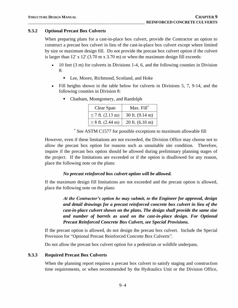
STRUCTURE DESIGN MANUAL CHAPTER 9 __________________________________________________ REINFORCED CONCRETE CULVERTS
9–4
9.3.2 Optional Precast Box Culverts
When preparing plans for a cast-in-place box culvert, provide the Contractor an option to
construct a precast box culvert in lieu of the cast-in-place box culvert except where limited
by size or maximum design fill. Do not provide the precast box culvert option if the culvert
is larger than 12' x 12' (3.70 m x 3.70 m) or when the maximum design fill exceeds:
• 10 feet (3 m) for culverts in Divisions 1-4, 6, and the following counties in Division
8:
▪ Lee, Moore, Richmond, Scotland, and Hoke
• Fill heights shown in the table below for culverts in Divisions 5, 7, 9-14, and the
following counties in Division 8:
▪ Chatham, Montgomery, and Randolph
Clear Span Max. Fill*
≤ 7 ft. (2.13 m) 30 ft. (9.14 m)
≥ 8 ft. (2.44 m) 20 ft. (6.10 m)
* See ASTM C1577 for possible exceptions to maximum allowable fill
However, even if these limitations are not exceeded, the Division Office may choose not to
allow the precast box option for reasons such as unsuitable site condition. Therefore,
inquire if the precast box option should be allowed during preliminary planning stages of
the project. If the limitations are exceeded or if the option is disallowed for any reason,
place the following note on the plans:
No precast reinforced box culvert option will be allowed.
If the maximum design fill limitations are not exceeded and the precast option is allowed,
place the following note on the plans:
At the Contractor’s option he may submit, to the Engineer for approval, design
and detail drawings for a precast reinforced concrete box culvert in lieu of the
cast-in-place culvert shown on the plans. The design shall provide the same size
and number of barrels as used on the cast-in-place design. For Optional
Precast Reinforced Concrete Box Culvert, see Special Provisions.
If the precast option is allowed, do not design the precast box culvert. Include the Special
Provision for “Optional Precast Reinforced Concrete Box Culverts”.
Do not allow the precast box culvert option for a pedestrian or wildlife underpass.
9.3.3 Required Precast Box Culverts
When the planning report requires a precast box culvert to satisfy staging and construction
time requirements, or when recommended by the Hydraulics Unit or the Division Office,
STRUCTURE DESIGN MANUAL CHAPTER 9 __________________________________________________ REINFORCED CONCRETE CULVERTS
9–5
develop plans for a precast box culvert using the supplied information and Culvert Standard
PBC1.
The Contractor will be responsible for the design of the precast box culvert. Detail only the
opening size and culvert length, number of boxes, cast-in-place headwall, cast-in-place
wings, and guardrail attachment, if required. Do not detail the slab thickness, wall
thickness, or barrel reinforcement other than the ‘D’ bars that dowel into the cast-in-place
headwall and curtain wall. When determining the length of the culvert, assume both the
wall and slab thicknesses to be one-twelfth of the horizontal clear span of one barrel, but do
not detail it as such.
Complete or include the following items on Culvert Standard PBC1:
• Typical Section - Show the width and height of the box.
• Elevation - Show the length of the culvert, along with the locations of weep holes.
• Standard Notes - Enter the design earth cover.
• Plan View - Delete the view that is not applicable to the project.
• Bill of Material and Bar Schedule
• Skewed Precast Box Culverts - Select the appropriate detail from Figure 9-7.
Detail a 1½" (38 mm) space between each precast box for multiple barrel culverts as shown
in Figure 9-8.
For example details, see Figure 9-8, Figure 9-9, and Figure 9-10.
Precast box culverts shall be paid for on a lump sum basis. Include the Special Provision
for “Precast Reinforced Concrete Box Culvert”.
Do not detail a precast box culvert for use as a pedestrian or wildlife underpass.
See Section 9.4 for additional detailing guidelines for precast box culverts.
9.3.4 Three-Sided Bottomless Culverts
Detail either a precast or cast-in-place three-sided bottomless culvert when noted on the
Culvert Survey and Hydraulic Design Report.
Three-sided bottomless culverts may be advantageous when a high rock line exists (within
3 feet to 5 feet of the ground surface). Variable-depth footings should be cast-in-place
below the streambed and must be keyed into rock.
For precast three-sided bottomless culverts, the Contractor will be responsible for the
design of the barrel section, wing walls, headwalls and cast-in-place footings. Detail both
the arch and flat-top shaped sections in the plans unless otherwise indicated. Detail the
opening size, culvert length, and number of cells. To determine the culvert length, assume
the slab thickness to be one-twelfth of the horizontal clear span, but do not detail it as such.
Include foundation design parameters and notes provided by the Geotechnical Engineering
Unit in the plans.
STRUCTURE DESIGN MANUAL CHAPTER 9 __________________________________________________ REINFORCED CONCRETE CULVERTS
9–6
Precast three-sided bottomless culverts shall be paid for on a lump sum basis. Include the
Special Provision for “Precast Reinforced Concrete Three Sided Culvert”.
Cast-in-place three-sided bottomless culverts shall be paid for per cubic yard (cubic meter)
of “Class A Concrete” and per lbs (kg) of “Reinforcing Steel”.
See Section 9.4 for detailing guidelines for three-sided bottomless culverts.
9.4 CULVERT DETAILING
The following sections provide information regarding details required for all cast-in-place
and precast box culverts unless noted otherwise.
9.4.1 Location Sketch
Orient the location sketch on the plan sheet so that the roadway survey line is vertical with
stations increasing from bottom to top. Include the following items on the location sketch
for cast-in-place and precast box culverts:
• Roadway survey line designation (-L-, -Y-, etc.)
• Project station along the survey line at the centerline of the culvert
• North arrow
• Existing structures, roads, buildings, and drainage pipes shown with a dashed line;
also show existing wood lines, stream outlines, and other terrain features.
• Proposed culvert outline shown as a solid line
• Skew angle between roadway survey line and culvert centerline
• Name of the stream
• Flow direction of the stream
• Destination arrows on the roadway
• Roadway grade point elevation at the project station, culvert bed elevation beneath
the project station, and roadway fill slopes; place this information in a corner of or
beneath the location sketch in the following manner:
Grade Point Elev. @ Station ______ = ____________
Bed Elev. @ Station ______ = ____________
Roadway Slopes ______:1
• Bench mark description and its elevation in or adjacent to the location sketch
• Top of footing elevations for culverts without floor slabs
STRUCTURE DESIGN MANUAL CHAPTER 9 __________________________________________________ REINFORCED CONCRETE CULVERTS
9–7
9.4.2 Hydraulic Data
Show the following information, attained from the Culvert Survey and Hydraulic Design
Report, near the location sketch for all culvert types:
• Design Discharge
• Frequency of Design Flood
• Design High Water Elevation
• Drainage Area
• Base Discharge (Q100)
• Base High Water Elevation
In addition to the above data, show the Overtopping Flood Data for all Federal Aid projects
when the data is provided.
• Overtopping Discharge
• Frequency of Overtopping Flood
• Overtopping Flood Elevation
Place the applicable note provided on the Culvert Survey and Hydraulic Design Report
when Overtopping Flood Data is not required.
The high water elevation shown in the Culvert Survey and Hydraulic Design Report applies
to the inlet end of the culvert and is based on an estimated culvert length. Therefore, adjust
the high water elevation appropriately based on the actual location of the inlet end shown
on the plans. Show this adjusted elevation to the nearest tenth of a foot (hundredth of a
meter). Adjust the elevation as a direct variation of the grade of stream bed. Thus, if the
upstream end of a box culvert on a 1.2% grade is 8'-4" (2.54 m) longer than the Culvert
Survey and Hydraulic Design Report shows, the high water elevation should be raised 0.1
feet (30 mm). If the difference between the high water elevation shown in the Culvert
Survey and Hydraulic Design Report and the adjusted high water elevation is greater than
or equal to 0.1 feet (30 mm), contact the Hydraulics Unit for their review and approval.
9.4.3 Profile along Centerline Culvert
Show the natural ground profile along the centerline of the culvert, including approximate
elevations at break points and approximate distances between for cast-in-place and precast
box culverts. The Hydraulics Unit should include the profile in the Culvert Survey and
Hydraulic Design Report. If more details are required, contact the Hydraulics Unit.
9.4.4 Total Structure Quantities
Compute and tabulate the quantities of Class A concrete in cubic yards (cubic meters) and
reinforcing steel in lbs (kg) for cast-in-place culverts. For stage-constructed culverts, show
the individual quantities for each stage.
STRUCTURE DESIGN MANUAL CHAPTER 9 __________________________________________________ REINFORCED CONCRETE CULVERTS
9–8
Also include applicable quantities for culvert excavation and foundation conditioning
material as prescribed in the following sections.
9.4.4.1 Culvert Excavation
For cast-in-place or precast box culverts, compute culvert excavation in accordance
with Figure 9-11. List “Culvert Excavation, Station ______” on the plans in the Total
Structure Quantities on a lump sum basis. Include the quantity per cubic yard (cubic
meter) in the estimates and proposals.
For cast-in-place or precast box culverts that require the removal of unsuitable
material, include the undercut excavation within the limits of the culvert excavation.
To calculate the culvert excavation for precast box culverts, assume the wall and slab
thicknesses are equal to 10% of the horizontal clear span of one barrel.
For precast and cast-in-place three-sided bottomless culverts, compute the excavation
quantity for the footings into rock based on 6 inches (150 mm) minimum embedment
depth. Provide this quantity for “Foundation Excavation” instead of “Culvert
Excavation” in the Total Structure Quantities per cubic yard (cubic meter). Also
compute the excavation quantity of remaining material above rock, if any, required
for the construction of the footing. List “Unclassified Structure Excavation” in the
Total Structure Quantities on a lump sum basis. Include the quantity per cubic yard
(cubic meter) in the estimates and proposals.
Unsuitable Material
When the bottom of a cast-in-place or precast box culvert is above the limits of
unsuitable material, show the following note on the culvert plans:
No work shall be done on the culvert at Sta. _________ until the area of the
box culvert has been undercut to Elev. ____ and unsuitable material
replaced with suitable material, properly compacted to the elevation of the
bottom of the proposed floor slab. The limits of this undercut excavation
shall be at least the limits of the box culvert including the wings. No
separate payment will be made for any temporary sheeting, undercut, or
unsuitable material replacement as required to construct the proposed
culvert. Payment is included in the lump sum price for Culvert Excavation.
Low Flow Channels
When the Culvert Survey and Hydraulic Design Report calls for a low flow channel,
show a plan view of the culvert specifying the sill locations and label the bed
material. Provide an elevation view detailing the height(s) of the sills. Place the
notes listed on the Culvert Survey and Hydraulic Design Report and the following
note on the plans:
STRUCTURE DESIGN MANUAL CHAPTER 9 __________________________________________________ REINFORCED CONCRETE CULVERTS
9–9
The entire cost of work required to place excavated or supplemental
material as shown on the plans shall be included in the lump sum price for
Culvert Excavation.
See Figure 9-12 for typical culvert sill details.
9.4.4.2 Foundation Conditioning Material
For foundations of cast-in-place and precast box culverts, use a 12 inch (300 mm)
thick pad of Foundation Conditioning Material over an area with length equal to that
of the bottom slab and width equal to the total culvert width plus 4'-0" (1.22 m). Do
not compute a quantity for standard turned back wings. Use a unit weight of 1.904
tons/yd3 (2.26 metric tons/m3) for this material to compute the quantity rounded to the
nearest ton (metric ton). Provide this quantity for “Foundation Conditioning
Material, Box Culvert” in the Total Structure Quantities.
When calculating a quantity of Foundation Conditioning Material for precast box
culverts, assume a wall thickness equal to 10% of the horizontal clear span of one
barrel.
9.4.5 Culvert Section
Include a detail representing the section along the centerline of the culvert taken normal to
the centerline of survey. Provide the appropriate missing information in this section on the
Standard Drawings for cast-in-place and precast box culverts; eliminate references to
reinforcement in this detail for precast box culverts. In addition, show the dimension from
the bed elevation to the weep hole. Compute this dimension by determining the difference
between the normal flow line and the centerline bed elevation, as shown on the Culvert
Survey and Hydraulic Design Report, adding 6 inches (150 mm) to the elevation difference,
and then rounding to the next ½ inch (10 mm).
Detail transverse construction joints (oriented normal to the culvert centerline) in culverts
exceeding 70 feet (21.0 m) in length. Do not cut or space the reinforcing steel to account
for the joints. Where transverse construction joints are required, show a typical joint on the
plans with a reference to the following note:
Transverse construction joints shall be used in the barrel, spaced to limit the
pours to a maximum of 70 feet (21.0 m). Location of joints shall be subject to
approval of the Engineer.
9.4.6 End Elevation
Include a detail representing the section at the end of the culvert, parallel to the headwall
and along the skew, if any. If each end of the culvert contains a different headwall angle,
provide a separate detail for each end. Provide the appropriate missing information in this
section on the Standard Drawings for cast-in-place and precast box culverts. For multiple
barrel precast box culverts, modify this detail to show a 1½" (38 mm) space between each
STRUCTURE DESIGN MANUAL CHAPTER 9 __________________________________________________ REINFORCED CONCRETE CULVERTS
9–10
precast box, skewed if necessary. For cast-in-place and precast box culverts with headwall
angles other than those provided on the Standard Drawings, modify this end view
accordingly.
9.4.7 Part Plans of Roof and Floor Slabs
Include a detail representing partial plan views of the top and bottom slabs. Ensure the
detail contains information such as barrel reinforcement, culvert length, project
identification station and skew angle, headwall angles (if different from skew angle at
project identification station), and the distance between the inside faces of the exterior
walls. Provide the appropriate missing information in this partial-plan detail on the
Standard Drawings for cast-in-place and precast box culverts; eliminate references to
reinforcement in this detail for precast box culverts.
9.4.8 Section of Barrel
Include a detail representing the typical barrel section normal to the centerline of the
culvert. Section cell details of various barrel sizes and number of barrels are available for
cast-in-place culverts. For single barrel cast-in-place culverts with a vertical clearance of
8 feet (2.54 m) or less, detail continuous high chair uppers (CHCU) in the top slab to
support the corner ‘A’ bars. When the clear distance between the bottom mat of transverse
steel and the top mat of longitudinal steel in the top or bottom slab exceeds 15 inches (380
mm), use a Standee bar. Detail the Standee bar in accordance with the CRSI “Manual of
Standard Practice”.
Detail the actual number of ‘C’ bars in the barrel section. Place the following note near the
barrel section detail:
There are _____ ‘C’ bars in section of barrel.
For all multiple barrel cast-in-place culverts, detail a permitted construction joint in the
bottom slab located 12 inches (300 mm) from an interior wall and place the following note
on the plans:
Steel in the bottom slab may be spliced at the permitted construction joint at the
Contractor’s option. Extra weight of steel due to the splices will be paid for by
the Contractor.
For cast-in-place culverts with a vertical clearance of 4 feet (1.2 m) or less, do not detail a
construction joint at the bottom of the haunches located at the top of exterior and interior
walls. Provide “No Construction Joint Permitted” notation in the section detail with an
arrow directed to the bottom of the haunches.
For cast-in-place culverts with a vertical clearance greater than 4 feet (1.2 m) but 8 feet
(2.4 m) or less, detail an optional construction joint at the bottom of the haunches located at
the top of exterior and interior walls. Provide “Permitted Construction Joint” notation in
the section detail with an arrow directed to the bottom of the haunches.
STRUCTURE DESIGN MANUAL CHAPTER 9 __________________________________________________ REINFORCED CONCRETE CULVERTS
9–11
For cast-in-place culverts with a vertical clearance of 9 feet (2.7 m) or greater, detail a
required construction joint at the bottom of the haunches located at the top of exterior and
interior walls. Provide “Construction Joint” notation in the section detail with an arrow
directed to the bottom of the haunches.
9.4.8.1 Staged Construction
For cast-in-place culverts constructed in stages, detail a construction joint in the
bottom slab consistent with the staging plans proposed by the Roadside
Environmental and Hydraulics Units.
Detail the size and spacing of the ‘B’ bars in each interior wall face as required by
design. Detail corner ‘A’ bars in each interior wall face, spliced to the interior wall
‘B’ bars, at the bottom of interior walls. Match the size and spacing of the corner ‘A’
bars with that of the ‘B’ bars in each interior wall face. Provide vertical leg lengths of
the corner ‘A’ bars that are at least the tension lap splice length for the bar size.
Support the horizontal legs of the ‘A’ bars in the same plane as the bottom mat of
reinforcing steel in the bottom slab. Detail the size and spacing of the corner ‘A’ bars
in the exterior walls as required by design.
Do not detail the top slab with longitudinal joints. Do not detail additional corner ‘A’
bars at the top of interior walls.
Edge beams are not required to connect adjacent segments of culverts constructed in
stages along the culvert length.
9.4.9 Culvert Wings
Detail cast-in-place turned back wings and footings in accordance with the Culvert Wing
Standards for cast-in-place and precast box culverts and for cast-in-place three-sided
bottomless culverts. Precast wing walls and footings will not be allowed. The Culvert
Wing Standards are available for 2:1 fill slope conditions and are tailored for cast-in-place
box culverts.
For acute corners of multiple barrel culverts with skews less than or equal to 45 or greater
than or equal to 135 and with vertical clearance of 8 feet (2.44 m) or more, provide
counterfort details included in the Culvert Wing Standards to strengthen the barrel corners.
Provide a 1 inch (25 mm) expansion joint in the wings of all cast-in-place and precast
culverts. The Culvert Wing Standards incorporate this expansion joint in the wings for
cast-in-place culverts. For precast culverts, modify the appropriate Culvert Wing Standard
to provide 1 inch (25 mm) expansion joint material at the junction of the wing and the
precast end unit rather than in the wing. To prevent the migration of fine material through
the joint, place the following note on the plans for cast-in-place and precast culverts with
turned back wings:
STRUCTURE DESIGN MANUAL CHAPTER 9 __________________________________________________ REINFORCED CONCRETE CULVERTS
9–12
A 3 foot (900 mm) strip of filter fabric shall be attached to the fill face of the
wing covering the entire length of the expansion joint.
For wings on skewed precast box culverts, place the following note on the modified
Culvert Wing Standard and place an asterisk on the dimensions locating the intersection of
the wing and curtain wall footings and the start of the wing slope:
If the option of 90 skewed ends of the precast box is used, dimensions marked
with an asterisk will need adjustment.
For multiple barrel precast culverts, place the following note on the plans:
One permitted construction joint will be allowed in the end curtain wall.
For unusual skew conditions or for fill slopes other than 2:1, use Figure 9-13, Figure 9-14,
and Figure 9-15 to determine the geometry for wing layout details.
For an example of turned back wings for a cast-in-place box culvert, see Figure 9-6.
For an example of turned back wings for a precast box culvert, see Figure 9-10.
For precast three-sided bottomless culverts, precast wing walls will be allowed. Precast
footings will not be allowed. The Contractor will be responsible for the design of the
precast and cast-in-place members.
9.5 GUARDRAIL ANCHOR ASSEMBLIES
For cast-in-place or precast culverts, if the skewed culvert width (including the walls) is
less than or equal to 22'-6" (6.86 m) and regardless of the fill depth above the top slab, use
an alternative guardrail design with a guardrail post spacing of up to 25'-0" (7.62 m)
eliminating the need for anchorage into the culvert. See Roadway Detail Drawing 862D01.
However, if the skewed culvert width is greater than 22'-6" (6.86 m) and the fill depth
above the top slab at the location of the guardrail posts is less than or equal to 3'-5"
(1.04 m), include details in the plans for anchoring guardrail to the culvert due to
inadequate post clearance and embedment depth required per Roadway Detail Drawing
862D01. Detail the guardrail anchor assemblies spaced at 6'-3" (1.905 m) centers. See
Standard GRA1 and Figure 9-16 for guardrail anchorage details for cast-in-place culverts.
See Figure 9-17 for guardrail anchorage details for precast culverts. See Roadway Standard
Drawing 862.03 Sheet 7 of 7 for guardrail, post, and post base plate details when anchorage
into box culverts is required.
Coordinate with the Roadway Design Unit to ensure the Roadway plans are properly
detailed. Furnish the Roadway Design Unit with the guardrail anchor assembly spacing
used on each culvert.
STRUCTURE DESIGN MANUAL CHAPTER 9 __________________________________________________ REINFORCED CONCRETE CULVERTS
9–13
9.6 CULVERT EXTENSIONS
When an existing culvert is to be extended, design the extension portion using the AASHTO
LRFD Bridge Design Specifications and rate the extension portion using the LRFR
provisions of the AASHTO Manual for Bridge Evaluation.
For culvert extensions, use a minimum slab and exterior wall thickness of 8 inches
(205 mm). For multiple barrel culvert extensions, detail interior wall thickness to match the
existing interior wall thickness.
Detail #6 (#19) dowels at 1'-6" (450 mm) centers for the top and bottom slabs and exterior
walls. See Figure 9-18 for edge beam connection details. Place the following notes on the
plans:
Dowels shall be used to connect the culvert extension to the existing culvert as
shown. For note regarding setting of dowels, see Sheet SN (Sheet SNSM).
If approved by the Engineer, the Contractor may use the existing wings as
temporary shoring for the construction of the culvert extensions. In this case,
the bottom slab of the extension shall be poured at least 72 hours prior to
cutting the wings. The wings may be cut earlier provided the slab concrete
strength has reached a minimum compressive strength of 1500 psi (10.3 MPa).
9.7 MISCELLANEOUS DETAILS
9.7.1 Catch Basins
Where an opening is required in the top slab for a catch basin, provide for 4 inch (100 mm)
corner fillets and call for the steel in the opening to be cut and bent up if the catch basin is
reinforced. Provide extra bars to reinforce the opening if required.
9.7.2 Rip Rap
If scour is prevalent and if recommended by the Hydraulics Unit on the Culvert Survey and
Hydraulics Design Report, detail rip rap in front of the culvert wing, approximately 3 feet
(900 mm) above the wing footing. Also, when baffles are required, rip rap may be required
as a bed material to simulate a natural stream bottom.
9.7.3 Arch Culverts
Regardless of the culvert skew angle, the angle measured between the headwall and a line
perpendicular to the centerline of the arch culvert shall not exceed 20.
STRUCTURE DESIGN MANUAL CHAPTER 9 __________________________________________________ REINFORCED CONCRETE CULVERTS
9–14
9.8 SPECIAL NOTES
9.8.1 Live Load
For new culverts and culvert extensions designed using the Load and Resistance Factor
Design method, place the following note on the plans:
Assumed Live Load = HL 93
9.8.2 Metric Projects
For all metric projects, place the following notes on the plans:
All dimensions are in millimeters unless otherwise noted.
All elevations are in meters.
9.8.3 Culvert Diversion
For culvert diversion details and pay item, see Erosion Control Plans.
9.8.4 Federal Aid
For Federal Aid projects, provide the Federal Aid Project Number in the upper right hand
corner of the first culvert plan sheet. See Figure 9-4 for an example of the Federal Aid
Project Number placement. Also place the Sample Bar Replacement Chart, see Figure 10-
12, and the following note on the plans:
The Contractor shall provide independent assurance samples of reinforcing
steel as follows: For projects requiring up to 400 tons (360,000 kg) of
reinforcing steel, one 30 inch (760 mm) sample of each size bar used, and for
projects requiring over 400 tons (360,000 kg) of reinforcing steel, two 30 inch
(760 mm) samples of each size bar used. The sample bars should come from
steel actually used in the project and the sample bars should be replaced by
spliced bars as specified in the Sample Bar Replacement Chart. Payment for the
sample bars and replacement reinforcing steel shall be considered incidental to
various pay items.
9.8.5 FEMA Regulations
Refer to the Project Commitments sheets ("green sheets") in the Planning Document or the
Culvert Survey and Hydraulic Design Report to determine if the proposed culvert involves
a FEMA-regulated stream. For culvert projects involving FEMA-regulated streams, reserve
an area for a Professional Engineer’s seal on the sheets that include the following:
• the location sketch
• the profile along the centerline of the culvert
• the culvert section normal to the roadway
STRUCTURE DESIGN MANUAL CHAPTER 9 __________________________________________________ REINFORCED CONCRETE CULVERTS
9–15
• the end elevation of the culvert.
Place the following note above the area:
I hereby certify these plans are the as-built plans.
The as-built plans will be sealed by the Resident Engineer or the appropriate Division
personnel administering the contract.
See Figure 9-4 and Figure 9-5 for an example of the as-built seal area and note placement.
9.8.6 Major Culverts
Culverts with a total interior opening of 20 feet (6 m) or greater measured along the
centerline of the roadway are defined as major culverts. If applicable, place the following
note above the title block on the first culvert plan sheet:
Bridge No._____
9.8.7 Bridge Replacements
If a culvert is replacing an existing bridge, place the following note above the title block on
the first culvert plan sheet:
Replaces Bridge No. ______.
Also place the note on the plans pertaining to bridge replacements with subsequent removal
of the existing bridge from Section 5.2.7.
9.8.8 Intersecting Pipes
If possible, do not locate a pipe through a culvert exterior wall or wing wall. If intersecting
a pipe with a culvert is unavoidable, consider providing a junction box to either run the pipe
through the culvert top slab or run the pipe perpendicular into the culvert exterior wall.
If locating a pipe through a culvert exterior wall is necessary, detail the wall reinforcing
steel bent around the pipe and reinforce the area with additional bars. Place the following
note on the plans:
The _______ pipe through the sidewall of the culvert shall be located by the
Engineer. The reinforcing steel shall be field bent as necessary to clear pipe.
9.8.9 Required Falsework
For arch culverts or box culverts with a top slab thickness of 18 inches (455 mm) or greater,
place the following note on the plans:
Detailed drawings for falsework and forms for this __________ shall be
submitted. See Sheet SN (Sheet SNSM).

STRUCTURE DESIGN MANUAL CHAPTER 9 __________________________________________________ REINFORCED CONCRETE CULVERTS
9–16
9.8.10 Required Camber
Request subsurface investigations and required camber information from the Geotechnical
Engineering Unit for all box culverts with a design fill depth of 50 feet (15.25 m) or more
and for other box culverts deemed necessary by the Engineer. The camber value shall not
exceed one-half the elevation difference from the inlet of the culvert to the outlet.
When camber is required, place the following note on the plans:
The reinforced concrete box culvert shall be constructed with ____ inches (mm)
of camber to account for anticipated settlement.
STRUCTURE DESIGN MANUAL CHAPTER 10 __________________________________________________________________ REINFORCING STEEL
10–i
CONTENTS
Chapter 10 .................................................................................................................................. 10-1
10.1 General ....................................................................................................................... 10-1
10.2 Material Properties ...................................................................................................... 10-1
10.3 Bar Sizes ..................................................................................................................... 10-1
10.4 Detailing ..................................................................................................................... 10-2
10.4.1 General .......................................................................................................... 10-2
10.4.2 Bar Supports .................................................................................................. 10-2
10.4.3 Development Length and Splice Length ......................................................... 10-3
10.4.4 Bill of Material ............................................................................................... 10-5
10.4.5 Maximum Bar Lengths ................................................................................... 10-6
10.4.6 Independent Assurance Samples ..................................................................... 10-6
10.5 Corrosion Protection ................................................................................................... 10-6
10.5.1 Concrete Cover .............................................................................................. 10-6
10.5.2 Epoxy Coated Reinforcing Steel ..................................................................... 10-7
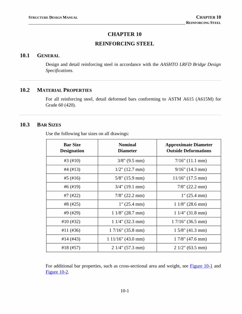
STRUCTURE DESIGN MANUAL CHAPTER 10 __________________________________________________________________ REINFORCING STEEL
10-1
CHAPTER 10
REINFORCING STEEL
10.1 GENERAL
Design and detail reinforcing steel in accordance with the AASHTO LRFD Bridge Design
Specifications.
10.2 MATERIAL PROPERTIES
For all reinforcing steel, detail deformed bars conforming to ASTM A615 (A615M) for
Grade 60 (420).
10.3 BAR SIZES
Use the following bar sizes on all drawings:
Bar Size
Designation
Nominal
Diameter
Approximate Diameter
Outside Deformations
#3 (#10) 3/8" (9.5 mm) 7/16" (11.1 mm)
#4 (#13) 1/2" (12.7 mm) 9/16" (14.3 mm)
#5 (#16) 5/8" (15.9 mm) 11/16" (17.5 mm)
#6 (#19) 3/4" (19.1 mm) 7/8" (22.2 mm)
#7 (#22) 7/8" (22.2 mm) 1" (25.4 mm)
#8 (#25) 1" (25.4 mm) 1 1/8" (28.6 mm)
#9 (#29) 1 1/8" (28.7 mm) 1 1/4" (31.8 mm)
#10 (#32) 1 1/4" (32.3 mm) 1 7/16" (36.5 mm)
#11 (#36) 1 7/16" (35.8 mm) 1 5/8" (41.3 mm)
#14 (#43) 1 11/16" (43.0 mm) 1 7/8" (47.6 mm)
#18 (#57) 2 1/4" (57.3 mm) 2 1/2" (63.5 mm)
For additional bar properties, such as cross-sectional area and weight, see Figure 10-1 and
Figure 10-2.
STRUCTURE DESIGN MANUAL CHAPTER 10 __________________________________________________________________ REINFORCING STEEL
10-2
10.4 DETAILING
10.4.1 General
Use the line symbology in Figure 1-4 when detailing reinforcing steel in contract plans.
When detailing reinforcing bars adjacent to concrete surfaces, show the clear dimension.
Show the center-to-center distance between parallel reinforcing bars, measured
perpendicular to the longitudinal axis of the bars.
For cast-in-place concrete, provide a clear distance between parallel bars of not less than
1.5 times the nominal bar diameter, 1.5 times the maximum coarse aggregate size, or 1½
inches (38 mm). For parallel bars detailed with a contact lap splice at the same or nearby
section, provide the required clear distance between the splice and adjacent splices or bars
as described above. In sections heavily reinforced with lap spliced bars, consider detailing
staggered splice locations or increasing the cross-section to reduce congestion of
reinforcement and ensure minimum clear distance can be achieved.
Consider detailing mechanical couplers when lap splices are not feasible. For example,
couplers are permitted to connect main flexural end bent and bent cap reinforcement when
the required lap splice length exceeds the provided clearance between existing and
proposed stage-constructed bridges.
For flexural reinforcement such as additional negative moment steel provided in the top
layer of bridge decks continuous over interior bents and near integral end bents, do not
terminate adjacent bars or more than half of the bars in a section at the same location.
Space the top longitudinal bars in end bent and bent caps to avoid interference with anchor
bolts or 4 inch diameter grout cans. Space the bottom longitudinal bars in end bent and
bent caps to avoid interference with embedded piles or vertical column reinforcement.
Provide reinforcement for shrinkage and temperature stresses near the exposed surfaces of
walls and slabs otherwise unreinforced. Space this reinforcement at a maximum of 18
inches (450 mm).
10.4.2 Bar Supports
Bar supports are commonly detailed to position reinforcing steel in concrete members such
as deck slabs, approach slabs, bent caps, culvert slabs, etc. Do not detail bar supports in
backwalls, barrier rails, parapets, sidewalks, footings, or culvert walls.
Detail standard bar supports whenever possible. Refer to the Concrete Reinforcing Steel
Institute (CRSI) Manual of Standard Practice and manufacturers' catalogs for commonly
available types and sizes of bar supports. The following bar support types and applications
are common in bridge and culvert members:
• Beam bolsters (B.B.), typically available in heights of 5 inches or less, to support
layers of reinforcement above formwork.
STRUCTURE DESIGN MANUAL CHAPTER 10 __________________________________________________________________ REINFORCING STEEL
10-3
• Beam bolster uppers (B.B.U.), typically available in heights of 5 inches or less, to
support upper layers of reinforcement above lower layers; also used to support
lower layers of reinforcement above corrugated stay-in-place metal forms in bridge
decks.
• Continuous high chair uppers (C.H.C.U.), typically available in heights of 15 inches
or less, to support upper layers of reinforcement above lower layers; required for
support heights greater than 5 inches and less than or equal to 15 inches.
• Standees, specially fabricated to support upper layers of reinforcement above lower
layers; required for support heights greater than 15 inches. See Figure 10-14 for a
standee bar detail example.
Refer to various figures throughout the Design Manual for common details of bar supports.
Use approximate outside bar diameters including deformations listed in Section 10.3, in lieu
of nominal bar diameters, along with minimum clear distances to determine the height of
bar supports. Round down the required height of bar supports to the nearest ¼ inch
increment and detail accordingly. For metric projects, detail bar support heights that
correspond to ¼ inch increments. For example, if the required height of bar support is 85
mm, detail a height of 83 mm (equivalent to 3¼ inches). Detail a definitive spacing for bar
supports rather than a maximum spacing.
For deck slab overhangs, show the location and height of beam bolsters as shown in Figure
6-20 and Figure 6-22. Locate the beam bolsters 1'-0" (300 mm) from the outside edge of
the superstructure. Show two bar supports in the deck slab overhangs when prestressed
concrete panels are used.
10.4.3 Development Length and Splice Length
Use Class A tension lap splices if the criteria provided in the AASHTO LRFD Bridge
Design Specifications is satisfied. See Figure 10-3 for basic development lengths and Class
A splice lengths for bars in tension.
Use Class B tension lap splices when the criteria for Class A is not satisfied. See Figure
10-4 for Class B splice lengths for uncoated and epoxy coated bars in tension.
For bridge superstructures, include a splice length chart on the plans with the Superstructure
Bill of Material as shown on Standard BOM1 and BOM2. In the chart, include bar sizes
and corresponding splice lengths for bars requiring a splice. See Figure 10-6 for Class B
splice lengths associated with various superstructure components.
For reinforced concrete box culverts, include a splice length chart on the plans with the Bill
of Material. In the chart, include bar sizes and corresponding splice lengths for bars
requiring a splice. See Figure 10-13 for Class B splice lengths associated with various
culvert components.
See Figure 10-7 and Figure 10-8 for guidance on detailing tension splice lengths for bridge
substructure components.
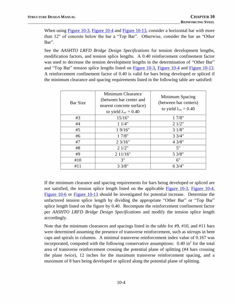
STRUCTURE DESIGN MANUAL CHAPTER 10 __________________________________________________________________ REINFORCING STEEL
10-4
When using Figure 10-3, Figure 10-4 and Figure 10-13, consider a horizontal bar with more
than 12" of concrete below the bar a “Top Bar”. Otherwise, consider the bar an “Other
Bar”.
See the AASHTO LRFD Bridge Design Specifications for tension development lengths,
modification factors, and tension splice lengths. A 0.40 reinforcement confinement factor
was used to decrease the tension development lengths in the determination of “Other Bar”
and “Top Bar” tension splice lengths listed on Figure 10-3, Figure 10-4 and Figure 10-13.
A reinforcement confinement factor of 0.40 is valid for bars being developed or spliced if
the minimum clearance and spacing requirements listed in the following table are satisfied:
Bar Size
Minimum Clearance
(between bar center and
nearest concrete surface)
to yield rc = 0.40
Minimum Spacing
(between bar centers)
to yield rc = 0.40
#3 15/16" 1 7/8"
#4 1 1/4" 2 1/2"
#5 1 9/16" 3 1/8"
#6 1 7/8" 3 3/4"
#7 2 3/16" 4 3/8"
#8 2 1/2" 5"
#9 2 11/16" 5 3/8"
#10 3" 6"
#11 3 3/8" 6 3/4"
If the minimum clearance and spacing requirements for bars being developed or spliced are
not satisfied, the tension splice length listed on the applicable Figure 10-3, Figure 10-4,
Figure 10-6 or Figure 10-13 should be investigated for potential increase. Determine the
unfactored tension splice length by dividing the appropriate “Other Bar” or “Top Bar”
splice length listed on the figure by 0.40. Recompute the reinforcement confinement factor
per AASHTO LRFD Bridge Design Specifications and modify the tension splice length
accordingly.
Note that the minimum clearances and spacings listed in the table for #9, #10, and #11 bars
were determined assuming the presence of transverse reinforcement, such as stirrups in bent
caps and spirals in columns. A minimal transverse reinforcement index value of 0.167 was
incorporated, computed with the following conservative assumptions: 0.40 in2 for the total
area of transverse reinforcement crossing the potential plane of splitting (#4 bars crossing
the plane twice), 12 inches for the maximum transverse reinforcement spacing, and a
maximum of 8 bars being developed or spliced along the potential plane of splitting.
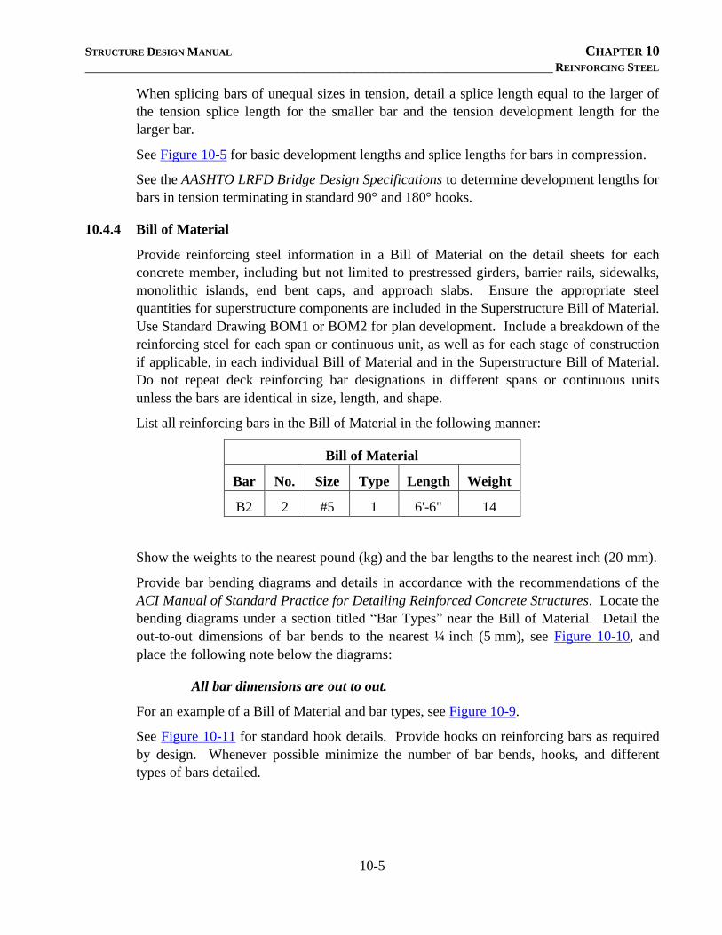
STRUCTURE DESIGN MANUAL CHAPTER 10 __________________________________________________________________ REINFORCING STEEL
10-5
When splicing bars of unequal sizes in tension, detail a splice length equal to the larger of
the tension splice length for the smaller bar and the tension development length for the
larger bar.
See Figure 10-5 for basic development lengths and splice lengths for bars in compression.
See the AASHTO LRFD Bridge Design Specifications to determine development lengths for
bars in tension terminating in standard 90° and 180° hooks.
10.4.4 Bill of Material
Provide reinforcing steel information in a Bill of Material on the detail sheets for each
concrete member, including but not limited to prestressed girders, barrier rails, sidewalks,
monolithic islands, end bent caps, and approach slabs. Ensure the appropriate steel
quantities for superstructure components are included in the Superstructure Bill of Material.
Use Standard Drawing BOM1 or BOM2 for plan development. Include a breakdown of the
reinforcing steel for each span or continuous unit, as well as for each stage of construction
if applicable, in each individual Bill of Material and in the Superstructure Bill of Material.
Do not repeat deck reinforcing bar designations in different spans or continuous units
unless the bars are identical in size, length, and shape.
List all reinforcing bars in the Bill of Material in the following manner:
Bill of Material
Bar No. Size Type Length Weight
B2 2 #5 1 6'-6" 14
Show the weights to the nearest pound (kg) and the bar lengths to the nearest inch (20 mm).
Provide bar bending diagrams and details in accordance with the recommendations of the
ACI Manual of Standard Practice for Detailing Reinforced Concrete Structures. Locate the
bending diagrams under a section titled “Bar Types” near the Bill of Material. Detail the
out-to-out dimensions of bar bends to the nearest ¼ inch (5 mm), see Figure 10-10, and
place the following note below the diagrams:
All bar dimensions are out to out.
For an example of a Bill of Material and bar types, see Figure 10-9.
See Figure 10-11 for standard hook details. Provide hooks on reinforcing bars as required
by design. Whenever possible minimize the number of bar bends, hooks, and different
types of bars detailed.
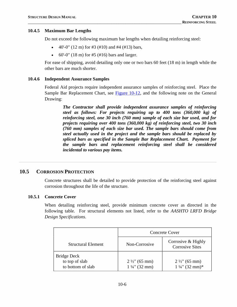
STRUCTURE DESIGN MANUAL CHAPTER 10 __________________________________________________________________ REINFORCING STEEL
10-6
10.4.5 Maximum Bar Lengths
Do not exceed the following maximum bar lengths when detailing reinforcing steel:
• 40'-0" (12 m) for #3 (#10) and #4 (#13) bars,
• 60'-0" (18 m) for #5 (#16) bars and larger.
For ease of shipping, avoid detailing only one or two bars 60 feet (18 m) in length while the
other bars are much shorter.
10.4.6 Independent Assurance Samples
Federal Aid projects require independent assurance samples of reinforcing steel. Place the
Sample Bar Replacement Chart, see Figure 10-12, and the following note on the General
Drawing:
The Contractor shall provide independent assurance samples of reinforcing
steel as follows: For projects requiring up to 400 tons (360,000 kg) of
reinforcing steel, one 30 inch (760 mm) sample of each size bar used, and for
projects requiring over 400 tons (360,000 kg) of reinforcing steel, two 30 inch
(760 mm) samples of each size bar used. The sample bars should come from
steel actually used in the project and the sample bars should be replaced by
spliced bars as specified in the Sample Bar Replacement Chart. Payment for
the sample bars and replacement reinforcing steel shall be considered
incidental to various pay items.
10.5 CORROSION PROTECTION
Concrete structures shall be detailed to provide protection of the reinforcing steel against
corrosion throughout the life of the structure.
10.5.1 Concrete Cover
When detailing reinforcing steel, provide minimum concrete cover as directed in the
following table. For structural elements not listed, refer to the AASHTO LRFD Bridge
Design Specifications.
Concrete Cover
Structural Element Non-Corrosive Corrosive & Highly
Corrosive Sites
Bridge Deck
to top of slab
to bottom of slab
2 ½" (65 mm)
1 ¼" (32 mm)
2 ½" (65 mm)
1 ¼" (32 mm)*
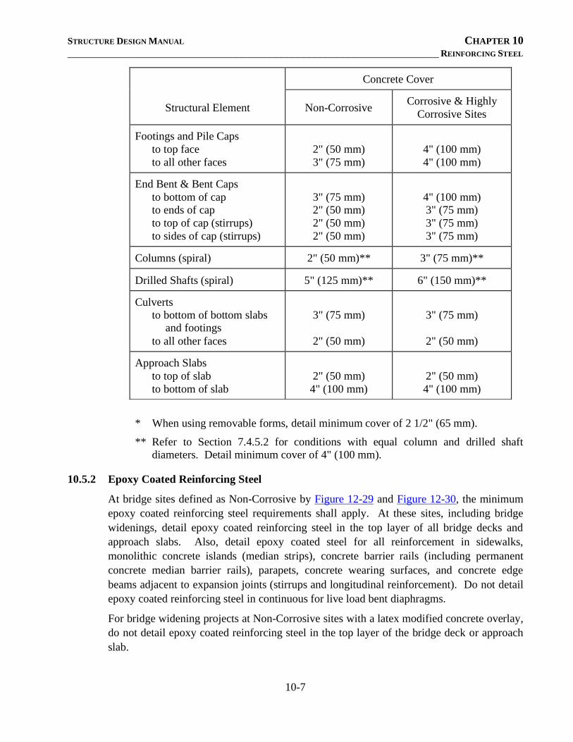
STRUCTURE DESIGN MANUAL CHAPTER 10 __________________________________________________________________ REINFORCING STEEL
10-7
* When using removable forms, detail minimum cover of 2 1/2" (65 mm).
** Refer to Section 7.4.5.2 for conditions with equal column and drilled shaft
diameters. Detail minimum cover of 4" (100 mm).
10.5.2 Epoxy Coated Reinforcing Steel
At bridge sites defined as Non-Corrosive by Figure 12-29 and Figure 12-30, the minimum
epoxy coated reinforcing steel requirements shall apply. At these sites, including bridge
widenings, detail epoxy coated reinforcing steel in the top layer of all bridge decks and
approach slabs. Also, detail epoxy coated steel for all reinforcement in sidewalks,
monolithic concrete islands (median strips), concrete barrier rails (including permanent
concrete median barrier rails), parapets, concrete wearing surfaces, and concrete edge
beams adjacent to expansion joints (stirrups and longitudinal reinforcement). Do not detail
epoxy coated reinforcing steel in continuous for live load bent diaphragms.
For bridge widening projects at Non-Corrosive sites with a latex modified concrete overlay,
do not detail epoxy coated reinforcing steel in the top layer of the bridge deck or approach
slab.
Concrete Cover
Structural Element Non-Corrosive Corrosive & Highly
Corrosive Sites
Footings and Pile Caps
to top face
to all other faces
2" (50 mm)
3" (75 mm)
4" (100 mm)
4" (100 mm)
End Bent & Bent Caps
to bottom of cap
to ends of cap
to top of cap (stirrups)
to sides of cap (stirrups)
3" (75 mm)
2" (50 mm)
2" (50 mm)
2" (50 mm)
4" (100 mm)
3" (75 mm)
3" (75 mm)
3" (75 mm)
Columns (spiral) 2" (50 mm)** 3" (75 mm)**
Drilled Shafts (spiral) 5" (125 mm)** 6" (150 mm)**
Culverts
to bottom of bottom slabs
and footings
to all other faces
3" (75 mm)
2" (50 mm)
3" (75 mm)
2" (50 mm)
Approach Slabs
to top of slab
to bottom of slab
2" (50 mm)
4" (100 mm)
2" (50 mm)
4" (100 mm)
STRUCTURE DESIGN MANUAL CHAPTER 10 __________________________________________________________________ REINFORCING STEEL
10-8
At bridge sites defined as Corrosive and Highly Corrosive by Figure 12-29 and Figure 12-
30, including bridge widenings with or without a latex modified concrete overlay, detail
epoxy coated steel for all reinforcement in cast-in-place concrete elements. In addition,
place the following note on the plans:
All bar supports used in the (barrier rail, parapet, sidewalk, deck, bent caps,
columns, pile caps, footings) and all incidental reinforcing steel shall be epoxy
coated in accordance with the Standard Specifications.
Do not detail epoxy coated reinforcing steel in prestressed concrete members.
For precast and cast-in-place culverts located east of the Corrosive (blue) line in Figure
12-29, detail epoxy coated reinforcing steel for all reinforcement and bar supports.
STRUCTURE DESIGN - DESIGN MANUAL
______________________________________________________________________________
11-1
CHAPTER 11
BRIDGE LAYOUT
11-1 General
Structure lengths, widths, and clearances shall be in agreement with the State of
North Carolina, Department of Transportation, Division of Highways, Bridge
Policy. Also, refer to the Structure Recommendations and the Policy and
Procedure Manual.
In general, end bent slopes shall be 1½:1 in fill sections and 2:1 in cut and partial
cut sections unless recommended otherwise by the Geotechnical Engineering
Unit. In Divisions 1, 2 and 3, consult with the Geotechnical Engineering Unit for
the recommended end bent slopes prior to laying out the bridge.
__________________________________________________________________
11-2 Stream Crossings
The minimum grade on a structure shall be 0.2%. Any proposed grade less than
0.2% shall be discussed with the Roadway Design Unit.
The minimum clearance between the bottom of the beams or girders and the
design high water elevation shown on the Bridge Survey Report should be 2 feet
(600 mm) for all interstate and arterial roads and 1 foot (300 mm) for all other
roads.
If practical, skewed bridges on horizontal curves with a repetitious span
arrangement should have all bent worklines set at a constant skew angle at their
point of intersection with the curve.
Slopes shall be normal to the end bent cap. Final consideration of the rate of slope
and slope protection will depend upon the Hydraulic Design.
The Hydraulics Unit computes the span lengths based on the details of
Figures 11-1 through 11-3. In general, a 1 foot (300 mm) minimum earth berm
shall be used.
Changes to grade, span arrangement or superstructure type that would affect the
waterway opening beneath the structure should not be made without first
obtaining approval from the Hydraulics Unit.
__________________________________________________________________
11-3 Grade Separations
End bent slopes should be normal to the ditch beneath the structure unless specific
conditions dictate otherwise. A 1 foot (300 mm) wide berm 1'-6" (450 mm) above
STRUCTURE DESIGN - DESIGN MANUAL CHAPTER 11
________________________________________________________________ BRIDGE LAYOUT
11-2
the bottom of cap shall be provided. In a combination cut and fill slope, a 3 foot
(1.0 m) berm normal to the cut slope should be provided at the toe of the fill. This
berm is not required when slope protection is used and/or where 2:1 slopes are
used. See Figure 11-4 for berm details.
When slope protection is used, the berm shall be sloped away from and normal to
the cap at a rate of ½ in/ft (50 mm/m). The proper berm width should be used in
determining the length of bridges. The berm widths should be computed for both
ends of both end bents. These berm widths and elevations should be shown on the
General Drawing and on the slope protection standard drawings.
The toe of the slope should intersect the centerline of the ditch shown on the
Structure Recommendations.
Consult with the Roadway Design Unit when the vertical clearance does not meet
the requirements as provided in the Structure Recommendations and the NCDOT
Bridge Policy.
__________________________________________________________________
11-4 Railroad Overheads
Structures over railroads must provide horizontal clearances that meet the
approval of the applicable railway company and shall be in conformity with the
Federal Aid Policy Guide. Figure 11-5 shall be used to set the bridge length for
both CSX and Norfolk Southern Railroads. These clearances may be changed to
reflect individual site conditions as requested by the railroad, provided they meet
the criteria outlined in the Policy Guide. The Policy and Procedure Manual should
be used as a guide in laying out the structure prior to submission to the railway
company for their approval. All span arrangements over Railroad tracks should be
reviewed and approved by the Assistant Bridge Design Engineer for Railroad
Coordination. In general, horizontal clearance for the use of off track equipment
should be provided on one side of the track.
Consult with the Roadway Design Unit when the vertical clearance does not meet
the requirements as provided in the Structure Recommendations and the NCDOT
Bridge Policy.
In fill sections, end bent slopes should be normal to the end bent cap, and in cut
and partial cut sections, slopes should be normal to the railway ditch. The location
of the toe of the slope should conform to the Federal Aid Policy Guide.
A minimum berm of 1 foot (300 mm) width normal to the end bent cap and 1'-6"
(450 mm) above the bottom of the end bent cap shall be provided in front of the
end bents.
Unless otherwise specified by the Railroad, slope protection shall be used for
railroad overheads.
STRUCTURE DESIGN - DESIGN MANUAL CHAPTER 11
________________________________________________________________ BRIDGE LAYOUT
11-3
When slope protection is used, the berm shall be sloped away from and normal to
the cap at a rate of ½ in/ft (50 mm/m). The proper berm width shall be used in
determining the length of bridges. The berm widths shall be computed for both
ends of both end bents. These berm widths and elevations shall be shown on the
General Drawing and on the slope protection standard drawings.
In order to eliminate railroad shoring, drilled piers shall be used for the foundation
of post and beam bents adjacent to railways.
Crashwalls should be considered in accordance with Section 7-10 of this manual.
__________________________________________________________________
11-5 Bridges on Horizontal Curve
The following information shall be included in the superstructure and approach
slab drawings for horizontally curved bridges:
• Dimensions along the bent control line from the workline to each gutterline.
• Arc offset dimensions for the outside edge of superstructure for each span.
These chord-to-arc ordinates shall be at 5 foot (1.5 m) intervals about the
span’s midpoint.
• Arc offset dimensions for longitudinal construction joints, if applicable.
• Short chord at the centerline survey for each span with the chord length and
the intersection angle between the chord and the centerline of joint.
A long chord layout should be shown on the General Drawing. See Section
5.1.2.5 “Long Chord Layout” in this manual.
__________________________________________________________________
11-6 Pedestrian Bridges
Structures for pedestrian traffic shall meet the criteria set forth by the AASHTO
Guide Specifications for Design of Pedestrian Bridges.
For submission of plans to FHWA where required, refer to the Policy and
Procedure Manual.

STRUCTURE DESIGN - DESIGN MANUAL
______________________________________________________________________________
12-1
CHAPTER 12
MISCELLANEOUS
12-1 Title Sheet Procedures
Title Sheet
Furnished
by
Roadway
Design Unit
When the structures are part of a project that includes roadway work, a
reproducible copy of the title sheet may be obtained from the Roadway Design
Unit. Replace the Roadway Design Project Engineer’s and Project Design
Engineer’s names with those of the Structure Design Unit’s Project Engineer and
Project Design Engineer.
__________________________________________________________________
Title Sheet
Drawn by
Structure
Design Unit
When the project does not include roadway work, the title sheet shall be
developed by the Structure Design Unit. Obtain the standard from the CADD
operator and include the following information:
• Project and TIP numbers in large numerals in left hand margin
• State, TIP and Federal Aid project numbers in the upper right hand corner
• STRUCTURE(S) or CULVERT(S) on the left side of the plan sheet
• County name in large letters
• Description of project location
• Description of type of work (when applicable, include “bicycle lanes”)
• Design designation
• Vicinity map
• Large scale map of project reflecting the beginning and ending stations of the
structure
• Shipping point
• Length of the structure along the project
• North arrow
• Total number of sheets in the plans
• Letting date
• Name of Project Design Engineer and Project Engineer
• Title sheet should be signed and sealed by the State Bridge Design Engineer
and signed by the State Highway Design Engineer.
__________________________________________________________________
12-2 Removing Existing Pavement In Order to Drive Piles In cases where the Roadway Design Unit is to remove existing pavement so that
end bent piles may be driven, the Roadway plans should state that:
STRUCTURE DESIGN - DESIGN MANUAL CHAPTER 12
________________________________________________________________ MISCELLANEOUS
12-2
The existing pavement is to be removed and the roadbed scarified to a
minimum depth of 2'-0"(610 mm) below original surface in the area where
piles are to be driven through the proposed embankment, as directed by the
Engineer. Place the following note on the General Drawing:
The existing pavement within the area of the end bent piles shall be removed
and the roadbed scarified to a minimum depth of 2'-0"(610 mm). The above notes should be modified to exclude removing the existing pavement
for gravel roads.
__________________________________________________________________
12-3 Adhesively Anchored Anchor Bolts or Dowels For certain applications, the Contractor has the option of drilling holes in the
concrete and filling them with an adhesive bonding material to install anchor bolts
or dowels rather than using cast-in-place or preset anchors.
Most applications of adhesively anchored bolts/dowels will require field testing.
For a list of these applications, as well as the level of testing required, see
Figure 12-21. These anchor bolts/dowels will be tested to a load equal to either
50% or 80% of the yield load of the anchor bolt/dowel. Place the following note
on the plans:
The Contractor may use adhesively anchored [anchor bolts/dowels] in
place of ______________. Level ___ field testing is required, and the
yield load of the [anchor bolt/dowels] is____ kips. For Adhesively
Anchored Anchor Bolts or Dowels, See Special Provisions.
If no field testing is required, place the following note on the plans:
The Contractor may use adhesively anchored [anchor bolts/dowels] in
place of ______________. No field testing is required. For Adhesively
Anchored Anchor Bolts or Dowels, See Special Provisions.
The manufacturer will determine an embedment depth that ensures the adhesive
bonding material develops at least 125% of the yield load of the anchor bolt or
dowel. The Project Engineer, however, shall be responsible for noting any
restrictions on, or special considerations of, the embedment depth of the anchor
bolt/dowel such as a 2 inch (50 mm) minimum cover on thin concrete sections. If
it is unclear whether there is adequate concrete thickness to develop a reasonable
embedment depth, check the manufacturers’ catalogs for typical embedment
depths.
STRUCTURE DESIGN - DESIGN MANUAL CHAPTER 12
________________________________________________________________ MISCELLANEOUS
12-3
For bolts, the yield load shown on the plans should be based on the yield stress
applied to the tensile stress area of the bolt. For rebar, the yield load is based on
the yield stress applied to the cross section area of the bar.
There are a number of approved manufacturers of adhesive bonding systems;
refer to the Materials and Tests Unit’s approved products list and the respective
manufacturer’s websites.
No overhead applications of adhesively anchored anchor bolts or dowels will be
allowed.
The Special Provision for Adhesively Anchored Anchor Bolts or Dowels states
that there is no special payment for this system but that it shall be included in the
unit contract price for the several pay items.
__________________________________________________________________
12-4 Rip Rap The type of rip rap to be used for a given structure will be set by the Hydraulics
Unit. If the type required is not clear on the Hydraulic Design Report, consult the
Hydraulics Unit. Filter fabric shall typically be placed under the area covered by rip rap for all rip
rapped slopes. If filter fabric is not required, it will be indicated on the Bridge
Survey Report. Show the filter fabric on the appropriate standard drawing section
views showing a straight line between the ground line and the rip rap, denoted as
filter fabric. Show the quantity of filter fabric in square yards (square meters) on
the plans. The following three standard drawings are available and should be used in plan
development:
• RR1 - “Rip Rap Details - Skew 90 ”
• RR2 - “Rip Rap Details - Skew = 90 ”
• RR3 - “Rip Rap Details - Skew 90 ” The Standards are drawn to show general details. Some modification may be
needed to suit a particular structure. The usual slope condition at stream crossing sites is a 1½:1 front slope and 1½:1
or flatter side slopes with the transition, if necessary, in the cone. The general
intention is not to place rip rap on a slope flatter than 2:1 slope; therefore, the
roadway approach slopes flatter than 2:1 should be transitioned to 2:1 before the
rip rap limits are reached. Rip rap shall be provided on slopes flatter than 2:1 on
both the front and side slopes in some unusual cases, such as bridges over lakes. In all cases where rip rap is specified, include the rip rap in tons (metric tons), in
the structure contract. To convert square yards (square meters) to tons (metric
STRUCTURE DESIGN - DESIGN MANUAL CHAPTER 12
________________________________________________________________ MISCELLANEOUS
12-4
tons), multiply by 0.90 for a 2 foot (0.98 for a 600 mm) layer of rip rap. See
Figure 12-22.
__________________________________________________________________
12-5 Slope Protection Slope protection shall be used beneath all grade separations. Unless otherwise
specified by the Railroad, slope protection shall be used for railroad overheads.
An aid for calculating concrete slope protection quantity is provided as Figure
12-23. When slope protection and a crashwall are detailed on the plans, provide a
concrete swale behind the crashwall as detailed in Figure 12-24. In general, dual bridges with median widths of 46 feet (14 m) or less shall receive
continuous slope protection between the bridges. See Standards SP1 and SP2 for slope protection details. When using the standard
drawings, delete the options and details that are not allowed. Alternate “B” for
stone slope protection shall be considered for grade separations with 2:1 end bent
slopes in rural, unpopulated areas only. Filter fabric shall typically be placed
under stone slope protection. Show the quantity of filter fabric in square yards
(square meters) on the plans.
To facilitate proper location of the toe of slope prior to construction of the
roadway ditches under the bridge, show the elevations of the toe on Standard
Drawing SP2. See Figure 12-25 for additional illustrations. This toe of slope
represents the permitted construction joint shown on Standard Drawing SP1 and
on Roadway Standard 610.03. Also, show the offset distance from the survey line
under the bridge to the toe of slope on Standard Drawing SP2.
Show the berm width and elevation at each end of the end bent cap on the General
Drawing and Standard Drawing SP2.
To facilitate proper grading of fill and construction of slope protection, show the
station, elevation and offset of the slope pivot points on Standard Drawing SP2.
Use Figure 12-25a to determine this information. In some cases, the slope pivot
point is dependent on the location of the calculated end of wing. See Section
7.2.4 – End Bent Wingwalls for guidance regarding wing lengths.
__________________________________________________________________
12-6 Plans for Falsework and Forms When preparing plans including cast-in-place deck slabs, hammerhead bents, arch
culverts, box culverts with a top slab thickness of 18 inches (455 mm) or greater,
or other special structures, place the following note on the plans:
STRUCTURE DESIGN - DESIGN MANUAL CHAPTER 12
________________________________________________________________ MISCELLANEOUS
12-5
Detailed drawings for falsework and forms for this ________ shall be
submitted. See Sheet SN (Sheet SNSM).
__________________________________________________________________
12-7 Temporary Structures On all temporary structures, place an asphalt wearing surface for traction. This
surface could be the same as that used on the detour approaches. When there is roadway work on the project, the alignment for the temporary
structures should be coordinated with the Roadway Design Unit. For projects
without roadway work, the alignment shall be shown on the plans, preferably in
the Location Sketch. For grade separations, the specified length of the temporary bridge should be the
same length as the permanent bridge.
__________________________________________________________________
12-8 Providing Access Facilities on New Bridges For bridges where portions of the structure are inaccessible from the bridge deck
or below, maintenance and inspection access details shall be included in the plans.
These details may include walkways, platforms, or ladders. The following criteria shall be used as a guide in determining which bridges
require access facilities: • Structures on which mechanical or electrical devices that require periodic
maintenance or replacement are installed.
• Bridges with a vertical underclearance of 35 feet (10.7 m) or greater and an
out-to-out deck width equal to or greater than that shown in Figure 12-26.
• Bridges over water or marshland that have an out-to-out deck width equal to
or greater than that shown in Figure 12-26.
• For bridges with sidewalks that may require access facilities, the width of
each sidewalk should be subtracted from the values shown in Figure 12-26 to
determine the permissible out-to-out deck width.
• For bridges not meeting the criteria shown in Figure 12-26, the Bridge
Maintenance Unit should be contacted for their recommendations.
• Out-to-out deck widths shown in Figure 12-26 shall be reduced for skewed
bridges. The final decision as to the need and type of access facility should be made in
consultation with the Bridge Maintenance Unit. All access facilities shall meet
OSHA requirements for structural size and safety criteria.
__________________________________________________________________
STRUCTURE DESIGN - DESIGN MANUAL CHAPTER 12
________________________________________________________________ MISCELLANEOUS
12-6
12-9 Shoring Adjacent to Existing Bridges When constructing a new or temporary bridge adjacent to an existing bridge,
consideration must be given to the need for temporary shoring. For grade separations, the Structure Design Project Engineer will coordinate with
the Roadway Design Unit and the Geotechnical Engineering Unit to determine the
shoring requirements. If shoring is required, Structure Design will provide
Roadway Design with a detail of the end bent slopes of the new bridge with the
existing slope shown in dashed lines. For the note to be placed on the General
Drawing, see Section 5.2.5 – Excavation and Shoring. For stream crossings, the Structure Design Project Engineer will coordinate with
the Geotechnical Engineering Unit to determine the shoring requirements. If
shoring is required and there is a pay item for “Temporary Shoring” in the
Roadway plans, the shoring quantity will be included in the Roadway plans. If
there is not a Roadway pay item, include a square foot (square meter) pay item for
“Temporary Shoring” on the Structure plans. For the note to be placed on the
General Drawing, see Section 5.2.5 – Excavation and Shoring. Temporary Shoring for the Maintenance of Traffic shall be detailed when needed
to provide lateral support to the side of an excavation or embankment parallel to
an open travelway when a theoretical 2:1 or steeper slope from the bottom of the
excavation or embankment intersects the existing ground line closer than five feet
from the edge of pavement of an open travelway. Shoring required for foundation
or culvert excavation is considered Temporary Shoring for the Maintenance of
Traffic if it also satisfies the above requirement. The need for Temporary Shoring for Maintenance of Traffic shall be determined
through coordination with Soils and Foundation, Traffic Control, and Roadway
Design. This shoring will be shown on the Traffic Control Plans and the pay
quantity provided in the roadway plans. When this shoring is required, indicate
the shoring in the plan view of the general drawing and label it as “Temporary
Shoring for the Maintenance of Traffic. See Notes.” The beginning and ending
stations for this shoring are not required on the plans. See Section 5.2.5 –
Excavation and Shoring for the note to be placed on the General Drawing. Confer with Soils and Foundation to determine the limits and pay quantity of this
shoring. The quantity of temporary shoring to be paid for will be the actual
number of square feet (square meters) of exposed face of the shoring measured
from the bottom of the excavation or embankment to the top of the shoring, with
the upper limit not to exceed 1 foot (300 mm) above the retained ground line.
__________________________________________________________________
12-10 Foundation Excavation on Railroad Right of Way
General Details for foundation excavation on railroad right of way shall be shown in the
contract plans. Excavations may be detailed as either sloped open cuts or with
STRUCTURE DESIGN - DESIGN MANUAL CHAPTER 12
________________________________________________________________ MISCELLANEOUS
12-7
temporary shoring. When several substructure units are on the Railroad right of way, the Railroad
may only require excavation details for the units closest to the track. In this
situation, the Assistant State Bridge Design Engineer will assist in obtaining
permission from the Railroad to exclude the unnecessary excavation details from
the plans. To eliminate the need for foundation excavation for railroad crashwalls, bents
shall be located to provide 25 feet (7.62 m) horizontal clearance from the
centerline track whenever practical.
__________________________________________________________________
Shoring or
Open
Excavation
Plans
When circumstances allow an open cut excavation, provide plan and section view
details to show the limits of the excavation. The Geotechnical Engineering Unit
must be consulted to determine the maximum permissible cut slope for the soil
conditions. The plans should include the minimum distance from the centerline of
the track to the top of the nearest excavation cut slope. When temporary shoring is required, the design and plans shall be prepared in
accordance with the requirements illustrated in Figure 12-27. The plans shall
contain details of the shoring system including the size of all structural members,
connection details, embedment depth and the distance from the centerline of track
to the near face of shoring. The plans shall also include a section showing the
height of the sheeting and the track elevation in relation to the bottom of the
excavation (additional survey data may be needed in order to show this
information). The inside face of the shoring shall be a minimum of 1'-6"
(450 mm) outside the edge of the footing. Where it is not possible to design a
shoring system without struts extending through the crashwall, place the details of
Figure 12-28 on the plans. Unless prior approval is received from the Railroad, all excavations on Railroad
right of way shall be detailed with handrails. In addition, open excavations
adjacent to tracks that are located within what is termed “normal walkways” by
the Railroad shall be detailed with a walkway and handrails. Handrails shall not
be located closer than 10 feet (3 m) horizontally from the centerline of the track.
__________________________________________________________________
Design
Allowable stresses for concrete and steel shall be in accordance with the AREMA
Specifications. Railroad surcharge loads shall be computed using the equation for
a continuous strip of surcharge load from the AREMA Specification and shall be
based on a Cooper’s E80 live load model. The Geotechnical Engineering Unit is
to be consulted in determining soil pressures, possible pile or sheeting
penetrations, and slope stability of the highway approach fills and the open
foundation excavations.
STRUCTURE DESIGN - DESIGN MANUAL CHAPTER 12
________________________________________________________________ MISCELLANEOUS
12-8
Coordination with the Geotechnical Engineering Unit may also be required to
ensure that the Foundation Recommendations do not detail the footing at an
elevation that interferes with the railroad ditch. Plans prepared for shoring or open cut foundation excavation shall provide for the
possibility of spread footings being lowered up to 3 feet (1 m).
__________________________________________________________________
Pay Items When the foundation excavation at a bent involves shoring that fully or partially
encloses the excavation, each affected substructure unit will require two lump
sum pay items as follows: • “Shoring For Bent _____ ”
• “Foundation Excavation For Bent _____ ” When the foundation excavation at a bent involves only an open cut, each affected
substructure unit will require one lump sum pay item as follows: • “Foundation Excavation For Bent _____ ” For a bridge that spans both a railroad and a highway or a stream, some of the
substructure units may fall outside the Railroad right of way. Pay items and
payment for “Foundation Excavation” for these units will be handled as outlined
in Section 7.5 – Foundation Excavation of this manual. For the note to be placed on the General Drawing when Railroad approval has not
been received prior to the letting, see Section 5.2.5 – Excavation and Shoring.
__________________________________________________________________
12-11 Corrosion Protection
General Corrosion protection is achieved through the use of one or more of the following
measures: Increased clear cover for reinforcing steel, epoxy coating reinforcing
steel, adding calcium nitrite corrosion inhibitor, silica fume, fly ash or granulated
blast furnace slag, specifying Class AA concrete for substructures, and limiting
the use of uncoated structural steel. Corrosion protection is used to varying degrees for bridges on or east of the
Corrosive (blue) Line of Figure 12-29 and in Divisions where significant road salt
is applied. Figure 12-30 provides a flowchart to determine the extent of corrosion
protection necessary for any bridge. In Divisions 5, 7, or 9-14, corrosion protection focuses on the bridge deck, where
mineral admixtures are added to the concrete to reduce permeability.
For Corrosive Sites, the corrosion protection is more comprehensive. Corrosive
Sites are limited to stream crossings on or east of the Corrosive (blue) Line as
STRUCTURE DESIGN - DESIGN MANUAL CHAPTER 12
________________________________________________________________ MISCELLANEOUS
12-9
defined by Figure 12-29. For these bridges, mineral admixtures may be required
in all or some of the bridge members. Additionally, calcium nitrite is specified to
increase corrosion resistance of the reinforcing steel. See Figure 12-30 for
instructions on applying the various protection systems to each location. For bridges located east of the Highly Corrosive (red) Line, all concrete will
receive at least one corrosion protection measure. For bridges located between the
Highly Corrosive (red) and Corrosive (blue) Lines of Figure 12-29, apply
corrosion protection measures and notes to only those structural elements (i.e.
prestressed concrete girder, cored slab, bent cap, column, etc,) that are located
within 15 feet (4.5 m) of mean high tide. When any structural element is within
15 feet (4.5 m) of mean high tide, all similar elements in the bridge shall receive
the same corrosion protection.
__________________________________________________________________
Corrosion
Protection
Measures
Corrosion protection measures are determined through the use of the flowchart of
Figure 12-30 and the map of Figure 12-29. The notes below shall be used as
directed by Figure 12-30. Note #1: The class AA concrete in the bridge deck shall contain fly ash or
ground granulated blast furnace slag at the substitution rate
specified in Article 1024-1 and in accordance with Articles 1024-5
and 1024-6 of the Standard Specifications. No payment will be made
for this substitution as it is considered incidental to the cost of the
Reinforced Concrete Deck Slab.
Note #2: All metallized surfaces shall receive a seal coating as specified in the
Special Provision for Thermal Sprayed Coatings (Metallization).
Note #3: Class AA concrete shall be used in all cast-in-place columns, bent
caps, pile caps, and footings, and shall contain calcium nitrite
corrosion inhibitor. For Calcium Nitrite Corrosion Inhibitor, see
Special Provisions.
Note #4: Prestressed concrete girders are designed for 0 psi (0 MPa) tension
in the precompressed tensile zone under all loading conditions.
Note #5: Precast panels shall be designed for an allowable tensile stress of
0 psi (0 MPa) in the precompressed tensile zone under all loading
conditions.
Note #6: The water/cement ratio for concrete piles shall not exceed 0.40.
Note #7: All bar supports used in the (barrier rail, parapet, sidewalk, deck,
bent caps, columns, pile caps, footings) and all incidental reinforcing
steel shall be epoxy coated in accordance with the Standard
Specifications.
Note #8: Prestressed concrete (girders, precast deck panels, cored slab units,
piles) shall contain calcium nitrite corrosion inhibitor. See Special
Provisions for Calcium Nitrite Corrosion Inhibitor.
STRUCTURE DESIGN - DESIGN MANUAL CHAPTER 12
________________________________________________________________ MISCELLANEOUS
12-10
For those elements of the structure that may undergo repeated wetting and drying
cycles due to tidal fluctuations, 5% of the portland cement shall be replaced with
silica fume. For mass concrete elements subject to repeated wetting and drying
cycles, use fly ash in lieu of silica fume. Place the note below on the General
Drawing. If precast elements require silica fume, also place the note on the
precast element sheet or standard drawing:
Note #9: The concrete in the (columns, bent caps, pile caps, footings, and/or
piles) of Bent No. ____ shall contain silica fume. Silica Fume shall
be substituted for 5% of the portland cement by weight. If the option
of Article 1024-1 of the Standard Specifications to partially
substitute Class F fly ash for portland cement is exercised, then the
rate of flay ash substitution shall be reduced to 1.0 lb (1.0 kg) of fly
ash per 1.0 lb (1.0 kg). No payment will be made for this substitution
as it is considered incidental to the various pay items. In general, metal stay-in-place forms shall not be permitted. In special situations,
such as in those channel spans of high level bridges where the use of prestressed
concrete deck panels is not feasible, removable forms shall be required.
__________________________________________________________________
Weathering
Steel and
Steel
Coatings
Weathering steel (AASHTO M270 Gr. 50W or Gr. 70W) shall not be used in
“low-level” water crossings nor “tunnel-like” grade separations. Stream
crossings that are less than 10 ft (3 m) above the normal water surface shall be
considered “low-level”. Grade separations where a depressed roadway is
bounded by abutments or retaining walls, typically found in urban areas, shall be
considered “tunnel-like”.
Concrete or fully-painted steel (i.e., AASHTO M270 Gr. 36, 50 or 70) shall be
used in lieu of weathering steel for superstructures of stream crossings, grade
separations and railroad overheads in the following counties: Brunswick Hyde
New Hanover Dare
Pender (on or East of NC 53) Tyrrell
Onslow Washington
Carteret Chowan
Craven (on or east of US 17) Perquimans
Jones (on or east of US 17) Pasquotank
Pamlico Camden
Beaufort Currituck
__________________________________________________________________
STRUCTURE DESIGN - DESIGN MANUAL CHAPTER 12
________________________________________________________________ MISCELLANEOUS
12-11
Thermal
Sprayed
Coatings
When thermal sprayed coatings are required, place the applicable note(s) on the
plans stating the type of alloy required and its required thickness. For most
applications the alloy and thickness will be prescribed in the Special Provision.
However, for some applications the alloy and thickness are required as outlined
below.
Steel Piles in Corrosive Environments
For steel piles in a corrosive environment, 99.5 percent Aluminum (W-Al-1350)
and a seal coat is required. Place the following note on the plans:
Apply an 8 mil thick 1350 Aluminum (W-Al-1350) thermal spray coating
with a 0.5 mil thick seal coat to the piles, in accordance with the Thermal
Sprayed Coatings Special Provision and Section 442 of the Standard
Specifications. For Thermal Sprayed Coatings, see Special Provisions.
System 1 Paint is required on the portion of the steel pile (H or pipe piles) that is
embedded in concrete. Place the following note on the plans:
After driving the piles, apply 1 coat each of 1080-12 Brown and 1080-12
Gray paint to the embedded section of the metallized pile prior to concrete
embedment in accordance with Section 442 of the Standard Specifications.
In corrosive sites, exposed steel piles shall be used for fender systems only, shall
contain 0.2% copper, be metallized and have a seal coat. Place the following note
on the detail sheet:
Steel piles for fender systems shall contain 0.2% copper, be metallized and
have a seal cost. For Thermal Sprayed Coatings, see Special Provisions.
Steel Girders
When thermal sprayed coatings are used on girders an approved seal coat is
required. Place the following note on the plans:
Apply an 8 mil thick 99.99 percent Zinc (W-Zn-1) thermal spray coating
with a 0.5 mil thick seal coat to all girder surfaces in accordance with the
Thermal Sprayed Coatings Special Provision and Section 442 of the
Standard Specifications. Prior to application, create a companion coupon
for approval by the Engineer. For Thermal Sprayed Coatings, see Special
Provisions.
STRUCTURE DESIGN - DESIGN MANUAL CHAPTER 12
________________________________________________________________ MISCELLANEOUS
12-12
Aesthetic Considerations
For applications where aesthetics are a major concern, add the following note to
the plans:
Prior to beginning metallization, the Contractor will provide metallized
samples to the Engineer for approval.
__________________________________________________________________
12-12 Retaining Walls
Reinforced
Concrete
Retaining
Walls
Use a minimum footing depth of 12 in (300 mm) for all retaining walls. For other
design criteria, see Section 2.1.2.2 – Lateral Earth Pressure.
Provide vertical contraction joints in the wall at approximately 30 ft (9 m) centers
and expansion joints at approximately 90 ft (27 m) centers. Dovetail the
expansion joints and use 1 in (25 mm) expansion joint material up to within 12 in
(300 mm) of the top of the wall. Provide a 6 in (152 mm) plastic waterstop to
extend from the construction joint in the footing to 6 in (150 mm) below the top
of the wall. Plastic waterstops are not required in retaining walls adjacent to a
stream. Consider special construction requirements, such as temporary sheeting that may
require Special Provisions or notations on the plans.
__________________________________________________________________
Proprietary
Retaining
Wall and
Abutment
Structures
Proprietary retaining wall and abutment structures (i.e., Reinforced Earth,
Retained Earth, or Hilfiker Wall) are included in the Structure plans. In the case
where there are no bridges or culverts on the project, the proprietary retaining
wall and abutment structure will be the only structure in the Structure plans.
Provide a sheet in the plans showing the plan and elevations of the proposed
retaining walls. After the letting, the Geotechnical Engineering Unit receives proprietary wall
plans from the wall manufacturer. The Geotechnical Engineering Unit will check
the wall for bearing capacity, sliding, overturning and other items pertaining to
soil mechanics. The Structure Design Project Engineer will receive this package
from the Geotechnical Engineering Unit to check the structural elements of the
wall. Place the following note on the plans:
For MSE Retaining Walls, see Special Provisions.
STRUCTURE DESIGN - DESIGN MANUAL CHAPTER 12
________________________________________________________________ MISCELLANEOUS
12-13
Show a sketch on the plans indicating the structure excavation limits for the
installation of the walls. See Figures 12-31 and 12-32 for examples of appropriate
sketches for various types of walls.
__________________________________________________________________
12-13 Closed Structure Drainage System
When required by the Hydraulics Unit, a closed structure drainage system shall be
detailed on the plans. Payment for the drainage system shall be shown on the
Total Bill of Material at the lump sum price for “Structure Drainage System”. For
structure drainage system details, see Figures 12-33 through 12-35.
Place the following notes on the plans:
For Structure Drainage System, see Special Provisions.
The Contractor shall submit a plan for the drainage system, including, but
not limited to, attachments to the bridge, scupper and inlet grate details,
scupper support system, pipe alignment and pipe lengths, and all necessary
fittings, elbows, wyes, adapters, guides and joints.
Shear studs or stirrups may be cut as approved by the Engineer to avoid
interference with the bridge scupper.
Locate scuppers in the Plan of Spans as directed by the Hydraulics Unit. Provide
reinforcement around the scupper as detailed on Standard BS2, “Bridge Scupper
Details.” Size inlet grates based on overhang and flange widths and
recommendations from the Hydraulics Unit. Locate corresponding downspouts
on an elevation view of the drainage system. Provide a general schematic
drawing of the system but do not detail pipe lengths, fittings, elbows, or other
such details. See Figure 12-33.
Detail a longitudinal drain pipe with a minimum slope of 0.5% or as otherwise
directed by the Hydraulics Unit. Typically, this drain pipe will be located
immediately inside an exterior girder. Provide expansion joints in the drain pipes
at a maximum spacing of 25 feet (7.5 m). Detail the location of pipe hangers and
concrete inserts at a maximum spacing of 6 feet (2 m). Reduce this spacing to a
maximum of 5 feet (1.5 m) surrounding each downspout and pipe expansion joint.
A detail of the concrete insert placement is provided in Figure 12-34. Detail a
cleanout at each end of each longitudinal drain pipe and along the column
downspout as detailed in Figure 12-33.
Include section views on the plans that show the position of the drain pipe relative
to the diaphragms as shown in Figure 12-35. The cleanouts over the bent should
be aligned to avoid interference with the bent diaphragm.
If a junction box is required to accept the drainage from the system, coordinate
with the Roadway Design Unit to locate the junction box. Place the following
note on the plans:
STRUCTURE DESIGN - DESIGN MANUAL CHAPTER 12
________________________________________________________________ MISCELLANEOUS
12-14
See Roadway Plans for details and pay item for junction box at approximate
Station _______.
__________________________________________________________________
12-14 Sound Barrier Walls Pile panel sound barrier walls shall be in accordance with Standards SBW1 and
SBW2 and the Special Provisions. The wall components shall be designed for the
wind pressure as determined by the Exposure Category map of Figure 12-36.
Options and details shall be provided on the standard drawings to allow the use of
either a 10 foot (3.1 m), or 15 foot (4.6 m) panel. The appropriate pile selection table from Standard SBW1 should be placed on the
plans. The dead load, ice load, and wind loads have been considered in the panel
and pile design. For walls subject to any additional loadings, the pile and panel
shall be designed on a case by case basis. In addition, walls exceeding 29 feet
(8.840 m) in height shall be designed on a case by case basis.
The Geotechnical Engineering Unit will determine the drilled pier lengths to be
shown on Standard SBW1. Calculate the soil loads based on Figure 12-37,
excluding the weight of the pile and drilled pier. Submit the loads and a copy of
the Roadway Plan sheet that locates the wall to the Soils and Foundation Unit. The required horizontal reinforcement in the precast panels, as determined by
Figure 12-37, should be detailed on Standard SBW2 and the quantity tables for
one precast panel shall be completed. The number and size of panels does not
need to be computed; however, the estimated area, as computed from the
Roadway plans, of the wall should be reported on Standard SBW2. The completed standard drawings for the wall shall be transmitted to the Roadway
Design Unit for inclusion with the wall layout and envelope in the Roadway
plans.
12-15 Electrical Conduit System
The design of the Electrical Conduit System is categorized by its attachment to
the superstructure. The three options are attachment to SIP forms, precast deck
panels, or overhangs. Use the overhang option only when designing a stream
crossing or a railroad crossing.
Every structure designed with an electrical conduit system shall use a conduit
Expansion Joint Fitting and a Transition Adapter at each end bent and an
Expansion Joint Fitting at each expansion joint in the deck. A Stabilizer should
also be detailed midway between deck expansion joints. A Deflection Coupling
is to be used only on structures on a horizontal curve that require the conduit to
bend laterally to complete the installation. When a Deflection Coupling is
required, place the following note on ECS1 or ECS1SM:
STRUCTURE DESIGN - DESIGN MANUAL CHAPTER 12
________________________________________________________________ MISCELLANEOUS
12-15
Install Deflection Coupler at each bent. See Detail “F”.
When the Electrical Conduit System is used on bridges designed for precast deck
panels, place the following note on the Precast Panel Standard PDP1:
¾” (19 mm) diameter pipe sleeve inserts shall be installed at a maximum
of 10 foot (3m) centers to accommodate the Electrical Conduit System.
See Electrical Conduit Systems Details.
Payment for the Electrical Conduit System will be as “Lump Sum”. No bill of
material for the Conduit System will be required.