Embed Size (px)
Citation preview
1/26
Structural Tech Report #1 Structural Concepts / Structural Existing Conditions Report
Table of Contents
1. Executive Summary……………………………….…….………..Page 2
2. Building Description…….………………………….…….………Page 3
2.1. Introduction…………………………………….……….…..Page 3
2.2. Structural System………………………………….…….….Page 3
2.2.1. Superstructure………………………….……………..Page 3
2.2.2. Substructure…………………………………………..Page 5
2.2.3. Connections…..………………………………………..Page 6
2.2.4. Envelope………….…………………………….……...Page 7
2.2.5. Lateral System…………………………………………Page 7
3. Design Criteria……………………….…………………………...Page 8
3.1. Design Codes…………………….…..………………………Page 8
3.2. Specifications and Standards…….…………………………Page 8
3.3. Material Strengths………………….……………………….Page 8
3.4. Gravity Loads……………………….…...………………….Page 10
3.5. Wind Loads………………………….…...………………….Page 12
3.6. Seismic Loads……………………….…..…………………..Page 16
3.7. Gravity Load Spot Check….……….….…………………..Page 18
3.8. Lateral Load Spot Check…………….……….……………Page 22
3.9. Other Design Considerations.…….………………………..Page 23
4. Appendix…………………………………………………………..Page 23
2/26
1. Executive Summary
Introduction
This report analyzes the structural procedures used to design Fordham Place in Bronx, NY.
Building Description
Fordham Place is a 15 story office / retail building that is located at 400 East Fordham Road, Bronx, NY. The 174060 sq. ft tower is going to tie into an existing 6 story SEARS building. In the new tower, structural engineers used modern design, taking advantage of composite action using steel beams with a 6 ¼ “ concrete slab. The slab will be supported by 3” composite floor deck with 3” headed shear studs within the slab. Steel columns are used to transfer load to foundation, where it will be supported by a number of 150 ton piles. The main lateral resisting system is made up of steel concentrically loaded chevron braced frames.
Structural Design Code
Building Code of New York City, 2003, ASCE 7-02 Loads / Spot Checking Summary
When comparing my calculated gravity, wind, and seismic loads to those of the designer, some values will differ. Gravity loads compared very well with those of the designer while my lateral loads appear to differ by a significant amount. When doing both gravity and lateral spot checking of members, I compared capacity of members to the ultimate moments and forces. For both gravity and lateral spot checking my capacities were slightly larger than the ultimate design values. I believe the indifference in the gravity values can be attributed to designing with ASD as opposed to LRFD. Lateral indifferences can a cause of my conservative assumption of each of 3 braced frames will receive 40% of the lateral load, equally a total of 120%. It can also be attributed to the design differences between New York City Building Code and ASCE 7-02, the code that I used for my loading values.
3/26
2. Building Description
2.1. General
As you look around Bronx, NY you will notice a distinct similarity between most buildings; this being they are shorter older buildings, most less than 6 stories. Once Fordham Place is erected, it will tower over the city of Bronx, rising 15 stories above ground level. As you go up the building, its size decreases as the building steps in at the 6th floor and then again at the 15th floor. The 15 story office tower will connect into an existing 5 story brick and limestone building which will have retail space up to the second floor and a sports club on the third. The office tower base will be clad in GFRC or cast stone to match the limestone base of the existing building. The tower itself will be a panelized brick veneer system to compliment the existing building. The Tower design includes modern references to the classical detailing of the existing building (such as the cornices, cast iron mullions etc.) The floor elevations of the new building will match the existing and there will be an expansion joint separating the new and old.
2.2 Structural System
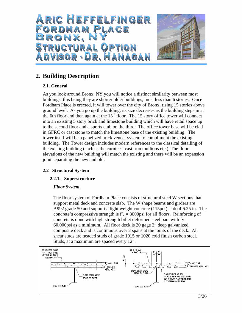
2.2.1. Superstructure
Floor System The floor system of Fordham Place consists of structural steel W sections that support metal deck and concrete slab. The W shape beams and girders are A992 grade 50 and support a light weight concrete (115pcf) slab of 6.25 in. The concrete’s compressive strength is f’c = 3000psi for all floors. Reinforcing of concrete is done with high strength billet deformed steel bars with fy = 60,000psi as a minimum. All floor deck is 20 gage 3” deep galvanized composite deck and is continuous over 2 spans at the joints of the deck. All shear studs are headed studs of grade 1015 or 1020 cold finish carbon steel. Studs, at a maximum are spaced every 12”.
4/26
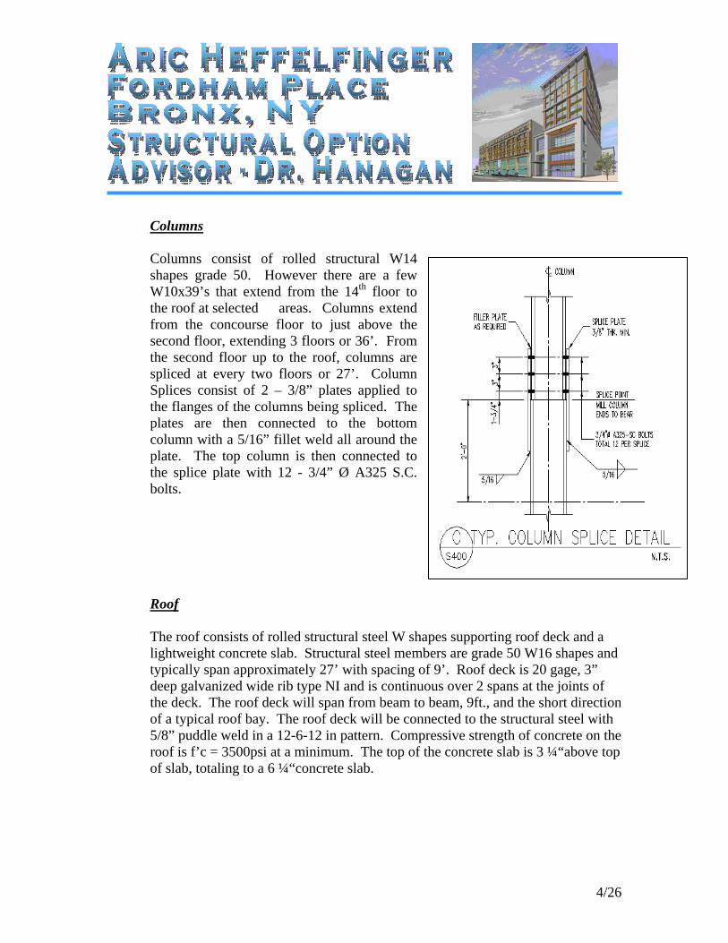
Columns Columns consist of rolled structural W14 shapes grade 50. However there are a few W10x39’s that extend from the 14th floor to the roof at selected areas. Columns extend from the concourse floor to just above the second floor, extending 3 floors or 36’. From the second floor up to the roof, columns are spliced at every two floors or 27’. Column Splices consist of 2 – 3/8” plates applied to the flanges of the columns being spliced. The plates are then connected to the bottom column with a 5/16” fillet weld all around the plate. The top column is then connected to the splice plate with 12 - 3/4” Ø A325 S.C. bolts.
Roof The roof consists of rolled structural steel W shapes supporting roof deck and a lightweight concrete slab. Structural steel members are grade 50 W16 shapes and typically span approximately 27’ with spacing of 9’. Roof deck is 20 gage, 3” deep galvanized wide rib type NI and is continuous over 2 spans at the joints of the deck. The roof deck will span from beam to beam, 9ft., and the short direction of a typical roof bay. The roof deck will be connected to the structural steel with 5/8” puddle weld in a 12-6-12 in pattern. Compressive strength of concrete on the roof is f’c = 3500psi at a minimum. The top of the concrete slab is 3 ¼“above top of slab, totaling to a 6 ¼“concrete slab.
5/26
2.2.2 Substructure
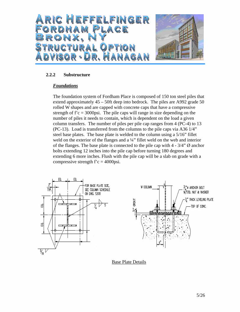
Foundations The foundation system of Fordham Place is composed of 150 ton steel piles that extend approximately 45 – 50ft deep into bedrock. The piles are A992 grade 50 rolled W shapes and are capped with concrete caps that have a compressive strength of f’c = 3000psi. The pile caps will range in size depending on the number of piles it needs to contain, which is dependent on the load a given column transfers. The number of piles per pile cap ranges from 4 (PC-4) to 13 (PC-13). Load is transferred from the columns to the pile caps via A36 1/4” steel base plates. The base plate is welded to the column using a 5/16” fillet weld on the exterior of the flanges and a ¼” fillet weld on the web and interior of the flanges. The base plate is connected to the pile cap with 4 - 3/4” Ø anchor bolts extending 12 inches into the pile cap before turning 180 degrees and extending 6 more inches. Flush with the pile cap will be a slab on grade with a compressive strength f’c = 4000psi.
Base Plate Details
6/26
2.2.3 Connections
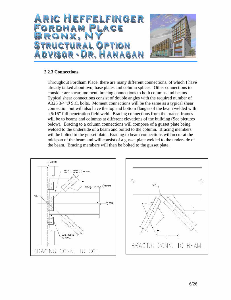
Throughout Fordham Place, there are many different connections, of which I have already talked about two; base plates and column splices. Other connections to consider are shear, moment, bracing connections to both columns and beams. Typical shear connections consist of double angles with the required number of A325 3/4”Ø S.C. bolts. Moment connections will be the same as a typical shear connection but will also have the top and bottom flanges of the beam welded with a 5/16” full penetration field weld. Bracing connections from the braced frames will be to beams and columns at different elevations of the building (See pictures below). Bracing to a column connections will compose of a gusset plate being welded to the underside of a beam and bolted to the column. Bracing members will be bolted to the gusset plate. Bracing to beam connections will occur at the midspan of the beam and will consist of a gusset plate welded to the underside of the beam. Bracing members will then be bolted to the gusset plate.
7/26
2.2.4 Enclosure
The building enclosure at Fordham Place consists of many different types. For the existing building, you will notice an older light brown brick wall with granite piers running the height of the building to interrupt the brick. At the base there currently is steel covering windows. But soon, when Fordham Place is finished with construction, it will return to display windows for retail stores. Playing off the older style building the existing structure brings, the new tower will match the light brown brick in the façade. The façade will also have sunlight gleaming off the many blue tinted glass panes. Finally, on the lower 2 floors facing Fordham Road, the building will have a glass façade enclosing a two story lobby area.
2.2.5 Lateral System
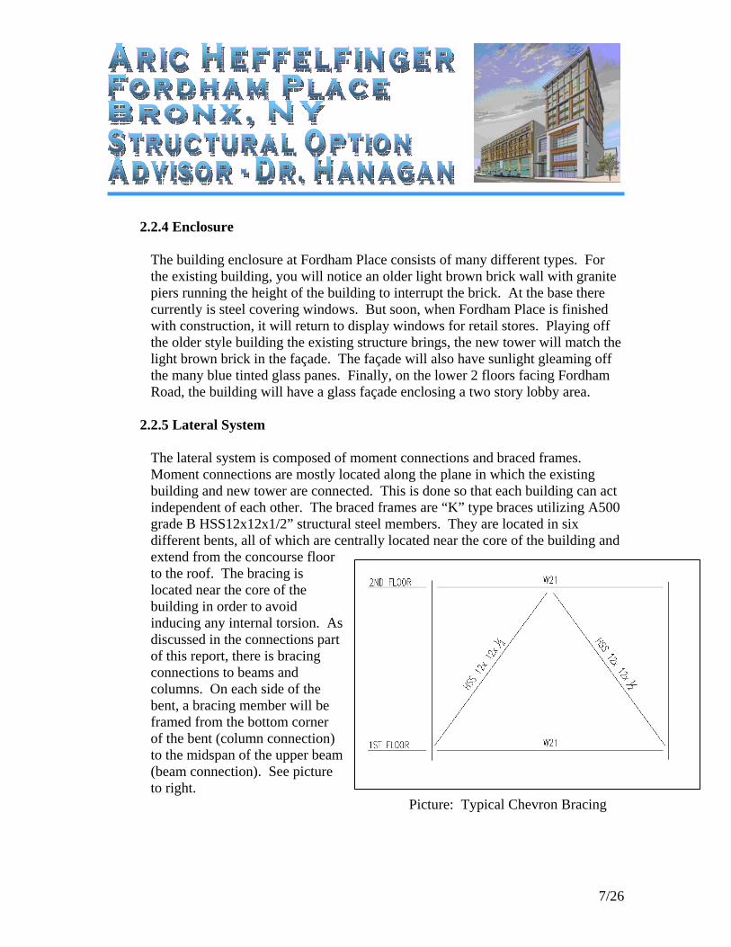
The lateral system is composed of moment connections and braced frames. Moment connections are mostly located along the plane in which the existing building and new tower are connected. This is done so that each building can act independent of each other. The braced frames are “K” type braces utilizing A500 grade B HSS12x12x1/2” structural steel members. They are located in six different bents, all of which are centrally located near the core of the building and extend from the concourse floor to the roof. The bracing is located near the core of the building in order to avoid inducing any internal torsion. As discussed in the connections part of this report, there is bracing connections to beams and columns. On each side of the bent, a bracing member will be framed from the bottom corner of the bent (column connection) to the midspan of the upper beam (beam connection). See picture to right.
Picture: Typical Chevron Bracing
8/26
3. Structural Design Criteria
3.1 Structural Design Code
The 2003 Building Code of New York City
3.2 Structural Design Specifications and Standards
Structural Concrete Design – American Concrete Institute, Building Code Requirements for Structural Concrete, ACI 318-02
Structural Steel Design – American Institute of Steel Construction, Steel Construction Manual, Allowable Stress Design Ninth Addition
Welding - American Welding Society, Structural Welding Code - Reinforcing Steel, AWS D1.4-79
Steel Deck - Design Manual for Floor Decks and Roof Decks, SDI
Masonry – American Concrete Institute, Specifications for masonry Structures, ACI 530.1
3.3 Project Material Strength
Concrete (28 day minimum compressive strength) Footings: 3000psi Slab on Grade: 4000psi Piers: 4000psi Footings: 4000psi Steel Deck Slabs (lightweight): 3500psi
Lightweight Concrete: 115pcf Normal weight Concrete: 145pcf
Steel Reinforcement
Reinforcing Bars – ASTM A615 or A706 Grade 60 (Fy = 60,000psi min) Welded Wire Fabric – ASTM 185
9/26
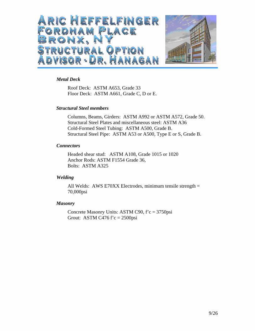
Metal Deck
Roof Deck: ASTM A653, Grade 33 Floor Deck: ASTM A661, Grade C, D or E.
Structural Steel members
Columns, Beams, Girders: ASTM A992 or ASTM A572, Grade 50. Structural Steel Plates and miscellaneous steel: ASTM A36 Cold-Formed Steel Tubing: ASTM A500, Grade B. Structural Steel Pipe: ASTM A53 or A500, Type E or S, Grade B.
Connectors
Headed shear stud: ASTM A108, Grade 1015 or 1020 Anchor Rods: ASTM F1554 Grade 36, Bolts: ASTM A325
Welding
All Welds: AWS E70XX Electrodes, minimum tensile strength = 70,000psi
Masonry
Concrete Masonry Units: ASTM C90, f’c = 3750psi Grout: ASTM C476 f’c = 2500psi
10/26
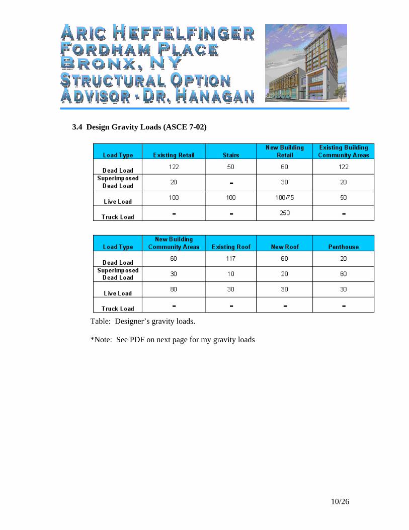
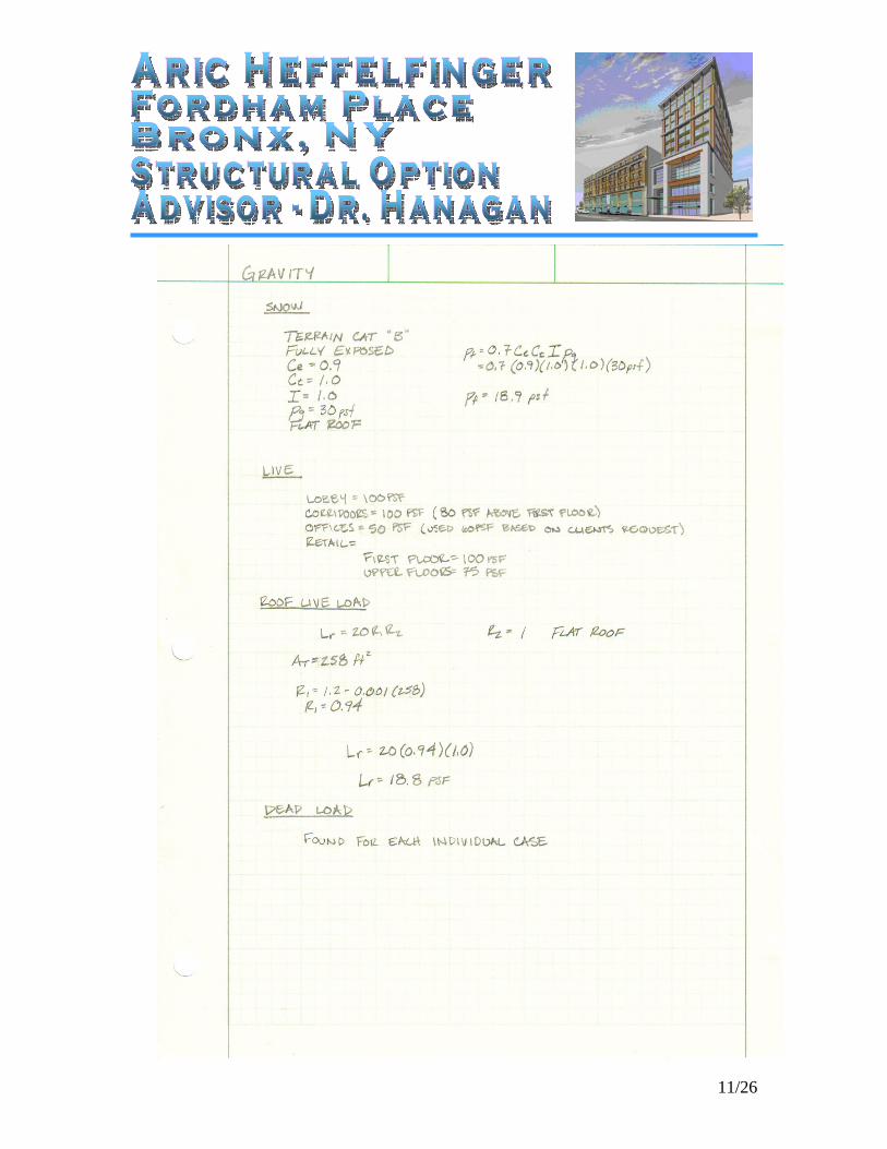
3.4 Design Gravity Loads (ASCE 7-02)
Table: Designer’s gravity loads. *Note: See PDF on next page for my gravity loads
11/26
12/26
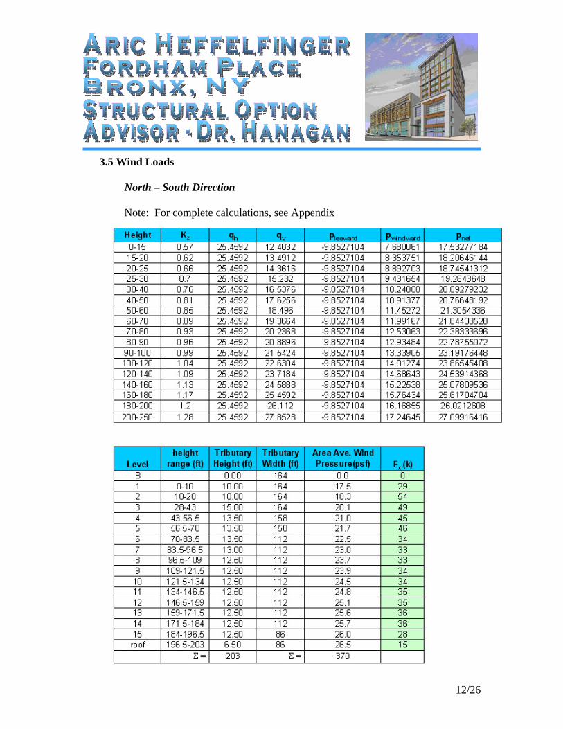
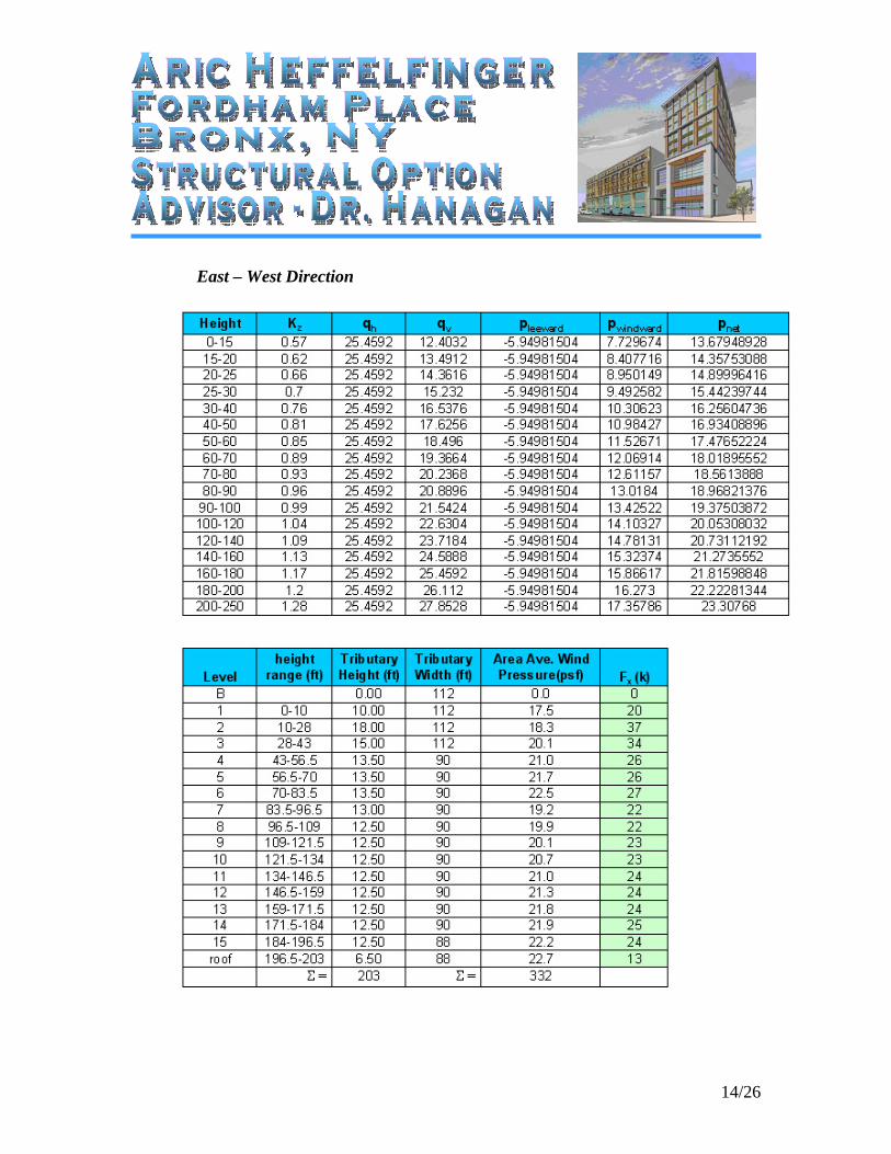
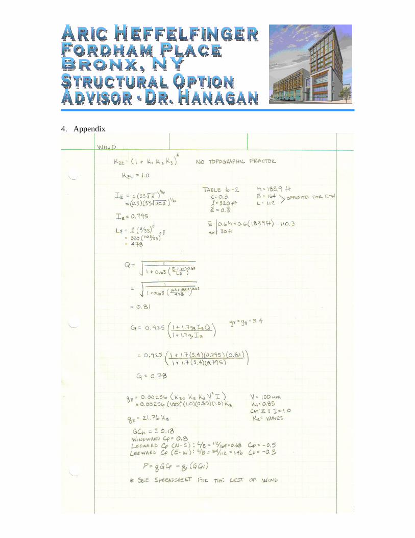
3.5 Wind Loads
North – South Direction Note: For complete calculations, see Appendix
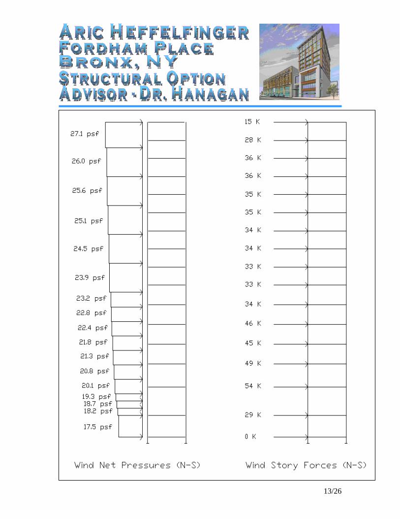
13/26
14/26
East – West Direction
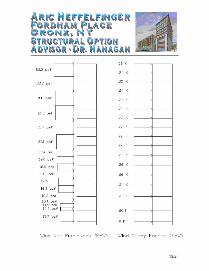
15/26
16/26
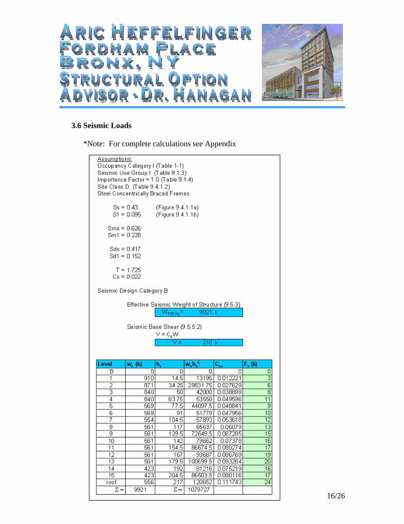
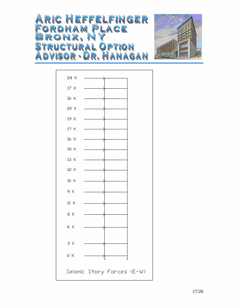
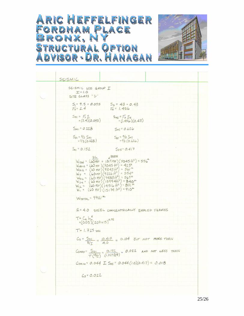
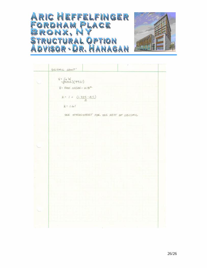
3.6 Seismic Loads
*Note: For complete calculations see Appendix
17/26
18/26
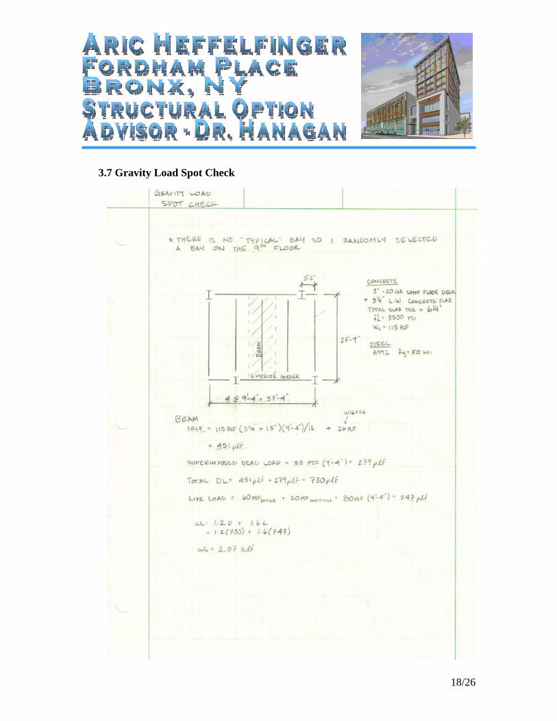
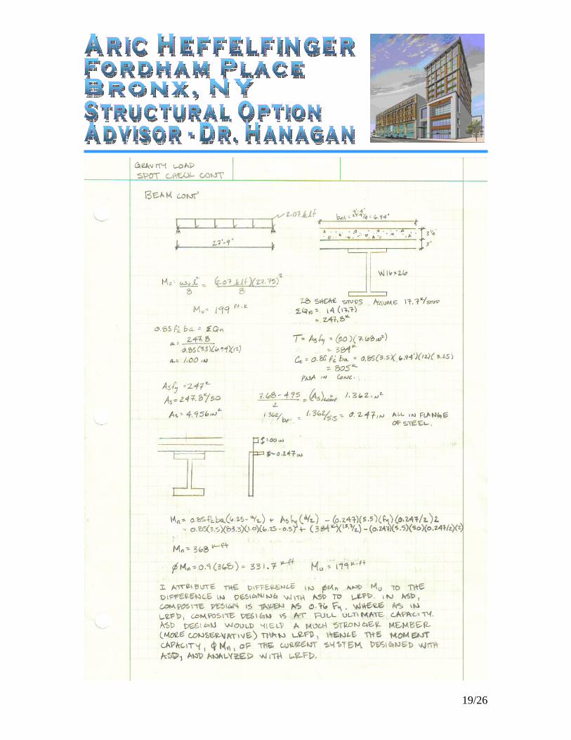
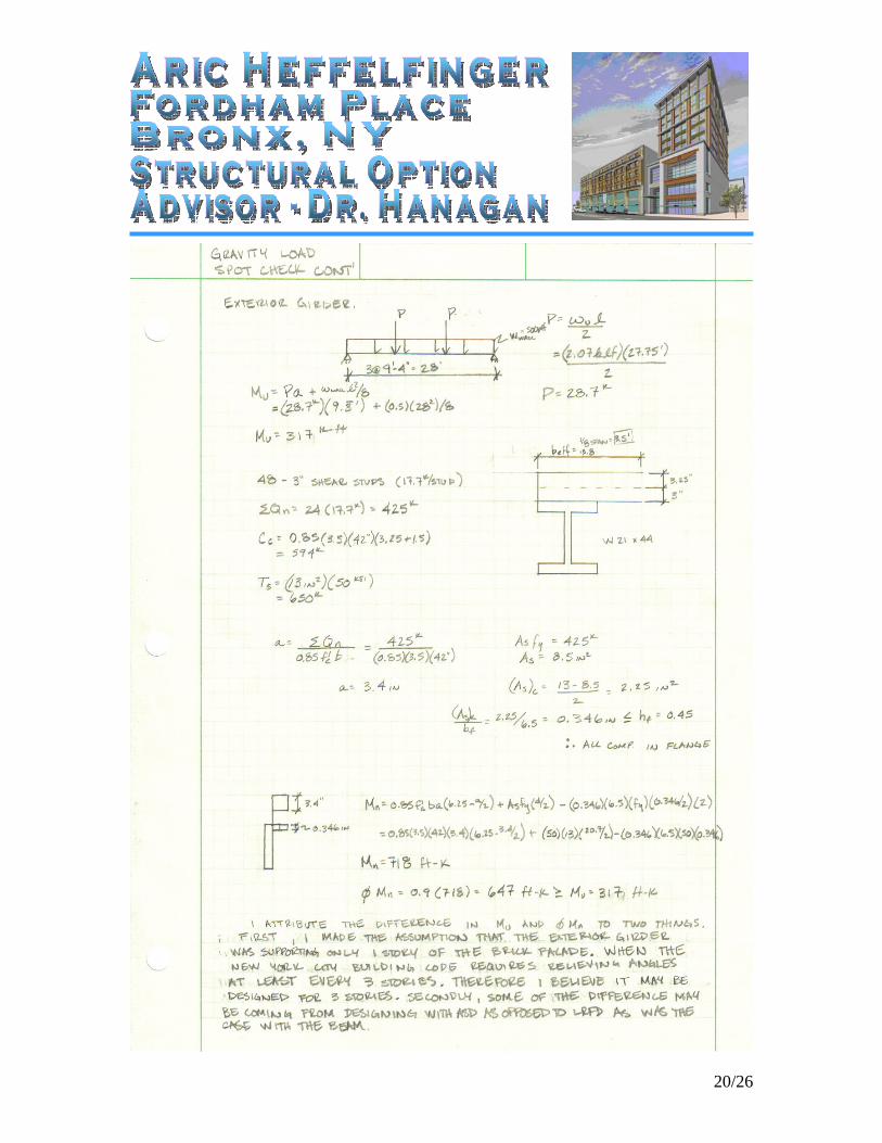
3.7 Gravity Load Spot Check
19/26
20/26
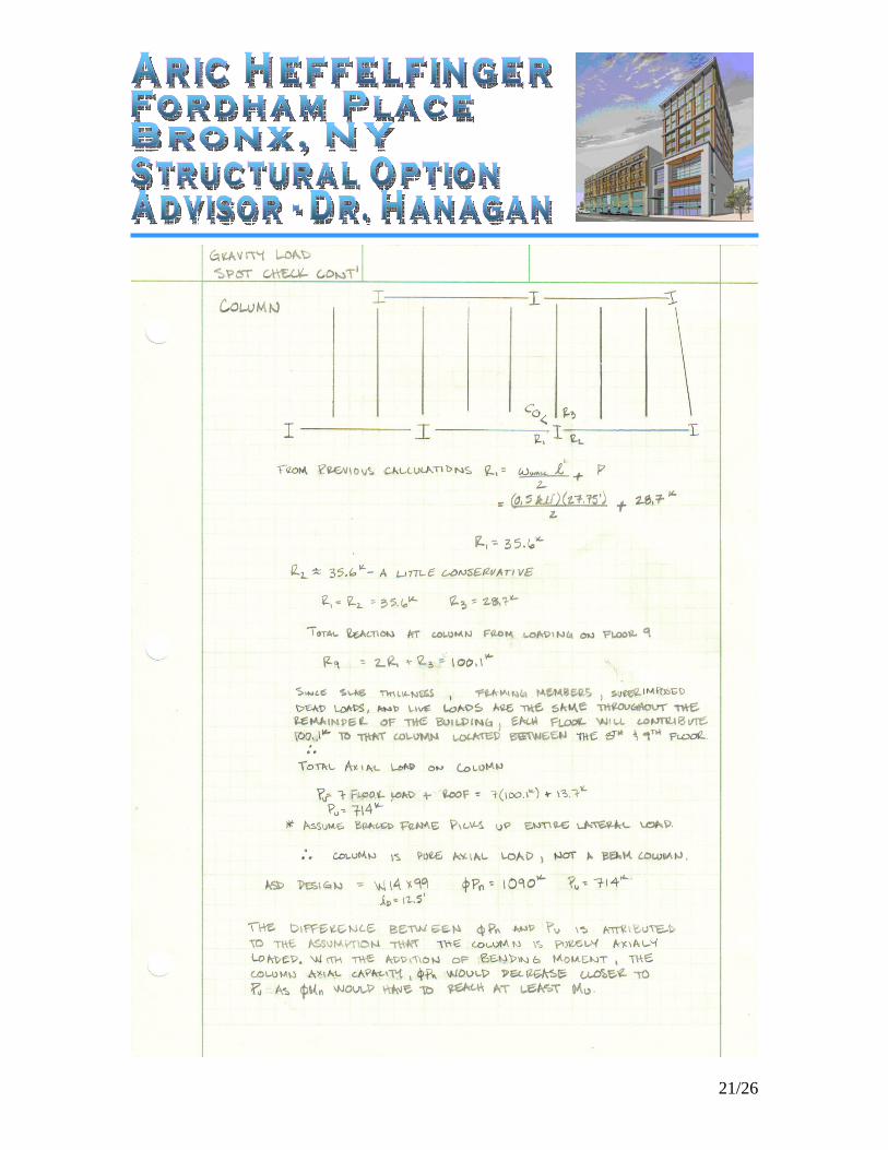
21/26

22/26
3.8 Lateral Load Spot Check
23/26
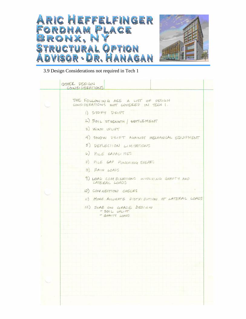
3.9 Design Considerations not required in Tech 1
24/26
4. Appendix
25/26
26/26