Embed Size (px)
Citation preview
IRC RB-236 ICC PUBLIC HEARING ::: September 2006
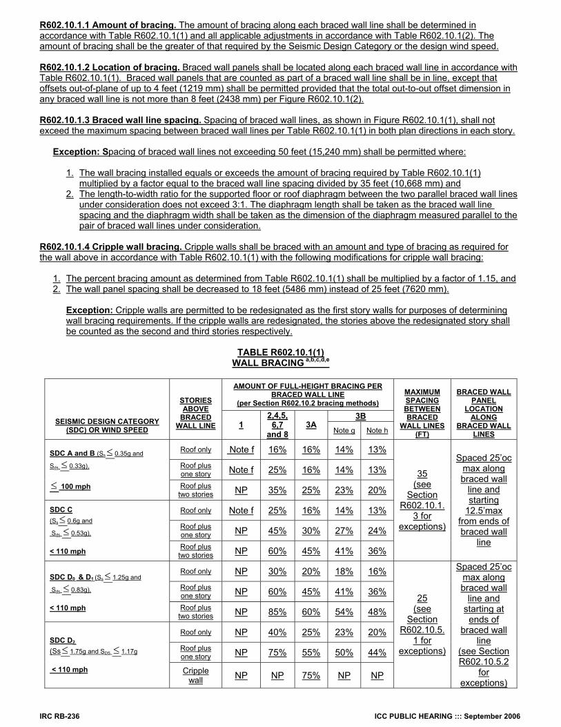
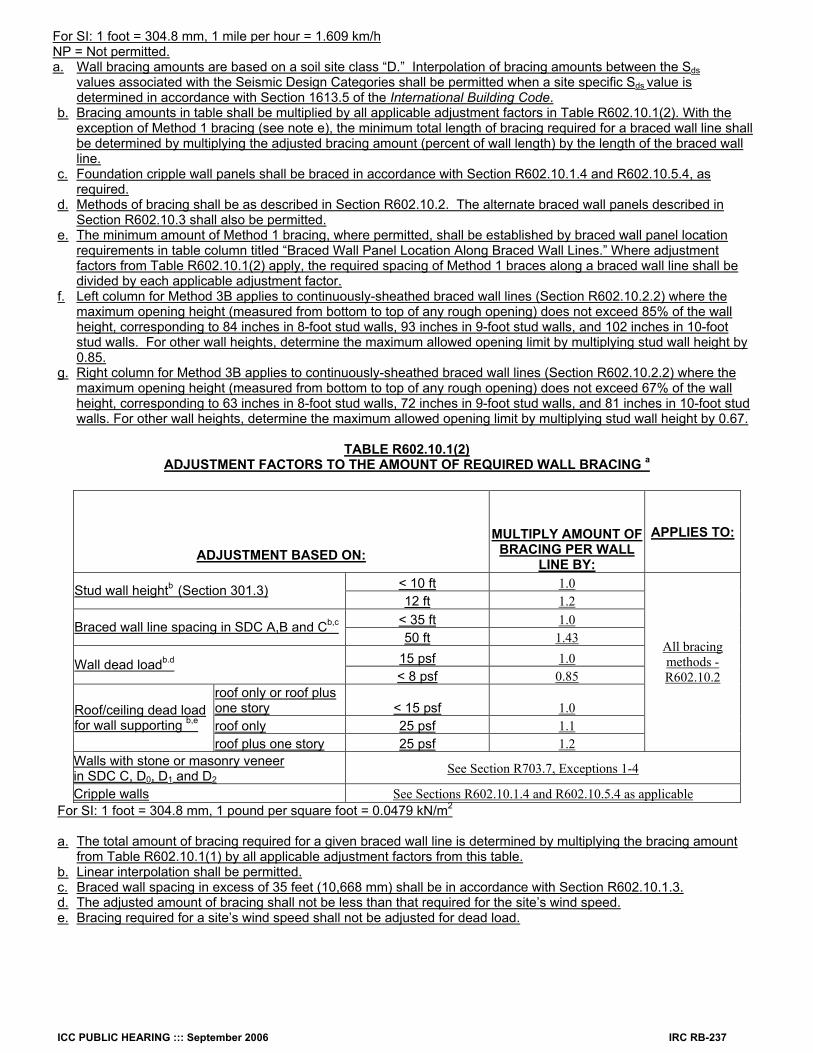
R602.10.1.1 Amount of bracing. The amount of bracing along each braced wall line shall be determined in accordance with Table R602.10.1(1) and all applicable adjustments in accordance with Table R602.10.1(2). The amount of bracing shall be the greater of that required by the Seismic Design Category or the design wind speed. R602.10.1.2 Location of bracing. Braced wall panels shall be located along each braced wall line in accordance with Table R602.10.1(1). Braced wall panels that are counted as part of a braced wall line shall be in line, except that offsets out-of-plane of up to 4 feet (1219 mm) shall be permitted provided that the total out-to-out offset dimension in any braced wall line is not more than 8 feet (2438 mm) per Figure R602.10.1(2). R602.10.1.3 Braced wall line spacing. Spacing of braced wall lines, as shown in Figure R602.10.1(1), shall not exceed the maximum spacing between braced wall lines per Table R602.10.1(1) in both plan directions in each story.
Exception: Spacing of braced wall lines not exceeding 50 feet (15,240 mm) shall be permitted where:
1. The wall bracing installed equals or exceeds the amount of bracing required by Table R602.10.1(1)
multiplied by a factor equal to the braced wall line spacing divided by 35 feet (10,668 mm) and 2. The length-to-width ratio for the supported floor or roof diaphragm between the two parallel braced wall lines
under consideration does not exceed 3:1. The diaphragm length shall be taken as the braced wall line spacing and the diaphragm width shall be taken as the dimension of the diaphragm measured parallel to the pair of braced wall lines under consideration.
R602.10.1.4 Cripple wall bracing. Cripple walls shall be braced with an amount and type of bracing as required for the wall above in accordance with Table R602.10.1(1) with the following modifications for cripple wall bracing:
1. The percent bracing amount as determined from Table R602.10.1(1) shall be multiplied by a factor of 1.15, and 2. The wall panel spacing shall be decreased to 18 feet (5486 mm) instead of 25 feet (7620 mm).
Exception: Cripple walls are permitted to be redesignated as the first story walls for purposes of determining wall bracing requirements. If the cripple walls are redesignated, the stories above the redesignated story shall be counted as the second and third stories respectively.
TABLE R602.10.1(1)
WALL BRACING a,b,c,d,e
AMOUNT OF FULL-HEIGHT BRACING PER BRACED WALL LINE
(per Section R602.10.2 bracing methods)
3B
SEISMIC DESIGN CATEGORY (SDC) OR WIND SPEED
STORIES ABOVE
BRACED WALL LINE 1
2,4,5,6,7
and 8 3A
Note g Note h
MAXIMUM SPACING BETWEEN BRACED
WALL LINES (FT)
BRACED WALL
PANEL LOCATION
ALONG BRACED WALL
LINES
Roof only Note f 16% 16% 14% 13%
Roof plus one story Note f 25% 16% 14% 13%
SDC A and B (Ss≤ 0.35g and
Sds ≤ 0.33g), ≤ 100 mph Roof plus
two stories NP 35% 25% 23% 20%
Roof only Note f 25% 16% 14% 13%
Roof plus one story NP 45% 30% 27% 24%
SDC C (Ss≤ 0.6g and
Sds ≤ 0.53g), < 110 mph Roof plus
two stories NP 60% 45% 41% 36%
35 (see
Section R602.10.1.
3 for exceptions)
Spaced 25’oc max along braced wall
line and starting
12.5’max from ends of braced wall
line
Roof only NP 30% 20% 18% 16%
Roof plus one story NP 60% 45% 41% 36%
SDC D0 & D1 (Ss≤ 1.25g and
Sds ≤ 0.83g), < 110 mph Roof plus
two stories NP 85% 60% 54% 48%
Roof only NP 40% 25% 23% 20%
Roof plus one story NP 75% 55% 50% 44%
SDC D2,
(Ss≤ 1.75g and SDS ≤ 1.17g < 110 mph Cripple
wall NP NP 75% NP NP
25 (see
Section R602.10.5.
1 for exceptions)
Spaced 25’oc max along braced wall
line and starting at
ends of braced wall
line (see Section R602.10.5.2
for exceptions)
ICC PUBLIC HEARING ::: September 2006 IRC RB-237
For SI: 1 foot = 304.8 mm, 1 mile per hour = 1.609 km/h NP = Not permitted. a. Wall bracing amounts are based on a soil site class “D.” Interpolation of bracing amounts between the Sds
values associated with the Seismic Design Categories shall be permitted when a site specific Sds value is determined in accordance with Section 1613.5 of the International Building Code.
b. Bracing amounts in table shall be multiplied by all applicable adjustment factors in Table R602.10.1(2). With the exception of Method 1 bracing (see note e), the minimum total length of bracing required for a braced wall line shall be determined by multiplying the adjusted bracing amount (percent of wall length) by the length of the braced wall line.
c. Foundation cripple wall panels shall be braced in accordance with Section R602.10.1.4 and R602.10.5.4, as required.
d. Methods of bracing shall be as described in Section R602.10.2. The alternate braced wall panels described in Section R602.10.3 shall also be permitted.
e. The minimum amount of Method 1 bracing, where permitted, shall be established by braced wall panel location requirements in table column titled “Braced Wall Panel Location Along Braced Wall Lines.” Where adjustment factors from Table R602.10.1(2) apply, the required spacing of Method 1 braces along a braced wall line shall be divided by each applicable adjustment factor.
f. Left column for Method 3B applies to continuously-sheathed braced wall lines (Section R602.10.2.2) where the maximum opening height (measured from bottom to top of any rough opening) does not exceed 85% of the wall height, corresponding to 84 inches in 8-foot stud walls, 93 inches in 9-foot stud walls, and 102 inches in 10-foot stud walls. For other wall heights, determine the maximum allowed opening limit by multiplying stud wall height by 0.85.
g. Right column for Method 3B applies to continuously-sheathed braced wall lines (Section R602.10.2.2) where the maximum opening height (measured from bottom to top of any rough opening) does not exceed 67% of the wall height, corresponding to 63 inches in 8-foot stud walls, 72 inches in 9-foot stud walls, and 81 inches in 10-foot stud walls. For other wall heights, determine the maximum allowed opening limit by multiplying stud wall height by 0.67.
TABLE R602.10.1(2)
ADJUSTMENT FACTORS TO THE AMOUNT OF REQUIRED WALL BRACING a
ADJUSTMENT BASED ON: MULTIPLY AMOUNT OF
BRACING PER WALL LINE BY:
APPLIES TO:
< 10 ft 1.0 Stud wall heightb (Section 301.3) 12 ft 1.2
< 35 ft 1.0 Braced wall line spacing in SDC A,B and Cb,c
50 ft 1.43 15 psf 1.0 Wall dead loadb.d < 8 psf 0.85
roof only or roof plus one story < 15 psf 1.0 roof only 25 psf 1.1
Roof/ceiling dead load for wall supporting b,e
roof plus one story 25 psf 1.2
All bracing methods - R602.10.2
Walls with stone or masonry veneer in SDC C, D0, D1 and D2
See Section R703.7, Exceptions 1-4
Cripple walls See Sections R602.10.1.4 and R602.10.5.4 as applicable For SI: 1 foot = 304.8 mm, 1 pound per square foot = 0.0479 kN/m2
a. The total amount of bracing required for a given braced wall line is determined by multiplying the bracing amount
from Table R602.10.1(1) by all applicable adjustment factors from this table. b. Linear interpolation shall be permitted. c. Braced wall spacing in excess of 35 feet (10,668 mm) shall be in accordance with Section R602.10.1.3. d. The adjusted amount of bracing shall not be less than that required for the site’s wind speed. e. Bracing required for a site’s wind speed shall not be adjusted for dead load.
IRC RB-238 ICC PUBLIC HEARING ::: September 2006
Pacific A 1
FIGURE R602.10.1 (1)
BRACED WALL PANELS AND BRACED WALL LINES
Pacific A 2
FIGURE R602.10.1(2)
OFFSETS PERMITTED FOR BRACED WALL LINES R602.10.2 Braced wall panel construction methods. The construction of braced wall panels shall be in accordance with one of the following methods:
1. Nominal 1-inch-by-4-inch (25.4 mm by 102 mm) continuous diagonal braces let in to the top and bottom plates and the intervening studs or approved metal strap devices installed in accordance with the manufacturer’s specifications. The let-in bracing shall be placed at an angle not more than 60 degrees (1.06 rad) or less than 45 degrees (0.79 rad) from the horizontal.
2. Wood boards of 5/8 inch (15.9 mm) net minimum thickness applied diagonally on studs spaced a maximum of 24 inches (610 mm). Diagonal boards shall be attached to studs in accordance with TableR602.3(1).
3A. Wood structural panel sheathing with a thickness not less than 5/16 inch (7.9mm)for 16-inch (406mm)stud spacing and not less than 3/8 inch (9.5mm)for 24-inch (610 mm) stud spacing. Wood structural panels shall be installed in accordance with Tables R602.3(1) and R602.3(3).
3B. Wood structural panels installed in accordance with Method 3A and applied to a continuously-sheathed braced wall line in accordance with Section R602.10.2.2.
4. One-half-inch (12.7 mm) or 25/32-inch (19.8 mm) thick structural fiberboard sheathing applied vertically or horizontally on studs spaced a maximum of 16 inches (406 mm) on center. Structural fiberboard sheathing shall be installed in accordance with Table R602.3(1).
5. Gypsum board with minimum 1/2-inch (12.7 mm) thickness placed on studs spaced a maximum of 24 inches (610 mm) on center and fastened at 7 inches (178 mm) on center with the size nails specified in TableR602.3(1) for sheathing and Table R702.3.5 for interior gypsum board.
6. Particleboard wall sheathing panels installed in accordance with Tables R602.3(1) and R602.3(4). 7. Portland cement plaster on studs spaced a maximum of 16 inches (406 mm) on center and installed in
accordance with Section R703.6. 8. Hardboard panel siding when installed in accordance with Table R703.4.
Exception: Alternate braced wall panels constructed in accordance with Section R602.10.3 shall be permitted to replace any of the above methods of braced wall panels, except Method 3B.
ICC PUBLIC HEARING ::: September 2006 IRC RB-239
R602.10.2.1 Length of braced panels. When counted toward the required total amount and location of bracing in a braced wall line per Section R602.10.1, the minimum length of individual braced wall panels constructed in accordance with Section R602.10.2 shall comply with Table R602.10.2(1).
Exceptions:
1. Lengths of braced wall panels for continuous wood structural panel sheathing shall be in accordance with Section R602.10.2.2.
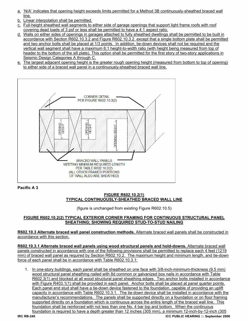
2. Lengths of alternate braced wall panels shall be in accordance with Section R602.10.3. R602.10.2.2 Continuous wood structural panel sheathing (Method 3B). When continuous wood structural panel sheathing, as shown in Figure R602.10.2(1) is provided in accordance with Method 3B of Section R602.10.2 on all sheathable areas of all exterior walls, and interior braced wall lines, where required, including areas above and below openings, braced wall panel lengths shall be in accordance with Table R602.10.2(2). Wood structural panel sheathing shall be installed at corners in accordance with Figure R602.10.2(2). R602.10.2.3 Panel joints. All vertical joints of panel sheathing shall occur over, and be fastened to, common studs. Horizontal joints in braced wall panels shall occur over, and be fastened to, common blocking of a minimum 1½ inch (38 mm) thickness.
Exception: Blocking is not required behind horizontal joints in Seismic Design Categories A and B and detached dwellings in Seismic Design Category C when constructed in accordance with Section R602.10.2, braced-wall-panel construction method 3A and Table R602.10.1(1), method 3A, or where permitted by the manufacturer’s installation requirements for the specific sheathing material.
R602.10.2.4 Connections. Braced wall line sole plates shall be fastened to the floor framing and top plates shall be connected to the framing above in accordance with Table R602.3(1). Sills shall be fastened to the foundation or slab in accordance with Section R403.1.6. Where joists are perpendicular to the braced wall lines above or below, blocking shall be provided between the joists and in line with the braced wall panels. Where joists are parallel to braced wall lines above or below, a rim joist or other parallel framing member shall be provided at the wall to permit fastening per Table R602.3(1).
TABLE R602.10.2(1) MINIMUM LENGTH REQUIREMENTS FOR BRACED WALL PANELS
HEIGHT OF BRACED WALL
PANEL BRACING METHOD 8 ft. 9 ft. 10 ft.
2,3A,4,5,6,7,8 and Method 5 when double sided 4’-0” 4’-0” 4’-0” Method 5, single sided 8’-0” 8’-0” 8’-0”
For SI: I inch = 25.4mm, 1 foot = 305 mm
TABLE R602.10.2(2)
MINIMUM LENGTH REQUIREMENTS FOR METHOD 3B BRACED WALL PANELS IN A CONTINUOUSLY-SHEATHED BRACED WALL LINEa,b,c, d
MINIMUM LENGTH (INCHES) LARGEST ADJACENT OPENING HEIGHTE (INCHES)
8-ft Wall 9-ft Wall 10-ft Wall102 N/A N/A 40 99 N/A N/A 38 96 N/A N/A 37 93 N/A 36 36 90 N/A 34 34 87 N/A 33 33 84 32 32 32 81 30 30 30 78 29 29 30 75 28 28 30 72 27 27 30 69 26 27 30 66 25 27 30 ≤63 24 27 30
For SI: 1 inch = 25.4 mm, 1 foot = 305 mm
IRC RB-240 ICC PUBLIC HEARING ::: September 2006
a. ‘N/A’ indicates that opening height exceeds limits permitted for a Method 3B continuously-sheathed braced wall line.
b. Linear interpolation shall be permitted. c. Full-height sheathed wall segments to either side of garage openings that support light frame roofs with roof
covering dead loads of 3 psf or less shall be permitted to have a 4:1 aspect ratio. d. Walls on either sides of openings in garages attached to fully sheathed dwellings shall be permitted to be built in
accordance with Section R602.10.3.2 and Figure R602.10.3.2 except that a single bottom plate shall be permitted and two anchor bolts shall be placed at 1/3 points. In addition, tie-down devices shall not be required and the vertical wall segment shall have a maximum 6:1 height-to-width ratio (with height being measured from top of header to the bottom of the sill plate). This option shall be permitted for the first story of two-story applications in Seismic Design Categories A through C.
e. The largest adjacent opening height is the greater rough opening height (measured from bottom to top of opening) to either side of a braced wall panel in a continuously-sheathed braced wall line.
Pacific A 3
FIGURE R602.10.2(1) TYPICAL CONTINUOUSLY-SHEATHED BRACED WALL LINE
(figure is unchanged from existing Figure R602.10.5)
FIGURE R602.10.2(2) TYPICAL EXTERIOR CORNER FRAMING FOR CONTINUOUS STRUCTURAL PANEL
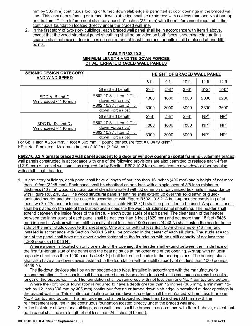
SHEATHING; SHOWING REQUIRED STUD-TO-STUD NAILING R602.10.3 Alternate braced wall panel construction methods. Alternate braced wall panels shall be constructed in accordance with this section. R602.10.3.1 Alternate braced wall panels using wood structural panels and hold-downs. Alternate braced wall panels constructed in accordance with one of the following provisions shall be permitted to replace each 4 feet (1219 mm) of braced wall panel as required by Section R602.10.2. The maximum height and minimum length, and tie-down force of each panel shall be in accordance with Table R602.10.3.1:
1. In one-story buildings, each panel shall be sheathed on one face with 3/8-inch-minimum-thickness (9.5 mm)
wood structural panel sheathing nailed with 8d common or galvanized box nails in accordance with Table R602.3(1) and blocked at all wood structural panel sheathing edges. Two anchor bolts installed in accordance with Figure R403.1(1) shall be provided in each panel. Anchor bolts shall be placed at panel quarter points. Each panel end stud shall have a tie-down device fastened to the foundation, capable of providing an uplift capacity in accordance with Table R602.10.3.1. The tie-down device shall be installed in accordance with the manufacturer’s recommendations. The panels shall be supported directly on a foundation or on floor framing supported directly on a foundation which is continuous across the entire length of the braced wall line. This foundation shall be reinforced with not less than one No. 4 bar top and bottom. When the continuous foundation is required to have a depth greater than 12 inches (305 mm), a minimum 12-inch-by-12-inch (305
ICC PUBLIC HEARING ::: September 2006 IRC RB-241
mm by 305 mm) continuous footing or turned down slab edge is permitted at door openings in the braced wall line. This continuous footing or turned down slab edge shall be reinforced with not less than one No.4 bar top and bottom. This reinforcement shall be lapped 15 inches (381 mm) with the reinforcement required in the continuous foundation located directly under the braced wall line.
2. In the first story of two-story buildings, each braced wall panel shall be in accordance with Item 1 above, except that the wood structural panel sheathing shall be provided on both faces, sheathing edge nailing spacing shall not exceed four inches on center, and at least three anchor bolts shall be placed at one-fifth points.
TABLE R602.10.3.1
MINIMUM LENGTH AND TIE-DOWN FORCES OF ALTERNATE BRACED WALL PANELS
HEIGHT OF BRACED WALL PANEL SEISMIC DESIGN CATEGORY
AND WIND SPEED
8 ft. 9 ft. 10 ft. 11 ft. 12 ft.
Sheathed Length 2’-4” 2’-8” 2’-8” 3’-2” 3’-6” R602.10.3.1, Item 1 Tie-
down Force (lbs) 1800 1800 1800 2000 2200 SDC A, B and C Wind speed < 110 mph
R602.10.3.1, Item 2 Tie-down Force (lbs) 3000 3000 3000 3300 3600
Sheathed Length 2’-8” 2’-8” 2’-8” NPa NPa R602.10.3.1, Item 1 Tie-
down Force (lbs) 1800 1800 1800 NPa NPa SDC Do, D1 and D2 Wind speed < 110 mph
R602.10.3.1, Item 2 Tie-down Force (lbs) 3000 3000 3000 NPa NPa
For SI: 1 inch = 25.4 mm, 1 foot = 305 mm, 1 pound per square foot = 0.0479 kN/m2
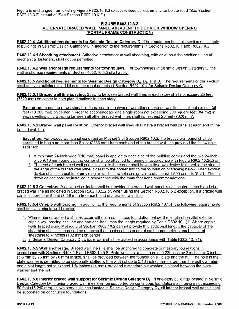
NP = Not Permitted. Maximum height of 10 feet (3,048 mm). R602.10.3.2 Alternate braced wall panel adjacent to a door or window opening (portal framing). Alternate braced wall panels constructed in accordance with one of the following provisions are also permitted to replace each 4 feet (1219 mm) of braced wall panel as required for by Section R602.10.2 for use adjacent to a window or door opening with a full-length header: 1. In one-story buildings, each panel shall have a length of not less than 16 inches (406 mm) and a height of not more
than 10 feet (3048 mm). Each panel shall be sheathed on one face with a single layer of 3/8-inch-minimum-thickness (10 mm) wood structural panel sheathing nailed with 8d common or galvanized box nails in accordance with Figure R602.10.3.2. The wood structural panel sheathing shall extend up over the solid sawn or glued-laminated header and shall be nailed in accordance with Figure R602.10.3.2. A built-up header consisting of at least two 2 x 12s and fastened in accordance with Table R602.3(1) shall be permitted to be used. A spacer, if used, shall be placed on the side of the built-up beam opposite the wood structural panel sheathing. The header shall extend between the inside faces of the first full-length outer studs of each panel. The clear span of the header between the inner studs of each panel shall be not less than 6 feet (1829 mm) and not more than 18 feet (5486 mm) in length. A strap with an uplift capacity of not less than 1000 pounds (4448 N) shall fasten the header to the side of the inner studs opposite the sheathing. One anchor bolt not less than 5/8-inch-diameter (16 mm) and installed in accordance with Section R403.1.6 shall be provided in the center of each sill plate. The studs at each end of the panel shall have a tie-down device fastened to the foundation with an uplift capacity of not less than 4,200 pounds (18 683 N).
Where a panel is located on only one side of the opening, the header shall extend between the inside face of the first full-length stud of the panel and the bearing studs at the other end of the opening. A strap with an uplift capacity of not less than 1000 pounds (4448 N) shall fasten the header to the bearing studs. The bearing studs shall also have a tie-down device fastened to the foundation with an uplift capacity of not less than 1000 pounds (4448 N).
The tie-down devices shall be an embedded-strap type, installed in accordance with the manufacturer’s recommendations. The panels shall be supported directly on a foundation which is continuous across the entire length of the braced wall line. The foundation shall be reinforced with not less than one No. 4 bar top and bottom.
Where the continuous foundation is required to have a depth greater than 12 inches (305 mm), a minimum 12-inch-by-12-inch (305 mm by 305 mm) continuous footing or turned down slab edge is permitted at door openings in the braced wall line. This continuous footing or turned down slab edge shall be reinforced with not less than one No. 4 bar top and bottom. This reinforcement shall be lapped not less than 15 inches (381 mm) with the reinforcement required in the continuous foundation located directly under the braced wall line.
2. In the first story of two-story buildings, each wall panel shall be braced in accordance with Item 1 above, except that each panel shall have a length of not less than 24 inches (610 mm).
IRC RB-242 ICC PUBLIC HEARING ::: September 2006
Figure is unchanged from existing Figure R602.10.6.2 except revised callout on anchor bolt to read “See Section R602.10.3.2”instead of “See Section R602.10.6.2”)
FIGURE R602.10.3.2
ALTERNATE BRACED WALL PANEL ADJACENT TO DOOR OR WINDOW OPENING (PORTAL FRAME CONSTRUCTION)
R602.10.4 Additional requirements for Seismic Design Category C. The requirements of this section shall apply to buildings in Seismic Design Category C in addition to the requirements in Sections R602.10.1 and R602.10.2. R602.10.4.1 Sheathing attachment. Adhesive attachment of wall sheathing, with or without the additional use of mechanical fasteners, shall not be permitted.
R602.10.4.2 Wall anchorage requirements for townhouses. For townhouses in Seismic Design Category C, the wall anchorage requirements of Section R602.10.5.5 shall apply. R602.10.5 Additional requirements for Seismic Design Category D0, D1, and D2. The requirements of this section shall apply to buildings in addition to the requirements of Section R602.10.4 for Seismic Design Category C. R602.10.5.1 Braced wall line spacing. Spacing between braced wall lines in each story shall not exceed 25 feet (7620 mm) on center in both plan directions in each story.
Exception: In one- and two-story buildings, spacing between two adjacent braced wall lines shall not exceed 35 feet (10 363 mm) on center in order to accommodate one single room not exceeding 900 square feet (84 m2) in each dwelling unit. Spacing between all other braced wall lines shall not exceed 25 feet (7620 mm).
R602.10.5.2 Braced wall panel location. Exterior braced wall lines shall have a braced wall panel at each end of the braced wall line.
Exception: For braced wall panel construction Method 3 of Section R602.10.2, the braced wall panel shall be permitted to begin no more than 8 feet (2438 mm) from each end of the braced wall line provided the following is satisfied:
1. A minimum 24-inch-wide (610 mm) panel is applied to each side of the building corner and the two 24-inch- wide (610 mm) panels at the corner shall be attached to framing in accordance with Figure R602.10.2(2) or, 2. The end of each braced wall panel closest to the corner shall have a tie-down device fastened to the stud at the edge of the braced wall panel closest to the corner and to the foundation or framing below. The tie-down device shall be capable of providing an uplift allowable design value of at least 1,800 pounds (8 kN). The tie- down device shall be installed in accordance with the manufacturer’s recommendations.
R602.10.5.3 Collectors. A designed collector shall be provided if a braced wall panel is not located at each end of a braced wall line as indicated in Section R602.10.5.2 or, when using the Section R602.10.5.2 exception, if a braced wall panel is more than 8 feet (2438 mm) from each end of a braced wall line. R602.10.5.4 Cripple wall bracing. In addition to the requirements of Section R602.10.1.4, the following requirements shall apply to cripple wall bracing:
1. Where interior braced wall lines occur without a continuous foundation below, the length of parallel exterior cripple wall bracing shall be one and one-half times the length required by Table R602.10.1(1).Where cripple walls braced using Method 3 of Section R602.10.2 cannot provide this additional length, the capacity of the sheathing shall be increased by reducing the spacing of fasteners along the perimeter of each piece of sheathing to 4 inches (102 mm) on center. 2. In Seismic Design Category D2, cripple walls shall be braced in accordance with Table R602.10.1(1).
R602.10.5.5 Wall anchorage. Braced wall line sills shall be anchored to concrete or masonry foundations in accordance with Sections R403.1.6 and R602.10.5.8. Plate washers, a minimum of 0.229 inch by 3 inches by 3 inches (5.8 mm by 76 mm by 76 mm) in size, shall be provided between the foundation sill plate and the nut. The hole in the plate washer is permitted to be diagonally slotted with a width of up to 3/16 inch (5 mm) larger than the bolt diameter and a slot length not to exceed 1 ¾ inches (44 mm), provided a standard cut washer is placed between the plate washer and the nut. R602.10.5.6 Interior braced wall support for Seismic Design Category D2. In one-story buildings located in Seismic Design Category D2, interior braced wall lines shall be supported on continuous foundations at intervals not exceeding 50 feet (15 240 mm). In two story buildings located in Seismic Design Category D2, all interior braced wall panels shall be supported on continuous foundations.
ICC PUBLIC HEARING ::: September 2006 IRC RB-243
Exception: Two-story buildings shall be permitted to have interior braced wall lines supported on continuous foundations at intervals not exceeding 50 feet (15 240 mm) provided that:
1. The height of cripple walls does not exceed 4 feet (1219 mm). 2. First-floor braced wall panels are supported on doubled floor joists, continuous blocking or floor beams. 3. The distance between bracing lines does not exceed twice the building width measured parallel to the braced wall line.
R602.10.5.7 Interior braced wall panel connections. Interior braced wall lines shall be fastened to floor and roof framing in accordance with Table R602.3(1), to required foundations in accordance with Section R602.10.5.5, and in accordance with the following requirements:
1. Floor joists parallel to the top plate shall be toe-nailed to the top plate with at least 8d nails spaced a maximum
of 6 inches (150 mm) on center. 2. Top plate laps shall be face-nailed with at least eight 16d nails on each side of the splice.
R602.10.5.8 Stepped foundations. Where stepped foundations occur, the following requirements apply:
1. Where the height of a required braced wall panel that extends from foundation to floor above varies more than 4 feet (1220 mm), the braced wall panel shall be constructed in accordance with Figure R602.10.5.8. 2. Where the lowest floor framing rests directly on a sill bolted to a foundation not less than 8 feet (2440 mm) in length along a line of bracing, the line shall be considered as braced. The double plate of the cripple stud wall beyond the segment of footing that extends to the lowest framed floor shall be spliced by extending the upper top plate a minimum of 4 feet (1219 mm) along the foundation. Anchor bolts shall be located a maximum of 1 foot and 3 feet (305 and 914 mm) from the step in the foundation. 3. Where cripple walls occur between the top of the foundation and the lowest floor framing, the bracing requirements for a story shall apply. 4. Where only the bottom of the foundation is stepped and the lowest floor framing rests directly on a sill bolted to the foundations, the requirements of Section R602.10.5.5 shall apply.
FIGURE R602.10.5.8
STEPPED FOUNDATION CONSTRUCTION (No change from existing Figure R602.11.3) Reason: To improve the organization, usability, and clarity of IRC wall bracing provisions. There are four main features of this editorial (non-technical) proposal to improve the usability of the wall bracing provisions and related requirements:
1. The organization of Sections R602.10 and R602.11 has been streamlined (see outline below) and condensed for improved readability, clarity, and flow of logic.
2. Bracing amounts and key requirements for all methods (including continuous structural panel sheathing) have been consolidated into the bracing amount table. This creates a visual picture of the key bracing requirements in the code and reduces some of the calculation involved in determining bracing amounts. In addition, bracing adjustment factors scattered throughout the code have been gathered into a single table such that inadvertent errors and omissions are prevented. Finally, matters pertaining to braced wall panel construction methods have been grouped under a single heading.
3. Illustrations have been included where necessary to improve understanding of the code text. 4. The additional requirements related to higher Seismic Design Categories have been more clearly organized to prevent inadvertent omission
or confusion by those in high seismic hazard areas. It also has been organized to o avoid cluttering of the code language with special requirements that don’t apply to the majority of code users in low-hazard areas of the country.
The outline of the proposed re-organization of Sections R602.10 and R602.11 is as follows: R602.10 Wall Bracing
R602.10.1 Braced wall lines
R602.10.1.1 Amount of bracing R602.10.1.2 Location of bracing R602.10.1.3 Braced wall line spacing R602.10.1.4 Cripple wall bracing
R602.10.2 Braced wall panel construction methods R602.10.2.1 Length of braced panels R602.10.2.2 Continuous wood structural panel sheathing (Method 3B) R602.10.2.3 Panel joints R602.10.2.4 Connections
R602.10.3 Alternate braced wall panels
R602.10.3.1 Alternate braced wall panels using wood structural panels and hold-downs R602.10.3.2 Alternate braced wall panel adjacent to a door or window opening (portal framing)
R602.10.4 Additional requirements for Seismic Design Category C
R602.10.4.1 Sheathing attachment R602.10.4.2 Wall anchorage requirements for townhouses
IRC RB-244 ICC PUBLIC HEARING ::: September 2006
R602.10.5 Additional requirements for Seismic Design Categories D0, D1, and D2
R602.10.5.1 Braced wall line spacing R602.10.5.2 Braced wall panel location R602.10.5.3 Collectors R602.10.5.4 Cripple wall bracing R602.10.5.5 Wall anchorage R602.10.5.6 Interior braced wall support for Seismic Design Category D2 R602.10.5.7 Interior braced wall panel connections R602.10.5.8 Stepped foundations
This proposal has received substantial input from a number of code officials and other code users including producers, designers, and suppliers
who are daily users of the code. It is hoped that, in view of other similar proposals, the unique and beneficial solutions in this proposal are carefully considered in an effort to editorially improve the wall bracing provisions in the IRC. For the reasons stated above, it is felt that this proposal represents a near optimal arrangement and clarification of existing wall bracing provisions in the IRC from the perspective of varied use conditions and end-users across the U.S. Cost Impact: The code change proposal will not increase the cost of construction. Public Hearing: Committee: AS AM D Assembly: ASF AMF DF
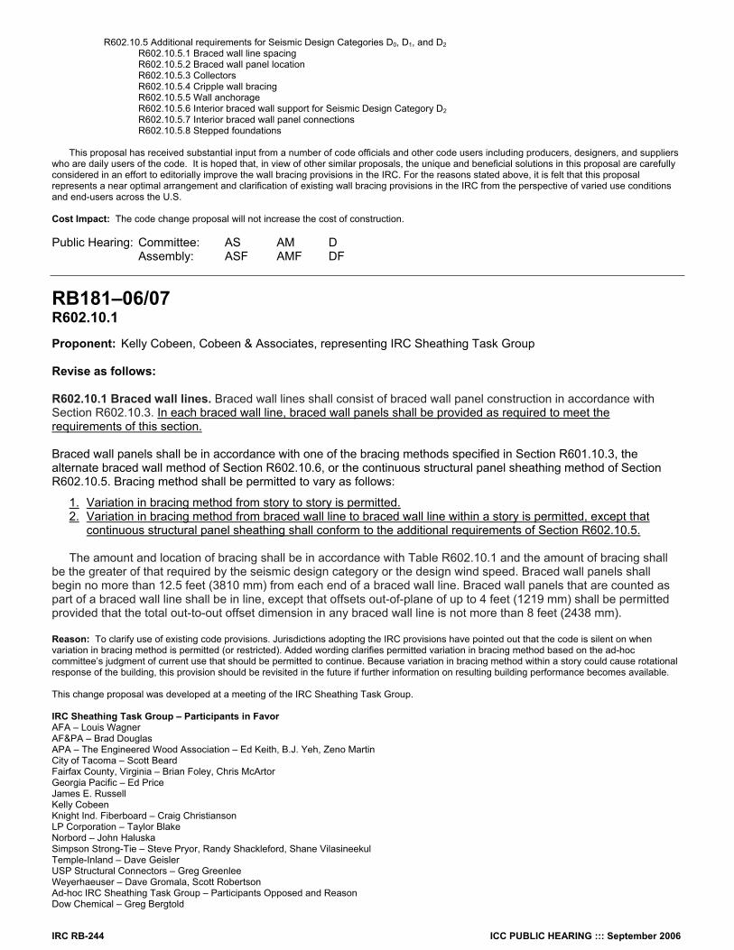
RB181–06/07 R602.10.1 Proponent: Kelly Cobeen, Cobeen & Associates, representing IRC Sheathing Task Group Revise as follows: R602.10.1 Braced wall lines. Braced wall lines shall consist of braced wall panel construction in accordance with Section R602.10.3. In each braced wall line, braced wall panels shall be provided as required to meet the requirements of this section. Braced wall panels shall be in accordance with one of the bracing methods specified in Section R601.10.3, the alternate braced wall method of Section R602.10.6, or the continuous structural panel sheathing method of Section R602.10.5. Bracing method shall be permitted to vary as follows:
1. Variation in bracing method from story to story is permitted. 2. Variation in bracing method from braced wall line to braced wall line within a story is permitted, except that continuous structural panel sheathing shall conform to the additional requirements of Section R602.10.5.
The amount and location of bracing shall be in accordance with Table R602.10.1 and the amount of bracing shall
be the greater of that required by the seismic design category or the design wind speed. Braced wall panels shall begin no more than 12.5 feet (3810 mm) from each end of a braced wall line. Braced wall panels that are counted as part of a braced wall line shall be in line, except that offsets out-of-plane of up to 4 feet (1219 mm) shall be permitted provided that the total out-to-out offset dimension in any braced wall line is not more than 8 feet (2438 mm). Reason: To clarify use of existing code provisions. Jurisdictions adopting the IRC provisions have pointed out that the code is silent on when variation in bracing method is permitted (or restricted). Added wording clarifies permitted variation in bracing method based on the ad-hoc committee’s judgment of current use that should be permitted to continue. Because variation in bracing method within a story could cause rotational response of the building, this provision should be revisited in the future if further information on resulting building performance becomes available. This change proposal was developed at a meeting of the IRC Sheathing Task Group. IRC Sheathing Task Group – Participants in Favor AFA – Louis Wagner AF&PA – Brad Douglas APA – The Engineered Wood Association – Ed Keith, B.J. Yeh, Zeno Martin City of Tacoma – Scott Beard Fairfax County, Virginia – Brian Foley, Chris McArtor Georgia Pacific – Ed Price James E. Russell Kelly Cobeen Knight Ind. Fiberboard – Craig Christianson LP Corporation – Taylor Blake Norbord – John Haluska Simpson Strong-Tie – Steve Pryor, Randy Shackleford, Shane Vilasineekul Temple-Inland – Dave Geisler USP Structural Connectors – Greg Greenlee Weyerhaeuser – Dave Gromala, Scott Robertson Ad-hoc IRC Sheathing Task Group – Participants Opposed and Reason Dow Chemical – Greg Bergtold
ICC PUBLIC HEARING ::: September 2006 IRC RB-245
Reason: The removal of #3 mixed wall bracing in a given wall line has changed the scope of this proposal in my estimation now restricting its use. In applications where interior and exterior braced lines are the same, utilizing drywall in conjunction with other bracing methods in the same wall for the exterior areas has been practiced for many years successfully, or for other reasons not noted, mixed bracing methods are currently used where applicable. This proposal appears to be technical change which serves to eliminate this practice. Covalence Coated Products – Brad Allshouse Reason: This proposal is not a clarification, but is a technical change. In the code’s current silence and in current practice, different bracing methods are used on a given braced wall line for some applications. No evidence has been submitted to suggest that this allowance and practice has caused problems and in what circumstances. This proposal restricts a current practice that is allowed by the code and is therefore technical in nature and should have a technical and practical/experience basis for the change. Of equal importance, this proposal does not deal consistently with the mixed bracing issue for all affected bracing methods. Covalence Coated Products – Edward Chan Reason: It is a reinterpretation of the Code; hence it is a technical change. Mixing of brace methods within a wall line is omitted on this proposal but is silent in Code. NAHB Research Center/ NAHB – Vladimir Kochkin, Ed Sutton Reason: This is a significant technical change, not a clarification. This proposal introduces a permissive language for combining some systems, but is silent on others (i.e., combination in a braced wall line). This will be interpreted that combining methods in the same braced wall line is not permitted. The proposed language will restrict systems that are currently used in practice. This change should not be done without technical substantiation. I will change my position to in Favor if a third item is added to the list as follows: 3. Variation in bracing method within a braced wall line is permitted, except that continuous structural panel sheathing shall conform to the additional requirements of Section R602.10.5. PIMA / API– Lorraine Ross WTCA – Will Warlick Reason: See Brad Allshouse reason. XPSA – Susan Herrenbruck Reason: See Brad Allshouse and Greg Bergtold reasons. Cost Impact: The code change proposal will not increase the cost of construction. Public Hearing: Committee: AS AM D Assembly: ASF AMF DF
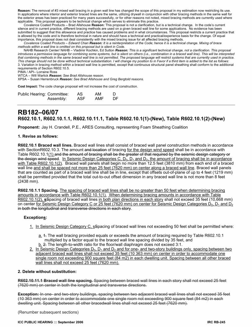
RB182–06/07 R602.10.1, R602.10.1.1, R602.10.11.1, Table R602.10.1(1)-(New), Table R602.10.1(2)-(New) Proponent: Jay H. Crandell, P.E., ARES Consulting, representing Foam Sheathing Coalition 1. Revise as follows: R602.10.1 Braced wall lines. Braced wall lines shall consist of braced wall panel construction methods in accordance with SectionR602.10.3. The amount and location of bracing for the design wind speed shall be in accordance with Table R602.10.1(1) and the amount of bracing shall be the greater of that required by the seismic design category or the design wind speed. In Seismic Design Categories C, D0, D1 and D2, the amount of bracing shall be in accordance with Table R602.10.1(2). Braced wall panels shall begin no more than 12.5 feet (3810 mm) from each end of a braced wall line and shall be spaced not more than 25 feet (7620 mm) on center along a braced wall line. Braced wall panels that are counted as part of a braced wall line shall be in line, except that offsets out-of-plane of up to 4 feet (1219 mm) shall be permitted provided that the total out-to-out offset dimension in any braced wall line is not more than 8 feet (2438 mm). R602.10.1.1 Spacing. The spacing of braced wall lines shall be no greater than 50 feet when determining bracing amounts in accordance with Table R602.10.1(1). When determining bracing amounts in accordance with Table R602.10.1(2), sSpacing of braced wall lines in both plan directions in each story shall not exceed 35 feet (10,668 mm) on center for Seismic Design Category C or 25 feet (7620 mm) on center for Seismic Design Categories D0, D1 and D2 in both the longitudinal and transverse directions in each story.
Exceptions:
1. In Seismic Design Category C, sSpacing of braced wall lines not exceeding 50 feet shall be permitted where:
a. 1. The wall bracing provided equals or exceeds the amount of bracing required by Table R602.10.1 multiplied by a factor equal to the braced wall line spacing divided by 35 feet, and
b. 2. The length-to-width ratio for the floor/wall diaphragm does not exceed 3:1. 2. In Seismic Design Categories D0, D1 and D2 and for one- and two-story buildings only, spacing between two adjacent braced wall lines shall not exceed 35 feet (10 363 mm) on center in order to accommodate one single room not exceeding 900 square feet (84 m2) in each dwelling unit. Spacing between all other braced wall lines shall not exceed 25 feet (7620 mm).
2. Delete without substitution: R602.10.11.1 Braced wall line spacing. Spacing between braced wall lines in each story shall not exceed 25 feet (7620 mm) on center in both the longitudinal and transverse directions. Exception: In one- and two-story buildings, spacing between two adjacent braced wall lines shall not exceed 35 feet (10 363 mm) on center in order to accommodate one single room not exceeding 900 square feet (84 m2) in each dwelling unit. Spacing between all other bracedwall lines shall not exceed 25 feet (7620 mm). (Renumber subsequent sections)
IRC RB-246 ICC PUBLIC HEARING ::: September 2006
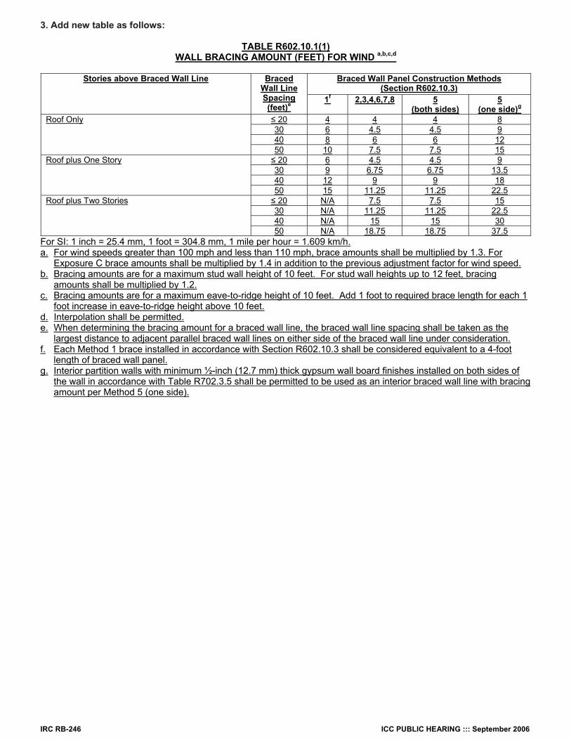
3. Add new table as follows:
TABLE R602.10.1(1) WALL BRACING AMOUNT (FEET) FOR WIND a,b,c,d
Braced Wall Panel Construction Methods
(Section R602.10.3) Stories above Braced Wall Line Braced
Wall Line Spacing (feet)e
1f 2,3,4,6,7,8 5 (both sides)
5 (one side)g
≤ 20 4 4 4 8 30 6 4.5 4.5 9 40 8 6 6 12
Roof Only
50 10 7.5 7.5 15 ≤ 20 6 4.5 4.5 9 30 9 6.75 6.75 13.5 40 12 9 9 18
Roof plus One Story
50 15 11.25 11.25 22.5 ≤ 20 N/A 7.5 7.5 15 30 N/A 11.25 11.25 22.5 40 N/A 15 15 30
Roof plus Two Stories
50 N/A 18.75 18.75 37.5 For SI: 1 inch = 25.4 mm, 1 foot = 304.8 mm, 1 mile per hour = 1.609 km/h. a. For wind speeds greater than 100 mph and less than 110 mph, brace amounts shall be multiplied by 1.3. For
Exposure C brace amounts shall be multiplied by 1.4 in addition to the previous adjustment factor for wind speed. b. Bracing amounts are for a maximum stud wall height of 10 feet. For stud wall heights up to 12 feet, bracing
amounts shall be multiplied by 1.2. c. Bracing amounts are for a maximum eave-to-ridge height of 10 feet. Add 1 foot to required brace length for each 1
foot increase in eave-to-ridge height above 10 feet. d. Interpolation shall be permitted. e. When determining the bracing amount for a braced wall line, the braced wall line spacing shall be taken as the
largest distance to adjacent parallel braced wall lines on either side of the braced wall line under consideration. f. Each Method 1 brace installed in accordance with Section R602.10.3 shall be considered equivalent to a 4-foot
length of braced wall panel. g. Interior partition walls with minimum ½-inch (12.7 mm) thick gypsum wall board finishes installed on both sides of
the wall in accordance with Table R702.3.5 shall be permitted to be used as an interior braced wall line with bracing amount per Method 5 (one side).
ICC PUBLIC HEARING ::: September 2006 IRC RB-247
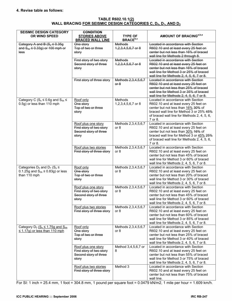
4. Revise table as follows:
TABLE R602.10.1(2) WALL BRACING FOR SEISMIC DESIGN CATEGORIES C, D0, D1, AND D2
SEISMIC DESIGN CATEGORY
OR WIND SPEED CONDITION
STORIES ABOVE BRACED WALL LINE
TYPE OF BRACEb,c
AMOUNT OF BRACINGa,b,e
One story Top of two or three story
Methods 1,2,3,4,5,6,7 or 8
Located in accordance with Section R602.10 and at least every 25 feet on center but not less than 16% of braced wall line for Methods 2 through 8.
First story of two story Second story of three story
Methods 1,2,3,4,5,6,7 or 8
Located in accordance with Section R602.10 and at least every 25 feet on center but not less than 16% of braced wall line for Method 3 or 25% of braced wall line for Methods 2, 4, 5, 6, 7 or 8.
Category A and B (Ss ≤ 0.35g and Sds ≤ 0.33g) or 100 mph or less
First story of three story Methods 2,3,4,5,6,7 or 8
Located in accordance with Section R602.10 and at least every 25 feet on center but not less than 25% of braced wall line for Method 3 or 35% of braced wall line for Methods 2, 4, 5, 6, 7 or 8.
Roof only One story Top of two or three story
Methods 1,2,3,4,5,6,7 or 8
Located in accordance with Section R602.10 and at least every 25 feet on center but not less than 16% 30% of braced wall line for Method 3 or 25% 45% of braced wall line for Methods 2, 4, 5, 6, 7 or 8.
Roof plus one story First story of two story Second story of three story
Methods 2,3,4,5,6,7 or 8
Located in accordance with Section R602.10 and at least every 25 feet on center but not less than 30% 16% of braced wall line for Method 3 or 45% 25% of braced wall line for Methods 2, 4, 5, 6, 7 or 8.
Category C (Ss ≤ 0.6g and Sds ≤ 0.5g) or less than 110 mph
Roof plus two stories First story of three story
Methods 2,3,4,5,6,7 or 8
Located in accordance with Section R602.10 and at least every 25 feet on center but not less than 45% of braced wall line for Method 3 or 60% of braced wall line for Methods 2, 4, 5, 6, 7 or 8.
Roof only One story Top of two or three story
Methods 2,3,4,5,6,7 or 8
Located in accordance with Section R602.10 and at least every 25 feet on center but not less than 20% of braced wall line for Method 3 or 30% of braced wall line for Methods 2, 4, 5, 6, 7 or 8.
Roof plus one story First story of two story Second story of three story
Methods 2,3,4,5,6,7 or 8
Located in accordance with Section R602.10 and at least every 25 feet on center but not less than 45% of braced wall line for Method 3 or 60% of braced wall line for Methods 2, 4, 5, 6, 7 or 8.
Categories D0 and D1 (Ss ≤ 0.1.25g and Sds ≤ 0.83g) or less than 110 mph
Roof plus two stories First story of three story
Methods 2,3,4,5,6,7 or 8
Located in accordance with Section R602.10 and at least every 25 feet on center but not less than 60% of braced wall line for Method 3 or 85% of braced wall line for Methods 2, 4, 5, 6, 7 or 8.
Roof only One story Top of two or three story
Methods 2,3,4,5,6,7 or 8
Located in accordance with Section R602.10 and at least every 25 feet on center but not less than 25% of braced wall line for Method 3 or 40% of braced wall line for Methods 2, 4, 5, 6, 7 or 8.
Roof plus one story First story of two story Second story of three story
Method 3,4,5,6,7 or 8
Located in accordance with Section R602.10 and at least every 25 feet on center but not less than 55% of braced wall line for Method 3 or 75% of braced wall line for Methods 2, 4, 5, 6, 7 or 8.
Category D2 (Ss ≤ 1.75g and Sds ≤ 1.17g) or less than 110 mph
Roof plus two stories First story of three story
Method 3 Located in accordance with Section R602.10 and at least every 25 feet on center but not less than 75% of braced wall line.
For SI: 1 inch = 25.4 mm, 1 foot = 304.8 mm, 1 pound per square foot = 0.0479 kN/m2, 1 mile per hour = 1.609 km/h.
IRC RB-248 ICC PUBLIC HEARING ::: September 2006
a. Wall bracing amounts are based on a soil site class “D”. Interpolation of bracing amounts between the Sds values associated with the Seismic Design Categories shall be permitted when a site specific Sds value is determined in accordance with Section 1613.5 of the International Building Code.
b. Foundation cripple wall panels shall be braced in accordance with Section R602.10.2. c. Methods of bracing shall be as described in Section R602.10.3. The alternate braced wall panels described in
Section R602.10.6.1 or R602.10.6.2 shall also be permitted. d. The bracing amounts for Seismic Design Categories are based on a 15 psf wall dead load. For walls with a dead
load of 8 psf or less, the bracing amounts shall be permitted to be multiplied by 0.85 provided that the adjusted bracing amount is not less than that required for the site’s wind speed. The minimum length of braced panel shall not be less than required by Section R602.10.3.
e. When the dead load of the roof/ceiling exceeds 15 psf, the bracing amounts shall be increased in accordance with Section R301.2.2.4. Bracing required for a site’s wind speed shall not be adjusted.
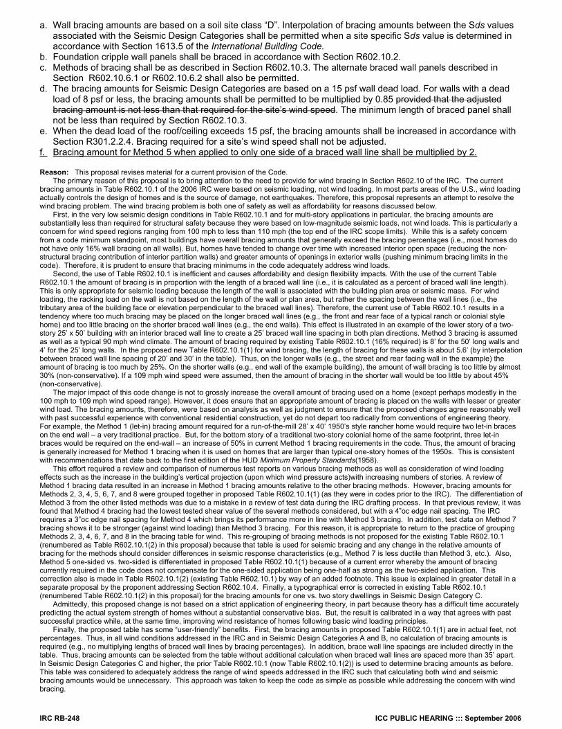
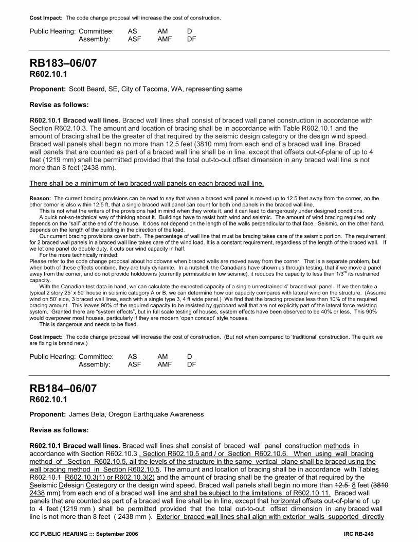
f. Bracing amount for Method 5 when applied to only one side of a braced wall line shall be multiplied by 2. Reason: This proposal revises material for a current provision of the Code. The primary reason of this proposal is to bring attention to the need to provide for wind bracing in Section R602.10 of the IRC. The current bracing amounts in Table R602.10.1 of the 2006 IRC were based on seismic loading, not wind loading. In most parts areas of the U.S., wind loading actually controls the design of homes and is the source of damage, not earthquakes. Therefore, this proposal represents an attempt to resolve the wind bracing problem. The wind bracing problem is both one of safety as well as affordability for reasons discussed below. First, in the very low seismic design conditions in Table R602.10.1 and for multi-story applications in particular, the bracing amounts are substantially less than required for structural safety because they were based on low-magnitude seismic loads, not wind loads. This is particularly a concern for wind speed regions ranging from 100 mph to less than 110 mph (the top end of the IRC scope limits). While this is a safety concern from a code minimum standpoint, most buildings have overall bracing amounts that generally exceed the bracing percentages (i.e., most homes do not have only 16% wall bracing on all walls). But, homes have tended to change over time with increased interior open space (reducing the non-structural bracing contribution of interior partition walls) and greater amounts of openings in exterior walls (pushing minimum bracing limits in the code). Therefore, it is prudent to ensure that bracing minimums in the code adequately address wind loads. Second, the use of Table R602.10.1 is inefficient and causes affordability and design flexibility impacts. With the use of the current Table R602.10.1 the amount of bracing is in proportion with the length of a braced wall line (i.e., it is calculated as a percent of braced wall line length). This is only appropriate for seismic loading because the length of the wall is associated with the building plan area or seismic mass. For wind loading, the racking load on the wall is not based on the length of the wall or plan area, but rather the spacing between the wall lines (i.e., the tributary area of the building face or elevation perpendicular to the braced wall lines). Therefore, the current use of Table R602.10.1 results in a tendency where too much bracing may be placed on the longer braced wall lines (e.g., the front and rear face of a typical ranch or colonial style home) and too little bracing on the shorter braced wall lines (e.g., the end walls). This effect is illustrated in an example of the lower story of a two-story 25’ x 50’ building with an interior braced wall line to create a 25’ braced wall line spacing in both plan directions. Method 3 bracing is assumed as well as a typical 90 mph wind climate. The amount of bracing required by existing Table R602.10.1 (16% required) is 8’ for the 50’ long walls and 4’ for the 25’ long walls. In the proposed new Table R602.10.1(1) for wind bracing, the length of bracing for these walls is about 5.6’ (by interpolation between braced wall line spacing of 20’ and 30’ in the table). Thus, on the longer walls (e.g., the street and rear facing wall in the example) the amount of bracing is too much by 25%. On the shorter walls (e.g., end wall of the example building), the amount of wall bracing is too little by almost 30% (non-conservative). If a 109 mph wind speed were assumed, then the amount of bracing in the shorter wall would be too little by about 45% (non-conservative). The major impact of this code change is not to grossly increase the overall amount of bracing used on a home (except perhaps modestly in the 100 mph to 109 mph wind speed range). However, it does ensure that an appropriate amount of bracing is placed on the walls with lesser or greater wind load. The bracing amounts, therefore, were based on analysis as well as judgment to ensure that the proposed changes agree reasonably well with past successful experience with conventional residential construction, yet do not depart too radically from conventions of engineering theory. For example, the Method 1 (let-in) bracing amount required for a run-of-the-mill 28’ x 40’ 1950’s style rancher home would require two let-in braces on the end wall – a very traditional practice. But, for the bottom story of a traditional two-story colonial home of the same footprint, three let-in braces would be required on the end-wall – an increase of 50% in current Method 1 bracing requirements in the code. Thus, the amount of bracing is generally increased for Method 1 bracing when it is used on homes that are larger than typical one-story homes of the 1950s. This is consistent with recommendations that date back to the first edition of the HUD Minimum Property Standards(1958). This effort required a review and comparison of numerous test reports on various bracing methods as well as consideration of wind loading effects such as the increase in the building’s vertical projection (upon which wind pressure acts)with increasing numbers of stories. A review of Method 1 bracing data resulted in an increase in Method 1 bracing amounts relative to the other bracing methods. However, bracing amounts for Methods 2, 3, 4, 5, 6, 7, and 8 were grouped together in proposed Table R602.10.1(1) (as they were in codes prior to the IRC). The differentiation of Method 3 from the other listed methods was due to a mistake in a review of test data during the IRC drafting process. In that previous review, it was found that Method 4 bracing had the lowest tested shear value of the several methods considered, but with a 4”oc edge nail spacing. The IRC requires a 3”oc edge nail spacing for Method 4 which brings its performance more in line with Method 3 bracing. In addition, test data on Method 7 bracing shows it to be stronger (against wind loading) than Method 3 bracing. For this reason, it is appropriate to return to the practice of grouping Methods 2, 3, 4, 6, 7, and 8 in the bracing table for wind. This re-grouping of bracing methods is not proposed for the existing Table R602.10.1 (renumbered as Table R602.10.1(2) in this proposal) because that table is used for seismic bracing and any change in the relative amounts of bracing for the methods should consider differences in seismic response characteristics (e.g., Method 7 is less ductile than Method 3, etc.). Also, Method 5 one-sided vs. two-sided is differentiated in proposed Table R602.10.1(1) because of a current error whereby the amount of bracing currently required in the code does not compensate for the one-sided application being one-half as strong as the two-sided application. This correction also is made in Table R602.10.1(2) (existing Table R602.10.1) by way of an added footnote. This issue is explained in greater detail in a separate proposal by the proponent addressing Section R602.10.4. Finally, a typographical error is corrected in existing Table R602.10.1 (renumbered Table R602.10.1(2) in this proposal) for the bracing amounts for one vs. two story dwellings in Seismic Design Category C. Admittedly, this proposed change is not based on a strict application of engineering theory, in part because theory has a difficult time accurately predicting the actual system strength of homes without a substantial conservative bias. But, the result is calibrated in a way that agrees with past successful practice while, at the same time, improving wind resistance of homes following basic wind loading principles. Finally, the proposed table has some “user-friendly” benefits. First, the bracing amounts in proposed Table R602.10.1(1) are in actual feet, not percentages. Thus, in all wind conditions addressed in the IRC and in Seismic Design Categories A and B, no calculation of bracing amounts is required (e.g., no multiplying lengths of braced wall lines by bracing percentages). In addition, brace wall line spacings are included directly in the table. Thus, bracing amounts can be selected from the table without additional calculation when braced wall lines are spaced more than 35’ apart. In Seismic Design Categories C and higher, the prior Table R602.10.1 (now Table R602.10.1(2)) is used to determine bracing amounts as before. This table was considered to adequately address the range of wind speeds addressed in the IRC such that calculating both wind and seismic bracing amounts would be unnecessary. This approach was taken to keep the code as simple as possible while addressing the concern with wind bracing.
ICC PUBLIC HEARING ::: September 2006 IRC RB-249
Cost Impact: The code change proposal will increase the cost of construction. Public Hearing: Committee: AS AM D Assembly: ASF AMF DF
RB183–06/07 R602.10.1 Proponent: Scott Beard, SE, City of Tacoma, WA, representing same Revise as follows: R602.10.1 Braced wall lines. Braced wall lines shall consist of braced wall panel construction in accordance with Section R602.10.3. The amount and location of bracing shall be in accordance with Table R602.10.1 and the amount of bracing shall be the greater of that required by the seismic design category or the design wind speed. Braced wall panels shall begin no more than 12.5 feet (3810 mm) from each end of a braced wall line. Braced wall panels that are counted as part of a braced wall line shall be in line, except that offsets out-of-plane of up to 4 feet (1219 mm) shall be permitted provided that the total out-to-out offset dimension in any braced wall line is not more than 8 feet (2438 mm). There shall be a minimum of two braced wall panels on each braced wall line. Reason: The current bracing provisions can be read to say that when a braced wall panel is moved up to 12.5 feet away from the corner, an the other corner is also within 12.5 ft, that a single braced wall panel can count for both end panels in the braced wall line. This is not what the writers of the provisions had in mind when they wrote it, and it can lead to dangerously under designed conditions. A quick not-so-technical way of thinking about it. Buildings have to resist both wind and seismic. The amount of wind bracing required only depends on the “sail” at the end of the house. It does not depend on the length of the walls perpendicular to that face. Seismic, on the other hand, depends on the length of the building in the direction of the load. Our current bracing provisions cover both. The percentage of wall line that must be bracing takes care of the seismic portion. The requirement for 2 braced wall panels in a braced wall line takes care of the wind load. It is a constant requirement, regardless of the length of the braced wall. If we let one panel do double duty, it cuts our wind capacity in half. For the more technically minded: Please refer to the code change proposal about holddowns when braced walls are moved away from the corner. That is a separate problem, but when both of these effects combine, they are truly dynamite. In a nutshell, the Canadians have shown us through testing, that if we move a panel away from the corner, and do not provide holddowns (currently permissible in low seismic), it reduces the capacity to less than 1/3rd its restrained capacity. With the Canadian test data in hand, we can calculate the expected capacity of a single unrestrained 4’ braced wall panel. If we then take a typical 2 story 25’ x 50’ house in seismic category A or B, we can determine how our capacity compares with lateral wind on the structure. (Assume wind on 50’ side, 3 braced wall lines, each with a single type 3, 4 ft wide panel.) We find that the bracing provides less than 10% of the required bracing amount. This leaves 90% of the required capacity to be resisted by gypboard wall that are not explicitly part of the lateral force resisting system. Granted there are “system effects”, but in full scale testing of houses, system effects have been observed to be 40% or less. This 90% would overpower most houses, particularly if they are modern ‘open concept’ style houses. This is dangerous and needs to be fixed. Cost Impact: The code change proposal will increase the cost of construction. (But not when compared to ‘traditional’ construction. The quirk we are fixing is brand new.) Public Hearing: Committee: AS AM D Assembly: ASF AMF DF
RB184–06/07 R602.10.1 Proponent: James Bela, Oregon Earthquake Awareness Revise as follows: R602.10.1 Braced wall lines. Braced wall lines shall consist of braced wall panel construction methods in accordance with Section R602.10.3 , Section R602.10.5 and / or Section R602.10.6. When using wall bracing method of Section R602.10.5, all the levels of the structure in the same vertical plane shall be braced using the wall bracing method in Section R602.10.5. The amount and location of bracing shall be in accordance with Tables R602.10.1 R602.10.3(1) or R602.10.3(2) and the amount of bracing shall be the greater of that required by the Sseismic Ddesign Ccategory or the design wind speed. Braced wall panels shall begin no more than 12.5 8 feet (3810 2438 mm) from each end of a braced wall line and shall be subject to the limitations of R602.10.11. Braced wall panels that are counted as part of a braced wall line shall be in line, except that horizontal offsets out-of-plane of up to 4 feet (1219 mm ) shall be permitted provided that the total out-to-out offset dimension in any braced wall line is not more than 8 feet ( 2438 mm ). Exterior braced wall lines shall align with exterior walls supported directly
IRC RB-250 ICC PUBLIC HEARING ::: September 2006
by an approved foundation except that horizontal offsets out – of – plane shall be permitted as allowed in Section R301.2.2.2.2, Condition 1., Exception . Interior braced wall lines are not required to align with an approved foundation. Braced wall lines equal to or greater than 12 feet (3658 mm) in length shall have a minimum of two braced wall panels. Reason: To substitute new or revised material for current provisions of the Code.
“The Building Code should be a consensus; it’s not something to ‘chip-away’ at, because then you don’t know what you’ve got!” --George Housner State of Oregon Amendment to 2000 IRC: Code Change Proponent – Patrick Bridges: on behalf of Oregon Building Industry Association (OBIA) and Oregon Building Officials Association (OBOA) State of Oregon Amendment to 2003 IRC: adopted as the “base code” for 2005 OREGON RESIDENTIAL SPECIALTY CODE (effective date of April 1, 2005) Code Change Proponent – Richard Rogers, Structural Program Chief, Oregon Building Codes Division: on behalf of Oregon Building Codes Division These changes to model code language of the International Residential Code (IRC) were effected by basically just “voting them in” by members of the Oregon Building Codes Division’s (a) code development committees; (b) appropriate Advisory Boards; and (c) finally the concurrence of the BCD Administrator. Where technical supporting information was presented in the Oregon code change process, that same information is presented here. Where none was given in the Oregon code change process, the “supporting information” is “voting yes” in support by all of the above - to change the model code. Finally, one reasonably expects that the Board of Directors of the ICC, the “People Helping People Build a Safer World™” see nothing in conflict with the Vision, Mission and Values of the ICC, since they agreeably have printed them under their copyright ownership now for two code cycles (2003 & 2005): Vision: Protecting the health, safety, and welfare of people by creating better buildings and safer communities. Mission: Providing the highest quality codes, standards, products, and services for all concerned with the safety and performance of the built environment Values: Customer value, Integrity and trust, Member-focus, Professionalism, Public service, Quality The fact that these revisions do not conform to ASCE 7-05, below, therefore should be considered “non-persuasive” – which presumably is the concurring view of the ICC Board and it’s CEO, James Lee Witt. Even though a “uniform adoption would lead to consistent code enforcement and higher quality construction,” the continued evisceration of the ICC copyright protections can continue to provide, well, “A New Era of Building and Fire Safety” -- throughout the seismic regions of the West, and particularly the Pacific Northwest, which is subject to Magnitude 9 subduction zone earthquakes, as have occurred in Chile (1960), Alaska (1964), and Sumatra (2004).
SECTION 11 SEISMIC DESIGN CRITERIA
11.1.4 Alternate Materials and Methods of Construction. Alternate materials and methods of construction to those prescribed in the seismic provisions of this standard shall not be used unless approved by the authority having jurisdiction. Substantiating evidence shall be submitted demonstrating that the proposed alternate, for the purpose intended, will be at least equal in strength, durability, and seismic resistance. Bibliography: ASCE 7-05, Minimum Design Loads for Buildings and Other Structures, including Supplement No. 1; American Society of Civil Engineers Structural Engineering Institute, Reston, VA. 2005 OREGON RESIDENTIAL SPECIALTY CODE, 2005 Edition (Effective date April 1, 2005), copyright 2005 by International Code Council, Inc., Falls Church, VA., 516 p. + 6 p. errata. State of Oregon One- and Two-Family Dwelling Specialty Code, 2003 Edition, (Effective date April 1, 2003, copyright 2002 by International Code Council, Inc., Falls Church, VA., 350 p. (Remove 2000 IRC Page / Insert 2003 Oregon Page) Bela, J. (2006). Building Codes Division Public Hearing February 21, 2006: Oregon’s Building Codes Adoption Process Rules, Oral Testimony, 10 p. Bela, J. (2006). Building Codes Division Public Hearing February 21, 2006: Oregon’s Building Codes Adoption Process Rules, Additional Written Testimony, 23 p. Bela, J. (2002). Building Codes Division Public Hearing September 17, 2002: Adopting 2000 Edition of International Residential Code “Approved as amended/use IRC as base document/allow for Oregon amendments”, Written Testimony (FAX) withdrawing Code Change Proposal IRC-02-01 to adopt 2000 Edition of the IRC, 4 p. Cost Impact: The code change proposal will not increase the cost of construction. Public Hearing: Committee: AS AM D Assembly: ASF AMF DF
RB185–06/07 R602.10.1.1 Proponent: Edward L. Keith, APA-The Engineered Wood Association Revise as follows: R602.10.1.1 Spacing. Spacing of braced wall lines shall not exceed 35 feet (10 668 mm) on center in both the longitudinal and transverse directions in each story. Exterior braced wall lines 12.5 feet (3,810 mm) or more in length shall be provided with at least two separate bracing panels.
Exception: Spacing of braced wall lines not exceeding 50 feet shall be permitted where:
ICC PUBLIC HEARING ::: September 2006 IRC RB-251
1. The wall bracing installed equals or exceeds the amount of bracing required by Table R602.10.1 multiplied by a factor equal to the braced wall line spacing divided by 35 feet and
2. The length-to-width ratio for the floor or roof diaphragm does not exceed 3:1. Reason: The purpose of the code change is to prevent the use of the current wording in the code to inadvertently build an unsafe structure. The code can currently be interpreted to permit the provisions in R602.10.1 to be used to place a single bracing unit in the middle of a 25 ft braced wall line as long as it meets the percentage bracing requirement found in Table R602.10.1. This can currently be done by utilizing the provisions that permit the braced wall panels to be displaced from the corners by 12.5 ft. If applied to both corners at once, the single panel in the middle can be used to brace both corners as long as the percent bracing requirement is met. While the above practice is not common, it can permit the construction of a braced wall line with potentially dangerous deficiencies in diaphragm-to-braced-wall-line connectivity and eccentricity issues. In the design community, such a situation would require special detailing in a number of areas. The decision to limit the requirement to 12.5 feet and longer is somewhat arbitrary. It was felt that at shorter lengths, the % bracing a single 4-foot panel provides increases proportionally and the connectivity and eccentricity issues decrease. The exact length where two bracing units becomes an issue is probably dependent on the circumstances for any specific structure. The requirement to provide a least two braced wall panels in a single wall line 12.5 feet or longer, while not preventing diaphragm connectivity and eccentricity issues, will go a long way to reducing the potential in a prescriptive standard. Cost Impact: The code change proposal will increase the cost of construction. Public Hearing: Committee: AS AM D Assembly: ASF AMF DF
RB186–06/07 R602.10.1.1 Proponent: James Bela, Oregon Earthquake Awareness Revise as follows: R602.10.1.1 Spacing. Spacing of braced wall lines in structures located in Seismic Design Categories D1 and D2 shall not exceed 35 feet (10,668 mm) on center in both the longitudinal and transverse directions in each story. Exception: Spacing of braced wall lines in one- or two- story buildings located in Seismic Design Category D1 and D2 , not exceeding 50 feet shall be permitted where: 1. The wall bracing installed provided equals or exceeds the amount of bracing required by Table R602.10.1 or Table R602.10.3(2) multiplied by a factor equal to the braced wall line spacing divided by 35 feet, and 2. The length-to-width ratio for the floor/wall diaphragm does not exceed 3:1. Reason: To substitute new or revised material for current provisions of the Code.
“The Building Code should be a consensus; it’s not something to ‘chip-away’ at, because then you don’t know what you’ve got!” -- George Housner Brace yourself! This code change proposal applies the Exception (“spacing between braced wall lines shall not exceed 35 feet (10 363 mm) on center”) in R602.10.11 Bracing in Seismic Design Categories D1 and D2 (which applies to one- and two-story buildings, “in order to accommodate one single room not exceeding 900 square feet (83.61 m2) in each dwelling unit.”) to the entire structure, including townhouses. This code change proposal applies the Exception in R602.10.11 Bracing in Seismic Design Categories D1 and D2 (which applies to one- and two-story buildings, “in order to accommodate one single room not exceeding 900 square feet (83.61 m2) in each dwelling unit.”) to the entire structure, including townhouses. State of Oregon Amendment to 2000 IRC: Code Change Proponent – Patrick Bridges: on behalf of Oregon Building Industry Association (OBIA) and Oregon Building Officials Association (OBOA) State of Oregon Amendment to 2003 IRC: adopted as the “base code” for 2005 OREGON RESIDENTIAL SPECIALTY CODE (effective date of April 1, 2005) Code Change Proponent – Richard Rogers, Structural Program Chief, Oregon Building Codes Division: on behalf of Oregon Building Codes Division These changes to model code language of the International Residential Code (IRC) were effected by basically just “voting them in” by members of the Oregon Building Codes Division’s (a) code development committees; (b) appropriate Advisory Boards; and (c) finally the concurrence of the BCD Administrator. Where technical supporting information was presented in the Oregon code change process, that same information is presented here. Where none was given in the Oregon code change process, the “supporting information” is “voting yes” in support by all of the above - to change the model code. Finally, one reasonably expects that the Board of Directors of the ICC, the “People Helping People Build a Safer World™” see nothing in conflict with the Vision, Mission and Values of the ICC, since they agreeably have printed them under their copyright ownership now for two code cycles (2003 & 2005): Vision: Protecting the health, safety, and welfare of people by creating better buildings and safer communities. Mission: Providing the highest quality codes, standards, products, and services for all concerned with the safety and performance of the built environment Values: Customer value, Integrity and trust, Member-focus, Professionalism, Public service, Quality
IRC RB-252 ICC PUBLIC HEARING ::: September 2006
The fact that these revisions do not conform to ASCE 7-05, below, therefore should be considered “non-persuasive” – which presumably is the concurring view of the ICC Board and it’s CEO, James Lee Witt. Even though a “uniform adoption would lead to consistent code enforcement and higher quality construction,” the continued evisceration of the ICC copyright protections can continue to provide, well, “A New Era of Building and Fire Safety” -- throughout the seismic regions of the West, and particularly the Pacific Northwest, which is subject to Magnitude 9 subduction zone earthquakes, as have occurred in Chile (1960), Alaska (1964), and Sumatra (2004).
SECTION 11 SEISMIC DESIGN CRITERIA
11.1.4 Alternate Materials and Methods of Construction. Alternate materials and methods of construction to those prescribed in the seismic provisions of this standard shall not be used unless approved by the authority having jurisdiction. Substantiating evidence shall be submitted demonstrating that the proposed alternate, for the purpose intended, will be at least equal in strength, durability, and seismic resistance.
Note: These changes represent sort-of “backwards” deletions ( ); i.e., new language is added which results in the “general case” requirements now being made applicable only to the more restrictive Seismic Design Categories D1 and D2 – new text is added, but the model code requirement becomes weakened! Bibliography: ASCE 7-05, Minimum Design Loads for Buildings and Other Structures, including Supplement No. 1; American Society of Civil Engineers Structural Engineering Institute, Reston, VA. 2005 OREGON RESIDENTIAL SPECIALTY CODE, 2005 Edition (Effective date April 1, 2005), copyright 2005 by International Code Council, Inc., Falls Church, VA., 516 p. + 6 p. errata. State of Oregon One- and Two-Family Dwelling Specialty Code, 2003 Edition, (Effective date April 1, 2003, copyright 2002 by International Code Council, Inc., Falls Church, VA., 350 p. (Remove 2000 IRC Page / Insert 2003 Oregon Page) Bela, J. (2006). Building Codes Division Public Hearing February 21, 2006: Oregon’s Building Codes Adoption Process Rules, Oral Testimony, 10 p. Bela, J. (2006). Building Codes Division Public Hearing February 21, 2006: Oregon’s Building Codes Adoption Process Rules, Additional Written Testimony, 23 p. Bela, J. (2002). Building Codes Division Public Hearing September 17, 2002: Adopting 2000 Edition of International Residential Code “Approved as amended/use IRC as base document/allow for Oregon amendments”, Written Testimony (FAX) withdrawing Code Change Proposal IRC-02-01 to adopt 2000 Edition of the IRC, 4 p. Cost Impact: The code change proposal will not increase the cost of construction. Public Hearing: Committee: AS AM D Assembly: ASF AMF DF
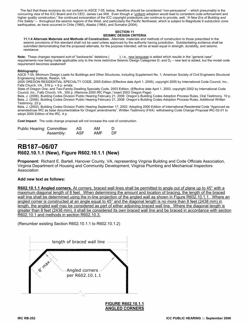
RB187–06/07 R602.10.1.1 (New), Figure R602.10.1.1 (New) Proponent: Richard E. Bartell, Hanover County, VA, representing Virginia Building and Code Officials Association, Virginia Department of Housing and Community Development, Virginia Plumbing and Mechanical Inspectors Association Add new text as follows: R602.10.1.1 Angled corners. At corners, braced wall lines shall be permitted to angle out of plane up to 45° with a maximum diagonal length of 8 feet. When determining the amount and location of bracing, the length of the braced wall line shall be determined using the in-line projection of the angled wall as shown in Figure R602.10.1.1. Where an angled corner is constructed at an angle equal to 45° and the diagonal length is no more than 8 feet (2438 mm) in length, the angled wall may be considered as part of either adjoining braced wall line. Where the diagonal length is greater than 8 feet (2438 mm), it shall be considered its own braced wall line and be braced in accordance with section R602.10.1 and methods in section R602.10.3. (Renumber existing Section R602.10.1.1 to R602.10.1.2)
Angled cornersper R602.10.1.1
8' m
ax.
length of braced wall line
FIGURE R602.10.1.1 ANGLED CORNERS
ICC PUBLIC HEARING ::: September 2006 IRC RB-253
Reason: To address a common design practice within the prescriptive requirements of the code. Many new single family dwellings and additions are designed with angled corners as a design element. The code currently has no provisions that address how to apply the braced wall line provisions to these corners. The angled corner can take a component of the load being transferred along the braced wall line. The magnitude of this component varies with the angle created between the wall line and the corner. The greater the angle, the lower the magnitude of the load. For this reason the length of wall added to the braced wall line is equal to the projected length as shown in the figure, not the actual length. The eight foot maximum length is to stay consistent with the offset limits in R602.10.1. Cost Impact: The code change proposal will not increase the cost of construction. Public Hearing: Committee: AS AM D Assembly: ASF AMF DF
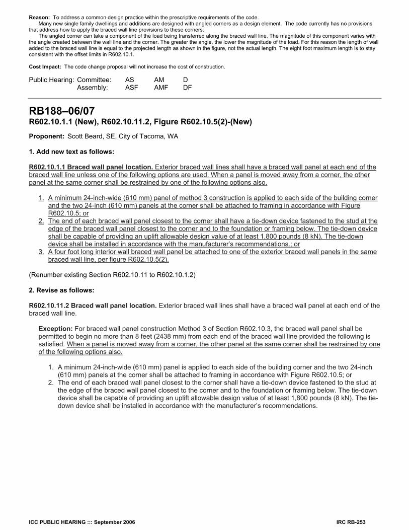
RB188–06/07 R602.10.1.1 (New), R602.10.11.2, Figure R602.10.5(2)-(New) Proponent: Scott Beard, SE, City of Tacoma, WA 1. Add new text as follows: R602.10.1.1 Braced wall panel location. Exterior braced wall lines shall have a braced wall panel at each end of the braced wall line unless one of the following options are used. When a panel is moved away from a corner, the other panel at the same corner shall be restrained by one of the following options also.
1. A minimum 24-inch-wide (610 mm) panel of method 3 construction is applied to each side of the building corner and the two 24-inch (610 mm) panels at the corner shall be attached to framing in accordance with Figure R602.10.5; or 2. The end of each braced wall panel closest to the corner shall have a tie-down device fastened to the stud at the edge of the braced wall panel closest to the corner and to the foundation or framing below. The tie-down device shall be capable of providing an uplift allowable design value of at least 1,800 pounds (8 kN). The tie-down device shall be installed in accordance with the manufacturer’s recommendations.; or 3. A four foot long interior wall braced wall panel be attached to one of the exterior braced wall panels in the same braced wall line, per figure R602.10.5(2).
(Renumber existing Section R602.10.11 to R602.10.1.2)
2. Revise as follows: R602.10.11.2 Braced wall panel location. Exterior braced wall lines shall have a braced wall panel at each end of the braced wall line.
Exception: For braced wall panel construction Method 3 of Section R602.10.3, the braced wall panel shall be permitted to begin no more than 8 feet (2438 mm) from each end of the braced wall line provided the following is satisfied. When a panel is moved away from a corner, the other panel at the same corner shall be restrained by one of the following options also.
1. A minimum 24-inch-wide (610 mm) panel is applied to each side of the building corner and the two 24-inch (610 mm) panels at the corner shall be attached to framing in accordance with Figure R602.10.5; or 2. The end of each braced wall panel closest to the corner shall have a tie-down device fastened to the stud at the edge of the braced wall panel closest to the corner and to the foundation or framing below. The tie-down device shall be capable of providing an uplift allowable design value of at least 1,800 pounds (8 kN). The tie- down device shall be installed in accordance with the manufacturer’s recommendations.
IRC RB-254 ICC PUBLIC HEARING ::: September 2006
3. Add new figure as follows:
FIGURE R602.10.5(2) ALTERNATE CORNER BRACING
Reason: This proposal plugs a serious structural flaw in the current IRC provisions. It also provides a new structurally acceptable method to mitigate the effects of the main proposal. The problem is that when the end panels are moved away from the corner, it materially impacts the structural capacity of the wall bracing. This will be explained further in the more technical portion of this supporting information. Historically, 4’ wide bracing panels (or let-in braces) have always been required at the corners of prescriptively braced buildings. This can be seen by reviewing older UBC’s and CABO residential Codes. If you drive through the older neighborhoods in town, notice that all of the houses have braced panels at the corners. There are no window corners, except where they have recently remodeled. When we point to historical performance of prescriptive construction, we are pointing to houses with corner panels. Moving the panels away from the corners is something very recent. Even as recently as the ’98 CABO, corner panels were required. The first change came with the ’94 UBC. A review of the code proposal shows that it did not provide technical justification for the change. It quietly slipped under the radar of the structural engineers. How does it affect the structure? A lot of the historical provision relied on poorly understood ‘system effects’. We understand these system effects much better today. The basis for our current provisions is that the braced wall line is being treated as a “Perforated Shear Wall”, which is now a well understood structural system. Perforated Shear Walls traditionally have holddowns at each end. On the basis of two different tests done by Dan Dolan, and by NAHB, these holddown have been replaced by building corners. The corner effect provides the necessary holddown. When a panel is moved away from the corner, we loose the holddown effect. Without holddowns, the Perforated Shear Wall Method no longer applies, and cannot accurately predict the strength of the braced wall assembly. Fortunately, we do have an accurate method for determining the strength of braced wall assemblies without holddown. It is a method developed by Forintek, and has been incorporated into the Canadian building code. It has been well tested, even cyclically tested. The Canadian method tells us that as soon as we move the panel away from the corner, if we don’t provide a holddown for it, it looses 2/3rds of its capacity. Overall, the braced wall line looses about half its capacity. The writers of the high seismic section of the provisions recognized this, and required a holddown if the panel moves away from the corner. Unfortunately, the writers for low seismic missed this. It needs to be remedied. Something that was missed for both high and low seismic, was that as soon as you move the panel away from the corner, the remaining panel on the adjacent wall no longer has a corner brace. This panel also needs a holddown. A new option has been added. The Canadian method shows us that it doesn’t really matter which panels get the corners. We just need to be sure that one braced panel in a wall run has a left-hand corner, and another braced panel has a right hand corner. In low wind, we are providing the possibility for that corner to be provided by one of the inside walls, rather than by a holddown. We are using a 4 ft corner, rather than a 2 ft corner, because this corner is not tied to a foundation but rather is held in place by the ceiling and floor joists. We are not providing this option in high seismic areas. This is because this assembly has not been cyclically tested, as well as the fact that high seismic contractors are used to holddowns, and an $8.50 foundation strap doesn’t scare them like it currently does the low seismic contractors. Cost Impact: The code change proposal will increase the cost of construction. Much of that cost is mitigated by a new bracing method that will not increase the cost. This is one of those cases where it costs more meet your required lateral load, than it does to make something that won’t be strong enough. Public Hearing: Committee: AS AM D Assembly: ASF AMF DF
RB189–06/07 Table R602.10.1, Table R602.10.3(1)-(New), Table R602.10.3(2)-(New) Proponent: James Bela, Oregon Earthquake Awareness, representing same 1. Delete table and substitute as follows:
TABLE R602.10.1 WALL BRACING
(Delete entire table)
Inside braced panel applied on side of exterior braced wall panel closest to corner.
Corner 4 ft minimum 2 ft maximum
4 ft minimum method 2,3,4,5,6, 7, or 8 panel
Attach studs per Figure R602.10.5
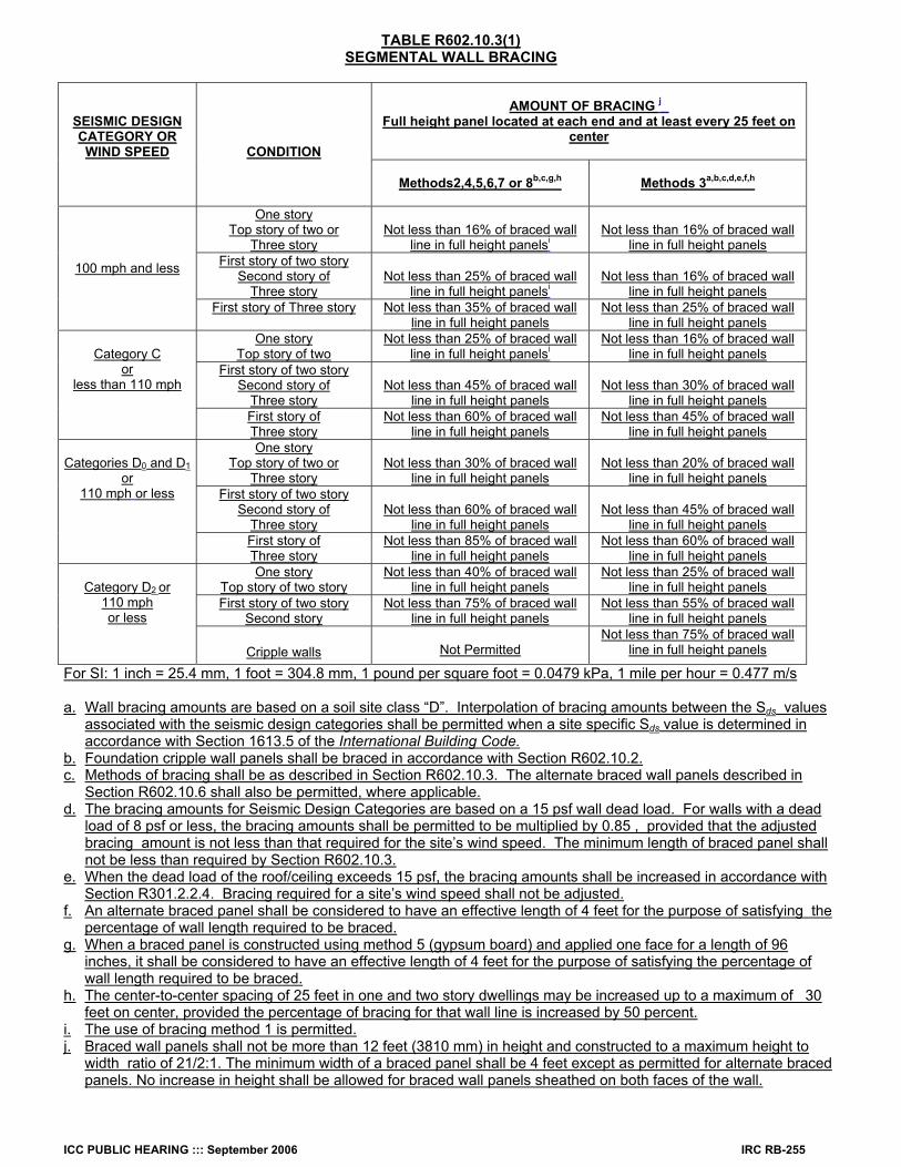
ICC PUBLIC HEARING ::: September 2006 IRC RB-255
TABLE R602.10.3(1) SEGMENTAL WALL BRACING
AMOUNT OF BRACING j_ Full height panel located at each end and at least every 25 feet on
center
SEISMIC DESIGN CATEGORY OR WIND SPEED
CONDITION
Methods2,4,5,6,7 or 8b,c,g,h
Methods 3a,b,c,d,e,f,h
One story Top story of two or
Three story
Not less than 16% of braced wall
line in full height panelsi
Not less than 16% of braced wall
line in full height panels First story of two story
Second story of Three story
Not less than 25% of braced wall
line in full height panelsi
Not less than 16% of braced wall
line in full height panels
100 mph and less
First story of Three story Not less than 35% of braced wall line in full height panels
Not less than 25% of braced wall line in full height panels
One story Top story of two
Not less than 25% of braced wall line in full height panelsi
Not less than 16% of braced wall line in full height panels
First story of two story Second story of
Three story
Not less than 45% of braced wall
line in full height panels
Not less than 30% of braced wall
line in full height panels
Category C
or less than 110 mph
First story of Three story
Not less than 60% of braced wall line in full height panels
Not less than 45% of braced wall line in full height panels
One story Top story of two or
Three story
Not less than 30% of braced wall
line in full height panels
Not less than 20% of braced wall
line in full height panels First story of two story
Second story of Three story
Not less than 60% of braced wall
line in full height panels
Not less than 45% of braced wall
line in full height panels
Categories D0 and D1
or 110 mph or less
First story of Three story
Not less than 85% of braced wall line in full height panels
Not less than 60% of braced wall line in full height panels
One story Top story of two story
Not less than 40% of braced wall line in full height panels
Not less than 25% of braced wall line in full height panels
First story of two story Second story
Not less than 75% of braced wall line in full height panels
Not less than 55% of braced wall line in full height panels
Category D2 or
110 mph or less
Cripple walls
Not Permitted Not less than 75% of braced wall
line in full height panels
For SI: 1 inch = 25.4 mm, 1 foot = 304.8 mm, 1 pound per square foot = 0.0479 kPa, 1 mile per hour = 0.477 m/s a. Wall bracing amounts are based on a soil site class “D”. Interpolation of bracing amounts between the Sds values
associated with the seismic design categories shall be permitted when a site specific Sds value is determined in accordance with Section 1613.5 of the International Building Code.
b. Foundation cripple wall panels shall be braced in accordance with Section R602.10.2. c. Methods of bracing shall be as described in Section R602.10.3. The alternate braced wall panels described in
Section R602.10.6 shall also be permitted, where applicable. d. The bracing amounts for Seismic Design Categories are based on a 15 psf wall dead load. For walls with a dead
load of 8 psf or less, the bracing amounts shall be permitted to be multiplied by 0.85 , provided that the adjusted bracing amount is not less than that required for the site’s wind speed. The minimum length of braced panel shall not be less than required by Section R602.10.3.
e. When the dead load of the roof/ceiling exceeds 15 psf, the bracing amounts shall be increased in accordance with Section R301.2.2.4. Bracing required for a site’s wind speed shall not be adjusted.
f. An alternate braced panel shall be considered to have an effective length of 4 feet for the purpose of satisfying the percentage of wall length required to be braced.
g. When a braced panel is constructed using method 5 (gypsum board) and applied one face for a length of 96 inches, it shall be considered to have an effective length of 4 feet for the purpose of satisfying the percentage of wall length required to be braced.
h. The center-to-center spacing of 25 feet in one and two story dwellings may be increased up to a maximum of 30 feet on center, provided the percentage of bracing for that wall line is increased by 50 percent.
i. The use of bracing method 1 is permitted. j. Braced wall panels shall not be more than 12 feet (3810 mm) in height and constructed to a maximum height to
width ratio of 21/2:1. The minimum width of a braced panel shall be 4 feet except as permitted for alternate braced panels. No increase in height shall be allowed for braced wall panels sheathed on both faces of the wall.
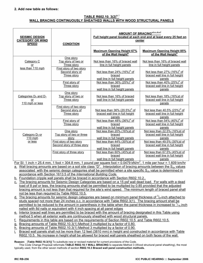
IRC RB-256 ICC PUBLIC HEARING ::: September 2006
2. Add new table as follows:
TABLE R602.10. 3(2)a, i WALL BRACING CONTINUOUSLY SHEATHED WALLS WITH WOOD STRUCTURAL PANELS
AMOUNT OF BRACINGa,b,c,d,e,f Full height panel located at each end and at least every 25 feet on
center
SEISMIC DESIGN CATEGORY OR WIND
SPEED
CONDITION
Maximum Opening Height 67% of the Wall Heightg
Maximum Opening Height 85%
of the Wall Heighth One story
Top story of two or Three story
Not less than 16% of braced wall
line in full height panels
Not less than 16% of braced wall
line in full height panels First story of two story
Second story of Three story
Not less than 24% (16%)d of
braced wall line in full height panels
Not less than 27% (16%)d of braced wall line in full height
panels
Category C
or less than 110 mph
First story of Three story
Not less than 36% (25%)d of braced
wall line in full height panels
Not less than 40% (25%)d of braced wall line in full height
panels One story
Top story of two or Three story
Not less than 16% of braced wall line in full height panels
Not less than 18% (16%)d of braced wall line in full height
panels First story of two story
Second story of Three story
Not less than 36% (20.5%)d of braced wall line in full height
panels
Not less than 40.5% (23%)d of braced wall line in full height
panels
Categories D0 and D1
or 110 mph or less
First story of Three story
Not less than 48% (36%)d of braced
wall line in full height panels
Not less than 54% (40%)d of braced wall line in full height
panels One story
Top story of two or three story
Not less than 20% (16%)d of braced
wall line in full height panels
Not less than 22.5% (16%)d of braced wall line in full height
panels First story of two story Second story of three story
Not less than 44% (30%)d of braced
wall line in full height panels
Not less than 49.5% (30%)d of braced wall line in full height
panels
Category D2 or
110 mph or less
First story of three story Not less than 60% (45%)d of braced
wall line in full height panels
Not less than 67.5% (45%)d of braced wall line in full height
panels For SI: 1 inch = 25.4 mm, 1 foot = 304.8 mm, 1 pound per square foot = 0.0479 kN/m2, 1 mile per hour = 1.609 km/hr a. Wall bracing amounts are based on a soil site class “D”. Interpolation of bracing amounts between the Sds values
associated with the seismic design categories shall be permitted when a site specific Sds value is determined in accordance with Section 1613.5 of the International Building Code.
b. Foundation cripple wall panels shall be braced in accordance with Section R602.10.2.. c. The bracing amounts for Seismic Design Categories are based on a 15 psf wall dead load. For walls with a dead
load of 8 psf or less, the bracing amounts shall be permitted to be multiplied by 0.85 provided that the adjusted bracing amount is not less than that required for the site’s wind speed. The minimum length of braced panel shall not be less than required by Table R602.10.5.
d. The bracing amounts for seismic design categories are based on minimum panel thickness of 3/8-inch attached to studs spaced not more than 24 inches o.c. in accordance with Table R602.3(1). The bracing amount shall be permitted to be reduced to the amount in parenthesis in the table when the panel thickness in increased to 7/16 inch nailed with 8d nails or equivalent with 4 inch spacing at all panel edges
e. Interior braced wall lines are permitted to be braced with the amount of bracing designated in this Table using method 5 when all exterior walls are continuously sheathed with wood structural panels.
f. Requirements in this table are based on the requirements of Section R602.10.5 and Table R602.10.5. g. Bracing amounts of Table R602.10.3(1) Method 3 multiplied by a factor of 0.80. h. Bracing amounts of Table R602.10.3(1) Method 3 multiplied by a factor of 0.90. i. Braced wall panels shall not be more than 12 feet (3810 mm) in height and constructed in accordance with Table
R602.10.5. No increase in height shall be allowed for braced wall panels sheathed on both faces of the wall. Reason: [Table R602.10.3(1)] To substitute new or revised material for current provisions of the Code. This Code Change Proposal reformats TABLE R602.10.1 WALL BRACING to separate Method 3 (Wood structural panel sheathing), the most typically used, from the other seven methods of section R602.10.3 Braced wall panel construction methods.
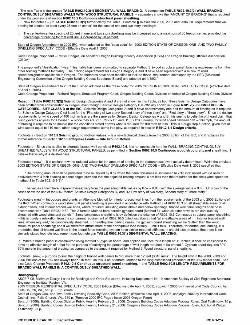
ICC PUBLIC HEARING ::: September 2006 IRC RB-257
The new Table is designated TABLE R602.10.3(1) SEGMENTAL WALL BRACING. A companion TABLE R602.10.3(2) WALL BRACING CONTINUOUSLY SHEATHED WALLS WITH WOOD STRUCTURAL PANELS. – separately shows the “AMOUNT OF BRACING” that is required under the provisions of section R602.10.5 Continuous structural panel sheathing. New footnotes f – j to TABLE R602.10.3(1) further clarify the Table. Footnote h relaxes the 2000, 2003 and 2006 IRC requirements that wall bracing be located “at least every 25 feet on center” for the case of one and two story dwellings: h. The center-to-center spacing of 25 feet in one and two story dwellings may be increased up to a maximum of 30 feet on center, provided the
percentage of bracing for that wall line is increased by 50 percent. State of Oregon Amendment to 2000 IRC; when adopted as the “base code” for 2003 EDITION STATE OF OREGON ONE- AND TWO-FAMILY DWELLING SPECIALTY CODE - Effective Date April 1, 2003 Code Change Proponent – Patrick Bridges: on behalf of Oregon Building Industry Association (OBIA) and Oregon Building Officials Association (OBOA) The proponent’s “Justification” was: “This Table has been reformatted to separate Method 3 (wood structural panel) bracing requirements from the other bracing methods for clarity. The bracing requirements for Design Category A and B have been replaced with a minimum wind speed designation applicable in Oregon. The footnotes have been modified to include those requirement developed by the SEC [Structural Engineering Committee of the Oregon Building Codes Structures Board] and adopted on 4/1/02.” State of Oregon Amendment to 2003 IRC: when adopted as the “base code” for 2005 OREGON RESIDENTIAL SPECIALTY CODE (effective date of April 1, 2005) Code Change Proponent – Richard Rogers, Structural Program Chief, Oregon Building Codes Division: on behalf of Oregon Building Codes Division Reason: [Table R602.10.3(2)] Seismic Design Categories A and B are not shown in this Table, as both these Seismic Design Categories have been omitted from consideration in Oregon; even though Seismic Design Category B is officially shown in Figure R301.2(2) SEISMIC DESIGN CATEGORIES---SITE CLASS D of the IRC. Seismic Design Categories A and B have approximately one-half the amount of bracing as is required for Seismic Design Category C (at least for the “First story of two story/ Second story of three story” and “First story of three story”. Since the design requirements for wind speed of 100 mph or less are the same as for Seismic Design Categories A and B, this seems to belie the oft heard claim that “wind governs anyway for a house.” -- since they are 2x c; 2x-3x D0 and D1; 3x D2Curiously, for wind speed between 101 – 109 mph, the amount of bracing is required to be double (for the conditions stated above) what is required for 100 mph or less. This is a huge step function, given that at wind speed equal to 110 mph, other design requirements come into play, as required in section R301.2.1.1 Design criteria. Footnote a - Section 1613.5 Seismic ground motion values. – is a new technical change from the 2003 Edition of the IBC; and it replaces the former reference to Section 1615 Earthquake Loads --- Site Ground Motion. Footnote c – Since this applies to alternate braced wall panels of R602.10.6, it is not applicable here for WALL BRACING CONTINUOUSLY SHEATHED WALLS WITH WOOD STRUCTURAL PANELS, as permitted in Section R602.10.5 Continuous wood structural panel sheathing. I believe that is why it is deleted here. Footnote d (new) – It is unclear how the reduced values for the amount of bracing in the (parentheses) was actually determined. While the previous 2003 EDITION STATE OF OREGON ONE- AND TWO-FAMILY DWELLING SPECIALTY CODE – Effective Date April 1, 2003 specified that: “The bracing amount shall be permitted to be multiplied by 0.57 when the panel thickness is increased to 7/16 inch nailed with 8d nails or equivalent with 4 inch spacing at panel edges provided that the adjusted bracing amount is not less than that required for the site’s wind speed for method 3 in Table 602.10.3(1).” The values shown here in (parentheses) vary from the preceding table values by 0.57 – 0.80 (with the average value = 0.65. Only two of the cases show the use of the 0.57 factor: Seismic Design Categories D0 and D1: First story of two story, Second story of Three story.” Footnote e (new) – Introduces and grants an Alternate Method for interior braced wall lines from the requirements of the 2003 and 2006 Editions of the IRC: “When continuous wood structural panel sheathing is provided in accordance with Method 3 of R602.10.3 on all sheathable areas of all exterior walls, and interior braced wall lines, where required, including areas above and below openings, braced wall panel lengths shall be in accordance with Table R602.10.5.” This Alternate Method here permits gypsum board (Method 5) “when all exterior walls are continuously sheathed with wood structural panels.” Since continuous sheathing is by definition the criterion of R602.10.5 Continuous structural panel sheathing. – this is purely a relaxation from the concurrent requirement of R602.10.5 (cited just above) that “all sheathable areas of . . . interior braced wall lines, where required,” be continuously sheathed. For earthquake loading cases, the gypsum board sheathing will be “stiffer” than the wood structural panel sheathing; and it will therefore attract more of the earthquake load initially – until it fails. Therefore, for earthquake loading, it is preferable that all braced wall lines in the lateral-force-resisting-system have similar material stiffness. It should also be noted that there is no similarly stated footnote requirement (per footnote g in TABLE R602.10.3(1) SEGMENTAL WALL BRACING: g. When a braced panel is constructed using method 5 (gypsum board) and applied one face for a length of 96 inches, it shall be considered to have an effective length of 4 feet for the purpose of satisfying the percentage of wall length required to be braced.” Gypsum board requires 30% – 60% more in the amount of bracing, as compared to the amount required for Method 3: Wood structural panel sheathing. Footnote i (new) – purports to limit the height of braced wall panels to “not more than 12 feet (3810 mm)”. The height limit in the 2000, 2003 and 2006 Editions of the IRC has always been “10 feet”; so this is an Alternate Method to the long established precedent of the IRC model code. See also Code Change Proposals R602.10.5 Continuous structural panel sheathing. – and TABLE R602.10.5 LENGTH REQUIREMENTS FOR BRACED WALL PANELS IN A CONTINUOUSLY SHEATHED WALL. Bibliography: ASCE 7-05, Minimum Design Loads for Buildings and Other Structures, including Supplement No. 1; American Society of Civil Engineers Structural Engineering Institute, Reston, VA. 2005 OREGON RESIDENTIAL SPECIALTY CODE, 2005 Edition (Effective date April 1, 2005), copyright 2005 by International Code Council, Inc., Falls Church, VA., 516 p. + 6 p. errata. State of Oregon One- and Two-Family Dwelling Specialty Code, 2003 Edition, (Effective date April 1, 2003, copyright 2002 by International Code Council, Inc., Falls Church, VA., 350 p. (Remove 2000 IRC Page / Insert 2003 Oregon Page) Bela, J. (2006). Building Codes Division Public Hearing February 21, 2006: Oregon’s Building Codes Adoption Process Rules, Oral Testimony, 10 p. Bela, J. (2006). Building Codes Division Public Hearing February 21, 2006: Oregon’s Building Codes Adoption Process Rules, Additional Written Testimony, 23 p.
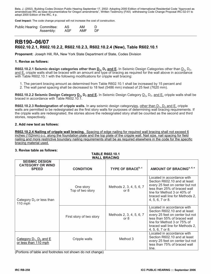
IRC RB-258 ICC PUBLIC HEARING ::: September 2006
Bela, J. (2002). Building Codes Division Public Hearing September 17, 2002: Adopting 2000 Edition of International Residential Code “Approved as amended/use IRC as base document/allow for Oregon amendments”, Written Testimony (FAX) withdrawing Code Change Proposal IRC-02-01 to adopt 2000 Edition of the IRC, 4 p. Cost Impact: The code change proposal will not increase the cost of construction. Public Hearing: Committee: AS AM D Assembly: ASF AMF DF
RB190–06/07 R602.10.2.1, R602.10.2.2, R602.10.2.3, R602.10.2.4 (New), Table R602.10.1 Proponent: Joseph Hill, RA, New York State Department of State, Codes Division 1. Revise as follows: R602.10.2.1 Seismic design categories other than D1, D2 and E. In Seismic Design Categories other than D1, D2, and E, cripple walls shall be braced with an amount and type of bracing as required for the wall above in accordance with Table R602.10.1 with the following modifications for cripple wall bracing:
1. The percent bracing amount as determined from Table R602.10.1 shall be increased by 15 percent and 2. The wall panel spacing shall be decreased to 18 feet (5486 mm) instead of 25 feet (7620 mm).
R602.10.2.2 Seismic Design Category D1, D2 and E. In Seismic Design Category D1, D2, and E, cripple walls shall be braced in accordance with Table R602.10.1. R602.10.2.3 Redesignation of cripple walls. In any seismic design categoryies, other than D1, D2 and E, cripple walls are permitted to be redesignated as the first story walls for purposes of determining wall bracing requirements. If the cripple walls are redesignated, the stories above the redesignated story shall be counted as the second and third stories, respectively. 2. Add new text as follows: R602.10.2.4 Nailing of cripple wall bracing. Spacing of edge nailing for required wall bracing shall not exceed 6 inches (152mm) o.c. along the foundation plate and the top plate of the cripple wall. Nail size, nail spacing for field nailing and more restrictive boundary nailing requirements shall be as required elsewhere in the code for the specific bracing material used. 3. Revise table as follows:
TABLE R602.10.1 WALL BRACING
SEISMIC DESIGN CATEGORY OR WIND
SPEED
CONDITION
TYPE OF BRACEb, c
AMOUNT OF BRACINGa, d, e
One story Top of two story
Methods 2, 3, 4, 5, 6, 7 or 8
Located in accordance with Section R602.10 and at least every 25 feet on center but not less than 25% of braced wall line for Method 3 or 40% of braced wall line for Methods 2, 4, 5, 6, 7 or 8.
Category D2 or less than 110 mph
First story of two story
Methods 2, 3, 4, 5, 6, 7 or 8
Located in accordance with Section R602.10 and at least every 25 feet on center but not less than 55% of braced wall line for Method 3 or 75% of braced wall line for Methods 2, 4, 5, 6, 7 or 8.
Category D1, D2 and E or less than 110 mph
Cripple walls
Method 3
Located in accordance with Section R602.10 and at least every 25 feet on center but not less than 75% of braced wall line.
(Portions of table and footnotes not shown do not change)
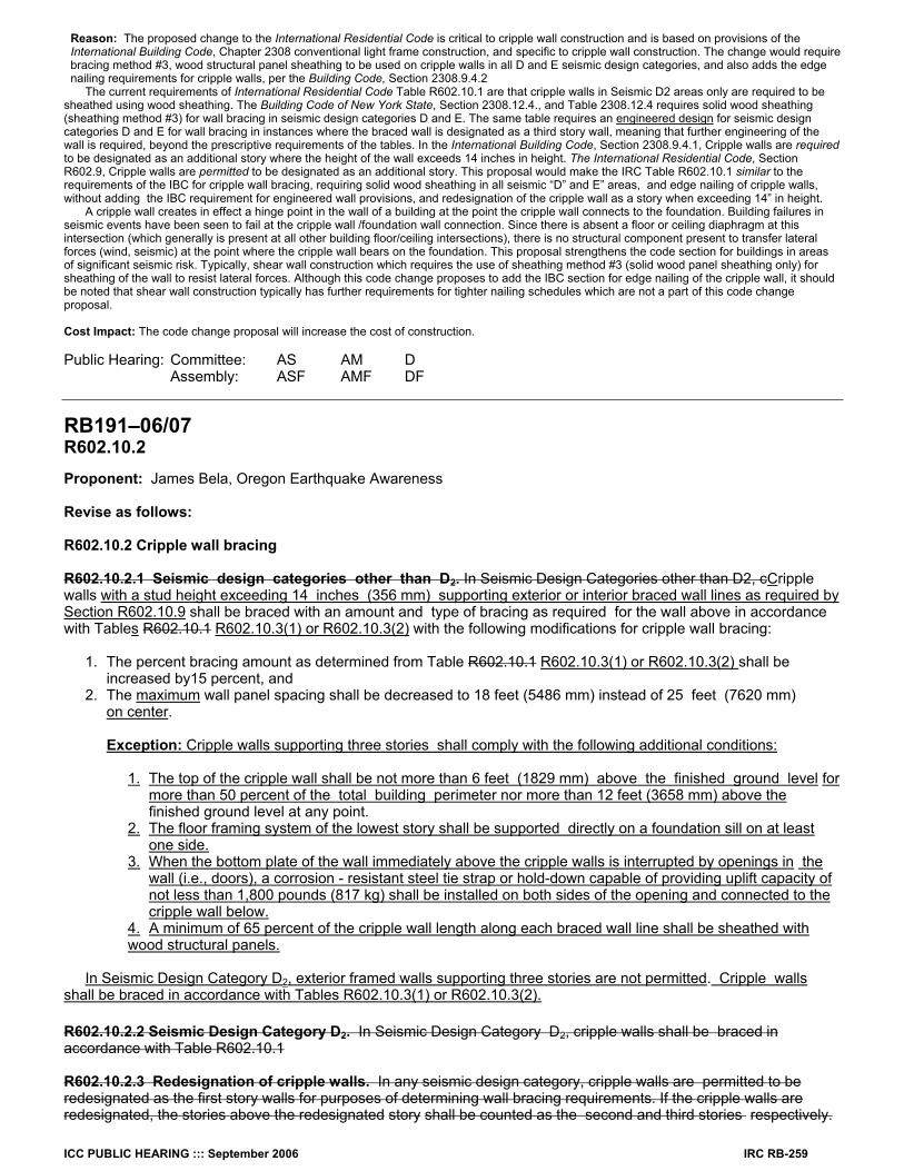
ICC PUBLIC HEARING ::: September 2006 IRC RB-259
Reason: The proposed change to the International Residential Code is critical to cripple wall construction and is based on provisions of the International Building Code, Chapter 2308 conventional light frame construction, and specific to cripple wall construction. The change would require bracing method #3, wood structural panel sheathing to be used on cripple walls in all D and E seismic design categories, and also adds the edge nailing requirements for cripple walls, per the Building Code, Section 2308.9.4.2
The current requirements of International Residential Code Table R602.10.1 are that cripple walls in Seismic D2 areas only are required to be sheathed using wood sheathing. The Building Code of New York State, Section 2308.12.4., and Table 2308.12.4 requires solid wood sheathing (sheathing method #3) for wall bracing in seismic design categories D and E. The same table requires an engineered design for seismic design categories D and E for wall bracing in instances where the braced wall is designated as a third story wall, meaning that further engineering of the wall is required, beyond the prescriptive requirements of the tables. In the International Building Code, Section 2308.9.4.1, Cripple walls are required to be designated as an additional story where the height of the wall exceeds 14 inches in height. The International Residential Code, Section R602.9, Cripple walls are permitted to be designated as an additional story. This proposal would make the IRC Table R602.10.1 similar to the requirements of the IBC for cripple wall bracing, requiring solid wood sheathing in all seismic “D” and E” areas, and edge nailing of cripple walls, without adding the IBC requirement for engineered wall provisions, and redesignation of the cripple wall as a story when exceeding 14” in height. A cripple wall creates in effect a hinge point in the wall of a building at the point the cripple wall connects to the foundation. Building failures in seismic events have been seen to fail at the cripple wall /foundation wall connection. Since there is absent a floor or ceiling diaphragm at this intersection (which generally is present at all other building floor/ceiling intersections), there is no structural component present to transfer lateral forces (wind, seismic) at the point where the cripple wall bears on the foundation. This proposal strengthens the code section for buildings in areas of significant seismic risk. Typically, shear wall construction which requires the use of sheathing method #3 (solid wood panel sheathing only) for sheathing of the wall to resist lateral forces. Although this code change proposes to add the IBC section for edge nailing of the cripple wall, it should be noted that shear wall construction typically has further requirements for tighter nailing schedules which are not a part of this code change proposal. Cost Impact: The code change proposal will increase the cost of construction. Public Hearing: Committee: AS AM D Assembly: ASF AMF DF
RB191–06/07 R602.10.2 Proponent: James Bela, Oregon Earthquake Awareness Revise as follows: R602.10.2 Cripple wall bracing R602.10.2.1 Seismic design categories other than D2. In Seismic Design Categories other than D2, cCripple walls with a stud height exceeding 14 inches (356 mm) supporting exterior or interior braced wall lines as required by Section R602.10.9 shall be braced with an amount and type of bracing as required for the wall above in accordance with Tables R602.10.1 R602.10.3(1) or R602.10.3(2) with the following modifications for cripple wall bracing:
1. The percent bracing amount as determined from Table R602.10.1 R602.10.3(1) or R602.10.3(2) shall be increased by15 percent, and
2. The maximum wall panel spacing shall be decreased to 18 feet (5486 mm) instead of 25 feet (7620 mm) on center.
Exception: Cripple walls supporting three stories shall comply with the following additional conditions:
1. The top of the cripple wall shall be not more than 6 feet (1829 mm) above the finished ground level for
more than 50 percent of the total building perimeter nor more than 12 feet (3658 mm) above the finished ground level at any point.
2. The floor framing system of the lowest story shall be supported directly on a foundation sill on at least one side.
3. When the bottom plate of the wall immediately above the cripple walls is interrupted by openings in the wall (i.e., doors), a corrosion - resistant steel tie strap or hold-down capable of providing uplift capacity of not less than 1,800 pounds (817 kg) shall be installed on both sides of the opening and connected to the cripple wall below.
4. A minimum of 65 percent of the cripple wall length along each braced wall line shall be sheathed with wood structural panels.
In Seismic Design Category D2, exterior framed walls supporting three stories are not permitted. Cripple walls shall be braced in accordance with Tables R602.10.3(1) or R602.10.3(2). R602.10.2.2 Seismic Design Category D2. In Seismic Design Category D2, cripple walls shall be braced in accordance with Table R602.10.1 R602.10.2.3 Redesignation of cripple walls. In any seismic design category, cripple walls are permitted to be redesignated as the first story walls for purposes of determining wall bracing requirements. If the cripple walls are redesignated, the stories above the redesignated story shall be counted as the second and third stories respectively.
IRC RB-260 ICC PUBLIC HEARING ::: September 2006
Reason: To substitute new or revised material for current provisions of the Code. “The Building Code should be a consensus; it’s not something to ‘chip-away’ at, because then you don’t know what you’ve got!” --George Housner Brace yourself! This code change proposal merges everything pertaining to cripple wall bracing into one stew. It encompasses language from the DEFINITION of “STORY ABOVE GRADE”, and under some circumstances may effectively permit 4 story buildings (3 stories above the cripple wall) in Seismic Design Category D1; since the provision to redesignate cripple walls as the “first story” under R602.10.2.3 Redesignation of cripple walls. – has been deleted and therefore lost to the judgement of the Building Official. Cripple walls are not required to be always supported on continuous foundations, as a result of language deleted in R602.9 Cripple walls. Cripple walls may support 3 stories in Seismic Design Category D1 , but without the requirements for 1/4 inch by 3 inches by 3 inches steel “plate washers”, as designated in R602.11.1 Wall anchorage. - but deleted. In Seismic Design Category D2, cripple walls supporting two stories are only anchored to the foundation with steel “plate washers” a minimum of 3/16 inch by 2 inches by 2 or 2 ¼ inches in diameters, the Oregon substituted lesser requirement for foundation anchorage, back to the earlier model code requirement of the 2000 IRC. State of Oregon Amendment to 2000 IRC: Code Change Proponent – Patrick Bridges: on behalf of Oregon Building Industry Association (OBIA) and Oregon Building Officials Association (OBOA) State of Oregon Amendment to 2003 IRC: adopted as the “base code” for 2005 OREGON RESIDENTIAL SPECIALTY CODE (effective date of April 1, 2005) Code Change Proponent – Richard Rogers, Structural Program Chief, Oregon Building Codes Division: on behalf of Oregon Building Codes Division These changes to model code language of the International Residential Code (IRC) were effected by basically just “voting them in” by members of the Oregon Building Codes Division’s (a) code development committees; (b) appropriate Advisory Boards; and (c) finally the concurrence of the BCD Administrator. Where technical supporting information was presented in the Oregon code change process, that same information is presented here. Where none was given in the Oregon code change process, the “supporting information” is “voting yes” in support by all of the above - to change the model code. Finally, one reasonably expects that the Board of Directors of the ICC, the “People Helping People Build a Safer World™” see nothing in conflict with the Vision, Mission and Values of the ICC, since they agreeably have printed them under their copyright ownership now for two code cycles (2003 & 2005: Vision: Protecting the health, safety, and welfare of people by creating better buildings and safer communities. Mission: Providing the highest quality codes, standards, products, and services for all concerned with the safety and performance of the built environment Values: Customer value, Integrity and trust, Member-focus, Professionalism, Public service, Quality The fact that these revisions do not conform to ASCE 7-05, below, therefore should be considered “non-persuasive” – which presumably is the concurring view of the ICC Board and it’s CEO, James Lee Witt. Even though a “uniform adoption would lead to consistent code enforcement and higher quality construction,” the continued evisceration of the ICC copyright protections can continue to provide, well, “A New Era of Building and Fire Safety” -- throughout the seismic regions of the West, and particularly the Pacific Northwest, which is subject to Magnitude 9 subduction zone earthquakes, as have occurred in Chile (1960), Alaska (1964), and Sumatra (2004).
SECTION 11SEISMIC DESIGN CRITERIA 11.1.4 Alternate Materials and Methods of Construction. Alternate materials and methods of construction to those prescribed in the seismic provisions of this standard shall not be used unless approved by the authority having jurisdiction. Substantiating evidence shall be submitted demonstrating that the proposed alternate, for the purpose intended, will be at least equal in strength, durability, and seismic resistance.
Bibliography: ASCE 7-05, Minimum Design Loads for Buildings and Other Structures, including Supplement No. 1; American Society of Civil Engineers Structural Engineering Institute, Reston, VA.2005 OREGON RESIDENTIAL SPECIALTY CODE, 2005 Edition (Effective date April 1, 2005), copyright 2005 by International Code Council, Inc., Falls Church, VA., 516 p. + 6 p. errata. State of Oregon One- and Two-Family Dwelling Specialty Code, 2003 Edition, (Effective date April 1, 2003, copyright 2002 by International Code Council, Inc., Falls Church, VA., 350 p. (Remove 2000 IRC Page / Insert 2003 Oregon Page) Bela, J. (2006). Building Codes Division Public Hearing February 21, 2006: Oregon’s Building Codes Adoption Process Rules, Oral Testimony, 10 p. Bela, J. (2006). Building Codes Division Public Hearing February 21, 2006: Oregon’s Building Codes Adoption Process Rules, Additional Written Testimony, 23 p. Bela, J. (2002). Building Codes Division Public Hearing September 17, 2002: Adopting 2000 Edition of International Residential Code “Approved as amended/use IRC as base document/allow for Oregon amendments”, Written Testimony (FAX) withdrawing Code Change Proposal IRC-02-01 to adopt 2000 Edition of the IRC, 4 p. Cost Impact: The code change proposal will not increase the cost of construction. Public Hearing: Committee: AS AM D Assembly: ASF AMF DF
RB192–06/07 R602.10.2.1 Proponents: Jim W. Sealy and Kelly Cobeen, FEMA/BSSC Code Resource Support Committee Revise as follows: R602.10.2.1 Seismic Design Categories Other Than D2. In Seismic Design Categories other than D2, cripple walls having a stud height of 14 inches or greater shall be considered a story and shall be braced in accordance with Table R602.10.1. with an amount and type of bracing as required for the wall above in accordance with Table R602.10.1 with the following modifications for cripple wall bracing:
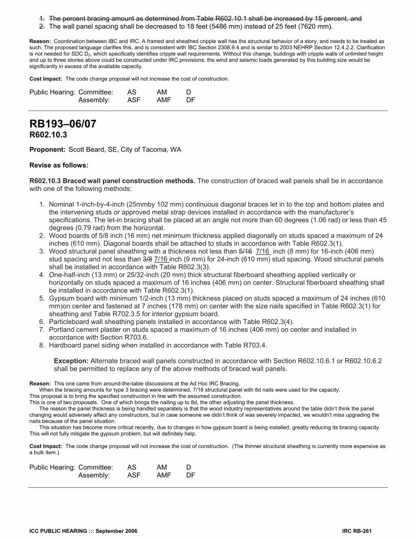
ICC PUBLIC HEARING ::: September 2006 IRC RB-261
1. The percent bracing amount as determined from Table R602.10.1 shall be increased by 15 percent, and 2. The wall panel spacing shall be decreased to 18 feet (5486 mm) instead of 25 feet (7620 mm).
Reason: Coordination between IBC and IRC. A framed and sheathed cripple wall has the structural behavior of a story, and needs to be treated as such. The proposed language clarifies this, and is consistent with IBC Section 2308.9.4 and is similar to 2003 NEHRP Section 12.4.2.2. Clarification is not needed for SDC D2, which specifically identifies cripple wall requirements. Without this change, buildings with cripple walls of unlimited height and up to three stories above could be constructed under IRC provisions; the wind and seismic loads generated by this building size would be significantly in excess of the available capacity. Cost Impact: The code change proposal will not increase the cost of construction. Public Hearing: Committee: AS AM D Assembly: ASF AMF DF
RB193–06/07 R602.10.3 Proponent: Scott Beard, SE, City of Tacoma, WA Revise as follows: R602.10.3 Braced wall panel construction methods. The construction of braced wall panels shall be in accordance with one of the following methods:
1. Nominal 1-inch-by-4-inch (25mmby 102 mm) continuous diagonal braces let in to the top and bottom plates and the intervening studs or approved metal strap devices installed in accordance with the manufacturer’s specifications. The let-in bracing shall be placed at an angle not more than 60 degrees (1.06 rad) or less than 45 degrees (0.79 rad) from the horizontal.
2. Wood boards of 5/8 inch (16 mm) net minimum thickness applied diagonally on studs spaced a maximum of 24 inches (610 mm). Diagonal boards shall be attached to studs in accordance with Table R602.3(1).
3. Wood structural panel sheathing with a thickness not less than 5/16 7/16 inch (8 mm) for 16-inch (406 mm) stud spacing and not less than 3/8 7/16 inch (9 mm) for 24-inch (610 mm) stud spacing. Wood structural panels shall be installed in accordance with Table R602.3(3).
4. One-half-inch (13 mm) or 25/32-inch (20 mm) thick structural fiberboard sheathing applied vertically or horizontally on studs spaced a maximum of 16 inches (406 mm) on center. Structural fiberboard sheathing shall be installed in accordance with Table R602.3(1).
5. Gypsum board with minimum 1/2-inch (13 mm) thickness placed on studs spaced a maximum of 24 inches (610 mm)on center and fastened at 7 inches (178 mm) on center with the size nails specified in Table R602.3(1) for sheathing and Table R702.3.5 for interior gypsum board.
6. Particleboard wall sheathing panels installed in accordance with Table R602.3(4). 7. Portland cement plaster on studs spaced a maximum of 16 inches (406 mm) on center and installed in
accordance with Section R703.6. 8. Hardboard panel siding when installed in accordance with Table R703.4.
Exception: Alternate braced wall panels constructed in accordance with Section R602.10.6.1 or R602.10.6.2 shall be permitted to replace any of the above methods of braced wall panels.
Reason: This one came from around-the-table discussions at the Ad Hoc IRC Bracing. When the bracing amounts for type 3 bracing were determined, 7/16 structural panel with 8d nails were used for the capacity. This proposal is to bring the specified construction in line with the assumed construction. This is one of two proposals. One of which brings the nailing up to 8d, the other adjusting the panel thickness. The reason the panel thickness is being handled separately is that the wood industry representatives around the table didn’t think the panel changing would adversely affect any constructors, but in case someone we didn’t think of was severely impacted, we wouldn’t miss upgrading the nails because of the panel situation. This situation has become more critical recently, due to changes in how gypsum board is being installed, greatly reducing its bracing capacity. This will not fully mitigate the gypsum problem, but will definitely help. Cost Impact: The code change proposal will not increase the cost of construction. (The thinner structural sheathing is currently more expensive as a bulk item.) Public Hearing: Committee: AS AM D Assembly: ASF AMF DF
IRC RB-262 ICC PUBLIC HEARING ::: September 2006
RB194–06/07 R602.10.3 Proponent: Scott Beard, SE, City of Tacoma, WA, representing same Revise as follows: R602.10.3 Braced wall panel construction methods. The construction of braced wall panels shall be in accordance with one of the following methods:
1. Nominal 1-inch-by-4-inch (25mmby 102 mm) continuous diagonal braces let in to the top and bottom plates and the intervening studs or approved metal strap devices installed in accordance with the manufacturer’s specifications. The let-in bracing shall be placed at an angle not more than 60 degrees (1.06 rad) or less than 45 degrees (0.79 rad) from the horizontal.
2. Wood boards of 5/8 inch (16 mm) net minimum thickness applied diagonally on studs spaced a maximum of 24 inches (610 mm). Diagonal boards shall be attached to studs in accordance with Table R602.3(1).
3. Wood structural panel sheathing with a thickness not less than 5/16 inch (8 mm) for 16-inch (406 mm) stud spacing and not less than 3/8 inch (9 mm) for 24-inch (610 mm) stud spacing. Wood structural panels shall be installed in accordance with Table R602.3(3).
4. One-half-inch (13 mm) or 25/32-inch (20 mm) thick structural fiberboard sheathing applied vertically or horizontally on studs spaced a maximum of 16 inches (406 mm) on center. Structural fiberboard sheathing shall be installed in accordance with Table R602.3(1).
5. Gypsum board with minimum 1/2-inch (13 mm) thickness placed on studs spaced a maximum of 24 inches (610 mm)on center and fastened at 7 inches (178 mm) on center with the size nails specified in Table R602.3(1) for sheathing and Table R702.3.5 for interior gypsum board.
6. Particleboard wall sheathing panels installed in accordance with Table R602.3(4). 7. Portland cement plaster on studs spaced a maximum of 16 inches (406 mm) on center and installed in
accordance with Section R703.6. 8. Hardboard panel siding when installed in accordance with Table R703.4.
Exception: Alternate braced wall panels constructed in accordance with Section R602.10.6.1 or R602.10.6.2 shall be permitted to replace any of the above methods of braced wall panels.
All gypsum board, including gypsum board that is not part of a braced wall panel, shall be fastened to studs, and bottom and top plates at 8 inches on center maximum.
Exception: Gypsum board in buildings designed by the Wood Framed Construction Manual or SSTD 10 only have to comply with the above spacing at bracing panel locations that use gypsum board as part of the lateral bracing system.
Reason: The gypsum board industry has never been interested in using gypsum board for bracing. They will get their sales regardless. All that using it for bracing gets them is more liability. Their bigger concern is minimizing cracking. As a result, recently they have started recommending for installation of gypsum board, not to attach to the bottom or top plate, and to let the first panel into a corner float without attachment. We are awaiting structural test results, but in the meantime we can use the analytical methods that accurately predict the strength of other panel materials. The analytical results indicate that if the gypsum board is installed per the new recommendations, they will only have 15% of the expected strength. This is a critical item, because:
a) All forms of IRC bracing have been assumed to have gypboard on the inside face sharing the load. This even includes let-in bracing. It is not called out in the construction methods, but it is there in the assumptions that established the bracing amounts.
b) The IRC bracing amounts include the assumption that approximately 40% of the load is being carried by the interior gypboard walls that are not part of the specified bracing. This is sometimes referred to as a “systems effect”, when panel bracing amounts are being discussed. We are about to loose 85% of this assumed capacity.
We need to have this somewhere where it will be seen, and not just a small print footnote to a table. The WFCM and SSTD 10 do not depend on interior gyp that is not part of the explicit bracing system. They can also be used in a way that does not require any gypboard to act as bracing. As such, they warrant an exception. This provides a way for builders to take advantage of the gypboard industry’s new recommendation to reduce cracking, without having to get engineering for their house design. This is an illustration of the new gypboard nailing, taken from USG’s website:
ICC PUBLIC HEARING ::: September 2006 IRC RB-263
Pacific A 4 Cost Impact: The code change proposal will not increase the cost of construction. (Not if we act quickly. If we let the new detail get widespread, then it would be a very necessary increase.) Public Hearing: Committee: AS AM D Assembly: ASF AMF DF
RB195–06/07 R602.10.3 Proponent: James Bela, Oregon Earthquake Awareness, representing same Revise as follows: R602.10.3 Braced wall panel construction methods. The construction of braced wall panels shall be in accordance with one of the following methods:
1. Nominal 1-inch-by-4-inch (25mmby 102 mm) continuous diagonal braces let in to the top and bottom plates and the intervening studs or approved metal strap devices installed in accordance with the manufacturer’s specifications. The let-in bracing shall be placed at an angle not more than 60 degrees (1.06 rad) or less than 45 degrees (0.79 rad) from the horizontal.
2. Wood boards of 5/8 inch (16 mm) net minimum thickness applied diagonally on studs spaced a maximum of 24 inches (610 mm). Diagonal boards shall be attached to studs in accordance with Table R602.3(1).
3. Wood structural panel sheathing with a thickness not less than 5/16 inch (8 mm) for 16-inch (406 mm) stud spacing and not less than 3/8 inch (9 mm) for 24-inch (610 mm) stud spacing. Wood structural panels shall be installed in accordance with Table R602.3(3).
4. One-half-inch (13 mm) or 25/32-inch (20 mm) thick structural fiberboard sheathing applied vertically or horizontally on studs spaced a maximum of 16 inches (406 mm) on center. Structural fiberboard sheathing shall be installed in accordance with Table R602.3(1).
5. Gypsum board with minimum 1/2-inch (13 mm) thickness placed on studs spaced a maximum of 24 inches (610 mm)on center and fastened at the edge of the panel at 7 inches (178 mm) on center with the size nails specified in Table R602.3(1) for sheathing and Table R702.3.5 for interior gypsum board.
6. Particleboard wall sheathing panels installed in accordance with Table R602.3(4). 7. Portland cement plaster on studs spaced a maximum of 16 inches (406 mm) on center and installed in
accordance with Section R703.6. 8. Hardboard panel siding when installed in accordance with Table R703.4.
Exception: Alternate braced wall panels constructed in accordance with Section R602.10.6.1 or R602.10.6.2 shall be permitted to replace any of the above methods of braced wall panels.
Reason: To substitute new or revised material for current provisions of the Code. “The Building Code should be a consensus; it’s not something to ‘chip-away’ at, because then you don’t know what you’ve got!”-- George Housner Table R702.3.5 MINIMUM THICKNES AND APPLICATION OF GYPSUM BOARD – specifies 8 inch spacings for both 1/2 inch and 5/8 inch GYPSUM BOARD, when placed on framing members spaced 24 inches (610 mm) on center. Presumably, this proposed code change shown above would then allow 8 inch nail spacing everywhere other than at “the edge of the panel.”
IRC RB-264 ICC PUBLIC HEARING ::: September 2006
Table R602.3(1) FASTENER SCHEDULE FOR STRUCTURAL MEMBERS – specifies 4 inch “edge nailing” for both 1/2 inch and 5/8 inch “gypsum sheathing”; and 8 inch nailing at “intermediate supports.” Paragraph 5 is unclear, regarding how to nail “gypsum sheathing”, if it were to be used (if it can be) as a “Braced wall panel construction method” of R602.10.3. TABLE R602.3(1) FASTENER SCHEDULE FOR STRUCTURAL MEMBERS specifies different nails (for gypsum wall sheathing) than TABLE R702.3.5 MAXIMUM THICKNESS AND APPLICATION OF GYPSUM BOARD – and it also permits “staple galvanized, 1 ½” long; 1 5/8” screws, Type W or S”. For seismic applications, nails are preferable to staples and screws; and nails with “washers” perform even better. The language of Paragraph does say “with the size nails specified in Table R602.3(1) for sheathing”, but this is ripe for confusion in construction practice! It is clear that “4 inches – edge spacing of fasteners” is not the same as “fastened at 7 inches (178 mm) on center”; and probably the only way to make this clear is to have separate paragraphs for “gypsum board” and “gypsum sheathing”. “It’s all very simple, or it’s very complex; perhaps it’s neither, maybe both!” State of Oregon Amendment to 2000 IRC: Code Change Proponent – Patrick Bridges: on behalf of Oregon Building Industry Association (OBIA) and Oregon Building Officials Association (OBOA) State of Oregon Amendment to 2003 IRC: adopted as the “base code” for 2005 OREGON RESIDENTIAL SPECIALTY CODE (effective date of April 1, 2005) Code Change Proponent – Richard Rogers, Structural Program Chief, Oregon Building Codes Division: on behalf of Oregon Building Codes Division These changes to model code language of the International Residential Code (IRC) were effected by basically just “voting them in” by members of the Oregon Building Codes Division’s (a) code development committees; (b) appropriate Advisory Boards; and (c) finally the concurrence of the BCD Administrator. Where technical supporting information was presented in the Oregon code change process, that same information is presented here. Where none was given in the Oregon code change process, the “supporting information” is “voting yes” in support by all of the above - to change the model code. Finally, one reasonably expects that the Board of Directors of the ICC, the “People Helping People Build a Safer World™” see nothing in conflict with the Vision, Mission and Values of the ICC, since they agreeably have printed them under their copyright ownership now for two code cycles (2003 & 2005): Vision: Protecting the health, safety, and welfare of people by creating better buildings and safer communities. Mission: Providing the highest quality codes, standards, products, and services for all concerned with the safety and performance of the built environment Values: Customer value, Integrity and trust, Member-focus, Professionalism, Public service, Quality The fact that these revisions do not conform to ASCE 7-05, below, therefore should be considered “non-persuasive” – which presumably is the concurring view of the ICC Board and it’s CEO, James Lee Witt. Even though a “uniform adoption would lead to consistent code enforcement and higher quality construction,” the continued evisceration of the ICC copyright protections can continue to provide, well, “A New Era of Building and Fire Safety” -- throughout the seismic regions of the West, and particularly the Pacific Northwest, which is subject to Magnitude 9 subduction zone earthquakes, as have occurred in Chile (1960), Alaska (1964), and Sumatra (2004).
SECTION 11 SEISMIC DESIGN CRITERIA
11.1.4 Alternate Materials and Methods of Construction. Alternate materials and methods of construction to those prescribed in the seismic provisions of this standard shall not be used unless approved by the authority having jurisdiction. Substantiating evidence shall be submitted demonstrating that the proposed alternate, for the purpose intended, will be at least equal in strength, durability, and seismic resistance.
Bibliography: ASCE 7-05, Minimum Design Loads for Buildings and Other Structures, including Supplement No. 1; American Society of Civil Engineers Structural Engineering Institute, Reston, VA. 2005 OREGON RESIDENTIAL SPECIALTY CODE, 2005 Edition (Effective date April 1, 2005), copyright 2005 by International Code Council, Inc., Falls Church, VA., 516 p. + 6 p. errata. State of Oregon One- and Two-Family Dwelling Specialty Code, 2003 Edition, (Effective date April 1, 2003, copyright 2002 by International Code Council, Inc., Falls Church, VA., 350 p. (Remove 2000 IRC Page / Insert 2003 Oregon Page) Bela, J. (2006). Building Codes Division Public Hearing February 21, 2006: Oregon’s Building Codes Adoption Process Rules, Oral Testimony, 10 p. Bela, J. (2006). Building Codes Division Public Hearing February 21, 2006: Oregon’s Building Codes Adoption Process Rules, Additional Written Testimony, 23 p. Bela, J. (2002). Building Codes Division Public Hearing September 17, 2002: Adopting 2000 Edition of International Residential Code “Approved as amended/use IRC as base document/allow for Oregon amendments”, Written Testimony (FAX) withdrawing Code Change Proposal IRC-02-01 to adopt 2000 Edition of the IRC, 4 p. Cost Impact: The code change proposal will not increase the cost of construction. Public Hearing: Committee: AS AM D Assembly: ASF AMF DF
RB196–06/07 R602.10.3 Proponent: George Thomas, P.E., C.B.O., Pleasanton, CA, representing the Tri-Chapter Code Committee Revise as follows: R602.10.3 Braced wall panel construction methods. The construction of braced wall panels shall be in accordance with one of the following methods:
ICC PUBLIC HEARING ::: September 2006 IRC RB-265
1. Nominal 1-inch-by-4-inch (25mmby 102 mm) continuous diagonal braces let in to the top and bottom plates and the intervening studs or approved metal strap devices installed in accordance with the manufacturer’s specifications. The let-in bracing shall be placed at an angle not more than 60 degrees (1.06 rad) or less than 45 degrees (0.79 rad) from the horizontal.
2. Wood boards of 5/8 inch (16 mm) net minimum thickness applied diagonally on studs spaced a maximum of 24 inches (610 mm). Diagonal boards shall be attached to studs in accordance with Table R602.3(1).
3. Wood structural panel sheathing with a thickness not less than 5/16 inch (8 mm) for 16-inch (406 mm) stud spacing and not less than 3/8 inch (9 mm) for 24-inch (610 mm) stud spacing. Wood structural panels shall be installed in accordance with Table R602.3(3).
4. One-half-inch (13 mm) or 25/32-inch (20 mm) thick structural fiberboard sheathing applied vertically or horizontally on studs spaced a maximum of 16 inches (406 mm) on center. Structural fiberboard sheathing shall be installed in accordance with Table R602.3(1).
5. Gypsum board with minimum ½-inch (12.7 mm) thickness placed on studs spaced a maximum of 24 inches (610 mm) on center and fastened to studs and top and bottom plates at 7 inches (178 mm) on center with the size nails specified in Table R602.3(1) for sheathing and Table R702.3.5 for interior gypsum board.
6. Particleboard wall sheathing panels installed in accordance with Table R602.3(4). 7. Portland cement plaster on studs spaced a maximum of 16 inches (406 mm) on center and installed in
accordance with Section R703.6. 8. Hardboard panel siding when installed in accordance with Table R703.4.
Exception: Alternate braced wall panels constructed in accordance with Section R602.10.6.1 or R602.10.6.2 shall be permitted to replace any of the above methods of braced wall panels.
Reason: To clarify that fasteners for gypsum board used for braced wall panels need to be located along the top and bottom plates, as well as along the studs. The IRC currently does not require a specific pattern of attachment for gypsum board used as braced wall panels, and in the absence of such information gypsum board installers may choose to use the floating edge method of installation, where fasteners are omitted along the top and bottom plates. IBC Section 2508.3.1 prohibits the omission of fasteners along top and bottom plates for shear resisting or fire resistance rated assemblies. Because brace wall panels must perform the same function as shear walls (e.g., resist lateral forces), the IRC should be specific about the expected fastener pattern for braced wall panels using gypsum board. This change would be consistent with IBC Section 2308.9.3 and footnote ‘b’ of IBC Table 2306.4.5 that require braced wall panels using gypsum board to have fasteners along the studs and top and bottom plates. Cost Impact: The code change proposal will not increase the cost of construction. Public Hearing: Committee: AS AM D Assembly: ASF AMF DF
RB197–06/07 R602.10.3.1 (New) Proponent: Randall Shackelford, Simpson Strong-Tie Co. Add new text as follows: R602.10.3.1 Braced Wall Panel Interior Finish Material. Braced wall panels shall have gypsum board installed on the side of the wall opposite the bracing material. Gypsum board shall be not less than ½” in thickness and be fastened in accordance with Table R602.3(1) for sheathing and Table R702.3.5 for interior gypsum board. Exceptions:
1. Wall panels that are braced in accordance with method 5. 2. Wall panels that are braced in accordance with R602.10.6.1. 3. When an approved interior finish material with an in-plane shear resistance equivalent to gypsum board is
installed. Reason: To clarify information in code. Testimony at the Detroit Final Action Hearings, and background information provided to the IRC Sheathing Ad-Hoc Task Group indicated that sheathing percentages in the IRC are based on gypsum board being installed on the opposite face of braced wall panels. Without this gypsum board installed, the braced wall panel will have insufficient capacity and the minimum percent of braced wall listed in the code will be inadequate, resulting in unsafe residential structures. The addition of this requirement for interior gypsum finish ensures that an important component of braced wall panels will be installed. The exceptions are to address the following: 1. When gypsum IS the bracing material, it can be either single-sided or double sided. 2. The traditional alternate braced wall panel does not require the additional capacity that gypsum adds. 3. Allowing an alternate material keeps this from being an exclusive specification for one material. Cost Impact: The code change proposal will increase the cost of construction if interior sheathing is not currently being applied. Public Hearing: Committee: AS AM D Assembly: ASF AMF DF
IRC RB-266 ICC PUBLIC HEARING ::: September 2006
RB198–06/07 R602.10.4 Proponent: Edward L. Keith, APA-The Engineered Wood Association, representing same Revise as follows: R602.10.4 Length of braced panels. For Methods 2, 3, 4, 6, 7 and 8 above, each braced wall panel shall be at least 48 inches (1219 mm) in length, covering a minimum of three stud spaces where studs are spaced 16 inches (406 mm) on center and covering a minimum of two stud spaces where studs are spaced 24 inches (610 mm) on center. For Method 5 above, each braced wall panel shall be at least 96 inches (2438 mm) in length where applied to one face of a braced wall panel and at least 48 inches (1219 mm) where applied to both faces. The length of Method 5 braced wall panels applied to one face of the wall, for purposes of computing the percentage of panel bracing required in Table 602.10.1(1), shall be equal to one-half of the actual length of the panel. If applied to both faces, the effective length of a Method 5 braced wall panel shall be equal to the actual length of the braced wall segment. Exceptions:
1. Lengths of braced wall panels for continuous wood structural panel sheathing shall be in accordance with Section R602.10.5.
2. Lengths of alternate braced wall panels shall be in accordance with Section R602.10.6.1 or Section R602.10.6.2.
Reason: To clarify the intent of the code when calculating percent bracing for Method 5 bracing (gypsum board). It is clear by the present wording in the text of the code that gypsum board sheathing is only half as effective as the other methods of bracing (except Method 1) in that it takes 8 ft of gypsum board to equal 4 feet of Methods 2, 3, 4, 6, 7, and 8. The code is silent, however, on how this impacts the percent bracing calculation required to insure conformance with the requirements of Table R602.10.1. This proposal provides the necessary guidance governing the calculation of percent bracing for gypsum board (Method 5) bracing. Cost Impact: The code change proposal will not increase the cost of construction. Public Hearing: Committee: AS AM D Assembly: ASF AMF DF
RB199–06/07 R602.10.4 Proponent: Jay H. Crandell, P.E., ARES Consulting, representing himself Revise as follows: R602.10.4 Length of braced panels. For Methods 2, 3, 4, 6, 7 and 8 above, each braced wall panel shall be at least 48 inches (1219 mm) in length, covering a minimum of three stud spaces where studs are spaced 16 inches (406 mm) on center and covering a minimum of two stud spaces where studs are spaced 24 inches (610 mm) on center. For Method 5 above, each braced wall panel shall be at least 96 inches (2438 mm) in length where applied to one face of a braced wall panel and at least 48 inches (1219 mm) where applied to both faces. When Method 5 panels are applied to only one face of a braced wall panel, bracing amounts required in Table R602.10.1 for Method 5 shall be doubled.
Exceptions:
1. Lengths of braced wall panels for continuous wood structural panel sheathing shall be in accordance with Section R602.10.5.
2. Lengths of alternate braced wall panels shall be in accordance with Section R602.10.6.1 or Section R602.10.6.2.
Reason: This proposal revises material for a current provision of the Code. In reviewing the bracing provisions, it was discovered that the bracing amounts for Method 5 in Table R602.10.1 did not differentiate between one-sided and two-sided application of ½” GWB on a braced wall line. For a one-sided application, the bracing strength is one-half that of a two-sided application for a given length of required bracing. Thus, for a given required length of Method 5 bracing, say 8 feet on a braced wall line based on the percentage wall lengths for bracing in Table R602.10.1, a one sided application is half as strong as a two-sided application of Method 5 bracing. This is a separate issue from the minimum length of individual Method 5 braced wall panels as required in Section R602.10.4. This error appears to be the result of the IRC using bracing amounts determined by percent of wall length rather than by spacing of braced wall panels as in prior codes. Therefore, additional text is proposed for Section R602.10.4 as an expedient solution. Cost Impact: The code change proposal will increase the cost of construction. Public Hearing: Committee AS AM D Assembly: ASF AMF DF
ICC PUBLIC HEARING ::: September 2006 IRC RB-267
RB200–06/07 R602.10.4, Table R602.10.4 (New) Proponent: Richard E. Bartell, Hanover County, VA, Virginia Department of Housing and Community Development, Virginia Plumbing and Mechanical Inspectors Association 1. Revise as follows: R602.10.4 Length of braced panels. For Methods 2, 3, 4, 6, 7 and 8 above, each braced wall panel shall be at least 48 inches (1219 mm) in length, covering a minimum of three stud spaces where studs are spaced 16 inches (406 mm) on center and covering a minimum of two stud spaces where studs are spaced 24 inches (610 mm) on center. For Method 5 above, each braced wall panel shall be at least 96 inches (2438 mm) in length where applied to one face of a braced wall panel and at least 48 inches (1219 mm) where applied to both faces.
Exceptions:
1. Lengths of braced wall panels for continuous wood structural panel sheathing shall be in accordance with Section R602.10.5.
2. Lengths of alternate braced wall panels shall be in accordance with Section R602.10.6.1 or Section R602.10.6.2.
3. For Methods 2,3,4,6,7 and 8 in Seismic Design Categories A,B, and C: Panels between 36 inches and 48 inches in length shall be permitted to count towards the required amount of bracing in Table R602.10.1, and the effective contribution shall comply with Table R602.10.4. The requirement of four feet of braced wall panels within each 25 feet of wall length still applies.
2. Add new table as follows:
TABLE R602.10.4 EFFECTIVE LENGTHS FOR BRACE WALL PANELS LESS THAN 48 INCHES IN ACTUAL LENGTH
(BRACE METHODS 2, 3, 4, 6, 7, and 8)a
EFFECTIVE LENGTH OF BRACED
WALL PANEL (INCHES)
ACTUAL LENGTH OF BRACED WALL PANEL (INCHES)
8-foot Wall Height
9-foot Wall Height
10-foot Wall Height
48 42 36
48 36 27
48 36 N/A
48 N/A N/A
For SI: 1 inch = 25.4 mm Interpolation shall be permitted. Reason: Substitute new or revised material for current provision of the Code. Panels less than 48-inches in length contribute to the bracing of homes but are not currently counted for any contribution. This causes many homes that may otherwise have a sufficient amount of bracing to be considered “non-compliant.” This situation also places overly-restrictive limits on architectural wall configurations. The proposed “partial credit” allowance for panels narrower than 48 inches wide is intended to maintain the bracing strength requirements while adding needed architectural flexibility to the code in lower-hazard areas of the U.S. The effective lengths account for reduction in bracing strength relative to a standard 48-inch braced wall panel in proportion to increase in over-turning forces on conventional connections at the base of the wall. The minimum length of panel for which the partial credit is permitted is based on a maximum braced wall panel aspect ratio of 2.5:1 (height of panel : width of panel). This aspect ratio limitation to the proposed table was recommended during deliberations of an ad-hoc IRC wall bracing group that formed after the last ICC code development cycle. Because a 48-inch-wide panel on a 10-foot wall height is already at this maximum aspect ratio limit, there is no partial credit for panels less than 48-inches wide on 10-foot walls. For illustration of the use of the partial credit approach, two 36-inch length panels on an 8-foot stud wall (6 feet total of actual wall bracing length) would be required to provide bracing equivalent to one standard 48-inch panel. Cost Impact: The code change proposal will not increase the cost of construction. Public Hearing: Committee: AS AM D Assembly: ASF AMF DF
RB201–06/07 R602.10.5 Proponent: Edward L. Keith, P.E., APA – The Engineered Wood Association, representing same Revise as follows: R602.10.5 Continuous structural panel sheathing. When continuous wood structural panel sheathing is provided in accordance with Method 3 of R602.10.3 on all sheathable areas of all exterior walls, and interior braced wall lines,
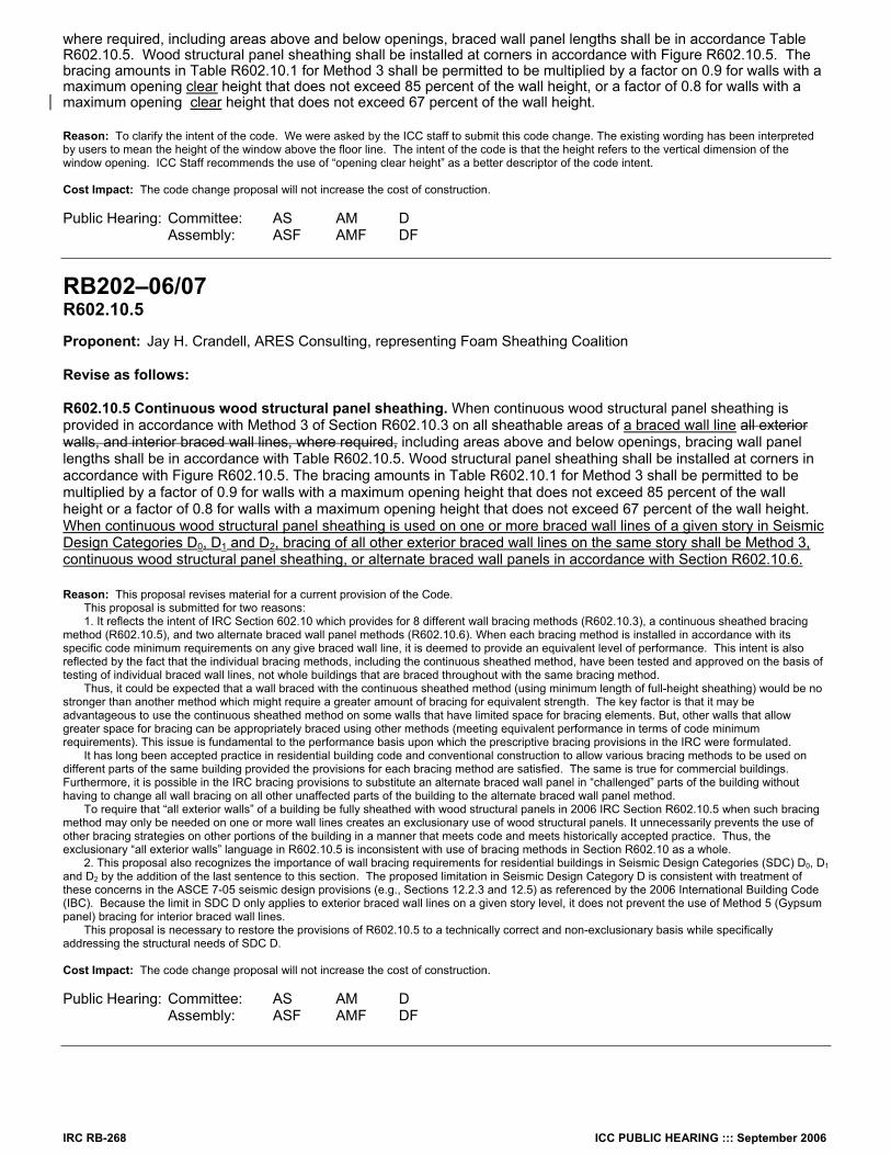
IRC RB-268 ICC PUBLIC HEARING ::: September 2006
where required, including areas above and below openings, braced wall panel lengths shall be in accordance Table R602.10.5. Wood structural panel sheathing shall be installed at corners in accordance with Figure R602.10.5. The bracing amounts in Table R602.10.1 for Method 3 shall be permitted to be multiplied by a factor on 0.9 for walls with a maximum opening clear height that does not exceed 85 percent of the wall height, or a factor of 0.8 for walls with a maximum opening clear height that does not exceed 67 percent of the wall height. Reason: To clarify the intent of the code. We were asked by the ICC staff to submit this code change. The existing wording has been interpreted by users to mean the height of the window above the floor line. The intent of the code is that the height refers to the vertical dimension of the window opening. ICC Staff recommends the use of “opening clear height” as a better descriptor of the code intent. Cost Impact: The code change proposal will not increase the cost of construction. Public Hearing: Committee: AS AM D Assembly: ASF AMF DF
RB202–06/07 R602.10.5 Proponent: Jay H. Crandell, ARES Consulting, representing Foam Sheathing Coalition Revise as follows: R602.10.5 Continuous wood structural panel sheathing. When continuous wood structural panel sheathing is provided in accordance with Method 3 of Section R602.10.3 on all sheathable areas of a braced wall line all exterior walls, and interior braced wall lines, where required, including areas above and below openings, bracing wall panel lengths shall be in accordance with Table R602.10.5. Wood structural panel sheathing shall be installed at corners in accordance with Figure R602.10.5. The bracing amounts in Table R602.10.1 for Method 3 shall be permitted to be multiplied by a factor of 0.9 for walls with a maximum opening height that does not exceed 85 percent of the wall height or a factor of 0.8 for walls with a maximum opening height that does not exceed 67 percent of the wall height. When continuous wood structural panel sheathing is used on one or more braced wall lines of a given story in Seismic Design Categories D0, D1 and D2, bracing of all other exterior braced wall lines on the same story shall be Method 3, continuous wood structural panel sheathing, or alternate braced wall panels in accordance with Section R602.10.6. Reason: This proposal revises material for a current provision of the Code. This proposal is submitted for two reasons: 1. It reflects the intent of IRC Section 602.10 which provides for 8 different wall bracing methods (R602.10.3), a continuous sheathed bracing method (R602.10.5), and two alternate braced wall panel methods (R602.10.6). When each bracing method is installed in accordance with its specific code minimum requirements on any give braced wall line, it is deemed to provide an equivalent level of performance. This intent is also reflected by the fact that the individual bracing methods, including the continuous sheathed method, have been tested and approved on the basis of testing of individual braced wall lines, not whole buildings that are braced throughout with the same bracing method. Thus, it could be expected that a wall braced with the continuous sheathed method (using minimum length of full-height sheathing) would be no stronger than another method which might require a greater amount of bracing for equivalent strength. The key factor is that it may be advantageous to use the continuous sheathed method on some walls that have limited space for bracing elements. But, other walls that allow greater space for bracing can be appropriately braced using other methods (meeting equivalent performance in terms of code minimum requirements). This issue is fundamental to the performance basis upon which the prescriptive bracing provisions in the IRC were formulated. It has long been accepted practice in residential building code and conventional construction to allow various bracing methods to be used on different parts of the same building provided the provisions for each bracing method are satisfied. The same is true for commercial buildings. Furthermore, it is possible in the IRC bracing provisions to substitute an alternate braced wall panel in “challenged” parts of the building without having to change all wall bracing on all other unaffected parts of the building to the alternate braced wall panel method. To require that “all exterior walls” of a building be fully sheathed with wood structural panels in 2006 IRC Section R602.10.5 when such bracing method may only be needed on one or more wall lines creates an exclusionary use of wood structural panels. It unnecessarily prevents the use of other bracing strategies on other portions of the building in a manner that meets code and meets historically accepted practice. Thus, the exclusionary “all exterior walls” language in R602.10.5 is inconsistent with use of bracing methods in Section R602.10 as a whole. 2. This proposal also recognizes the importance of wall bracing requirements for residential buildings in Seismic Design Categories (SDC) D0, D1 and D2 by the addition of the last sentence to this section. The proposed limitation in Seismic Design Category D is consistent with treatment of these concerns in the ASCE 7-05 seismic design provisions (e.g., Sections 12.2.3 and 12.5) as referenced by the 2006 International Building Code (IBC). Because the limit in SDC D only applies to exterior braced wall lines on a given story level, it does not prevent the use of Method 5 (Gypsum panel) bracing for interior braced wall lines. This proposal is necessary to restore the provisions of R602.10.5 to a technically correct and non-exclusionary basis while specifically addressing the structural needs of SDC D. Cost Impact: The code change proposal will not increase the cost of construction. Public Hearing: Committee: AS AM D Assembly: ASF AMF DF
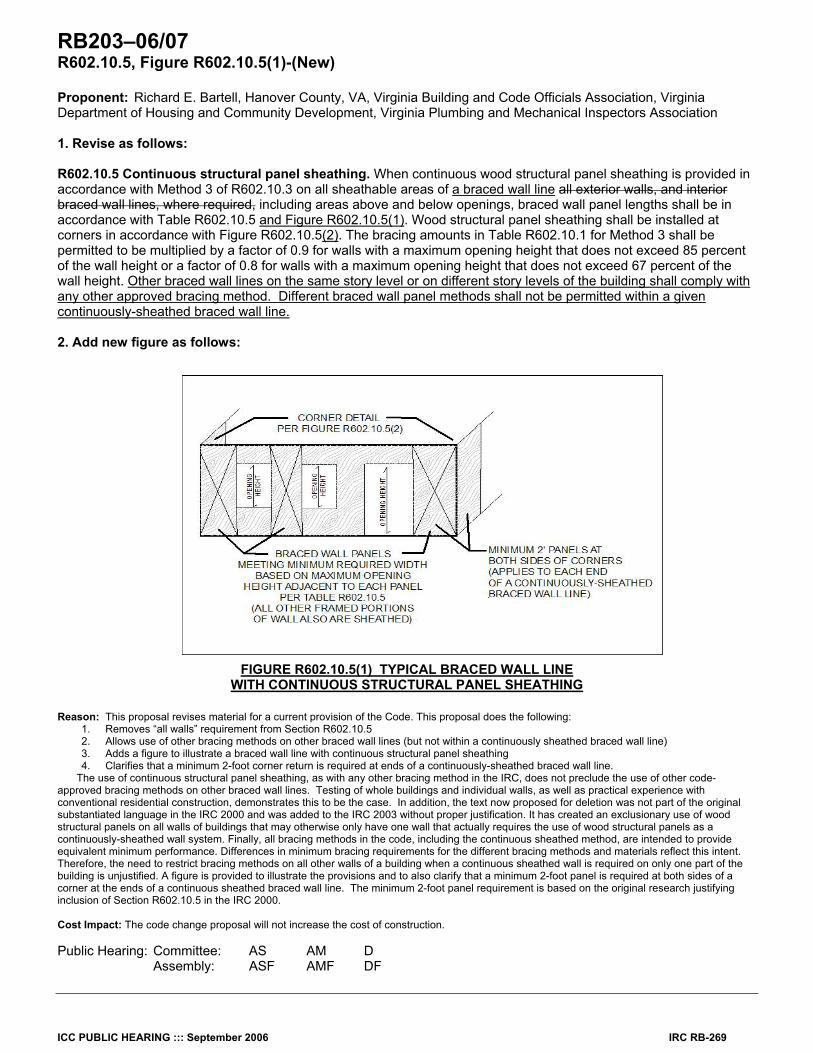
ICC PUBLIC HEARING ::: September 2006 IRC RB-269
RB203–06/07 R602.10.5, Figure R602.10.5(1)-(New) Proponent: Richard E. Bartell, Hanover County, VA, Virginia Building and Code Officials Association, Virginia Department of Housing and Community Development, Virginia Plumbing and Mechanical Inspectors Association 1. Revise as follows: R602.10.5 Continuous structural panel sheathing. When continuous wood structural panel sheathing is provided in accordance with Method 3 of R602.10.3 on all sheathable areas of a braced wall line all exterior walls, and interior braced wall lines, where required, including areas above and below openings, braced wall panel lengths shall be in accordance with Table R602.10.5 and Figure R602.10.5(1). Wood structural panel sheathing shall be installed at corners in accordance with Figure R602.10.5(2). The bracing amounts in Table R602.10.1 for Method 3 shall be permitted to be multiplied by a factor of 0.9 for walls with a maximum opening height that does not exceed 85 percent of the wall height or a factor of 0.8 for walls with a maximum opening height that does not exceed 67 percent of the wall height. Other braced wall lines on the same story level or on different story levels of the building shall comply with any other approved bracing method. Different braced wall panel methods shall not be permitted within a given continuously-sheathed braced wall line. 2. Add new figure as follows:
FIGURE R602.10.5(1) TYPICAL BRACED WALL LINE WITH CONTINUOUS STRUCTURAL PANEL SHEATHING
Reason: This proposal revises material for a current provision of the Code. This proposal does the following:
1. Removes “all walls” requirement from Section R602.10.5 2. Allows use of other bracing methods on other braced wall lines (but not within a continuously sheathed braced wall line) 3. Adds a figure to illustrate a braced wall line with continuous structural panel sheathing 4. Clarifies that a minimum 2-foot corner return is required at ends of a continuously-sheathed braced wall line.
The use of continuous structural panel sheathing, as with any other bracing method in the IRC, does not preclude the use of other code-approved bracing methods on other braced wall lines. Testing of whole buildings and individual walls, as well as practical experience with conventional residential construction, demonstrates this to be the case. In addition, the text now proposed for deletion was not part of the original substantiated language in the IRC 2000 and was added to the IRC 2003 without proper justification. It has created an exclusionary use of wood structural panels on all walls of buildings that may otherwise only have one wall that actually requires the use of wood structural panels as a continuously-sheathed wall system. Finally, all bracing methods in the code, including the continuous sheathed method, are intended to provide equivalent minimum performance. Differences in minimum bracing requirements for the different bracing methods and materials reflect this intent. Therefore, the need to restrict bracing methods on all other walls of a building when a continuous sheathed wall is required on only one part of the building is unjustified. A figure is provided to illustrate the provisions and to also clarify that a minimum 2-foot panel is required at both sides of a corner at the ends of a continuous sheathed braced wall line. The minimum 2-foot panel requirement is based on the original research justifying inclusion of Section R602.10.5 in the IRC 2000. Cost Impact: The code change proposal will not increase the cost of construction. Public Hearing: Committee: AS AM D Assembly: ASF AMF DF