Embed Size (px)
Citation preview

Structural Qualification Testing of the WindSatPayload Using Sine Bursts Near Structural
Resonance
Jim PontiusDonald Barnes
17 May 2001 GSFC FEMCI 2001 22
Outline
• Introduction• Objectives• Analytical approach• Experimental approach• Testing• Conclusions

17 May 2001 GSFC FEMCI 2001 33
Introduction
• WindSat Payload:• ~700 lb, 10.5’ GR/EP, Ti, and Al radiometer, 6’ reflector• Spins ~ 30 rpm, canister frame w/preloaded deck & launch locks for deployed
clearance• Acceleration gradient nearly 4:1 up the stack• Due to size & lightweight composite bonded reflector support structure construction,
static pull testing to qualify all composites and bonded joints in the upper structurewould result in large, expensive, and extensive test fixturing.
• Typical sine burst testing• Driving frequency vs. first resonant mode• Common scenario for large structures (and WindSat):
• Qualification of lower parts of the structure only, or• Over- test of lower structure to achieve qualification of upper structure• Using larger mass sims result in exceeding shaker displacement limitations

17 May 2001 GSFC FEMCI 2001 44
Introduction
• Sine burst testing near the first two structural resonant modes wasperformed on the WindSat payload to achieve the correct load factordistribution up the stack for structural qualification.
• This presentation discusses how FEM sine burst predictions wereused in conjunction with low level random and sine burst tests toachieve correct qualification test load factor distributions on theWindSat payload.
• Also presented is the risk mitigation approach for using theuncorrelated FEM in this procedure.

17 May 2001 GSFC FEMCI 2001 55
Objectives
• Qualify WindSat critical structural elements with near-resonancesine burst testing
• Proof load composite elements and bonded joints in WindSatstructure
• Prove rotating to stationary deployed structural clearances do notchange after dynamic load application
• Complete testing quickly and inexpensively

17 May 2001 GSFC FEMCI 2001 66
Analytical Approach
• Determine critical components by checking M.S. with no-test factors of safety• Screens out non-composite structure that can be qualified by analysis
• Analytically simulate the sine burst test (uncorrelated FEM)• Track accelerations at center of reflector and feed bench upper deck• Recover internal loads in critical components and compare with critical DLL• Estimate test parameters (frequency, input acceleration and direction) to qualify
critical components by tracking ratio of reflector-to-feed bench acceleration• NASTRAN FEM created using FEMAP
• ~22,000 nodes, ~110,000 DOFs, standard element types• Transient analyses completed on Craig-Bampton model using FLAME
• 1g X & Y input in 1Hz increments, 5 cycle ramps, 5 cycle hold• Plot responses and pick frequency that gives desired accelerations
• fanalytical input x = 21 Hz (f2 = 31.3 Hz), areflector = 12.0 g, Rx = 1.83• fanalytical input y = 18 Hz (f1 = 24.3 Hz), areflector = 17.8 g, Ry = 2.31

17 May 2001 GSFC FEMCI 2001 77
Analytical Approach

17 May 2001 GSFC FEMCI 2001 88
Analytical Approach

17 May 2001 GSFC FEMCI 2001 99
X-dir Sine Burst TRFs
-2.00
0.002.00
4.00
6.00
8.0010.00
12.00
14.00
16.0018.00
20.00
14 18 22 26 30
Freq (Hz)
Ao
ut/
Ain
Refl Gx
Refl Gy
Refl Gz
Feed Gx
Feed Gy
Feed Gz
Analytical Approach

17 May 2001 GSFC FEMCI 2001 1010
Analytical Approach

17 May 2001 GSFC FEMCI 2001 1111
Y-dir Sine Burst TRFs
-5.00
0.00
5.00
10.00
15.00
20.00
25.00
30.00
14 18 22 26 30
Freq (Hz)
Ao
ut/
Ain
Refl Gx
Refl Gy
Refl Gz
Feed Gx
Feed Gy
Feed Gz
Analytical Approach

17 May 2001 GSFC FEMCI 2001 1212
Experimental Approach
• Perform modal survey of WindSat in test configuration• Quick comparison of analytic vs. test frequencies
• Develop MATLAB script to track internal loads from strain readingsand write M.S. using the same analytical expressions used duringthe design phase• Uses time consistent data
• Perform shaker test to 150% of full analytically-predicted test levelswithout WindSat on the table
• Run X-dir qualification test first, then Y (Y-dir a bit more exciting!)• Generate pre-test low level random signature (1.0 Grms)

17 May 2001 GSFC FEMCI 2001 1313
Experimental Approach
• Use low level random FRFs to find Qs at the center of the reflectorand feed bench upper deck, and subsequently determine sine burstinput frequency and level• Calculate ratio of reflector-to-feed bench acceleration for various frequencies• Compare analytical and test ratios at analytically-predicted frequency and
modify input parameters accordingly
• Perform low level sine burst tests at -18 dB, -10dB, and -6 dB• Monitor M.S., compare actual internal loads with analytically-predicted values,
track linearity• Determine reflector-to-feed bench accel ratio and verify it remains constant• Extrapolate next load increase and full level accels• Make full level M.S. predicts via MATLAB script

17 May 2001 GSFC FEMCI 2001 1414
Experimental Approach
• Shift input frequency up or down to get correct ratio of reflector tofeed bench acceleration if needed
• Repeat low level sine bursts until “zero-ed” in on input frequency• Perform next level sine burst test, -3 dB
• Monitor M.S., compare actual internal loads with analytically-predicted values,track linearity
• Verify ratio doesn’t change at higher input levels• Extrapolate to next load increase, then compare with test• Make full level M.S. predicts via MATLAB script• Modify full level input as required to get 100% +/- 3% TLL
• Increase to -1 dB, repeat checks, then to qualification level• Perform low level random and overlay with pre-test FRFs
17 May 2001 GSFC FEMCI 2001 1515
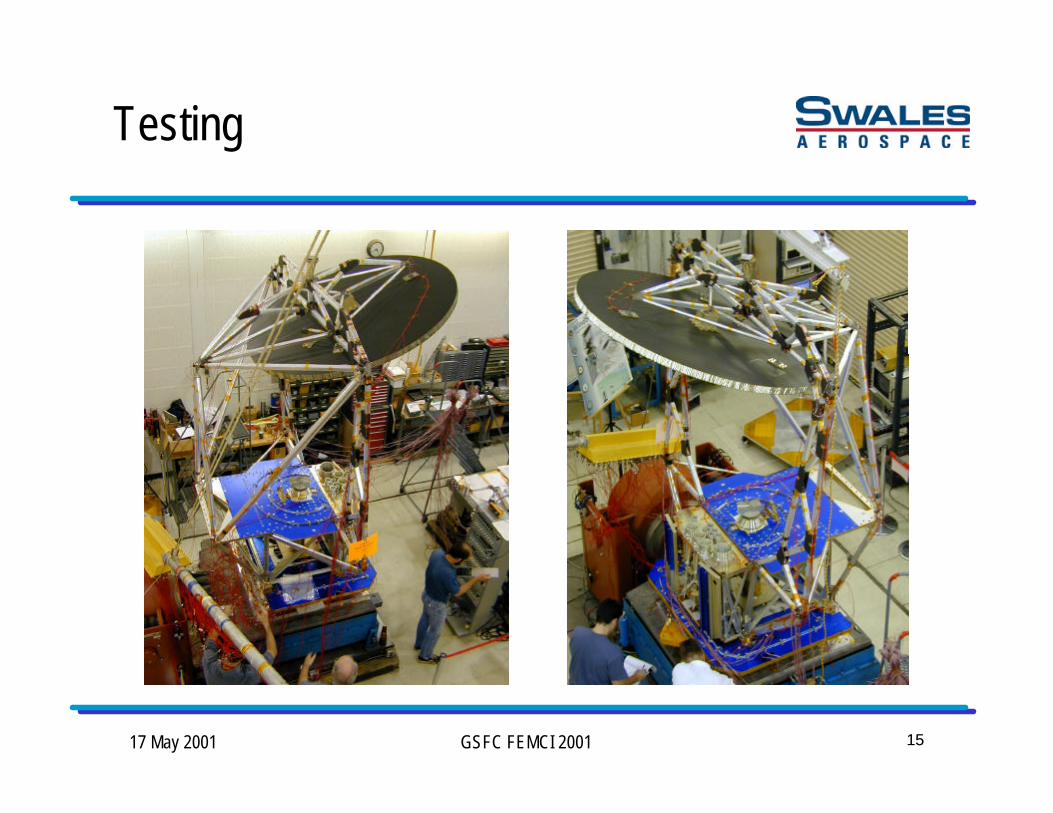
Testing

17 May 2001 GSFC FEMCI 2001 1616
Testing
• Instrumentation• 128 accel, 50 strain channels
• Performed modal survey• First 4 FEM modes were within 5% of test modes
• Quality, detailed model• Efficient structural design• Excellent manufacturing workmanship
• Performed low level random on slip table for X-dir• Reflector and feed bench FRFs from low level random were used to calculate
reflector to feed bench acceleration ratio and to compare with analytical ratio• No adjustment to initial sine burst frequency (21 Hz) made for X-dir test

17 May 2001 GSFC FEMCI 2001 1717
Testing
• Ran low level sine burst tests (-18 dB, -10 dB, and -6 dB) for X-dir• Verified system is responding linearly
• Acceleration ratio was constant (1.67, 1.60, 1.62)• Internal loads, moments increased linearly
• Verified no coupling/cross-talk• Monitored M.S. and made full level predictions• Both FEM predicts and low level random FRFs indicated that a 2 Hz increase
in input frequency was needed to get to accel ratio of 1.88 (goal was 1.83)
• Shifted sine burst test input frequency to 23 Hz for X-dir• Repeated -10 dB and -6 dB tests• New acceleration ratio was constant (1.90, 1.88)

17 May 2001 GSFC FEMCI 2001 1818
Testing
• Performed next level sine burst tests, -3 dB and -1 dB• Monitored M.S., compared actual internal loads with analytically-predicted
values, tracked linearity• Verified ratio didn’t change (R= 1.86)• Extrapolated next load increase, then compared with test• Made full level M.S. predictions via MATLAB script
• Determined qualification level would be reached at -0.5 dB• Performed qualification level sine burst test at -0.5 dB
1.9012.466.5623.0Test
1.8312.006.5621.0FEM
Accel RatioReflectoraccel (g’s)
Feed benchaccel (g’s)
Frequency(Hz)

17 May 2001 GSFC FEMCI 2001 1919
Testing
• Ran post-test low level random for X-dir• Compared pre- and post- test FRF overlays for frequency shifts
• Virtually identical• Reviewed all accelerometer channels
• Successful qualification for X-dir
• Performed low level random on slip table for Y-dir• Reflector and feed bench FRFs from low level random were used to calculate
reflector to feed bench acceleration ratio and to compare with analytical ratio• 2 Hz increase (from 18 Hz to 20 Hz) made to initial frequency for Y-dir test
• FEM showed R = 2.31 at 18 Hz• Test showed R = 2.38 at 20 Hz

17 May 2001 GSFC FEMCI 2001 2020
Testing
• Ran low level sine burst tests (-18 dB, -10 dB, and -6 dB) for Y-dir• Verified system is responding linearly
• Acceleration ratio was constant (2.61, 2.59, 2.60)• Internal loads, moments increased linearly
• Verified no coupling/cross-talk• Monitored M.S. and made full level predictions• Both FEM predicts and low level random FRFs indicated that a 1 Hz decrease
in input frequency was needed to get to accel ratio of ~2.25 (goal was 2.31)
• Shifted sine burst test input frequency to 19 Hz for Y-dir• Repeated -10 dB and -6 dB tests• New acceleration ratio was constant (2.27, 2.27)

17 May 2001 GSFC FEMCI 2001 2121
Testing
• Performed next level sine burst tests, -3 dB and -1 dB• Monitored M.S., compared actual internal loads with analytically-predicted
values, tracked linearity• Verified ratio didn’t change (R= 2.28)• Extrapolated next load increase, then compared with test• Made full level M.S. predictions via MATLAB script
• Determined qualification level would be reached at -0.5 dB• Performed qualification level sine burst test at -0.5 dB
2.2817.507.6819.0Test
2.3117.807.6918.0FEM
Accel RatioReflectoraccel (g’s)
Feed benchaccel (g’s)
Frequency(Hz)

17 May 2001 GSFC FEMCI 2001 2222
Testing
• Ran post-test low level random for Y-dir• Compared pre- and post- test FRF overlays for frequency shifts
• Virtually identical• Reviewed all accelerometer channels
• Successful qualification for Y-dir
• Deployed rotating canister launch locks• Measured clearances between stationary and deployed halves of launch locks• Gaps changed less than 0.001” (0.100” nominal)
• Successful qualification of WindSat structure

17 May 2001 GSFC FEMCI 2001 2323
Testing

17 May 2001 GSFC FEMCI 2001 2424
Testing

17 May 2001 GSFC FEMCI 2001 2525
Testing

17 May 2001 GSFC FEMCI 2001 2626
Testing

17 May 2001 GSFC FEMCI 2001 2727
Testing

17 May 2001 GSFC FEMCI 2001 2828
Testing

17 May 2001 GSFC FEMCI 2001 2929
Testing

17 May 2001 GSFC FEMCI 2001 3030
Testing

17 May 2001 GSFC FEMCI 2001 3131
Conclusions
• Successfully qualified WindSat structure• Achieved correct load factor distribution up the stack• No shifts in any frequencies• No change in performance of rotating/stationary structural deployment
• Finite element analytical simulation of sine burst test usedsuccessfully to prove test feasibility and reduce test time (frequencysearching)• Less risk if correlated FEM is available (program schedule issue)
• “Real time” assessment of sine burst test is invaluable (M.S., internalloads, full level predictions)
• Total time on shaker table was five (5) days (6/19/00 – 6/23/00)