Embed Size (px)
Citation preview
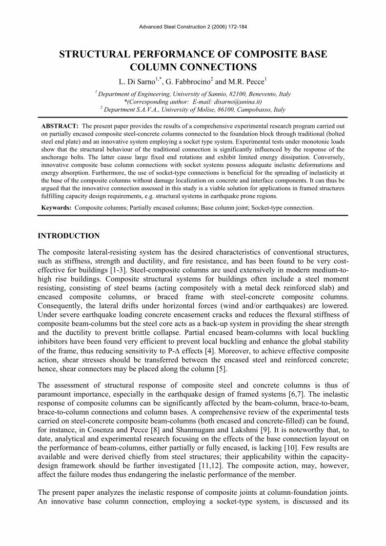
Advanced Steel Construction 2 (2006) 172-184
STRUCTURAL PERFORMANCE OF COMPOSITE BASE COLUMN CONNECTIONS
L. Di Sarno1,*, G. Fabbrocino2 and M.R. Pecce1
1 Department of Engineering, University of Sannio, 82100, Benevento, Italy *(Corresponding author: E-mail: [email protected])
2 Department S.A.V.A., University of Molise, 86100, Campobasso, Italy
ABSTRACT: The present paper provides the results of a comprehensive experimental research program carried out on partially encased composite steel-concrete columns connected to the foundation block through traditional (bolted steel end plate) and an innovative system employing a socket type system. Experimental tests under monotonic loads show that the structural behaviour of the traditional connection is significantly influenced by the response of the anchorage bolts. The latter cause large fixed end rotations and exhibit limited energy dissipation. Conversely, innovative composite base column connections with socket systems possess adequate inelastic deformations and energy absorption. Furthermore, the use of socket-type connections is beneficial for the spreading of inelasticity at the base of the composite columns without damage localization on concrete and interface components. It can thus be argued that the innovative connection assessed in this study is a viable solution for applications in framed structures fulfilling capacity design requirements, e.g. structural systems in earthquake prone regions.
Keywords: Composite columns; Partially encased columns; Base column joint; Socket-type connection.
INTRODUCTION
The composite lateral-resisting system has the desired characteristics of conventional structures, such as stiffness, strength and ductility, and fire resistance, and has been found to be very cost-effective for buildings [1-3]. Steel-composite columns are used extensively in modern medium-to-high rise buildings. Composite structural systems for buildings often include a steel moment resisting, consisting of steel beams (acting compositely with a metal deck reinforced slab) and encased composite columns, or braced frame with steel-concrete composite columns. Consequently, the lateral drifts under horizontal forces (wind and/or earthquakes) are lowered. Under severe earthquake loading concrete encasement cracks and reduces the flexural stiffness of composite beam-columns but the steel core acts as a back-up system in providing the shear strength and the ductility to prevent brittle collapse. Partial encased beam-columns with local buckling inhibitors have been found very efficient to prevent local buckling and enhance the global stability of the frame, thus reducing sensitivity to P- effects [4]. Moreover, to achieve effective composite action, shear stresses should be transferred between the encased steel and reinforced concrete; hence, shear connectors may be placed along the column [5].
The assessment of structural response of composite steel and concrete columns is thus of paramount importance, especially in the earthquake design of framed systems [6,7]. The inelastic response of composite columns can be significantly affected by the beam-column, brace-to-beam, brace-to-column connections and column bases. A comprehensive review of the experimental tests carried on steel-concrete composite beam-columns (both encased and concrete-filled) can be found, for instance, in Cosenza and Pecce [8] and Shanmugam and Lakshmi [9]. It is noteworthy that, to date, analytical and experimental research focusing on the effects of the base connection layout on the performance of beam-columns, either partially or fully encased, is lacking [10]. Few results are available and were derived chiefly from steel structures; their applicability within the capacity-design framework should be further investigated [11,12]. The composite action, may, however, affect the failure modes thus endangering the inelastic performance of the member.
The present paper analyzes the inelastic response of composite joints at column-foundation joints. An innovative base column connection, employing a socket-type system, is discussed and its
Structural Performance of Composite Base Column Connections 173
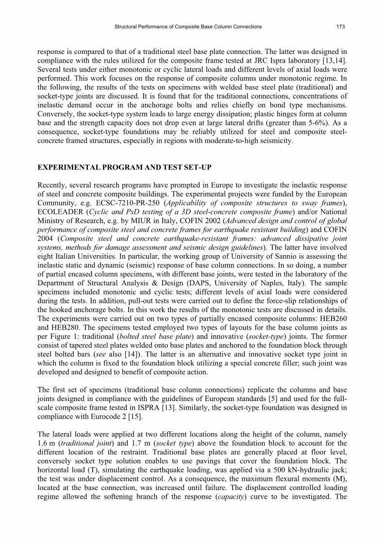
response is compared to that of a traditional steel base plate connection. The latter was designed in compliance with the rules utilized for the composite frame tested at JRC Ispra laboratory [13,14]. Several tests under either monotonic or cyclic lateral loads and different levels of axial loads were performed. This work focuses on the response of composite columns under monotonic regime. In the following, the results of the tests on specimens with welded base steel plate (traditional) and socket-type joints are discussed. It is found that for the traditional connections, concentrations of inelastic demand occur in the anchorage bolts and relies chiefly on bond type mechanisms. Conversely, the socket-type system leads to large energy dissipation; plastic hinges form at column base and the strength capacity does not drop even at large lateral drifts (greater than 5-6%). As a consequence, socket-type foundations may be reliably utilized for steel and composite steel-concrete framed structures, especially in regions with moderate-to-high seismicity.
EXPERIMENTAL PROGRAM AND TEST SET-UP
Recently, several research programs have prompted in Europe to investigate the inelastic response of steel and concrete composite buildings. The experimental projects were funded by the European Community, e.g. ECSC-7210-PR-250 (Applicability of composite structures to sway frames),ECOLEADER (Cyclic and PsD testing of a 3D steel-concrete composite frame) and/or National Ministry of Research, e.g. by MIUR in Italy, COFIN 2002 (Advanced design and control of global performance of composite steel and concrete frames for earthquake resistant building) and COFIN 2004 (Composite steel and concrete earthquake-resistant frames: advanced dissipative joint systems, methods for damage assessment and seismic design guidelines). The latter have involved eight Italian Universities. In particular, the working group of University of Sannio is assessing the inelastic static and dynamic (seismic) response of base column connections. In so doing, a number of partial encased column specimens, with different base joints, were tested in the laboratory of the Department of Structural Analysis & Design (DAPS, University of Naples, Italy). The sample specimens included monotonic and cyclic tests; different levels of axial loads were considered during the tests. In addition, pull-out tests were carried out to define the force-slip relationships of the hooked anchorage bolts. In this work the results of the monotonic tests are discussed in details. The experiments were carried out on two types of partially encased composite columns: HEB260 and HEB280. The specimens tested employed two types of layouts for the base column joints as per Figure 1: traditional (bolted steel base plate) and innovative (socket-type) joints. The former consist of tapered steel plates welded onto base plates and anchored to the foundation block through steel bolted bars (see also [14]). The latter is an alternative and innovative socket type joint in which the column is fixed to the foundation block utilizing a special concrete filler; such joint was developed and designed to benefit of composite action.
The first set of specimens (traditional base column connections) replicate the columns and base joints designed in compliance with the guidelines of European standards [5] and used for the full-scale composite frame tested in ISPRA [13]. Similarly, the socket-type foundation was designed in compliance with Eurocode 2 [15].
The lateral loads were applied at two different locations along the height of the column, namely 1.6 m (traditional joint) and 1.7 m (socket type) above the foundation block to account for the different location of the restraint. Traditional base plates are generally placed at floor level, conversely socket type solution enables to use pavings that cover the foundation block. The horizontal load (T), simulating the earthquake loading, was applied via a 500 kN-hydraulic jack; the test was under displacement control. As a consequence, the maximum flexural moments (M), located at the base connection, was increased until failure. The displacement controlled loading regime allowed the softening branch of the response (capacity) curve to be investigated. The
174 L. Di Sarno et al.
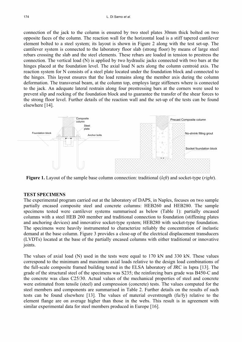
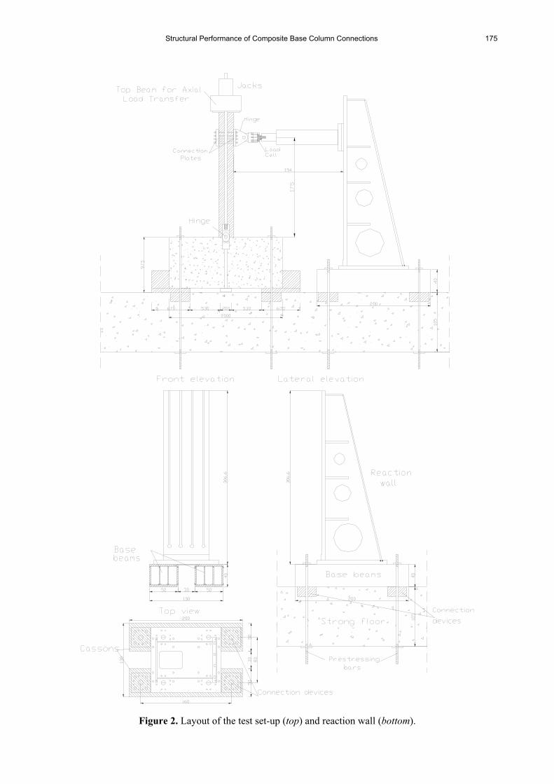
connection of the jack to the column is ensured by two steel plates 30mm thick bolted on two opposite faces of the column. The reaction wall for the horizontal load is a stiff tapered cantilever element bolted to a steel system; its layout is shown in Figure 2 along with the test set-up. The cantilever system is connected to the laboratory floor slab (strong floor) by means of large steel rebars crossing the slab and the steel elements. These rebars are loaded in tension to prestress the connection. The vertical load (N) is applied by two hydraulic jacks connected with two bars at the hinges placed at the foundation level. The axial load N acts along the column centroid axis. The reaction system for N consists of a steel plate located under the foundation block and connected to the hinges. This layout ensures that the load remains along the member axis during the column deformation. The transversal beam, at the column top, employs large stiffeners where is connected to the jack. An adequate lateral restrain along four prestressing bars at the corners were used to prevent slip and rocking of the foundation block and to guarantee the transfer of the shear forces to the strong floor level. Further details of the reaction wall and the set-up of the tests can be found elsewhere [14].
Composite column
Foundation blockAnchor bolts
Steel plate
Precast Composite column
Socket foundation block
No-shrink filling grout
Figure 1. Layout of the sample base column connection: traditional (left) and socket-type (right).
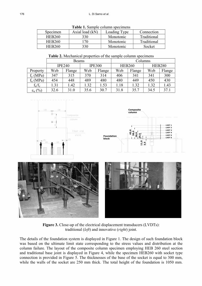
TEST SPECIMENS The experimental program carried out at the laboratory of DAPS, in Naples, focuses on two sample partially encased composite steel and concrete columns: HEB260 and HEB280. The sample specimens tested were cantilever systems summarised as below (Table 1): partially encased columns with a steel HEB 260 member and traditional connection to foundation (stiffening plates and anchoring devices) and innovative socket-type system; HEB280 with socket-type foundation. The specimens were heavily instrumented to characterize reliably the concentration of inelastic demand at the base column. Figure 3 provides a close-up of the electrical displacement transducers (LVDTs) located at the base of the partially encased columns with either traditional or innovative joints.
The values of axial load (N) used in the tests were equal to 170 kN and 330 kN. These values correspond to the minimum and maximum axial loads relative to the design load combinations of the full-scale composite framed building tested in the ELSA laboratory of JRC in Ispra [13]. The grade of the structural steel of the specimens was S235; the reinforcing bars grade was B450-C and the concrete was class C25/30. Actual values of the mechanical properties of steel and concrete were estimated from tensile (steel) and compression (concrete) tests. The values computed for the steel members and components are summarised in Table 2. Further details on the results of such tests can be found elsewhere [13]. The values of material overstrength (fu/fy) relative to the element flange are on average higher than those in the webs. This result is in agreement with similar experimental data for steel members produced in Europe [16].
Structural Performance of Composite Base Column Connections 175
Figure 2. Layout of the test set-up (top) and reaction wall (bottom).
176 L. Di Sarno et al.
Table 1. Sample column specimens Specimen Axial load (kN) Loading Type Connection HEB260 330 Monotonic Traditional HEB260 170 Monotonic Traditional HEB260 330 Monotonic Socket
Table 2. Mechanical properties of the sample column specimens Beams Columns IPE240 IPE300 HEB260 HEB280
Property Web Flange Web Flange Web Flange Web Flange fy (MPa) 347 315 370 314 406 341 341 300 fu (MPa) 454 448 489 480 480 449 450 430
fu/fy 1.31 1.42 1.32 1.53 1.18 1.32 1.32 1.43 u (%) 32.6 31.0 35.6 30.7 31.8 35.7 34.5 37.1
38
,04
5,0
28
,0
20
,51
1,0
3,5
LVDT 4
LVDT 6LVDT 5
LVDT 3
LVDT 2
LVDT 1
Compositecolumn
blockFoundation
Figure 3. Close-up of the electrical displacement transducers (LVDTs): traditional (left) and innovative (right) joint.
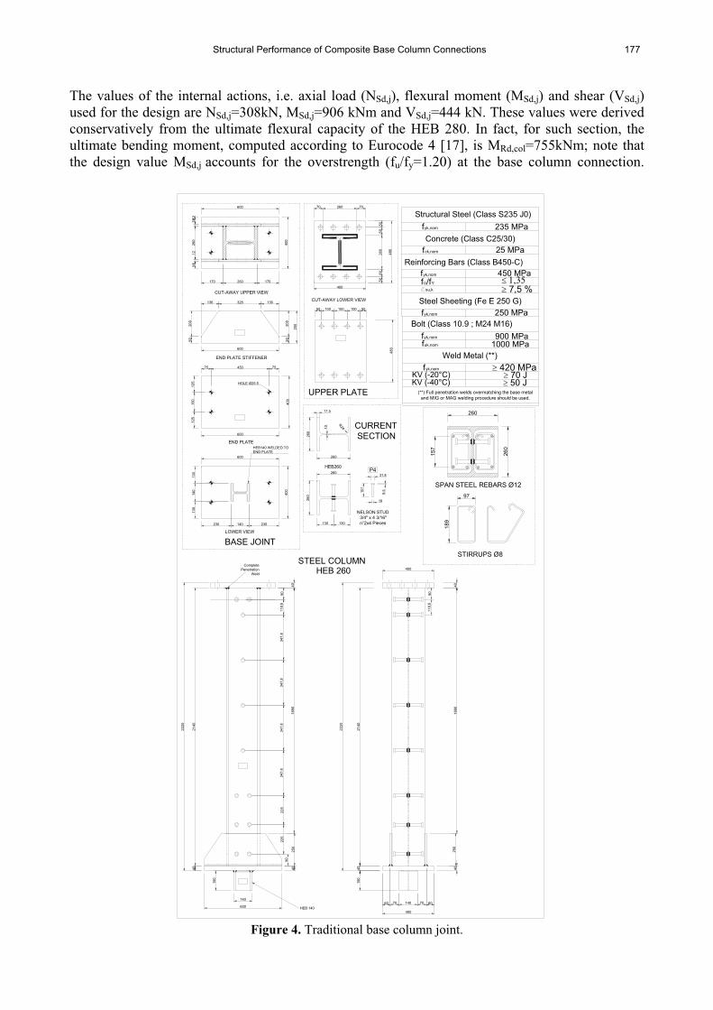
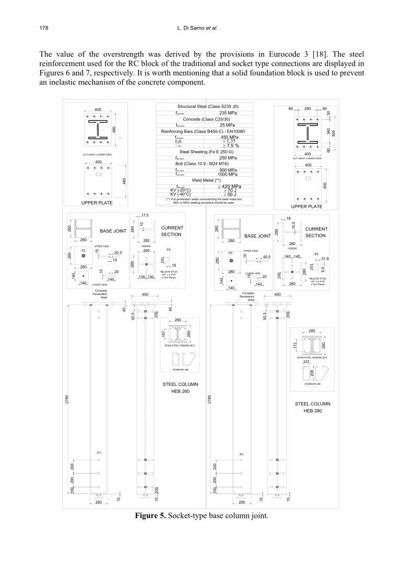
The details of the foundation system is displayed in Figure 1. The design of such foundation block was based on the ultimate limit state corresponding to the stress values and distribution at the column failure. The layout of the composite column specimen employing HEB 260 steel section and traditional base joint is displayed in Figure 4, while the specimen HEB260 with socket type connection is provided in Figure 5. The thicknesses of the base of the socket is equal to 300 mm, while the walls of the socket are 250 mm thick. The total height of the foundation is 1050 mm.
Structural Performance of Composite Base Column Connections 177
The values of the internal actions, i.e. axial load (NSd,j), flexural moment (MSd,j) and shear (VSd,j)used for the design are NSd,j=308kN, MSd,j=906 kNm and VSd,j=444 kN. These values were derived conservatively from the ultimate flexural capacity of the HEB 280. In fact, for such section, the ultimate bending moment, computed according to Eurocode 4 [17], is MRd,col=755kNm; note that the design value MSd,j accounts for the overstrength (fu/fy=1.20) at the base column connection.
HEB 260
UPPER PLATE
STEEL COLUMN
CURRENT
260
17.5
260
2220
75 450 75
125
150
125
600
400
600
5020
0
5020
0
136 328 136
600
130
140
130
230 140 230
400
250
END PLATE STIFFENER
END PLATE
LOWER VIEW
HEB140 WELDED TOEND PLATE
BASE JOINT
600
5812
260
1258
170 260 17040
0
CUT-AWAY UPPER VIEW
HOLE Ø25.5
347,
8
2220
2140
1890
140
600
150
40
90
250
40
225
225
HEB 140
347,
834
7,8
347,
811
8,6
90
CompletePenetration
Weld
40
2140
1890
140
400
4015
0
7060
402 5
0
6070
400
118,
690
40
260
130130
R24
260
10
HEB260 P4
NELSON STUD 3/4" x 4 3/16"n°2x4 Pieces
19
31.8
101
9.5
SPAN STEEL REBARS Ø12
189
157
260
STIRRUPS Ø8
97
260
Reinforcing Bars (Class B450-C)
Steel Sheeting (Fe E 250 G)fyk,nom
fU/fYsu,k
fyk,nom
250 MPa
7,5 %
450 MPa
Structural Steel (Class S235 J0)
Concrete (Class C25/30)fyk,nom
fck,nom
235 MPa
25 MPa
KV (-20°C) 70 J
(**) Full penetration welds overmatching the base metal and MIG or MAG welding procedure should be used.
KV (-40°C) 50 J
Bolt (Class 10.9 ; M24 M16)
Weld Metal (**)
fyk,nom
fyk,nom
fuk,nom
900 MPa
420 MPa
1000 MPa
7070
CUT-AWAY LOWER VIEW
100
400
10050 50100
480
5050
60
480
6026
0
260
SECTION
Figure 4. Traditional base column joint.
178 L. Di Sarno et al.
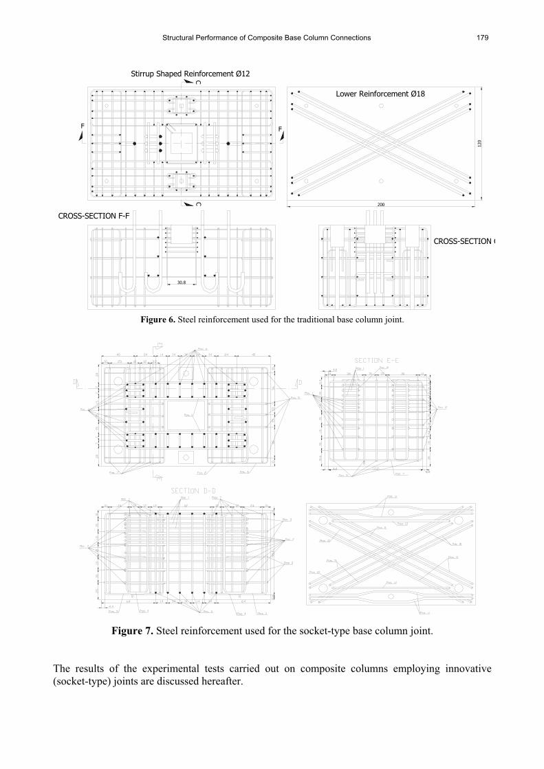
The value of the overstrength was derived by the provisions in Eurocode 3 [18]. The steel reinforcement used for the RC block of the traditional and socket type connections are displayed in Figures 6 and 7, respectively. It is worth mentioning that a solid foundation block is used to prevent an inelastic mechanism of the concrete component.
260
HEB260
260
260
17.5
10
BASE JOINTCURRENT
19
101
NELSON STUD 3/4" x 4 3/16"n°2x4 Pieces130 130
260
260
2785
40 40
STEEL COLUMN
LOWER VIEW
260
260
140
140 20
20.5
10
15
140
15
260
260
UPPER VIEW280
280 10
.5
18
HEB280
140 140
28010
0 2 80
31.8
9.510
1
NELSON STUD 3/4" x 4 3/16"n°2x4 Pieces
280
2785
LOWER VIEW280
280
140
140 20
40.5
15
140
15280
280
UPPER VIEW
92.5 100
15 1510
0
P1
P2 P4
400
CompletePenetration
Weld
5050
0
400
UPPER PLATE
500
60 60
60
CUT-AWAY LOWER VIEW
92.5 100
1 5 15
P1
P2 P4
200
200
100
200
200
100
UPPER PLATE
480
CUT-AWAY LOWER VIEW
CompletePenetration
Weld400
STIRRUPS Ø8
107
208
280
280
172
260
260
157
STIRRUPS Ø8
Reinforcing Bars (Class B450-C) - EN10080
Steel Sheeting (Fe E 250 G)fyk,nom
fU/fYsu,k
fyk,nom
250 MPa
7,5 %
450 MPa
Structural Steel (Class S235 J0)
Concrete (Class C25/30)fyk,nom
fck,nom
235 MPa
25 MPa
KV (-20°C) 70 J
(**) Full penetration welds overmatching the base metal and MIG or MAG welding procedure should be used.
KV (-40°C) 50 J
Bolt (Class 10.9 ; M24 M16)
Weld Metal (**)
fyk,nom
fyk,nom
fuk,nom
900 MPa
420 MPa
1000 MPa
SPAN STEEL REBARS Ø12
SPAN STEEL REBARS Ø12
SECTION
HEB 260
CURRENTSECTIONBASE JOINT
STEEL COLUMN HEB 280
400
480
400 280
340
400
Figure 5. Socket-type base column joint.
Structural Performance of Composite Base Column Connections 179
200
F
30.8
CC
F
120
Stirrup Shaped Reinforcement Ø12
Lower Reinforcement Ø18
CROSS-SECTION C
CROSS-SECTION F-F
Figure 6. Steel reinforcement used for the traditional base column joint.
Figure 7. Steel reinforcement used for the socket-type base column joint.
The results of the experimental tests carried out on composite columns employing innovative (socket-type) joints are discussed hereafter.
180 L. Di Sarno et al.
TEST RESULTS
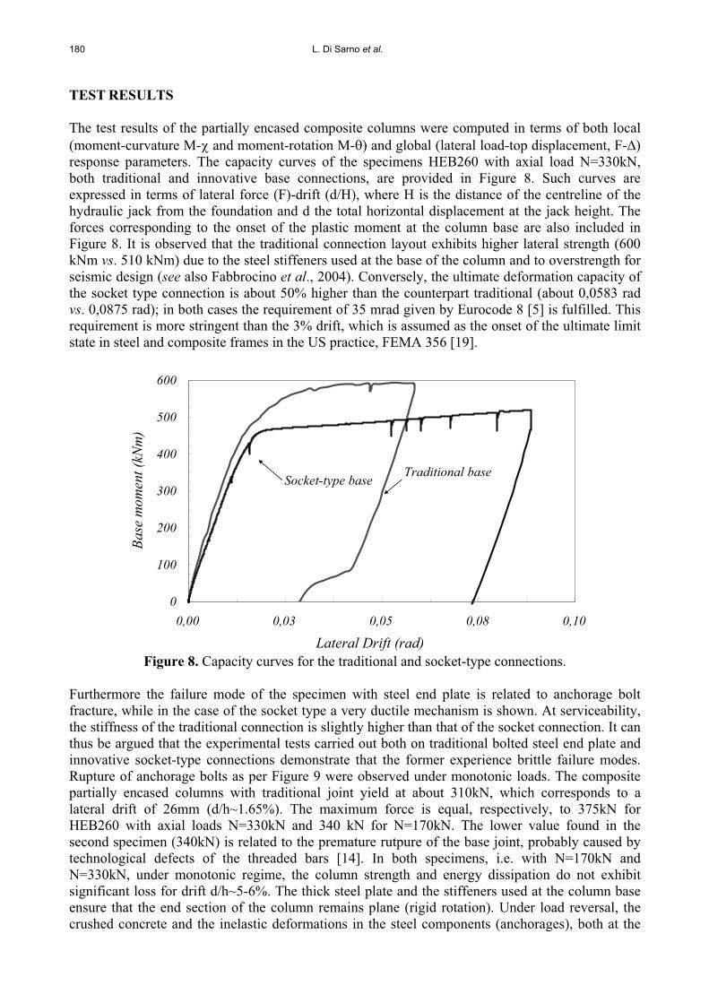
The test results of the partially encased composite columns were computed in terms of both local (moment-curvature M- and moment-rotation M- ) and global (lateral load-top displacement, F- )response parameters. The capacity curves of the specimens HEB260 with axial load N=330kN, both traditional and innovative base connections, are provided in Figure 8. Such curves are expressed in terms of lateral force (F)-drift (d/H), where H is the distance of the centreline of the hydraulic jack from the foundation and d the total horizontal displacement at the jack height. The forces corresponding to the onset of the plastic moment at the column base are also included in Figure 8. It is observed that the traditional connection layout exhibits higher lateral strength (600 kNm vs. 510 kNm) due to the steel stiffeners used at the base of the column and to overstrength for seismic design (see also Fabbrocino et al., 2004). Conversely, the ultimate deformation capacity of the socket type connection is about 50% higher than the counterpart traditional (about 0,0583 rad vs. 0,0875 rad); in both cases the requirement of 35 mrad given by Eurocode 8 [5] is fulfilled. This requirement is more stringent than the 3% drift, which is assumed as the onset of the ultimate limit state in steel and composite frames in the US practice, FEMA 356 [19].
0
100
200
300
400
500
600
0,00 0,03 0,05 0,08 0,10
Lateral Drift (rad)
Base
mom
ent (
kNm
)
Traditional baseSocket-type base
Figure 8. Capacity curves for the traditional and socket-type connections.
Furthermore the failure mode of the specimen with steel end plate is related to anchorage bolt fracture, while in the case of the socket type a very ductile mechanism is shown. At serviceability, the stiffness of the traditional connection is slightly higher than that of the socket connection. It can thus be argued that the experimental tests carried out both on traditional bolted steel end plate and innovative socket-type connections demonstrate that the former experience brittle failure modes. Rupture of anchorage bolts as per Figure 9 were observed under monotonic loads. The composite partially encased columns with traditional joint yield at about 310kN, which corresponds to a lateral drift of 26mm (d/h~1.65%). The maximum force is equal, respectively, to 375kN for HEB260 with axial loads N=330kN and 340 kN for N=170kN. The lower value found in the second specimen (340kN) is related to the premature rutpure of the base joint, probably caused by technological defects of the threaded bars [14]. In both specimens, i.e. with N=170kN and N=330kN, under monotonic regime, the column strength and energy dissipation do not exhibit significant loss for drift d/h~5-6%. The thick steel plate and the stiffeners used at the column base ensure that the end section of the column remains plane (rigid rotation). Under load reversal, the crushed concrete and the inelastic deformations in the steel components (anchorages), both at the
Structural Performance of Composite Base Column Connections 181
column base, endanger the global lateral stiffness of the composite column. Bond-related phenomena give rise to degrading effects, especially at large drifts, thus reducing significantly the energy dissipation capacity of the member. These results point out that traditional connections are not fully satisfactory, especially when relevance of reinforced concrete component increases, i.e. due to cross section dimensions. Conversely, innovative socket-type connections possess adequate ductility. Under monotonic load conditions, the test results show strain hardening of the base column equal to 1.32. This is due chiefly to the material over-strength of structural steel (see values of fu/fy of the member flange in Table 2). The contribution of the hardening of the longitudinal reinforcement bars is in fact very small (1.13 vs. 1.32). The tests carried out on the specimens employing the socket joint do not exhibit strength deterioration even at large lateral drifts, e.g. d/h > 0.04-0.05 radians. The formation of the plastic hinge occurs at the base column, as observed during the tests.
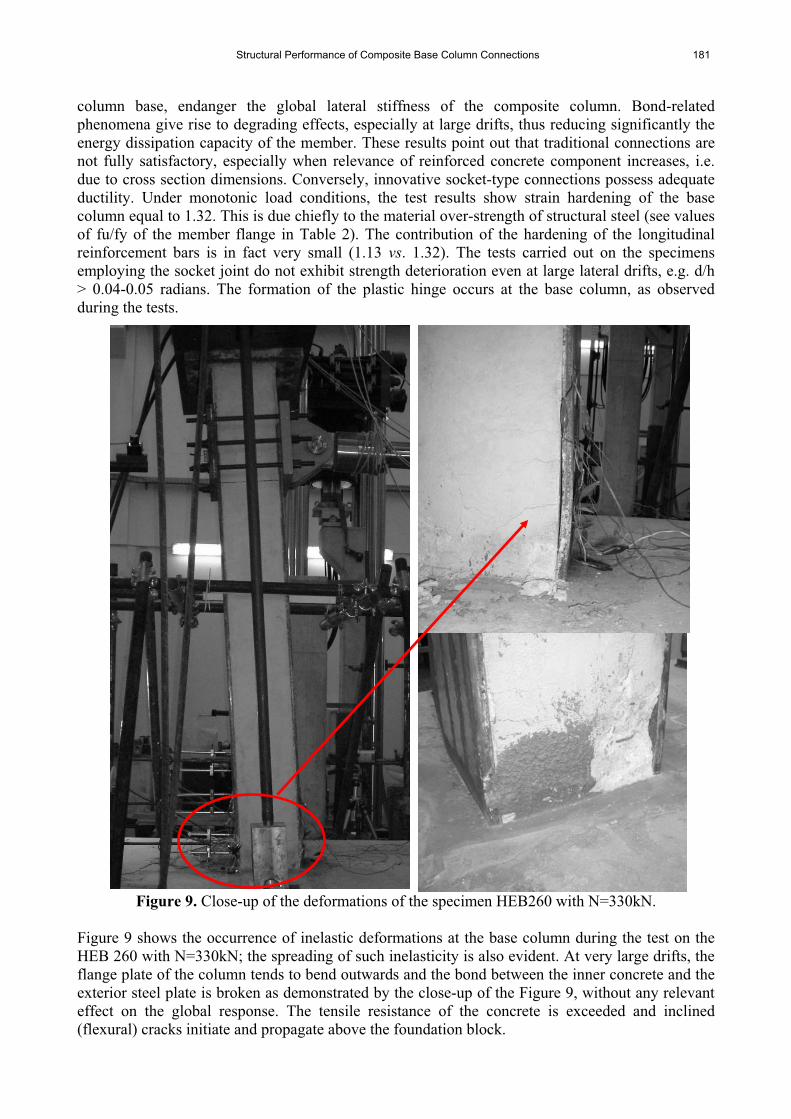
Figure 9. Close-up of the deformations of the specimen HEB260 with N=330kN.
Figure 9 shows the occurrence of inelastic deformations at the base column during the test on the HEB 260 with N=330kN; the spreading of such inelasticity is also evident. At very large drifts, the flange plate of the column tends to bend outwards and the bond between the inner concrete and the exterior steel plate is broken as demonstrated by the close-up of the Figure 9, without any relevant effect on the global response. The tensile resistance of the concrete is exceeded and inclined (flexural) cracks initiate and propagate above the foundation block.
182 L. Di Sarno et al.
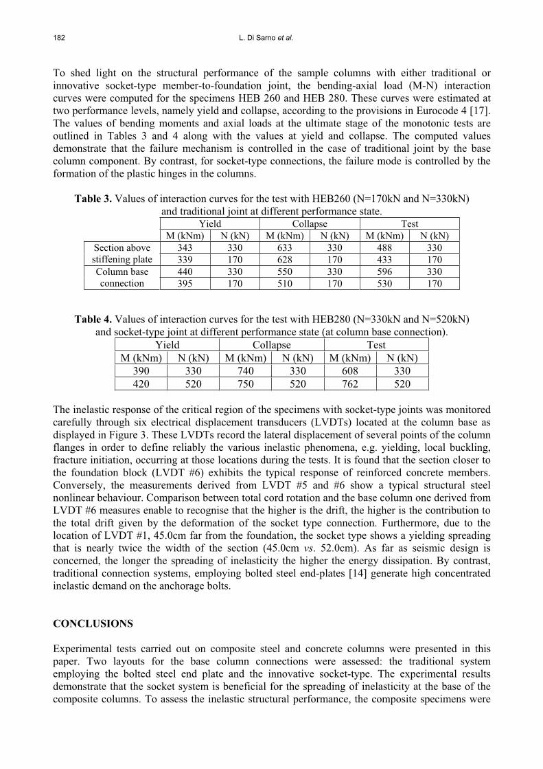
To shed light on the structural performance of the sample columns with either traditional or innovative socket-type member-to-foundation joint, the bending-axial load (M-N) interaction curves were computed for the specimens HEB 260 and HEB 280. These curves were estimated at two performance levels, namely yield and collapse, according to the provisions in Eurocode 4 [17]. The values of bending moments and axial loads at the ultimate stage of the monotonic tests are outlined in Tables 3 and 4 along with the values at yield and collapse. The computed values demonstrate that the failure mechanism is controlled in the case of traditional joint by the base column component. By contrast, for socket-type connections, the failure mode is controlled by the formation of the plastic hinges in the columns.
Table 3. Values of interaction curves for the test with HEB260 (N=170kN and N=330kN) and traditional joint at different performance state.
Yield Collapse Test M (kNm) N (kN) M (kNm) N (kN) M (kNm) N (kN)
343 330 633 330 488 330 Section above stiffening plate 339 170 628 170 433 170
440 330 550 330 596 330 Column base connection 395 170 510 170 530 170
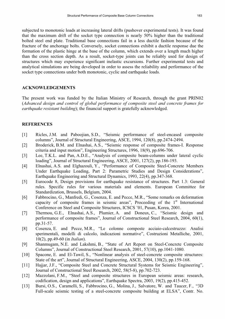
Table 4. Values of interaction curves for the test with HEB280 (N=330kN and N=520kN) and socket-type joint at different performance state (at column base connection).
Yield Collapse Test M (kNm) N (kN) M (kNm) N (kN) M (kNm) N (kN)
390 330 740 330 608 330 420 520 750 520 762 520
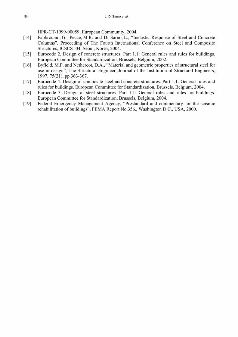
The inelastic response of the critical region of the specimens with socket-type joints was monitored carefully through six electrical displacement transducers (LVDTs) located at the column base as displayed in Figure 3. These LVDTs record the lateral displacement of several points of the column flanges in order to define reliably the various inelastic phenomena, e.g. yielding, local buckling, fracture initiation, occurring at those locations during the tests. It is found that the section closer to the foundation block (LVDT #6) exhibits the typical response of reinforced concrete members. Conversely, the measurements derived from LVDT #5 and #6 show a typical structural steel nonlinear behaviour. Comparison between total cord rotation and the base column one derived from LVDT #6 measures enable to recognise that the higher is the drift, the higher is the contribution to the total drift given by the deformation of the socket type connection. Furthermore, due to the location of LVDT #1, 45.0cm far from the foundation, the socket type shows a yielding spreading that is nearly twice the width of the section (45.0cm vs. 52.0cm). As far as seismic design is concerned, the longer the spreading of inelasticity the higher the energy dissipation. By contrast, traditional connection systems, employing bolted steel end-plates [14] generate high concentrated inelastic demand on the anchorage bolts.
CONCLUSIONS
Experimental tests carried out on composite steel and concrete columns were presented in this paper. Two layouts for the base column connections were assessed: the traditional system employing the bolted steel end plate and the innovative socket-type. The experimental results demonstrate that the socket system is beneficial for the spreading of inelasticity at the base of the composite columns. To assess the inelastic structural performance, the composite specimens were
Structural Performance of Composite Base Column Connections 183
subjected to monotonic loads at increasing lateral drifts (pushover experimental tests). It was found that the maximum drift of the socket type connection is nearly 50% higher than the traditional bolted steel end plate. Traditional base connections fail in a less ductile fashion because of the fracture of the anchorage bolts. Conversely, socket connections exhibit a ductile response due the formation of the plastic hinge at the base of the column, which extends over a length much higher than the cross section depth. As a result, socket-type joints can be reliably used for design of structures which may experience significant inelastic excursions. Further experimental tests and analytical simulations are being developed in order to assess the reliability and performance of the socket type connections under both monotonic, cyclic and earthquake loads.
ACKNOWLEDGEMENTS
The present work was funded by the Italian Ministry of Research, through the grant PRIN02 (Advanced design and control of global performance of composite steel and concrete frames for earthquake resistant building); the financial support is gratefully acknowledged.
REFERENCES
[1] Ricles, J.M. and Paboojian, S.D., “Seismic performance of steel-encased composite columns”, Journal of Structural Engineering, ASCE, 1994, 120(8), pp.2474-2494.
[2] Broderick, B.M. and Elnashai, A.S., “Seismic response of composite frames-I. Response criteria and input motion”, Engineering Structures, 1996, 18(9), pp.696-706.
[3] Lee, T.K.L. and Pan, A.D.E., “Analysis of composite beam-columns under lateral cyclic loading”, Journal of Structural Engineering, ASCE, 2001, 127(2), pp.186-193.
[4] Elnashai, A.S. and Elghazouli, Y., “Performance of Composite Steel-Concrete Members Under Earthquake Loading, Part 2: Parametric Studies and Design Considerations”, Earthquake Engineering and Structural Dynamics, 1993, 22(4), pp.347-368.
[5] Eurocode 8, Design provisions for earthquake resistance of structures. Part 1.3: General rules. Specific rules for various materials and elements. European Committee for Standardization, Brussels, Belgium, 2004.
[6] Fabbrocino, G., Manfredi, G., Cosenza, E. and Pecce, M.R., “Some remarks on deformation capacity of composite frames in seismic areas”, Proceeding of the 1st International Conference on Steel and Composite Structures, ICSCS ’01, Pusan, Korea, 2001.
[7] Thermou, G.E., Elnashai, A.S., Plumier, A. and Doneux, C., “Seismic design and performance of composite frames”, Journal of Constructional Steel Research, 2004, 60(1), pp.31-57.
[8] Cosenza, E. and Pecce, M.R., “Le colonne composte acciaio-calcestruzzo: Analisi sperimentali, modelli di calcolo, indicazioni normative”, Costruzioni Metalliche, 2001, 10(2), pp.49-60 (in Italian).
[9] Shanmugam, N.E. and Lakshmi, B., “State of Art Report on Steel-Concrete Composite Columns”, Journal of Constructional Steel Research, 2001, 57(10), pp.1041-1080.
[10] Spacone, E. and El-Tawil, S., “Nonlinear analysis of steel-concrete composite structures: State of the art”, Journal of Structural Engineering, ASCE, 2004, 130(2), pp.159-168.
[11] Hajjar, J.F., “Composite Steel and Concrete Structural Systems for Seismic Engineering”, Journal of Constructional Steel Research, 2002, 58(5-8), pp.702-723.
[12] Mazzolani, F.M., “Steel and composite structures in European seismic areas: research, codification, design and applications”, Earthquake Spectra, 2003, 19(2), pp.415-452.
[13] Bursi, O.S., Caramelli, S., Fabbrocino, G., Molina, J., Salvatore, W. and Taucer, F., “3D Full-scale seismic testing of a steel-concrete composite building at ELSA”, Contr. No.
184 L. Di Sarno et al.
HPR-CT-1999-00059, European Community, 2004. [14] Fabbrocino, G., Pecce, M.R. and Di Sarno, L., “Inelastic Response of Steel and Concrete
Columns”, Proceeding of The Fourth International Conference on Steel and Composite Structures, ICSCS ’04, Seoul, Korea, 2004.
[15] Eurocode 2, Design of concrete structures. Part 1.1: General rules and rules for buildings. European Committee for Standardization, Brussels, Belgium, 2002.
[16] Byfield, M.P. and Nethercot, D.A., “Material and geometric properties of structural steel for use in design”, The Structural Engineer, Journal of the Institution of Structural Engineers, 1997, 75(21), pp.363-367.
[17] Eurocode 4. Design of composite steel and concrete structures. Part 1.1: General rules and rules for buildings. European Committee for Standardization, Brussels, Belgium, 2004.
[18] Eurocode 3. Design of steel structures. Part 1.1: General rules and rules for buildings. European Committee for Standardization, Brussels, Belgium, 2004.
[19] Federal Emergency Management Agency, “Prestandard and commentary for the seismic rehabilitation of buildings”, FEMA Report No.356., Washington D.C., USA, 2000.