Embed Size (px)
Citation preview
International Research Journal of Engineering and Technology (IRJET) e-ISSN: 2395 -0056
Volume: 04 Issue: 06 | June -2017 www.irjet.net p-ISSN: 2395-0072
© 2017, IRJET | Impact Factor value: 5.181 | ISO 9001:2008 Certified Journal | Page 3171
A Comparative study of RC column and Composite column with flat slab
system using linear static analysis and Constructional sequential
analysis.
Arpitha Gowda S L1, Dr.Gopisiddappa2, Sindhoora C3
1M.Tec Student, Department of civil Engineering, PES college of Engineering Mandya, Karnataka, India 2HOD and Professor, Department of civil Engineering, PES college of Engineering Mandya, Karnataka, India 3M.Tec Student, Department of civil Engineering, AIT college of Engineering Chikmagalur, Karnataka, India
---------------------------------------------------------------------***---------------------------------------------------------------------
Abstract – Analysis of building is done in a single step using linear static analysis when the construction of the whole structure is completed by assuming that the structures are subjected to full loads. In reality the application the dead load due to the structural compound and finishing items are imposed stage by stage separately as the construction of the structure is constructed storey be storey in construction sequential analysis we consider all the load which are applied stage by stage which are neglected in general static analysis. The comparison is carried out between linear static analysis and constructional sequential analysis (CSA) to show that CSA is more accurate than linear static analysis. The analysis is done to conventional column and composite column in flat slab system , the differences and similarities are observed in different zones of India. The study is carried out using ETABS.
Key Words: composite column, conventional column, flat slab, ETABS, CSA
1. INTRODUCTION
Structural design is nothing but the combination of Art and Science, behavior of structure is the unspoken feeling of an Engineer with the acumen of knowledge. It may include the principle of statistic, dynamics, mechanics of materials, and structural analysis, to produce safe economic structure which is durable and serve the intended purpose
1.1 Construction Sequence Analysis (CSA)
Staged construction or sequential construction is defined as a sequence of stages which involve sadding or removing the portions of the structure, selectively applying a load to portions of the structure this type of construction is known as incremental construction, sequential construction or segmental construction
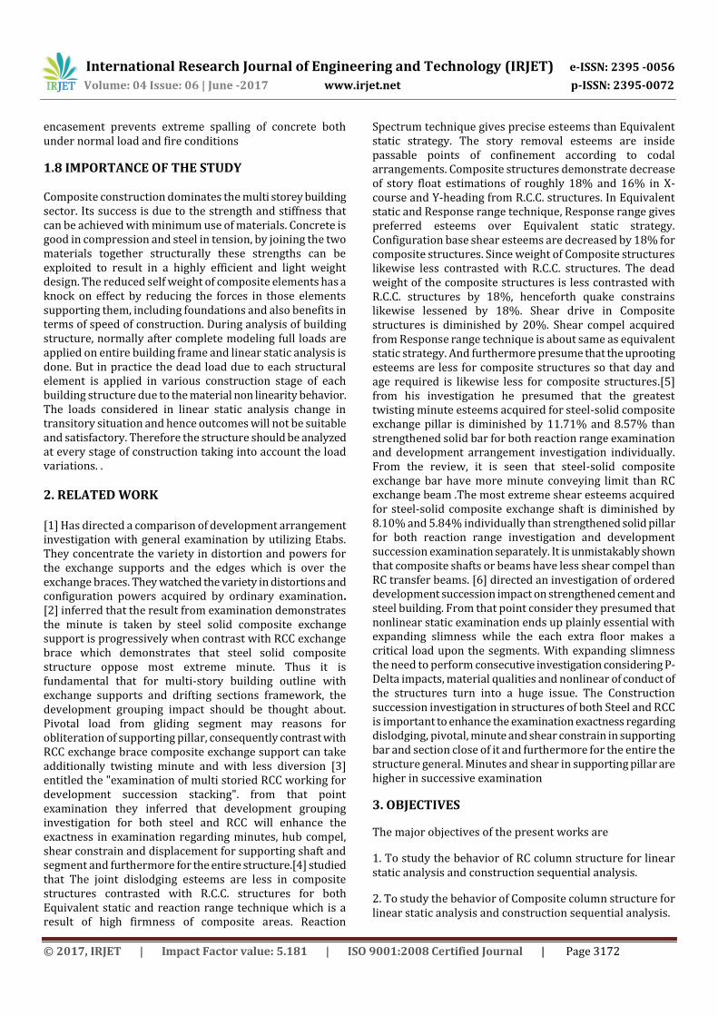
Figure-1: Conventional and staged construction
1.2 FLAT SLAB
In general normal RC frame construction consists of columns, slabs & beams. However it is possible to construction a high rise building without providing beams, in such a case the frame system will be consisting of slab and column without beams. These types of Slabs are called flat slab, flat slab resembles behavior of flat plates in bending
1.3STEEL-CONCRETE COMPOSITE COLUMN
A steel-concrete composite column is a compression member, comprising may either be of concrete encased hot-rolled steel section or a concrete filled tubular section of hot-rolled steel and is generally used as a load-bearing member in a composite framed structure. Typical cross-sections of composite columns with concrete encased and concrete
filled sections are illustrated in Fig2a and Fig 2b.
Figure:2
In a composite column both the steel and concrete would resist the external loading by interact together by bond and friction. Complementary reinforcement in the concrete
International Research Journal of Engineering and Technology (IRJET) e-ISSN: 2395 -0056
Volume: 04 Issue: 06 | June -2017 www.irjet.net p-ISSN: 2395-0072
© 2017, IRJET | Impact Factor value: 5.181 | ISO 9001:2008 Certified Journal | Page 3172
encasement prevents extreme spalling of concrete both under normal load and fire conditions
1.8 IMPORTANCE OF THE STUDY Composite construction dominates the multi storey building sector. Its success is due to the strength and stiffness that can be achieved with minimum use of materials. Concrete is good in compression and steel in tension, by joining the two materials together structurally these strengths can be exploited to result in a highly efficient and light weight design. The reduced self weight of composite elements has a knock on effect by reducing the forces in those elements supporting them, including foundations and also benefits in terms of speed of construction. During analysis of building structure, normally after complete modeling full loads are applied on entire building frame and linear static analysis is done. But in practice the dead load due to each structural element is applied in various construction stage of each building structure due to the material non linearity behavior. The loads considered in linear static analysis change in transitory situation and hence outcomes will not be suitable and satisfactory. Therefore the structure should be analyzed at every stage of construction taking into account the load variations. .
2. RELATED WORK [1] Has directed a comparison of development arrangement investigation with general examination by utilizing Etabs. They concentrate the variety in distortion and powers for the exchange supports and the edges which is over the exchange braces. They watched the variety in distortions and configuration powers acquired by ordinary examination. [2] inferred that the result from examination demonstrates the minute is taken by steel solid composite exchange support is progressively when contrast with RCC exchange brace which demonstrates that steel solid composite structure oppose most extreme minute. Thus it is fundamental that for multi-story building outline with exchange supports and drifting sections framework, the development grouping impact should be thought about. Pivotal load from gliding segment may reasons for obliteration of supporting pillar, consequently contrast with RCC exchange brace composite exchange support can take additionally twisting minute and with less diversion [3] entitled the "examination of multi storied RCC working for development succession stacking". from that point examination they inferred that development grouping investigation for both steel and RCC will enhance the exactness in examination regarding minutes, hub compel, shear constrain and displacement for supporting shaft and segment and furthermore for the entire structure.[4] studied that The joint dislodging esteems are less in composite structures contrasted with R.C.C. structures for both Equivalent static and reaction range technique which is a result of high firmness of composite areas. Reaction
Spectrum technique gives precise esteems than Equivalent static strategy. The story removal esteems are inside passable points of confinement according to codal arrangements. Composite structures demonstrate decrease of story float estimations of roughly 18% and 16% in X-course and Y-heading from R.C.C. structures. In Equivalent static and Response range technique, Response range gives preferred esteems over Equivalent static strategy. Configuration base shear esteems are decreased by 18% for composite structures. Since weight of Composite structures likewise less contrasted with R.C.C. structures. The dead weight of the composite structures is less contrasted with R.C.C. structures by 18%, henceforth quake constrains likewise lessened by 18%. Shear drive in Composite structures is diminished by 20%. Shear compel acquired from Response range technique is about same as equivalent static strategy. And furthermore presume that the uprooting esteems are less for composite structures so that day and age required is likewise less for composite structures.[5] from his investigation he presumed that the greatest twisting minute esteems acquired for steel-solid composite exchange pillar is diminished by 11.71% and 8.57% than strengthened solid bar for both reaction range examination and development arrangement investigation individually. From the review, it is seen that steel-solid composite exchange bar have more minute conveying limit than RC exchange beam .The most extreme shear esteems acquired for steel-solid composite exchange shaft is diminished by 8.10% and 5.84% individually than strengthened solid pillar for both reaction range investigation and development succession examination separately. It is unmistakably shown that composite shafts or beams have less shear compel than RC transfer beams. [6] directed an investigation of ordered development succession impact on strengthened cement and steel building. From that point consider they presumed that nonlinear static examination ends up plainly essential with expanding slimness while the each extra floor makes a critical load upon the segments. With expanding slimness the need to perform consecutive investigation considering P-Delta impacts, material qualities and nonlinear of conduct of the structures turn into a huge issue. The Construction succession investigation in structures of both Steel and RCC is important to enhance the examination exactness regarding dislodging, pivotal, minute and shear constrain in supporting bar and section close of it and furthermore for the entire the structure general. Minutes and shear in supporting pillar are higher in successive examination
3. OBJECTIVES
The major objectives of the present works are
1. To study the behavior of RC column structure for linear static analysis and construction sequential analysis.
2. To study the behavior of Composite column structure for linear static analysis and construction sequential analysis.

International Research Journal of Engineering and Technology (IRJET) e-ISSN: 2395 -0056
Volume: 04 Issue: 06 | June -2017 www.irjet.net p-ISSN: 2395-0072
© 2017, IRJET | Impact Factor value: 5.181 | ISO 9001:2008 Certified Journal | Page 3173
3. Comparative study of RC column structure and Composite column structure for linear static analysis and sequential analysis for different earthquake zones of India All analysis is carried out for flat slab system.
4. METHODOLOGY
Present analysis considers multi-storey reinforced concrete framed buildings and a composite building according to Architectural plan with storey heights of G+17 with 2 basements each having a storey height of 4 m where as 2 basement with ground floor having a story height of 4.5m. Buildings are comprised of ordinary moment resisting frames without brick infill for zone II and special RC moment resisting frame without brick infill for zone III,IV and V. Dimension of building elements were arrived on the basis of structural design following the respective Indian standard codes for design of reinforced concrete structures IS 456:2000. Details of different geometric parameters of building components are as shown in Tables below. The schematic representation of building plans are shown in fig 3.M60 grade concrete were used columns at lower level i.e. at basement and M25 grade concrete were used for slabs and Fe500 grade steel were selected as the materials for design of structural elements.
.
Figure-3: Architectural plan
Table-1:Building details
Table-2:Column details
International Research Journal of Engineering and Technology (IRJET) e-ISSN: 2395 -0056
Volume: 04 Issue: 06 | June -2017 www.irjet.net p-ISSN: 2395-0072
© 2017, IRJET | Impact Factor value: 5.181 | ISO 9001:2008 Certified Journal | Page 3174
Table-3: Slab details
Size in mm Type Grade
S125 Shell thin M25
S150 Shell thin M25
S200 Shell thin M25
S250 Shell thin M25
S275 Shell thin M25
S290 Shell thin M25
S450 Shell thin M25
S475 Shell thin M25
S500 Shell thin M25
S550 Shell thin M25
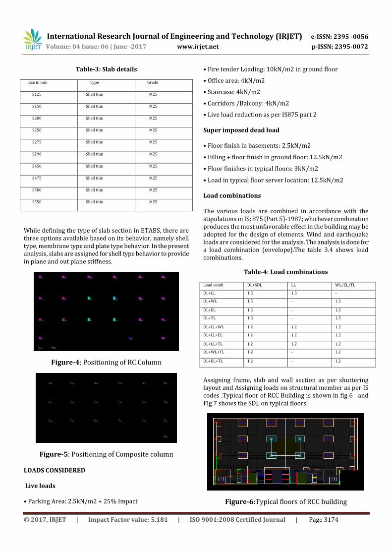
While defining the type of slab section in ETABS, there are three options available based on its behavior, namely shell type, membrane type and plate type behavior. In the present analysis, slabs are assigned for shell type behavior to provide in plane and out plane stiffness.
Figure-4: Positioning of RC Column
Figure-5: Positioning of Composite column
LOADS CONSIDERED Live loads • Parking Area: 2.5kN/m2 + 25% Impact
• Fire tender Loading: 10kN/m2 in ground floor
• Office area: 4kN/m2
• Staircase: 4kN/m2
• Corridors /Balcony: 4kN/m2
• Live load reduction as per IS875 part 2 Super imposed dead load • Floor finish in basements: 2.5kN/m2
• Filling + floor finish in ground floor: 12.5kN/m2
• Floor finishes in typical floors: 3kN/m2
• Load in typical floor server location: 12.5kN/m2 Load combinations The various loads are combined in accordance with the stipulations in IS: 875 (Part 5)-1987; whichever combination produces the most unfavorable effect in the building may be adopted for the design of elements. Wind and earthquake loads are considered for the analysis. The analysis is done for a load combination (envelope).The table 3.4 shows load combinations.
Table-4: Load combinations
Load comb DL+SDL LL WL/EL/TL
DL+LL 1.5 1.5 -
DL+WL 1.5 - 1.5
DL+EL 1.5 - 1.5
DL+TL 1.5 - 1.5
DL+LL+WL 1.2 1.2 1.2
DL+LL+EL 1.2 1.2 1.2
DL+LL+TL 1.2 1.2 1.2
DL+WL+TL 1.2 - 1.2
DL+EL+TL 1.2 - 1.2
Assigning frame, slab and wall section as per shuttering layout and Assigning loads on structural member as per IS codes .Typical floor of RCC Building is shown in fig 6 and Fig 7 shows the SDL on typical floors
Figure-6:Typical floors of RCC building
International Research Journal of Engineering and Technology (IRJET) e-ISSN: 2395 -0056
Volume: 04 Issue: 06 | June -2017 www.irjet.net p-ISSN: 2395-0072
© 2017, IRJET | Impact Factor value: 5.181 | ISO 9001:2008 Certified Journal | Page 3175
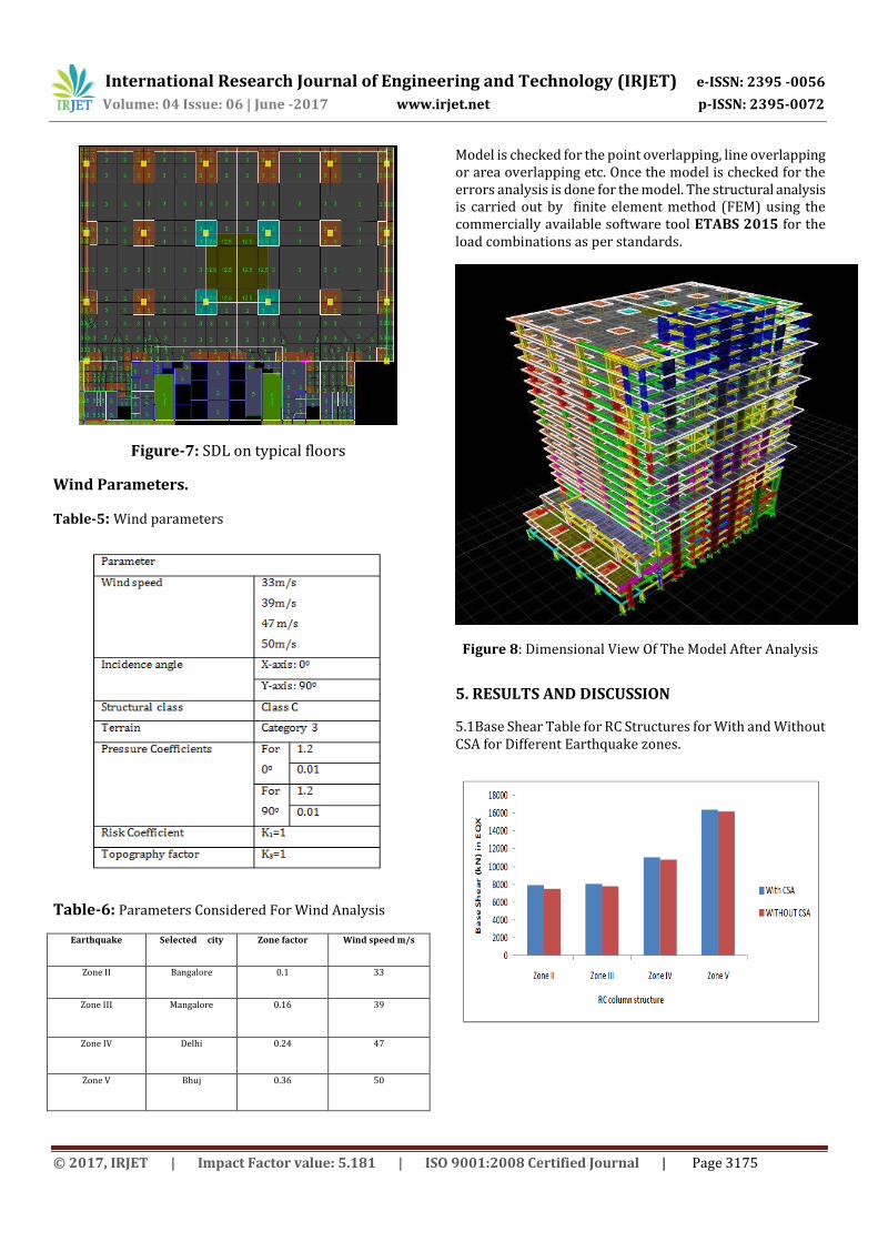
Figure-7: SDL on typical floors
Wind Parameters.
Table-5: Wind parameters
Table-6: Parameters Considered For Wind Analysis
Earthquake Selected city Zone factor Wind speed m/s
Zone II Bangalore 0.1 33
Zone III Mangalore 0.16 39
Zone IV Delhi 0.24 47
Zone V Bhuj 0.36 50
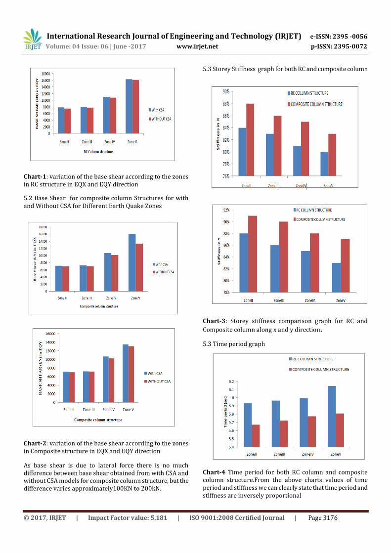
Model is checked for the point overlapping, line overlapping or area overlapping etc. Once the model is checked for the errors analysis is done for the model. The structural analysis is carried out by finite element method (FEM) using the commercially available software tool ETABS 2015 for the load combinations as per standards.
Figure 8: Dimensional View Of The Model After Analysis
5. RESULTS AND DISCUSSION
5.1Base Shear Table for RC Structures for With and Without CSA for Different Earthquake zones.
International Research Journal of Engineering and Technology (IRJET) e-ISSN: 2395 -0056
Volume: 04 Issue: 06 | June -2017 www.irjet.net p-ISSN: 2395-0072
© 2017, IRJET | Impact Factor value: 5.181 | ISO 9001:2008 Certified Journal | Page 3176
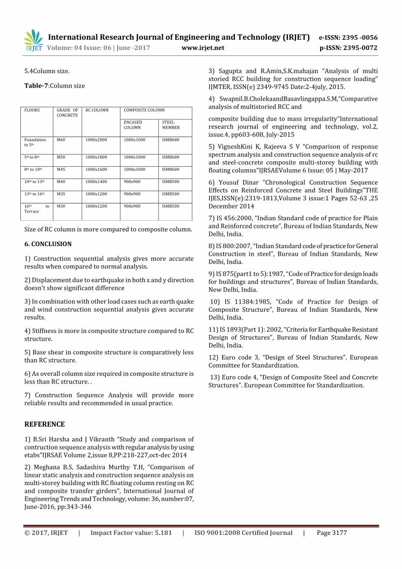
Chart-1: variation of the base shear according to the zones in RC structure in EQX and EQY direction
5.2 Base Shear for composite column Structures for with and Without CSA for Different Earth Quake Zones
Chart-2: variation of the base shear according to the zones in Composite structure in EQX and EQY direction
As base shear is due to lateral force there is no much difference between base shear obtained from with CSA and without CSA models for composite column structure, but the difference varies approximately100KN to 200kN.
5.3 Storey Stiffness graph for both RC and composite column
Chart-3: Storey stiffness comparison graph for RC and
Composite column along x and y direction.
5.3 Time period graph
Chart-4 Time period for both RC column and composite column structure.From the above charts values of time period and stiffness we can clearly state that time period and stiffness are inversely proportional
International Research Journal of Engineering and Technology (IRJET) e-ISSN: 2395 -0056
Volume: 04 Issue: 06 | June -2017 www.irjet.net p-ISSN: 2395-0072
© 2017, IRJET | Impact Factor value: 5.181 | ISO 9001:2008 Certified Journal | Page 3177
5.4Column size.
Table-7:Column size
Size of RC column is more compared to composite column.
6. CONCLUSION
1) Construction sequential analysis gives more accurate results when compared to normal analysis.
2) Displacement due to earthquake in both x and y direction doesn’t show significant difference
3) In combination with other load cases such as earth quake and wind construction sequential analysis gives accurate results.
4) Stiffness is more in composite structure compared to RC structure.
5) Base shear in composite structure is comparatively less than RC structure.
6) As overall column size required in composite structure is less than RC structure. .
7) Construction Sequence Analysis will provide more reliable results and recommended in usual practice.
REFERENCE
1) B.Sri Harsha and J Vikranth “Study and comparison of contruction sequence analysis with regular analysis by using etabs”IJRSAE Volume 2,issue 8,PP:218-227,oct-dec 2014
2) Meghana B.S, Sadashiva Murthy T.H, “Comparison of linear static analysis and construction sequence analysis on multi-storey building with RC floating column resting on RC and composite transfer girders”, International Journal of Engineering Trends and Technology, volume: 36, number:07, June-2016, pp:343-346
3) Sagupta and R.Amin,S.K.mahajan “Analysis of multi storied RCC building for construction sequence loading” IJMTER, ISSN(e) 2349-9745 Date:2-4july, 2015.
4) Swapnil.B.CholekaandBasavlingappa.S.M,“Comparative analysis of multistoried RCC and
composite building due to mass irregularity”International research journal of engineering and technology, vol.2, issue.4, pp603-608, July-2015
5) VigneshKini K, Rajeeva S V “Comparison of response spectrum analysis and construction sequence analysis of rc and steel-concrete composite multi-storey building with floating columns”IJRSAEVolume 6 Issue: 05 | May-2017
6) Yousuf Dinar “Chronological Construction Sequence Effects on Reinforced Concrete and Steel Buildings”THE IJES,ISSN(e):2319-1813,Volume 3 issue:1 Pages 52-63 ,25 December 2014
7) IS 456:2000, “Indian Standard code of practice for Plain and Reinforced concrete”, Bureau of Indian Standards, New Delhi, India.
8) IS 800:2007, “Indian Standard code of practice for General Construction in steel”, Bureau of Indian Standards, New Delhi, India.
9) IS 875(part1 to 5):1987, “Code of Practice for design loads for buildings and structures”, Bureau of Indian Standards, New Delhi, India.
10) IS 11384:1985, “Code of Practice for Design of Composite Structure”, Bureau of Indian Standards, New Delhi, India.
11) IS 1893(Part 1): 2002, “Criteria for Earthquake Resistant Design of Structures”, Bureau of Indian Standards, New Delhi, India.
12) Euro code 3, “Design of Steel Structures”. European Committee for Standardization.
13) Euro code 4, “Design of Composite Steel and Concrete Structures”. European Committee for Standardization.
FLOORS GRADE OF CONCRETE
RC COLUMN COMPOSITE COLUMN
ENCASED COLUMN
STEEL MEMBER
Foundation to 5th
M60 1000x2000 1000x1000 ISMB600
5th to 8th M50 1000x1800 1000x1000 ISMB600
8th to 10th M45 1000x1600 1000x1000 ISMB600
10th to 13th M40 1000x1400 900x900 ISMB500
13th to 16th M35 1000x1200 900x900 ISMB500
16th to Terrace
M30 1000x1200 900x900 ISMB500