Embed Size (px)
Citation preview
Geosynthetics 2015 February 15-18, Portland, Oregon
1/10
Structural Pavement Design with Geocells made of Novel Polymeric Alloy
Ofer Kief, Ph.D., Yenon Research & Design Ltd, Israel, [email protected] ABSTRACT Although the use of geocells in geotechnical applications dates back to the early 1980's, two major drawbacks prevented their widespread adoption in structural pavements: 1) The ability to maintain structural stability for the pavement design life, and 2) A lack of integration into the Mechanistic-Empirical Structural Pavement Design method. In recent years much research and many comprehensive field tests were conducted on geocell technology. One result of these studies was the development of a novel polymeric alloy (NPA), which significantly decreases large strains associated with HDPE-based geocells that prevented their implementation in flexible pavements below the asphaltic layer. Two major innovative mechanisms are associated with NPA geocells: 1) Beam Effect – the ability to create a semi-rigid platform as a result of the confinement of unbound granular material, and 2) Significant vertical stress reduction to the under-laying layers. By overcoming drawbacks in the basic technology, implementation of geocells in the upper structural pavement layer is now feasible. 1. INTRODUCTION Despite four decades of use in the base layer of unbound roads, cellular confinement systems, or geocells, have not been widely used in structural pavements due to two major drawbacks:
a. Questions about the geocell long-term service life and dimensional stability of the geocell in structural pavements. b. Lack of a well-developed methodology integrating the geocell confinement mechanism into the existing
Mechanistic-Empirical - Structural Pavement Design (Han et el 2008, Yuu et al 2008). In recent years many comprehensive studies and research work have been conducted on geocells worldwide (Iowa State University, University of Kansas, Indian Institutes of Technology, Clausthal University - Germany, KOAC-NPC – Netherlands (Kief et al 2014). This research has broadened our understanding of geocells and their reinforcement mechanisms. As part of these efforts, an innovative novel polymer alloy (NPA) was developed to create stiffer geocells, leading to a measurable improvement in performance. One such parameter is a significant decrease in anticipated large strains during the service period, which is associated with HDPE-based geocells. By overcoming this stumbling block implementation of geocells in the upper layers of structural pavements became feasible. However, to implement NPA geocells in the design of pavement layers the structural contribution of the NPA geocell needs to be defined. A Modulus Improvement Factor (MIF) was introduced in order to quantify the increased modulus (stiffness) contribution of NPA geocell reinforcement to the pavement structure (Kief and Rajagopal 2011). The MIF term includes all the cumulative effects resulting from the use of the NPA geocells. As most pavement design methods rely on layer moduli it is relatively easy to integrate a layer reinforced with NPA geocells as part of the pavement solution. Moreover, a simple stress-strain analysis can be conducted on a "conventional" structural solution and compared to the NPA geocell reinforced structure. This integrative approach has been validated by numerous field tests, which verified laboratory tests as well as the two major mechanisms associated with NPA geocells (Rajagopal et al 2012):
a. Beam Effect – the ability to create a semi-rigid platform as a result of unbound granular material confinement. b. Significant vertical stress reduction to the underling layer.
Implementation of the MIF concept with NPA geocells in a pavement structure allows: substantial reduction in the pavement thickness, significant reduction in the asphaltic layer thickness, and use of inferior materials for structural infill.
2. MECHANISTIC-EMPIRICAL DESIGN METHOD 2.1 General Design methods derived purely from empirical studies of pavement performance are called ‘empirical methods’. Methods which make use of the calculated stresses and strains within the pavement, together with studies of the effect of these stresses and strains on the pavement materials (mechanistic behavior) are usually called ‘mechanistic methods’, ‘theoretical methods’ or ‘analytical methods’.
Geosynthetics 2015 February 15-18, Portland, Oregon
2/10
Many of today’s pavement design procedures are still empirically based. They were developed from years of experience with existing roads, supplemented by the analysis of test sections or even major research projects like the AASTHO Road Test Project. These methods use empirical specifications, i.e., material and recipe based, and material characteristics are appraised by simple index tests. Such material and recipe based specifications do not specify materials in terms of required fundamental engineering (mechanical) properties such as strength, stiffness and resistance to permanent deformation. They rather evaluate whether a material can be expected to behave in more or less the same way as similar materials with which experience exists under similar conditions. The major drawback of empirical methods is that they only operate within the limits of the experience on which they are based. Extrapolation can lead to major problems. On the other hand analytical or mechanistic design methods are based on the analytical capability to calculate stresses, strains and deformations in a pavement subjected to an external load. Based on the critical values of stresses and strains, the long term performance of the pavement and thus the service life can be estimated. The two methods are in fact complimentary and the combination of the two provides an excellent basis for design in what is called the ‘Mechanistic-Empirical’ Pavement Design (ME) method. 2.2 Basic ME Design The ME pavement design is an improved methodology which depends highly on material characterization (Ara 2004).The method relies on two main design criteria:
a. Limiting the vertical stress on the subgrade surface. b. Limiting the tensile stress acting in the lower asphaltic base layer.
The first limitation is obtained, for example, by using a designed CBR value for the subgrade. The second limitation is obtained by defining the relation between the tensile strain acting in the lower asphaltic base layer and the number of
repetitions to failure (fatigue correlation between and N). The granular materials (base and sub-base) are defined by their moduli or by a special layer factor as in the AASHTO design method. The different layer moduli can be defined as each consequent layer is dependent on the layer underneath it, as listed below (Israel Road Authority 2003):
Elasticity Parameters Notes
Base Eb = Eab x (1+0.0067 x hb [mm])
b = 0.35
Eb [MPa] < 700
Sub-base Esb = Esg x (1+0.003 x hsb [mm])
sb = 0.35
Esb [MPa] < 300
Subgrade Esg [MPa] = 14 x CBR [%]
sg = 0.40
2 < CBR [%] < 12
Where:
hsub - Subbase layer thickness [mm] hb - Granular base layer thickness [mm] Esg - Subgrade elastic modulus [MPa] Esub - Subbase elastic modulus [MPa] Eb - Granular base elastic modulus [MPa] EAC - Asphalt elastic modulus [MPa]
For example, a subgrade with a designed CBR value of 4% will have a moduli of 14 X 4% = 56 [MPa]. A sub-base layer of 250 mm thickness above this subgrade will have a moduli of 56 X (1+0.003 X 250 mm) = 98 [MPa]. 2.3 MIF Concept MIF (Modulus Improvement Factor) is an inclusive term that integrates all the associated effects resulting from the incorporation of NPA geocells in a pavement. The MIF of a layer (e.g., base layer) relates to the improvement of the layer modulus from the NPA geocells, as shown in the following formula:
bc (reinforced)
bc (unreinforced)
EMIF
E
Where
Ebc - (reinforced) Modulus of the reinforced base
Ebc - (unreinforced ) Modulus of the unreinforced base
Geosynthetics 2015 February 15-18, Portland, Oregon
3/10
Numerous lab tests, field tests and finite element studies were carried out to quantify the structural contribution of NPA geocells to pavement design (Kief et al 2014, Han et al 2013, Yang 2010). As a result the term Modulus Improvement Factor (MIF) was introduced to quantify the NPA geocell structural contribution. The quantification is based on two design parameters in the ME methodology:
a. Traffic Intensity – several categories characterizing the anticipated traffic as per 18 kip standard axle. b. Design CBR value of the subgrade.
Tables 1-2 MIF as Function of Traffic Intensity vs. CBR
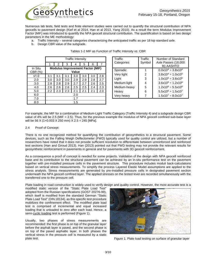
For example, the MIF for a combination of Medium-Light Traffic Category (Traffic Intensity 4) and a subgrade design CBR value of 4% will be 2.5 (MIF = 2.5). Thus, for the previous example the modulus of NPA geocell confined sub-base layer will be 56 X (1+0.003 X 250 mm) X 2.5 = 245 [MPa]. 2.4 Proof of Concept There is no one recognized method for quantifying the contribution of geosynthetics to a structural pavement. Some devices, such as the Falling Weigh Deflectometer (FWD) typically used for quality control are utilized, but a number of researchers have noted that it does not provide sufficient resolution to differentiate between unreinforced and reinforced test sections (Han and Giroud 2013). Han (2013) pointed out that FWD testing may not provide the relevant results for geosynthetic reinforcement in pavements in general and for pavements with 3D geocell reinforcement. As a consequence a proof of concept is needed for some projects. Validation of the design with NPA geocell reinforced base and its contribution to the structural pavement can be achieved by an in-situ performance test on the pavement together with pre-installed pressure cells in the pavement structure. This procedure includes moduli back-calculations based on vertical stress measurements. To simplify the process Layered Elastic Model assumptions are applied to the stress analysis. Stress measurements are generated by pre-installed pressure cells in designated pavement section underneath the NPA geocell confined layer. The applied stresses on the tested level are recorded simultaneously with the transferred one to the pressure cell. Plate loading in road construction is widely used to verify design and quality control. However, the most accurate test is a modified static version of the "Static Plate Load Test" adopted from the Russian specifications (GOST 20276-99), which itself is modified from the standard German "Static Plate Load Test" (DIN 18134), as this specific test procedure mobilizes the confinement effect. The modified plate load test is comprised of incremental and equal increased loading that is unloaded to zero after each load. Hence, a semi-cyclic loading test is performed (Figure 1). Usually, two phases of stress measurements are recommended: the first phase is on top of the granular layer before the asphalt layer is paved, and the second phase is on top of the paved asphaltic layer. In both phases the vertical stress in the pressure cell is measured by a static plate test.
Traffic Intensity
1 2 3 4 5 6 7
In Situ CBR (%)
Modulus Improvement Factor (MIF) Value
≤1.0 3.1 3.1 3.1 3.0 3.0 3.0 2.8
2.0 3.0 3.0 3.0 2.9 2.9 2.8 2.7
3.0 2.8 2.8 2.9 2.7 2.7 2.6 2.5
4.0 2.6 2.6 2.6 2.5 2.5 2.4 2.3
5.0 2.2 2.3 2.3 2.1 2.1 2.1 2.0
6.0 2.0
7.0 1.7
8.0 1.5
Traffic Categories
Traffic Symbol
Number of Standard Axle Passes (18,000
lb) AASHTO
Sporadic 1 0.0x10⁴ ÷ 3.8x10⁴
Very light 2 3.8x10⁴ ÷ 1.0x10⁵
Light 3 1.0x10⁵ ÷ 3.6x10⁵
Medium-light 4 3.6x10⁵ ÷ 1.2x10⁶
Medium-heavy 5 1.2x10⁶ ÷ 5.5x10⁶
Heavy 6 5.5x10⁶ ÷ 1.5x10⁷
Very heavy 7 1.5x10⁷ ÷ 8.0x10⁷
Figure 1. Plate load testing on surface of granular layer
Geosynthetics 2015 February 15-18, Portland, Oregon
4/10
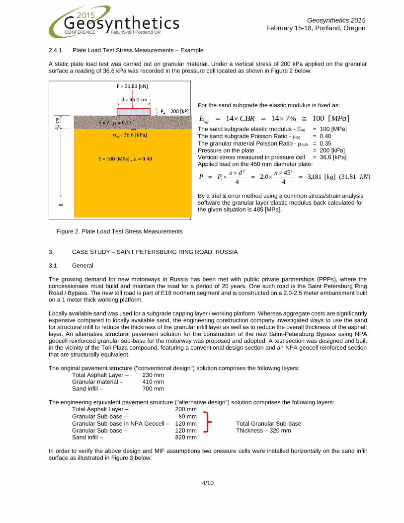
2.4.1 Plate Load Test Stress Measurements – Example A static plate load test was carried out on granular material. Under a vertical stress of 200 kPa applied on the granular surface a reading of 36.6 kPa was recorded in the pressure cell located as shown in Figure 2 below:
For the sand subgrade the elastic modulus is fixed as:
The sand subgrade elastic modulus - Esg = 100 [MPa]
The sand subgrade Poisson Ratio - sg = 0.40
The granular material Poisson Ratio - sub = 0.35 Pressure on the plate = 200 [kPa] Vertical stress measured in pressure cell = 36.6 [kPa] Applied load on the 450 mm diameter plate:
)81.31(][181,34
450.2
4
22
kNkgd
PP e
By a trial & error method using a common stress/strain analysis software the granular layer elastic modulus back calculated for the given situation is 485 [MPa].
Figure 2. Plate Load Test Stress Measurements
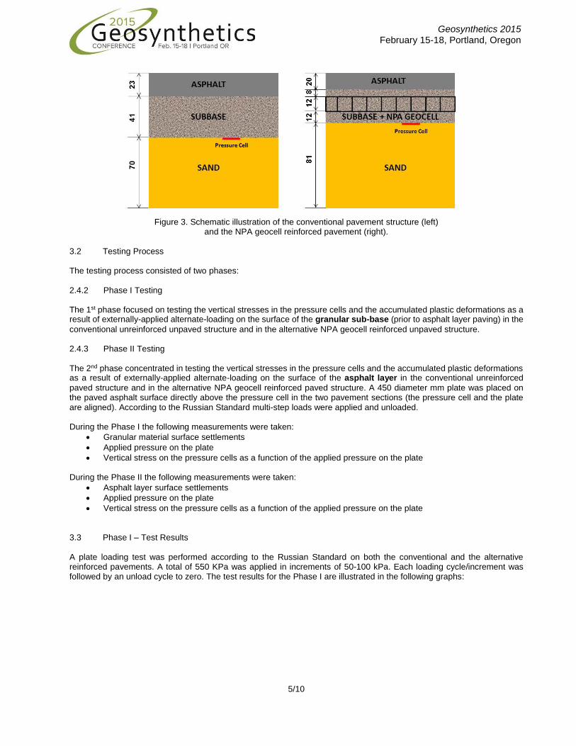
3. CASE STUDY – SAINT PETERSBURG RING ROAD, RUSSIA 3.1 General The growing demand for new motorways in Russia has been met with public private partnerships (PPPs), where the concessionaire must build and maintain the road for a period of 20 years. One such road is the Saint Petersburg Ring Road / Bypass. The new toll road is part of E18 northern segment and is constructed on a 2.0-2.5 meter embankment built on a 1 meter thick working platform. Locally available sand was used for a subgrade capping layer / working platform. Whereas aggregate costs are significantly expensive compared to locally available sand, the engineering construction company investigated ways to use the sand for structural infill to reduce the thickness of the granular infill layer as well as to reduce the overall thickness of the asphalt layer. An alternative structural pavement solution for the construction of the new Saint-Petersburg Bypass using NPA geocell reinforced granular sub-base for the motorway was proposed and adopted. A test section was designed and built in the vicinity of the Toll-Plaza compound, featuring a conventional design section and an NPA geocell reinforced section that are structurally equivalent. The original pavement structure ("conventional design") solution comprises the following layers:
Total Asphalt Layer – 230 mm Granular material – 410 mm Sand infill – 700 mm
The engineering equivalent pavement structure ("alternative design") solution comprises the following layers:
Total Asphalt Layer – 200 mm
Granular Sub-base – 80 mm
Granular Sub-base in NPA Geocell – 120 mm Total Granular Sub-base Granular Sub-base – 120 mm Thickness – 320 mm Sand infill – 820 mm
In order to verify the above design and MIF assumptions two pressure cells were installed horizontally on the sand infill surface as illustrated in Figure 3 below:
][100%71414 MPaCBREsg
Geosynthetics 2015 February 15-18, Portland, Oregon
5/10
Figure 3. Schematic illustration of the conventional pavement structure (left)
and the NPA geocell reinforced pavement (right). 3.2 Testing Process The testing process consisted of two phases: 2.4.2 Phase I Testing
The 1st phase focused on testing the vertical stresses in the pressure cells and the accumulated plastic deformations as a result of externally-applied alternate-loading on the surface of the granular sub-base (prior to asphalt layer paving) in the
conventional unreinforced unpaved structure and in the alternative NPA geocell reinforced unpaved structure. 2.4.3 Phase II Testing The 2nd phase concentrated in testing the vertical stresses in the pressure cells and the accumulated plastic deformations as a result of externally-applied alternate-loading on the surface of the asphalt layer in the conventional unreinforced
paved structure and in the alternative NPA geocell reinforced paved structure. A 450 diameter mm plate was placed on the paved asphalt surface directly above the pressure cell in the two pavement sections (the pressure cell and the plate are aligned). According to the Russian Standard multi-step loads were applied and unloaded. During the Phase I the following measurements were taken:
Granular material surface settlements
Applied pressure on the plate
Vertical stress on the pressure cells as a function of the applied pressure on the plate During the Phase II the following measurements were taken:
Asphalt layer surface settlements
Applied pressure on the plate
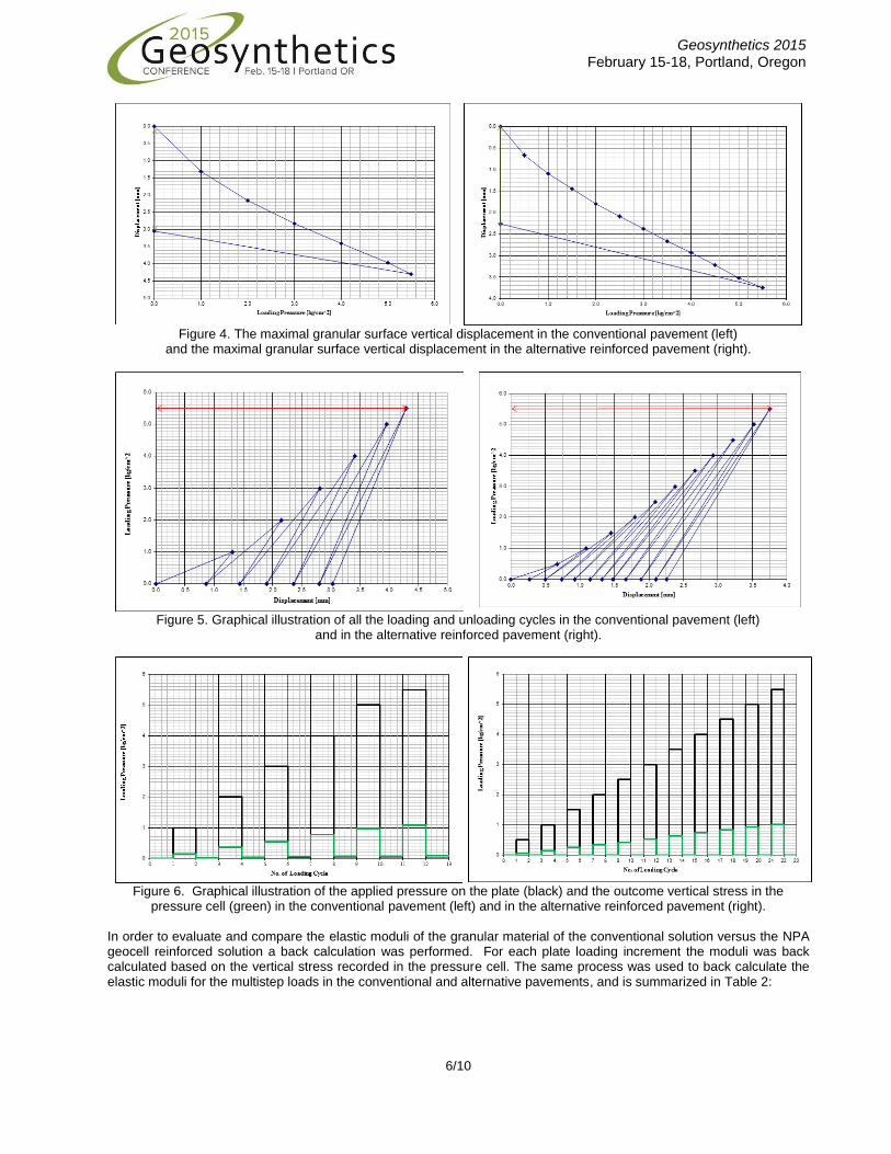
Vertical stress on the pressure cells as a function of the applied pressure on the plate 3.3 Phase I – Test Results A plate loading test was performed according to the Russian Standard on both the conventional and the alternative reinforced pavements. A total of 550 KPa was applied in increments of 50-100 kPa. Each loading cycle/increment was followed by an unload cycle to zero. The test results for the Phase I are illustrated in the following graphs:
Geosynthetics 2015 February 15-18, Portland, Oregon
6/10
Figure 4. The maximal granular surface vertical displacement in the conventional pavement (left)
and the maximal granular surface vertical displacement in the alternative reinforced pavement (right).
Figure 5. Graphical illustration of all the loading and unloading cycles in the conventional pavement (left) and in the alternative reinforced pavement (right).
Figure 6. Graphical illustration of the applied pressure on the plate (black) and the outcome vertical stress in the
pressure cell (green) in the conventional pavement (left) and in the alternative reinforced pavement (right). In order to evaluate and compare the elastic moduli of the granular material of the conventional solution versus the NPA geocell reinforced solution a back calculation was performed. For each plate loading increment the moduli was back calculated based on the vertical stress recorded in the pressure cell. The same process was used to back calculate the elastic moduli for the multistep loads in the conventional and alternative pavements, and is summarized in Table 2:
Geosynthetics 2015 February 15-18, Portland, Oregon
7/10
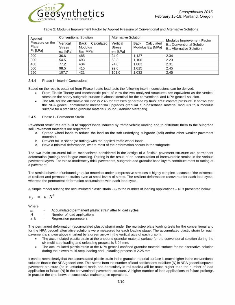
Table 2: Modulus Improvement Factor by Applied Pressure of Conventional and Alternative Solutions
Applied Pressure on the Plate Pe [kPa]
Conventional Solution Alternative Solution Modulus Improvement Factor
Esb Conventional Solution Esb Alternative Solution
Vertical Stress
zz [kPa]
Back Calculated Modulus Esb [MPa]
Vertical Stress
zz [kPa]
Back Calculated Modulus Esb [MPa]
200 36.6 485 34.9 1,137 2.34
300 54.5 493 53.3 1,100 2.23
400 77.2 434 74.6 1,003 2.31
500 98.5 415 92.6 1,015 2.45
550 107.7 421 101.0 1,032 2.45
2.4.4 Phase I - Interim Conclusions Based on the results obtained from Phase I plate load tests the following interim conclusions can be derived:
From Elastic Theory and mechanistic point of view the two analyzed structures are equivalent as the vertical stress on the sandy subgrade surface is almost identical for the conventional and NPA geocell solution.
The MIF for the alternative solution is 2.45 for stresses generated by truck tires’ contact pressure. It shows that the NPA geocell confinement mechanism upgrades granular sub-base/base material modulus to a modulus suitable for a stabilized granular material (Bound Granular Materials).
2.4.5 Phase I - Permanent Strain Pavement structures are built to support loads induced by traffic vehicle loading and to distribute them to the subgrade soil. Pavement materials are required to:
a. Spread wheel loads to reduce the load on the soft underlying subgrade (soil) and/or other weaker pavement materials.
b. Prevent fail in shear (or rutting) with the applied traffic wheel loads. c. Have a minimal deformation, where most of the deformation occurs in the subgrade.
The two main structural failure mechanisms considered in the design of a flexible pavement structure are permanent deformation (rutting) and fatigue cracking. Rutting is the result of an accumulation of irrecoverable strains in the various pavement layers. For thin to moderately thick pavements, subgrade and granular base layers contribute most to rutting of a pavement. The strain behavior of unbound granular materials under compressive stresses is highly complex because of the existence of resilient and permanent strains even at small levels of stress. The resilient deformation recovers after each load cycle, whereas the permanent deformation accumulates with each load cycle.
A simple model relating the accumulated plastic strain - p to the number of loading applications – N is presented below:
Where:
p = Accumulated permanent plastic strain after N load cycles
N = Number of load applications a, b = Regression parameters
The permanent deformation (accumulated plastic strain) under the multistep plate loading tests for the conventional and for the NPA geocell alternative solutions were measured for each loading stage. The accumulated plastic strain for each pavement is shown above (marked by a green arrow in the vertical axis of each graph).
The accumulated plastic strain at the unbound granular material surface for the conventional solution during the six multi-step loading and unloading process is 3.04 mm.
The accumulated plastic strain at the NPA geocell confined granular material surface for the alternative solution during the eleven multi-step loading and unloading process is 2.25 mm.
It can be seen clearly that the accumulated plastic strain in the granular material surface is much higher in the conventional solution than in the NPA geocell one. This stems from the number of load applications to failure (N) in NPA geocell unpaved pavement structure (as in unsurfaced roads and particularly in rail tracks) will be much higher than the number of load application to failure (N) in the conventional pavement structure. A higher number of load applications to failure prolongs in practice the time between successive maintenance operations.
b
P Na
Geosynthetics 2015 February 15-18, Portland, Oregon
8/10
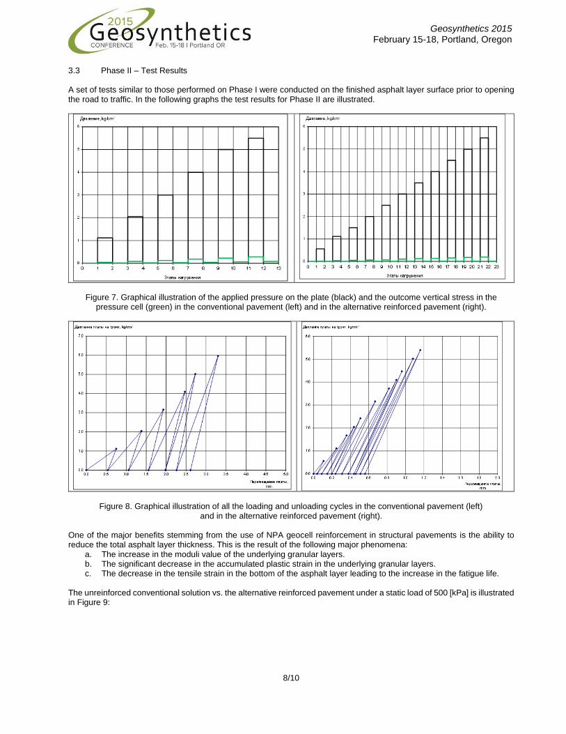
3.3 Phase II – Test Results A set of tests similar to those performed on Phase I were conducted on the finished asphalt layer surface prior to opening the road to traffic. In the following graphs the test results for Phase II are illustrated.
Figure 7. Graphical illustration of the applied pressure on the plate (black) and the outcome vertical stress in the
pressure cell (green) in the conventional pavement (left) and in the alternative reinforced pavement (right).
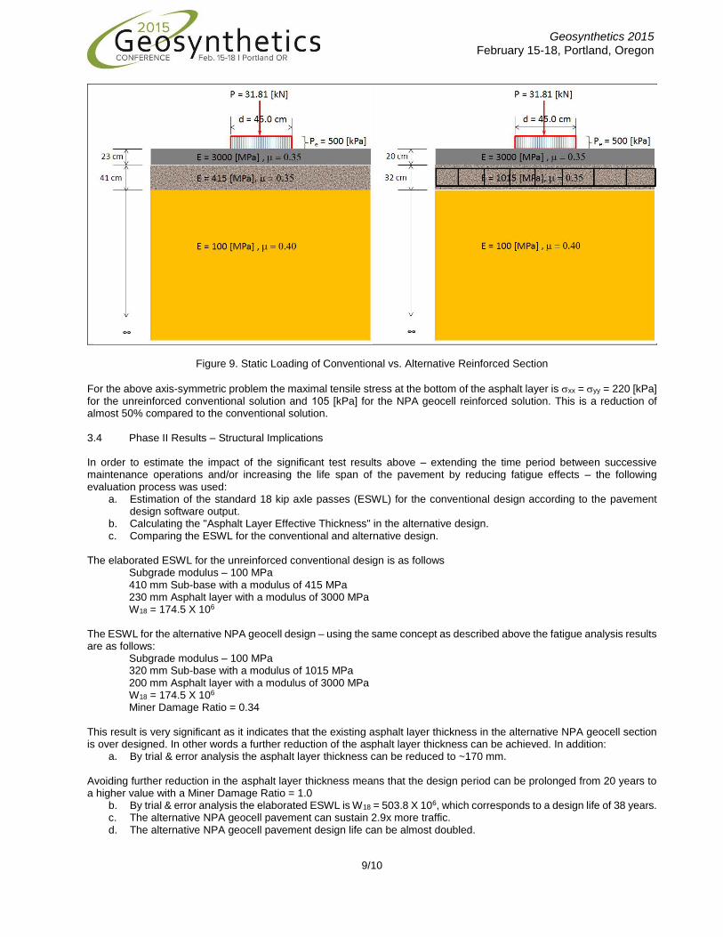
Figure 8. Graphical illustration of all the loading and unloading cycles in the conventional pavement (left) and in the alternative reinforced pavement (right).
One of the major benefits stemming from the use of NPA geocell reinforcement in structural pavements is the ability to reduce the total asphalt layer thickness. This is the result of the following major phenomena:
a. The increase in the moduli value of the underlying granular layers. b. The significant decrease in the accumulated plastic strain in the underlying granular layers. c. The decrease in the tensile strain in the bottom of the asphalt layer leading to the increase in the fatigue life.
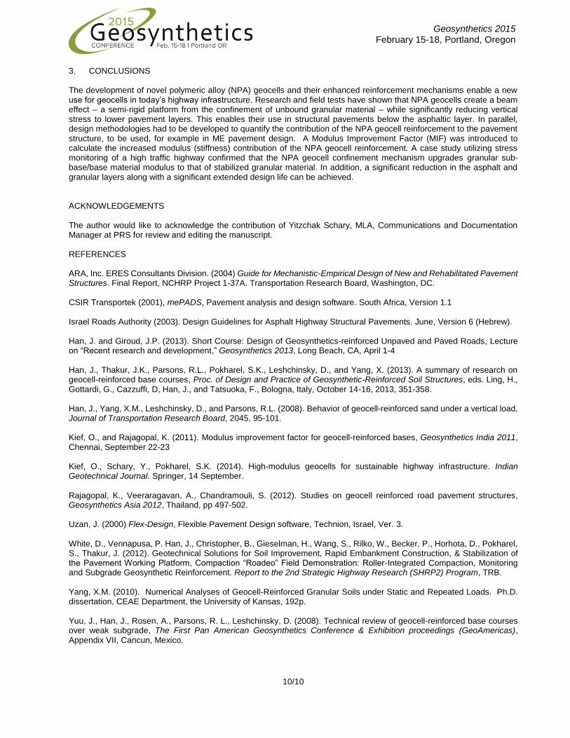
The unreinforced conventional solution vs. the alternative reinforced pavement under a static load of 500 [kPa] is illustrated in Figure 9:
Geosynthetics 2015 February 15-18, Portland, Oregon
9/10
Figure 9. Static Loading of Conventional vs. Alternative Reinforced Section
For the above axis-symmetric problem the maximal tensile stress at the bottom of the asphalt layer is xx = yy = 220 [kPa] for the unreinforced conventional solution and 501 [kPa] for the NPA geocell reinforced solution. This is a reduction of almost 50% compared to the conventional solution. 3.4 Phase II Results – Structural Implications In order to estimate the impact of the significant test results above – extending the time period between successive maintenance operations and/or increasing the life span of the pavement by reducing fatigue effects – the following evaluation process was used:
a. Estimation of the standard 18 kip axle passes (ESWL) for the conventional design according to the pavement design software output.
b. Calculating the "Asphalt Layer Effective Thickness" in the alternative design. c. Comparing the ESWL for the conventional and alternative design.
The elaborated ESWL for the unreinforced conventional design is as follows
Subgrade modulus – 100 MPa 410 mm Sub-base with a modulus of 415 MPa 230 mm Asphalt layer with a modulus of 3000 MPa W18 = 174.5 X 10⁶
The ESWL for the alternative NPA geocell design – using the same concept as described above the fatigue analysis results are as follows:
Subgrade modulus – 100 MPa 320 mm Sub-base with a modulus of 1015 MPa 200 mm Asphalt layer with a modulus of 3000 MPa W18 = 174.5 X 10⁶
Miner Damage Ratio = 0.34 This result is very significant as it indicates that the existing asphalt layer thickness in the alternative NPA geocell section is over designed. In other words a further reduction of the asphalt layer thickness can be achieved. In addition:
a. By trial & error analysis the asphalt layer thickness can be reduced to ~170 mm. Avoiding further reduction in the asphalt layer thickness means that the design period can be prolonged from 20 years to a higher value with a Miner Damage Ratio = 1.0
b. By trial & error analysis the elaborated ESWL is W18 = 503.8 X 10⁶, which corresponds to a design life of 38 years. c. The alternative NPA geocell pavement can sustain 2.9x more traffic. d. The alternative NPA geocell pavement design life can be almost doubled.
Geosynthetics 2015 February 15-18, Portland, Oregon
10/10
3. CONCLUSIONS The development of novel polymeric alloy (NPA) geocells and their enhanced reinforcement mechanisms enable a new use for geocells in today’s highway infrastructure. Research and field tests have shown that NPA geocells create a beam effect – a semi-rigid platform from the confinement of unbound granular material – while significantly reducing vertical stress to lower pavement layers. This enables their use in structural pavements below the asphaltic layer. In parallel, design methodologies had to be developed to quantify the contribution of the NPA geocell reinforcement to the pavement structure, to be used, for example in ME pavement design. A Modulus Improvement Factor (MIF) was introduced to calculate the increased modulus (stiffness) contribution of the NPA geocell reinforcement. A case study utilizing stress monitoring of a high traffic highway confirmed that the NPA geocell confinement mechanism upgrades granular sub-base/base material modulus to that of stabilized granular material. In addition, a significant reduction in the asphalt and granular layers along with a significant extended design life can be achieved. ACKNOWLEDGEMENTS The author would like to acknowledge the contribution of Yitzchak Schary, MLA, Communications and Documentation Manager at PRS for review and editing the manuscript. REFERENCES ARA, Inc. ERES Consultants Division. (2004) Guide for Mechanistic-Empirical Design of New and Rehabilitated Pavement Structures. Final Report, NCHRP Project 1-37A. Transportation Research Board, Washington, DC. CSIR Transportek (2001), mePADS, Pavement analysis and design software. South Africa, Version 1.1 Israel Roads Authority (2003). Design Guidelines for Asphalt Highway Structural Pavements. June, Version 6 (Hebrew). Han, J. and Giroud, J.P. (2013). Short Course: Design of Geosynthetics-reinforced Unpaved and Paved Roads, Lecture on “Recent research and development,” Geosynthetics 2013, Long Beach, CA, April 1-4 Han, J., Thakur, J.K., Parsons, R.L., Pokharel, S.K., Leshchinsky, D., and Yang, X. (2013). A summary of research on geocell-reinforced base courses, Proc. of Design and Practice of Geosynthetic-Reinforced Soil Structures, eds. Ling, H., Gottardi, G., Cazzuffi, D, Han, J., and Tatsuoka, F., Bologna, Italy, October 14-16, 2013, 351-358. Han, J., Yang, X.M., Leshchinsky, D., and Parsons, R.L. (2008). Behavior of geocell-reinforced sand under a vertical load, Journal of Transportation Research Board, 2045, 95-101. Kief, O., and Rajagopal, K. (2011). Modulus improvement factor for geocell-reinforced bases, Geosynthetics India 2011, Chennai, September 22-23 Kief, O., Schary, Y., Pokharel, S.K. (2014). High-modulus geocells for sustainable highway infrastructure. Indian Geotechnical Journal. Springer, 14 September. Rajagopal, K., Veeraragavan, A., Chandramouli, S. (2012). Studies on geocell reinforced road pavement structures, Geosynthetics Asia 2012, Thailand, pp 497-502. Uzan, J. (2000) Flex-Design, Flexible Pavement Design software, Technion, Israel, Ver. 3. White, D., Vennapusa, P. Han, J., Christopher, B., Gieselman, H., Wang, S., Rilko, W., Becker, P., Horhota, D., Pokharel, S., Thakur, J. (2012). Geotechnical Solutions for Soil Improvement, Rapid Embankment Construction, & Stabilization of the Pavement Working Platform, Compaction “Roadeo” Field Demonstration: Roller-Integrated Compaction, Monitoring and Subgrade Geosynthetic Reinforcement. Report to the 2nd Strategic Highway Research (SHRP2) Program, TRB.
Yang, X.M. (2010). Numerical Analyses of Geocell-Reinforced Granular Soils under Static and Repeated Loads. Ph.D. dissertation, CEAE Department, the University of Kansas, 192p. Yuu, J., Han, J., Rosen, A., Parsons, R. L., Leshchinsky, D. (2008). Technical review of geocell-reinforced base courses over weak subgrade, The First Pan American Geosynthetics Conference & Exhibition proceedings (GeoAmericas), Appendix VII, Cancun, Mexico.