Embed Size (px)
Citation preview

STRUCTURAL HEALTH MONITORING OF AN INNOVATIVE TIMBER BUILDING
Claude Leyder 1,*, Eleni Chatzi 1 and Andrea Frangi1 1 Institute of Structural Engineering (IBK),
Department of Structural, Environmental and Geomatic Engineering (D-BAUG), ETH Zürich, Stefano Franscini Platz 5 - CH 8093 Zürich, Switzerland.*Email:[email protected]
ABSTRACT A main focus in timber construction research is the development of innovative, sustainable and reliable structures. In order to determine the long-term structural behaviour of these novel structures, structural health monitoring is a valuable tool. In the past two years an innovative timber-hybrid pilot building has been conceived, designed and realized at ETH Zürich. The building contains four innovative structural systems, a post-tensioned timber frame, two timber-concrete hybrid floor systems using beech LVL, and a biaxial pure timber floor in beech wood. In order to fully understand the combined structural behaviour of these innovative systems an extensive monitoring system was set up. The dense sensor network was implemented along with the construction progress, in order to also quantify the effects of important construction stages on the structural behaviour (addition of significant loads, addition of stiffening elements, extreme changes in environmental climate, etc.). The installed setup includes 16 load cells, measuring the changes in the post-tension force in the frame, absolute deformation measurements, temperature and relative humidity sensors, as well as measurements of the moisture content of timber. The monitoring campaign is planned to be continued for several years beyond the completion of construction, in order to quantify the long-term behaviour during the use phase of the building. KEYWORDS Innovative hybrid-timber structure, Long-term structural performance, Structural monitoring under construction. INTRODUCTION Nowadays, the development of innovative structures, which are efficient and reliable throughout their life-cycle, is a main focus in the timber engineering field. Especially the implementation of hardwood elements opens up a whole range of new possibilities for timber structures. This is indeed favoured by the optimal strength and stiffness properties of hardwood. In addition hardwood is largely available in Swiss Forests and new implementations for the material are currently being investigated. Innovative structural systems are mostly developed and tested under laboratory conditions, i.e., small to mid-scale sample sizes in a controlled environment. From these tests valuable information about the short-term structural behaviour can be gained. However, the knowledge concerning the structural behaviour in an actual-scale building situation as well as in a long-term use, is limited. Therefore a pilot building demonstrating the implementation of hardwood as structural elements has been realized at ETH Zürich, under a project titled ``ETH House of Natural Resources (ETH HoNR)'' (Leyder et al. 2015). The building allows for the quantification of the structural behaviour of several innovative structures in a real building situation. Starting from summer 2015, the building will be used as an office building by the Laboratory of Hydraulics, Hydrology and Glaciology (VAW) from ETH Zürich. The structure of the ETH HoNR is described in detail in Leyder et al. 2015. The following sections contains a short summary of the aspects that are most relevant for the monitoring setup. The ETH HoNR comprises four innovative structural systems using especially hardwood. The main lateral and vertical load-carrying structure is a post-tensioned timber frame, using columns made of ash wood, hybrid timber beams composed of ash and spruce and a steel tendon. The tendons span over the whole building length at mid-height of the beam, in a horizontal hole in the middle of the beam cross-section. The post-tensioned frame was developed and extensively tested in the ETH laboratory (Wanninger and Frangi 2014, Leyder et al. 2014). Two types of laboratory tests were conducted, first a single column-beam joint specimen was tested and second a two-dimensional 19.5m long, three-bay (3*6.5m span) frame was tested. The exact same frame is implemented in the ETH HoNR building in a three-dimensional setup, with spans of 6.5m in both directions, leading to a floor section of 19.5m*19.5m. In Figure 1 the position of the frame is highlighted in the floor plan of the first timber story and in the section of the building. The columns are entirely produced in ash wood and have a cross-section of 380mm*380mm. The beams are hybrid timber beams with four lower lamellas in ash wood and the remaining upper lamellas in spruce wood. The total cross-section of the beams is 280mm*720mm. The semi-rigid joint between the columns and the beams is created via the post-tension force, no additional steel
1383

elements are necessary. Therefore the construction of the frame is very fast ( 1) positioning of the columns, 2) mounting of the beams and 3) post-tensioning). The post-tension cables are post-tensioned to 700kN, which corresponds to a compressive stress of 3.5MPa in the beams. The small support attached to the column is mostly used for the mounting of the beams. Figure 3 a) shows a picture of the joint.
Figure 1 Floor plan and section of the ETH HONR building (Post-tensioned timber frame highlighted in green) (by mml architects) The second innovative structural system is the mid-floor. It is a concrete-timber composite floor, composed of 40mm thick beech LVL plates and a 160mm concrete plate. The beech plates span also 6.5m and are supported on the frame. The concrete plate was cast on-site as a continuous element. This floor system was also developed at ETH Zürich, as described in Boccadoro and Frangi 2013. Figure 2 a) shows the installation of the beech LVL plates on the construction site of the ETH HoNR before the pouring of the concrete. For the top floor (roof structure) two further innovative systems were implemented. One is a slab purely made of beech wood, with a bi-axial load-carrying capacity (Wanninger and Frangi 2012). This structure was only implemented in the centre field (elevated roof section in Figure 1), with an area of 6.5m*6.5m. The slab is composed of a 120mm thick 5-ply beech CLT plate (ply thicknesses: 20mm-30mm-20mm-30mm-20mm), rectangular posts in beech LVL (170mm high) and 40mm thick beech lamellas running cross-wise. The CLT plate was separated into three elements, which were then screwed together on site (transportable dimensions of 2.17m*6.5m). The addition of the lower cross-wise lamellas leads to a significant increase in stiffness and favours the bi-directional load distribution. Figure 2 b) shows a picture of the structure of the bi-axial floor from below (visible ceiling). The structure of the remaining 8 fields of the roof is a hollow timber-concrete composite floor. The lower plate of the hollow section is also a 40mm thick beech LVL plate, connected via posts (240mm high) to the top plate, a 70mm thick prefabricated concrete plate. The concrete plate is connected to the posts via diagonal screws, a system developed by the company Häring.
Figure 2 a) Beech plates for the timber-concrete composite floor b) Bi-axial timber floor in beech wood
1384

The goal of the current research work is to study the structural behaviour of these different structural systems and their interaction, as well as the influence of environmental effects on the structural behaviour. Therefore several series of modal dynamic tests have been carried out during the construction phase and a dense monitoring setup has been implemented. The monitoring setup was implemented along with the construction progress in order to also capture the structure’s reaction to the addition of loads, as well as to significant environmental changes (e.g. the change from outdoor climate to indoor climate). The building envelope is composed of a glass façade and a conventional roof (waterproofing – insulation – extensive vegetation). The indoor climate can be controlled by the user via the activation of shading elements and the opening / closing of windows. No automatic ventilation is installed. Structural health monitoring is a very valuable tool for quantifying the structural behaviour and the condition of civil engineering structures. Especially for new and complex structural systems the implementation of a monitoring setup can help to verify design assumptions and to obtain information about the long-term behaviour of structures. With the development and construction of more and more complex structures, the necessity for monitoring is increasing not only in order to verify design assumptions but also to guarantee a long lifespan of structures (e.g. early detection of necessary repairs). In Aoki et al. 2003, many aspects of structural health monitoring are discussed and illustrated with implementation examples for infrastructural systems. The book by Glisic and Inaudi 2008 demonstrates especially the implementation of fibre optical sensors for structural health monitoring. An implementation of fibre optical sensors on a nineteen story building can be found in Glisic et al. 2003. In the ETH HoNR several high-end monitoring systems are implemented to analyse the structural behaviour, verify the design assumptions and to quantify the long-term behaviour of the timber structure. The paper is organized as follows: The first part (monitoring - instrumentation) describes the implemented monitoring setup on the timber structure, followed by a section which presents and discusses monitoring results from the construction phase. Especially the results from the load cells measurements are then discussed in the discussion section and, the final section provides some concluding remarks along with further research efforts undertaken by the group. MONITORING - INSTRUMENTATION In order to fully quantify the structural behaviour of the building a dense network of different sensor types was implemented. The implemented sensors range from load cells, timber moisture content measurements to deformation measurements. In the following section the functionality and implemented setup of the sensor configurations will be illustrated. Load cells The post-tensioned timber frame is the main load carrying system for horizontal and vertical loads inside the building. The connection between the columns and the beams is assured only via the post-tension force, no additional steel connectors are added. Therefore the post-tension force in the tendons is a very important parameter for the entire stiffness and robustness of the building. Post-tensioning of timber is a novel technology, and the knowledge about the long-term behaviour (e.g. due to creep of timber) is limited. Indeed the post-tensioning creates large stresses perpendicular to the grain in the column area, which may lead to large creep deformations. Furthermore changes in timber moisture content may lead to shrinkage and swelling and therefore lead to additional stresses in the joint. This phenomena has been studied on small scale specimens documented in Wanninger et al. 2015. From these test results, a 30% loss of tendon force was predicted for the service life of a posttensioned timber structure. The post-tensioning of the building was designed according to these results. In addition a load cell was installed in each tendon, which constantly measures the post-tensioning force. Since the structure comprises 2 stories with 4 frames in each direction, in total 16 load cells were installed. Figure 3 b) shows a picture from the installation process of the load cell. The load cells is mounted between the tendon anchorage and the load distribution steel plate fixed to the timber column.
1385

Figure 3 a) Joint between the column and the beams b) Installation of a load cell (tendon anchorage point) Moisture content of timber In order to better understand the relation between creep, shrinkage and post-tension losses, the moisture content inside the timber is monitored. The moisture content of the timber is measured via the electric resistance method, where insulated steel needles are drilled into the timber to a certain depth (measurement at the tip of the needle). A detailed overview of moisture content measurements in timber is given in Forsén and Tarvainen 2000, where also advantages and disadvantages of different measurement methods are discussed. In the building, several moisture content sensors (a pair of insulated steel needles) are implemented along the timber frame at a depth of 6cm (Figure 4 a)). On each floor 20 measurement points in beams and columns were installed. In the hybrid beams measurement points were installed in the ash wood and in the spruce wood. Furthermore the moisture content is also recorded in the beech CLT plate of the roof structure in the central field. In the 5-ply 120mm thick CLT plate the insulated steel needles were installed at 5 different depths (middle of each ply – depths of 10mm, 35mm, 60mm, 85mm, 110mm) (Figure 4 b)). As the 6.5m*6.5m CLT plate was assembled from 3 separate plates (2.17m*6.5m), 5*3 measurement points were installed.
Figure 4 Moisture content measurement inside the timber a) Insulated steel needles inside a timber column b) Insulated steel needles inside the beech CLT plate at 5 different depths Temperature and relative humidity Temperature and relative humidity are also relevant parameters since they may significantly influence the moisture content of timber and therefore also its mechanical properties (Niemz 1993). During the construction period a single climate station was installed on the construction site monitoring temperature and relative humidity. It was assumed that throughout the construction site the climate is more or less constant, since the airflow is not hindered by any internal walls or the façade. After the installation of the walls and the façade, 12 combined sensors (temperature and relative humidity) were installed in 12 different rooms. Indeed, since the indoor climate can be controlled by the user himself (opening of windows / activation of shading), the climate might vary significantly from room to room.
1386

Vibration sensors In addition to the static monitoring setups, dynamic sensors were also installed inside the building. These were used during the dynamic test phases inside the building and will also be used during the use phase for structural identification and model updating on the basis of ambient vibrations. The idea is to evaluate changes in dynamical properties, and therefore system characteristics, and relate these to potential changes in stiffness, post-tension force, moisture content. The dynamic tests during the construction phase are documented in Leyder et al. 2015 and the ambient testing phase will start in summer 2015, after the building users have moved in. Deformation measurements Furthermore classical deformation measurements have been carried out. Two techniques were used, first classical levelling of mid-span points of floors and beams and second classical tachymeter measurements (also mid-span points of floor and beams). At the beginning an automated setup took hourly measurements of deflections. In a later phase, however, this was no longer possible due to the addition of the internal walls. Therefore only periodic tachymeter measurements were conducted combined with the classical levelling. The measurements were conducted in collaboration with the institute of geodesy and photogrammetry (IGP) of ETH Zürich. The combination of these different monitoring systems is a complex task. Especially the analysis of the interaction between the different recorded parameters requires a detailed study and also quantification of external effects, that may not have been recorded (e.g. disturbances of the system due to construction works etc.). In the following section some results from the monitoring campaign will be presented. The focus lies on the results concerning the post-tensioned timber frame and moisture content measurements in timber. MONITORING – RESULTS FROM MONITORING UNDER CONSTRUCTION The construction of the building started in September 2013 and the sensors were installed along with the construction process. The first 8 load cells were installed with the first-storey timber frame in January 2014. The 8 load cells on the second story were added with the frame on the second story in July 2014. The moisture content measurements in the timber frame were installed at the same time as the respective frame. During the construction phase the air temperature and relative humidity were only recorded in a single position (climate station), as the construction was only protected by a weather proof membrane and the air could circulate freely through the whole structure. After the installation of the internal walls and the façade, several indoor climate sensors were distributed in different rooms and a climate station was installed on the roof in order to monitor also the outside climate conditions (February 2015). The deformation measurements of the first story started after the installation of the beech LVL plates on top of the post-tensioned timber frame (March 2014). The deformation measurements on the second story started after completion of the roof structure (November 2014). The starting dates of the measurements are also documented in Table 1. For the deformation measurements two different techniques were combined using each a different number of measuring points (~20), therefore no value is reported in the column “amount” in Table 1. The presented data was recorded either with an automated data acquisition unit (load cells, temperature and relative humidity of the air) or manually (moisture content in timber). For the automated data acquisition daily mean values were calculated and are presented herein, for the manual measurement data was taken weekly (moisture content in the bi-axial floor) or every 3-4 weeks (deformation measurements, moisture content in the Post-tensioned (PT) frame). The data is presented until the end of May 2015. Monitoring under construction is a challenging task, as some construction works may require re-cabling of sensors and frequent power cuts may lead to losses of data. In this project data was recorded on as many days as possible, some gaps in the data could however not be avoided.
Table 1 Overview of instrumentation Amount Start of operation Load cells 1st story 8 cells January 2014 Load cells 2nd story 8 cells July 2014 Moisture content frame 1st story 21 locations January 2014 Moisture content frame 2nd story 20 locations July 2014 Moisture content bi-axial timber slab 15 locations October 2014 Temperature and relative humidity (construction site) 1 location January 2014 – January 2015 Temperature and relative humidity (closed building) 12 locations February 2015 Temperature and relative humidity (outside on the roof) 1 location April 2015 Deformation measurements 1st story / March 2014 Deformation measurements 2nd story / November 2014
1387

Load cells The following 2 figures (Fig 5 and 6) show the evaluation of the post-tension force in the 16 frames (LC1-LC8 on the 1st story, LC9-LC16 on the 2nd story), measured via the load cells. For the first story only values after March 2014 are reported, even though the frame was post-tensioned in January 2014. In March 2014 the frame was re-post-tensioned in order to calibrate the load cells. Therefore the data is presented starting from March 2014.
Figure 5 Post-tension forces on the 1st story (LC1-LC8)
Figure 6 Post-tension forces on the 2nd story (LC9-LC12)
From the graphs it can be noted that all 8 load cells per story follow a similar pattern. The percentage of loss / gain in post-tensioning force is also indicated in the graphs. On the first story a 3% loss occurred during the first 4 months, followed by a stable phase of 6 months and then followed by another decrease of 1% in 4 months. On the second story the pattern is different, where first a 1.5% gain in post-tension force occurred during the first 4 months, followed then by a drop of 4.7% in the following 6.5 months.
1388
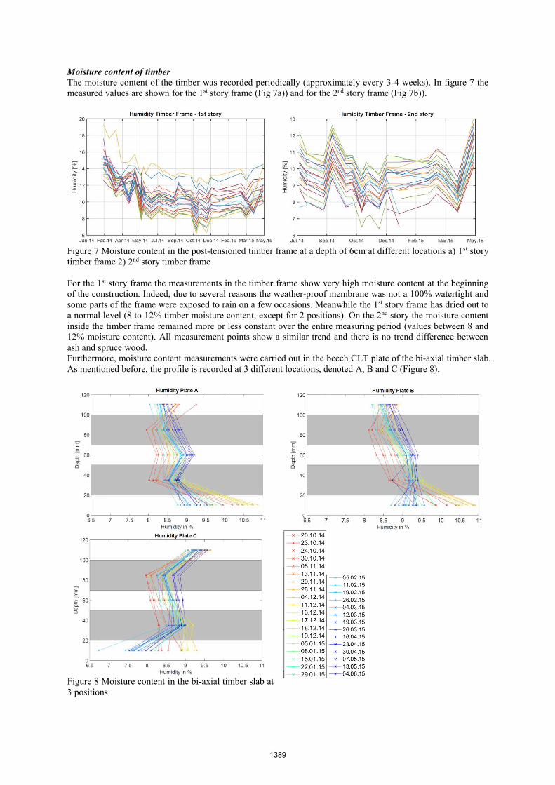
Moisture content of timber The moisture content of the timber was recorded periodically (approximately every 3-4 weeks). In figure 7 the measured values are shown for the 1st story frame (Fig 7a)) and for the 2nd story frame (Fig 7b)).
Figure 7 Moisture content in the post-tensioned timber frame at a depth of 6cm at different locations a) 1st story timber frame 2) 2nd story timber frame For the 1st story frame the measurements in the timber frame show very high moisture content at the beginning of the construction. Indeed, due to several reasons the weather-proof membrane was not a 100% watertight and some parts of the frame were exposed to rain on a few occasions. Meanwhile the 1st story frame has dried out to a normal level (8 to 12% timber moisture content, except for 2 positions). On the 2nd story the moisture content inside the timber frame remained more or less constant over the entire measuring period (values between 8 and 12% moisture content). All measurement points show a similar trend and there is no trend difference between ash and spruce wood. Furthermore, moisture content measurements were carried out in the beech CLT plate of the bi-axial timber slab. As mentioned before, the profile is recorded at 3 different locations, denoted A, B and C (Figure 8).
Figure 8 Moisture content in the bi-axial timber slab at 3 positions
1389

The colour code indicates the evaluation of the moisture content from the installation of the floor (October 2014) (red) until the end of May 2015 (blue). Measurements were taken every week. The y-axis shows the depth of the measurement in the 5 ply CLT plate (cross layers are indicated in grey) and the x-axis shows the moisture content in timber. The moisture variation profile has slightly changed from the installation of the floor until the end of May 2015. In the lowest ply (room-side) the moisture content was reduced by ~1%, whereas the four upper plies show a slight increase in moisture content (~1%). Temperature and relative humidity In addition to the moisture content inside the timber also the temperature and the relative humidity on the construction site and later inside the building have been recorded. As mentioned before, the climate was first recorded at a single point (continuous line in Figure 9), and second recorded at 12 different locations (dashed lines in Figure 9).
Figure 9 a) Temperature and b) Relative humidity (straight line until Feb 2015: climate during construction, dashed lines from Feb 2015 (climate after the building envelope was closed)) Before the completion of the building envelope in winter 2014/2015 the temperature and relative humidity measurements show a very high variability, as expected for outdoor climate. Temperatures increased during summer 2014 followed by a decrease towards winter. The heating inside the building was switched on in December 2014, the measurement system was however only switched to multiple locations in February 2015. The completion of the building envelope and the activation of the floor heating created a large drop in relative humidity (approximately from 60-70% to 30-50%). Since timber with small cross-section strongly reacts to large changes in relative humidity (Niemz 1993, Fragiacomo et al. 2011), several humidifiers were installed inside the building in order to avoid a further drop of relative humidity. The humidifiers shifted the relative humidity range from ~30-40% to ~40-50%. DISCUSSION OF MEASURED POST-TENSION FORCES The measured losses and gains in the post-tension forces can be compared to the small-scale experiments that were carried out in the laboratory (Wanninger et al. 2015). Therein, two series of specimens were monitored, 1 series in a controlled environment and 1 in an uncontrolled environment. During the first 3 months a loss of 6% in post-tension force was recorded in the controlled environment and a loss of 12% in the uncontrolled environment (Fig. 16 in Wanninger et al. 2015). The specimens used in these tests had a cross-section of 240mm*120mm and were post-tensioned to 3MPa. On the construction site of the House of Natural Resources building, however, the cables were post-tensioned to 3.5MPa and the cross-section of the beams is 720mm*280mm. For both setups, small-scale laboratory tests and building measurements, the moisture content was recorded at a depth of 60mm. One main difference is however the location of the tendon, which runs at a depth of 60mm for the small scale specimens and at a depth of 140mm for the frame of the building (measured from the side of the beam). These differences in cross-section size might explain the much smaller losses in post-tension force observed inside the building. Indeed, the paper by Friagiacomo (Fragiacomo et al. 2011) shows that the correlation between changes in relative humidity and the moisture content of timber (mean value) is strongly dependent on the cross-section size (Fragiacomo et al. 2011). This can explain why the change in relative humidity has a much stronger effect on shrinkage and swelling for the small scale specimens and therefore leads to higher losses in post-tension force for the small-scale specimens.
1390

Figure 10 Example of the correlation between the post-tension force in a frame from the 1st story (left-hand figure) and 2nd story (right-hand figure) and the moisture content measurement at 8 locations along the frame (each location is denoted with a different symbol and colour). The linear regression lines were added in the same colour. Indeed, the correlation coefficients between the relative humidity measurements and the losses / gains in post-tension force were calculated and were found to be very low for the building frame. In addition however also the correlation coefficients between the load cell measurements and the moisture content inside the timber cross-section were calculated. As an example, Figure 10 illustrates the correlation for one load cell and moisture measurements along the corresponding frame (at 6cm depth). For the 1st story frame a mean correlation coefficient of 0.74 with a standard deviation of 0.1 could be found. For the 2nd story the mean correlation coefficient is -0.55 with a standard deviation of 0.2. This indicates that for the 1st story there is a clear correlation between the initial drop in post-tension force and the initial drying of the timber (shrinkage). During the summer period of 2014 the drying of the timber cross-section stopped (high outdoor relative humidity), which is manifested by a stable phase in the post-tension force. The final decrease phase (Feb – May 2015) cannot be clearly correlated to the moisture content. For the 2nd story, the correlation is clearly less significant. Indeed the timber moisture content is nearly constant, whereas however the load cells indicate an increase and decrease in post-tension force. The moisture content measurements were only carried out every 3-4 weeks, this period may have been too long to clearly indicate a significant trend. The measurement frequency will therefore be increased to bi-weekly measurements in the future. Furthermore there might be a strong moisture gradient over the cross-section which also influences the post-tension force and cannot be measured by the current setup. A hypothesis is, that the timber members of the 2nd story were well dried (moisture content of ~10%) when they arrived at the construction site, so that the moisture content would first increase (high relative humidity) and then decrease with the start of winter and the heating period. This would then linearly correlate with the post-tension force (increase in moisture content leading to an increase in post-tension force and decrease in moisture content leading to a decrease in post-tension force). Indeed an increase in moisture content would lead to swelling of especially the column section and therefore induce higher stresses in the column-beam joint. Unfortunately, this trend could not be captured by the moisture content measurements. Other factors like creep, in combination with the addition / removal of loads may also have influenced the post-tension force. These factors will be further investigated in the future. The difference of the post-tension force losses between the 1st and the 2nd story may mostly be explained by the different climatic conditions and also the initial moisture content of the timber members. The frame of the 1st story was mounted in winter time and had a rather high initial moisture content. The timber members dried out to an equilibrium condition in summer 2014. This seems to be a valid explanation for the larger initial drop in post-tension force. The frame on the 2nd story was mounted in summer 2014 and the timber members had a lower initial moisture content. These 2 factors can explain why the loss in post-tension force between the 1st and the 2nd story strongly differ. It is expected that the behaviour will become more similar in the use phase of the building, were the climatic conditions will exhibit lower variations. CONCLUSIONS An innovative hybrid timber building is subjected to an extensive monitoring campaign. The paper presents first results from the measurements during the construction phase. Especially the losses in post-tension force are commented and put into relation with the indoor climate variations and the moisture content measurements inside the timber cross-section. The following conclusions can be summarized:
1391

x The loss in post-tension force on the 1st story correlates strongly with the changes in moisture content in timber.
x The loss in post-tension force on the 1st and 2nd story has no correlation with the changes in relative humidity. This may be explained by the large dimensions of the beam and column cross-sections.
x The loss and gain in post-tension force on the 2nd story cannot be explained via a direct correlation with the moisture content measurements. Other factors may be responsible for these changes.
x The difference in the loss of post-tension force between the 1st and the 2nd story may be explained by the different climatic conditions at the time of erection and also by the difference in initial moisture content.
x The moisture content in the bi-axial timber slab remained nearly constant. A drying out of the lower plate of ~1% was observed, which can be linked to the large drop in relative humidity after the closing of the building envelope.
At this point, the monitoring during the construction phase of the building was presented. The installed monitoring setups will however remain in operation for at least 3 more years after the beginning of the use phase of the building in summer 2015. From these measurements further insights regarding the long-term behaviour of the structure under operation will be gained, via monitoring of the evolution of structural properties with respect to influencing agents such as temperature, humidity and post-tension losses. ACKNOWLEDGMENTS The authors gratefully acknowledge the financial support provided by Climate KIC and the ETH Foundation Grant. REFERENCES Aoki, S., Fujino, Y., and Abe, M. (2003). “Intelligent Bridge Maintenance System Using MEMS and Network
Technology,” in Smart Systems and NDE for Civil Infrastructures, San Diego, CA, March 3–6, Proceedings of the SPIE, Vol. 5057, 37–42.
Boccadoro, Lorenzo, and Andrea Frangi. (2013)."Experimental Analysis of the Structural Behavior of Timber-Concrete Composite Slabs made of Beech-Laminated Veneer Lumber." Journal of Performance of Constructed Facilities 28.6.
Glisic, Branko, and Daniele Inaudi. (2008). Fibre optic methods for structural health monitoring. John Wiley & Sons. ISBN: 978-0-470-06142-8
Glisic, Branko, et al. (2003) "Monitoring of building columns during construction." 5th Asia Pacific Structural Engineering & Construction Conference (APSEC).
Forsén, Holger, and Veikko Tarvainen. (2000). Accuracy and functionality of hand held wood moisture content meters. Espoo, Finland: Technical Research Centre of Finland.
Fragiacomo, Massimo, et al. (2011). "Moisture-induced stresses perpendicular to grain in cross-sections of timber members exposed to different climates." Engineering Structures 33.11: 3071-3078.
Leyder, C.; Wanninger, F.; Frangi, A. and Chatzi, E. (2015). “Dynamic response of an innovative hybrid structure in hardwood” Proceedings of the ICE - Construction Materials, Volume 168, Issue 3.
Leyder, C., Wanninger F., Frangi A., Chatzi E. (2014) “Field testing on innovative timber structures”. World Conference on Timber Engineering 2014. Québec City, Canada.
Niemz, Peter. (1993) "Physik des Holzes und der Holzwerkstoffe." DRW Verlag. Wanninger, F., Frangi, A., and Fragiacomo, M. (2015). ”Long-Term Behavior of Posttensioned Timber
Connections.” J. Struct. Eng., 141(6), 04014155. Wanninger, F., and A. Frangi. (2014). "Experimental and analytical analysis of a post-tensioned timber
connection under gravity loads." Engineering structures 70 (2014): 117-129. Wanninger F. and Frangi A. (2012) Flächentragwerk aus Laubholz. Proceedings of Doktorandenkolloquium
Holzbau Forschung und Praxis, Stuttgart, Germany (in German)
1392