Embed Size (px)
Citation preview

Structural Design of Wave Energy Devices –
www.sdw
ed.civil.aau.dk
02‐06‐20141
Energy storage system – design and modeling considerations
Dong Wang, Kaiyuan LuDept. of Energy Technology, Aalborg University
Structural Design of Wave Energy Devices –
www.sdw
ed.civil.aau.dk
2 02‐06‐2014
• Purpose and role in the whole project
• Hydraulic energy storage – design and optimization System topology Verification Case study ‐WaveStar Optimization
Content

Structural Design of Wave Energy Devices –
www.sdw
ed.civil.aau.dk
3 02‐06‐2014
Purpose and role in the whole project
Structural Design of Wave Energy Devices –
www.sdw
ed.civil.aau.dk
4 02‐06‐2014
It behaviors likes a filter (buffer) – smoothing the energy generated by irregular energy sources (e.g. waves).
• The output power to the grid is more stable, predicable, and controllable.
• Secure the energy supply.
• Extra economic benefits like moving off‐peak power to on‐peak periods with higher electricity prices. (smart grid)
Advantages offered by an energy storage system
Purpose
Structural Design of Wave Energy Devices –
www.sdw
ed.civil.aau.dk
5 02‐06‐2014
• Understand the performances of energy storage systems
• Understand their interactions with the rest of the Wave Energy Converter (WEC). – require a proper model that can be inserted in the complete WEC mode.
In this project, we need to
Role in the project
Structural Design of Wave Energy Devices –
www.sdw
ed.civil.aau.dk
6 02‐06‐2014
Hydraulic energy storage – design and optimization
Structural Design of Wave Energy Devices –
www.sdw
ed.civil.aau.dk
7 02‐06‐2014
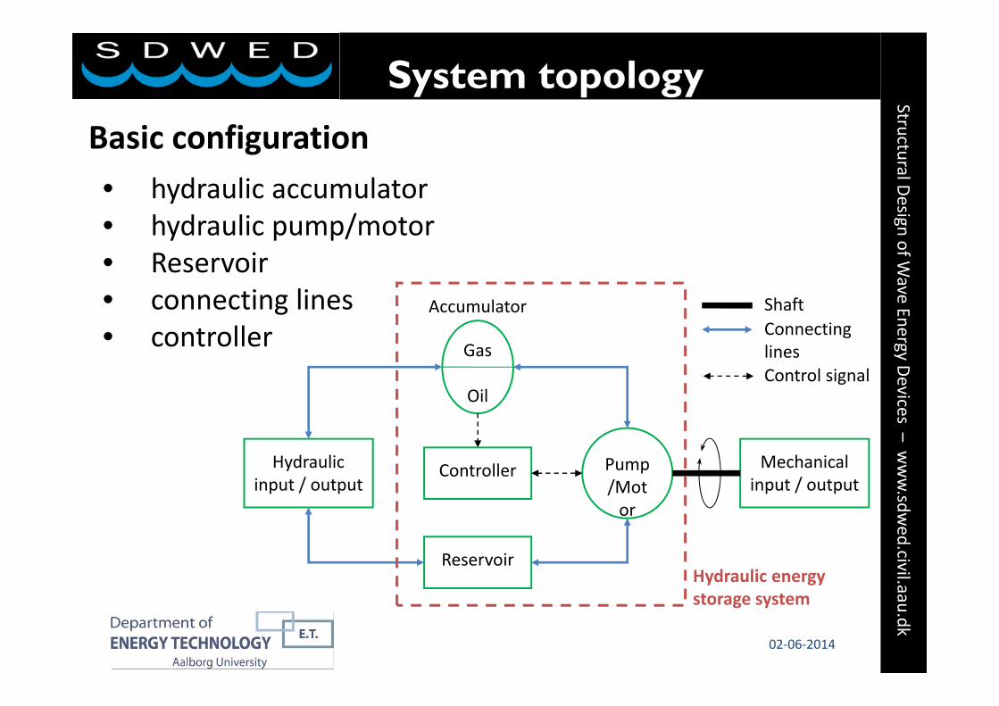
• hydraulic accumulator• hydraulic pump/motor• Reservoir• connecting lines• controller
Basic configuration
System topology
Gas
Oil
Pump/Motor
Reservoir
Controller Mechanicalinput / output
Hydraulicinput / output
ShaftConnecting linesControl signal
Accumulator
Hydraulic energy storage system
Structural Design of Wave Energy Devices –
www.sdw
ed.civil.aau.dk
8 02‐06‐2014
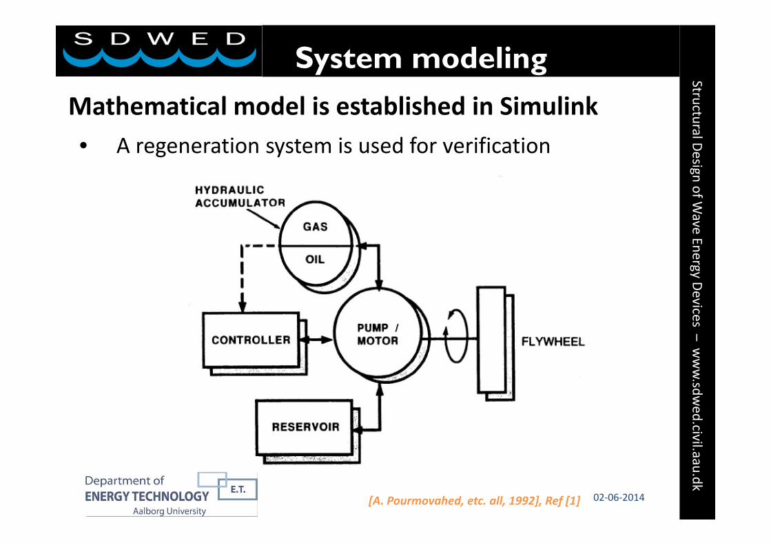
• A regeneration system is used for verification
Mathematical model is established in Simulink
System modeling
[A. Pourmovahed, etc. all, 1992], Ref [1]
Structural Design of Wave Energy Devices –
www.sdw
ed.civil.aau.dk
9 02‐06‐2014
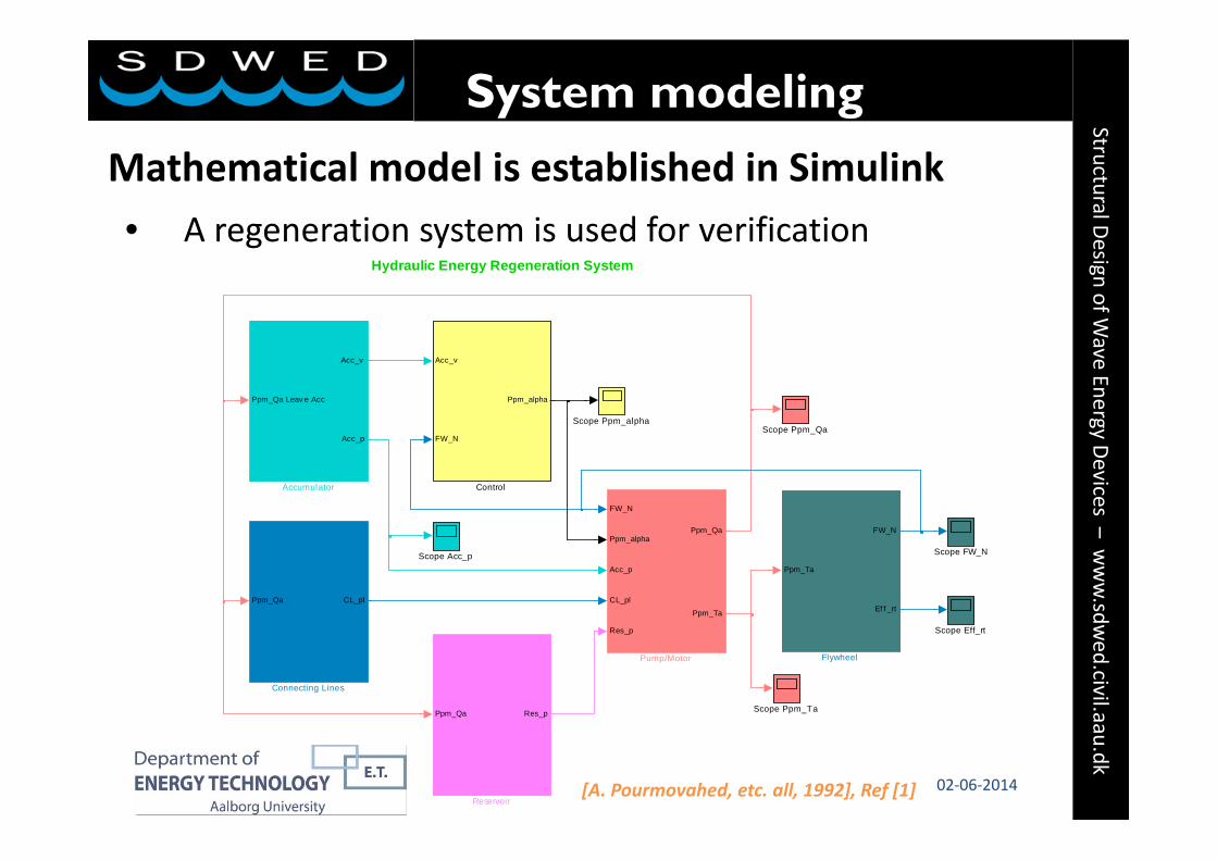
• A regeneration system is used for verification
Mathematical model is established in Simulink
System modeling
Hydraulic Energy Regeneration System
Scope Ppm_alpha
Scope Ppm_Ta
Scope Ppm_Qa
Scope FW_N
Scope Eff_rt
Scope Acc_p
Ppm_Qa Res_p
Reservoir
FW_N
Ppm_alpha
Acc_p
CL_pl
Res_p
Ppm_Qa
Ppm_Ta
Pump/Motor
Ppm_Ta
FW_N
Ef f _rt
Flywheel
Acc_v
FW_N
Ppm_alpha
Control
Ppm_Qa CL_pl
Connecting Lines
Ppm_Qa Leav e Acc
Acc_v
Acc_p
Accumulator
[A. Pourmovahed, etc. all, 1992], Ref [1]
Structural Design of Wave Energy Devices –
www.sdw
ed.civil.aau.dk
10 02‐06‐2014
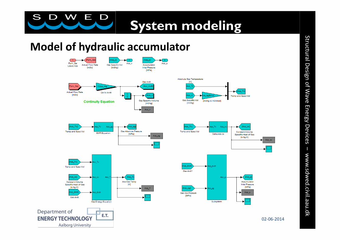
Model of hydraulic accumulator
System modeling

Structural Design of Wave Energy Devices –
www.sdw
ed.civil.aau.dk
11 02‐06‐2014
Simulation and reference results comparison
Verification
0 20 40 60 80 100 1200
200
400
600
800
1000
1200
1400
1600
1800
2000
Time (s)
Flyw
heel
Spe
ed (r
/min
)
P/M Angle = 20 Deg, Cold Oil
0 20 40 60 80 100 1204
6
8
10
12
14
16
18
20
Time (s)G
as P
ress
ure
(MP
a)
P/M Angle = 20 Deg, Cold Oil
0 5 10 15 20-100
-80
-60
-40
-20
0
20
40
60
80
100
Cycle Number, i
Rou
nd-tr
ip E
ffici
ency
, %
P/M Angle = 20 Deg, Cold Oil
[A. Pourmovahed, etc. all, 1992], Ref [2]

Structural Design of Wave Energy Devices –
www.sdw
ed.civil.aau.dk
12 02‐06‐2014
System topology• The excessive wave energy
enters the energy overflow system, where energy storage system is installed
• Hydraulic pump/motor works at motor mode only
• Output power to generator is controlled by adjusting the swivel angle
Case study - WaveStar
[R. H. Hansen, etc. all, 2011], Ref [3]

Structural Design of Wave Energy Devices –
www.sdw
ed.civil.aau.dk
13 02‐06‐2014
System model
Case study - WaveStarHydraulic Energy Storage System
Wave_no
Wave Type1, 2 or 3
Scope Ppm_alpha
Scope Ppm_Ta
Scope Ppm_Qa
Scope Gen_T
Scope Gen_N
Scope Eff_Sys
Scope CC_Qa
Ppm_Qa
CC_Qa
Res_p
Reservoir
FW_N
Ppm_alpha
Acc_p
CL_pl
Res_p
Ppm_Qa
Ppm_Ta
Pump/Motor
Ppm_Ta
Gen_N
Gen_T
Gen_Pin
Electric Generator
Gen_Pin
Cy l_P
CC_P
Whl_Ef f
Sy s_Ef f
Efficiency Calculation
Acc_p
Wav _t
Res_p
Cy l_P
CC_Qa
CC_P
Cylinder and Check Valve
Acc_v
Gen_T
Ppm_alpha
Control
Ppm_Qa CL_pl
Connecting Lines
Ppm_Qa Leav e Acc
CC_Qa
Acc_v
Acc_p
Accumulator

Structural Design of Wave Energy Devices –
www.sdw
ed.civil.aau.dk
14 02‐06‐2014
Work procedure
Case study - WaveStar
910 920 930 940 950 960-1
-0.5
0
x
Fraction of Maximum Unit Capacity
910 920 930 940 950 9600
20
40
60
Time (s)
Sha
ft Pow
er [k
W]
Shaft Power and Hydraulic Input Power
910 920 930 940 950 9600
100
200
300
Time (s)
Hyd
raulic P
ower [k
W]
910 920 930 940 950 9600
0.01
0.02
0.03
0.04
Gas
Volum
e [m
3 ]
Gas Volume, Flow Rate and Pressure
910 920 930 940 950 960-5
0
5
10
15x 10
-3
Time (s)
Flow
Rate [m
3 /s]
910 920 930 940 950 9600
10
20
30
40
Time (s)
Press
ure [M
Pa]
1234 5 6 7
1. Too much input, relief valve open to limit the system pressure to max; swivel angle (capacity) is limited in order to limit the shaft power output;
2. No input, system pressure drops as stored energy is used; no pump capacity limitation;
Structural Design of Wave Energy Devices –
www.sdw
ed.civil.aau.dk
15 02‐06‐2014
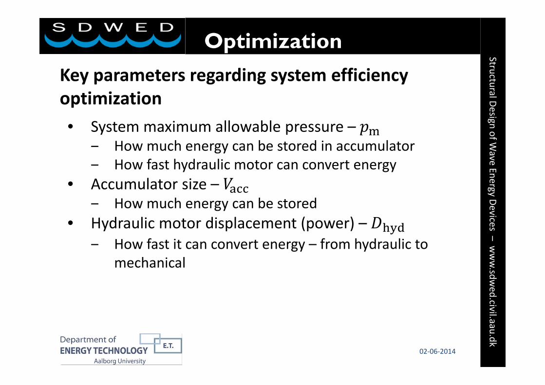
Key parameters regarding system efficiency optimization• System maximum allowable pressure –
‒ How much energy can be stored in accumulator‒ How fast hydraulic motor can convert energy
• Accumulator size –‒ How much energy can be stored
• Hydraulic motor displacement (power) –‒ How fast it can convert energy – from hydraulic to
mechanical
Optimization

Structural Design of Wave Energy Devices –
www.sdw
ed.civil.aau.dk
16 02‐06‐2014
System maximum allowable pressure
Optimization
0100
200300
400 4050
6070
0.7
0.75
0.8
0.85
0.9
0.95
Hydraulic MotorDisplacement [cm3/rev]
System EfficiencyWave 3, 40kW Generator, System Max. Pressure 35MPa
Accumulator MaximumGas Volume [liter] 0
100200
300400 40
5060
70
0.7
0.75
0.8
0.85
0.9
0.95
Hydraulic MotorDisplacement [cm3/rev]
System EfficiencyWave 3, 40kW Generator, System Max. Pressure 45MPa
Accumulator MaximumGas Volume [liter]
0100
200300
400 4050
6070
0.7
0.75
0.8
0.85
0.9
0.95
Hydraulic MotorDisplacement [cm3/rev]
System EfficiencyWave 2, 40kW Generator, System Max. Pressure 35MPa
Accumulator MaximumGas Volume [liter] 0
100200
300400 40
5060
70
0.7
0.75
0.8
0.85
0.9
0.95
Hydraulic MotorDisplacement [cm3/rev]
System EfficiencyWave 2, 40kW Generator, System Max. Pressure 45MPa
Accumulator MaximumGas Volume [liter]
At sea state 3:
• ↑ → ↑
• ↑ → ↑
• ↑ → ↓
At sea state 2:
• ↑ → ↓→ ↓→ ↓
• ↑ → ↓→ ↓→ ↓

Structural Design of Wave Energy Devices –
www.sdw
ed.civil.aau.dk
0100
200300
400 4050
6070
0.7
0.75
0.8
0.85
0.9
0.95
Hydraulic MotorDisplacement [cm3/rev]
System EfficiencyWave 3, 30kW Generator, System Max. Pressure 35MPa
Accumulator MaximumGas Volume [liter] 0
100200
300400 40
5060
70
0.7
0.75
0.8
0.85
0.9
0.95
Hydraulic MotorDisplacement [cm3/rev]
System EfficiencyWave 3, 40kW Generator, System Max. Pressure 35MPa
Accumulator MaximumGas Volume [liter]
0100
200300
400 4050
6070
0.7
0.75
0.8
0.85
0.9
0.95
Hydraulic MotorDisplacement [cm3/rev]
System EfficiencyWave 2, 30kW Generator, System Max. Pressure 35MPa
Accumulator MaximumGas Volume [liter] 0
100200
300400 40
5060
70
0.7
0.75
0.8
0.85
0.9
0.95
Hydraulic MotorDisplacement [cm3/rev]
System EfficiencyWave 2, 40kW Generator, System Max. Pressure 35MPa
Accumulator MaximumGas Volume [liter]
17 02‐06‐2014
Generator rated power
Optimization
At sea state 3:
• ↑ → ↑
• ↑ → ↑
• ↑ → ↑
At sea state 2:
• 30kW is big enough
• At very small , drops
due to waste of energy
Structural Design of Wave Energy Devices –
www.sdw
ed.civil.aau.dk
18 02‐06‐2014
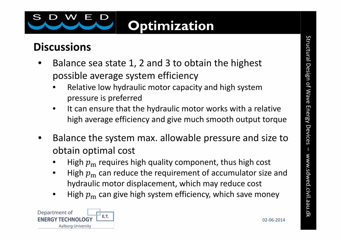
Discussions• Balance sea state 1, 2 and 3 to obtain the highest
possible average system efficiency• Relative low hydraulic motor capacity and high system
pressure is preferred• It can ensure that the hydraulic motor works with a relative
high average efficiency and give much smooth output torque
• Balance the system max. allowable pressure and size to obtain optimal cost• High requires high quality component, thus high cost• High can reduce the requirement of accumulator size and
hydraulic motor displacement, which may reduce cost• High can give high system efficiency, which save money
Optimization
Structural Design of Wave Energy Devices –
www.sdw
ed.civil.aau.dk
19 02‐06‐2014
Summary• The model can be used to analyse the performance of
hydraulic energy storage system, and give reasonable accuracy
• Key parameters regarding system efficiency optimization are found and discussed
• A system efficiency around 85 percent seems to be an attainable theoretical value. In a real system, system efficiency of 80 percent may be practically expected.
Summary
Structural Design of Wave Energy Devices –
www.sdw
ed.civil.aau.dk
20 02‐06‐2014
Reference1. A. Pourmovahed, N. H. Beachley, F. J. Fronczak, “Modeling of a Hydraulic Energy Regeneration
System – Part I: Analytical Treatment”, Journal of Dynamic Systems, Measurement, and Control, vol. 114, pp. 155‐159, Mar. 1992.
2. A. Pourmovahed, N. H. Beachley, F. J. Fronczak, “Modeling of a Hydraulic Energy Regeneration System – Part II: Experimental Program”, Journal of Dynamic Systems, Measurement, and Control, vol. 114, pp. 160‐165, Mar. 1992.
3. R. H. Hansen, T. O. Andersen, and H. C. Pedersen, Model Based Design of Efficient Power Take‐off Systems for Wave Energy Converters, in The 12th Scandinavian International Conference on Fluid Power, May 18‐20, Tampere, Finland, 2011
Funded by
The International Research Alliance
2102‐06‐2014