Embed Size (px)
Citation preview

Spacecraft Structural Dynamics & Loads - A. Calvi 1
This presentation is distributed to the students of the University of Liege
Satellite Engineering Class – November 29, 2010)
This presentation is not for further distribution
Spacecraft Structural Dynamics & Loads An Overview
Adriano Calvi, PhDESA / ESTEC, Noordwijk, The Netherlands

Spacecraft Structural Dynamics & Loads - A. Calvi 2
ForewordForeword
•
This half-day course on “Structural Dynamics and Loads”
intends to present the subject within the broad context of the development of spacecraft structures.
Basic notions as well as some “advanced”
concepts are explained with minimum mathematics
•
The content is the result of the author’s experience acquired through his involvement with research and industrial activities mainly at the European Space Agency and Alenia Spazio
•
The course is specifically tailored for university students

Spacecraft Structural Dynamics & Loads - A. Calvi 3
Specific Objectives of the Presentation
•
To provide a short overview about structural dynamics and its importance in the development of the spacecraft structures (design, analysis & test)
–
To introduce the students to the “logic and criteria”
as regards “dynamics and loads”
•
To point out the importance of some topics such as “modal effective mass”, “dynamic testing”
and “model validation”
often not
addressed in the University Courses•
To show results of some applications (satellites, launchers, etc.)
•
To testify the importance of structural dynamics analysis (and specifically of some numerical methods)

Spacecraft Structural Dynamics & Loads - A. Calvi 4
Spacecraft Structural Dynamics & Loads (1)
•
Introduction–
Preliminary concepts: the launch mechanical environment
–
Requirements for spacecraft structures–
The role of structural dynamics in a space project
•
Dynamic analysis types–
Real eigenvalue
–
Frequency response–
Transient response
–
Shock response–
Random vibration
•
The effective mass concept•
Preliminary design, design load cycles & verification loads cycle
Spacecraft Structural Dynamics & Loads - A. Calvi 5
Spacecraft Structural Dynamics & Loads (2)
•
Payload-launcher Coupled Loads Analysis (CLA)•
Mechanical tests
–
Modal survey test–
Sinusoidal vibration test
–
Acoustic noise test–
Shock test
–
Random vibration test•
Overtesting, “notching”
and sine vibration testing
•
Mathematical model updating and validation•
Summary and conclusive remarks
–
Bibliography

Spacecraft Structural Dynamics & Loads - A. Calvi 6
Preliminary concepts (1)Preliminary concepts (1)
Structural dynamics is the study of structures subjected to a mechanical environment which depends on time and leading to a
movement
•
Excitation transmission types (mechanical & acoustic)•
Type of time functions (sinusoidal, transient, random)
•
Type of frequencies involved (low frequency, broadband)•
Domain of analysis (time domain, frequency domain)
•
Structure representation with a mathematical model (continuous or discrete)

Spacecraft Structural Dynamics & Loads - A. Calvi 7
Preliminary concepts (2)Preliminary concepts (2)•
The parameter most commonly used (in the industry) to “define the motion of a mechanical system”
is the acceleration
•
Typical ranges of acceleration of concern in aerospace structures are from 0.01 g to 10,000 g.
•
Frequency (Hz or rad/s) and “octave”•
Vibroacoustics, pressure (N/m2) and Sound Pressure Level (dB)
•
Random vibration and (acceleration) Power Spectral Density (g2/Hz)•
Shock Response Spectrum
•
Root mean square (rms) = square root of the mean of the sum of all the squares
–
Note 1: the decibel is a tenth of a bel, the logarithm (base 10)
of a power ratio (it is accepted that power is proportional to the square of the rms
of acceleration, velocity, pressure, etc.)
–
Note 2: it must be emphasized that dB in acoustics is not an unit of acoustic pressure but simply a power ratio with respect to a reference pressure which must be stated or clearly implicit

Spacecraft Structural Dynamics & Loads - A. Calvi 8
Example of satellite structural design conceptExample of satellite structural design concept
Spacecraft Structural Dynamics & Loads - A. Calvi 9
AccelerationsAccelerations…… some remarkssome remarks•
The parameter most commonly used (in the industry) to “define the motion of a mechanical system” is the acceleration
•
Good reasons: accelerations are directly related to forces/stresses and “easy”
to specify and measure
•
Some “hidden”
assumptions–
Criteria for equivalent structural damage (e.g. shock response spectra)Note: failures usually happen in the largest stress areas, regardless if they are the largest acceleration areas!
–
Rigid or static determinate junction (e.g. quasi-static loads)•
Important consequences
–
Need for considering the “actual”
(e.g. “test”
or “
flight”) boundary conditions (e.g. for the purpose of “notching”)
–
Need for a “valid”
F.E. model (e.g. to be used for force and stress recovery)
Spacecraft Structural Dynamics & Loads - A. Calvi 10
Mechanical loads are caused by:Mechanical loads are caused by:•
Transportation
•
Rocket Motor Ignition Overpressure•
Lift-off Loads
•
Engine/Motor Generated Acoustic Loads•
Engine/Motor Generated Structure-borne Vibration Loads
•
Engine/Motor Thrust Transients•
Pogo Instability, Solid Motor Pressure Oscillations
•
Wind and Turbulence, Aerodynamic Sources•
Liquid Sloshing in Tanks
•
Stage and Fairing Separation Loads•
Pyrotechnic Induced Loads
•
Manoeuvring Loads•
Flight Operations, Onboard Equipment Operation

Spacecraft Structural Dynamics & Loads - A. Calvi 11
Launch mechanical environmentLaunch mechanical environment
•
Steady state accelerations•
Low frequency vibrations
•
Broad band vibrations–
Random vibrations
–
Acoustic loads•
Shocks
•
Loads (vibrations) are transmitted to the payload (e.g. satellite)through its mechanical interface•
Acoustic loads also directly excite payload surfaces

Spacecraft Structural Dynamics & Loads - A. Calvi 12
““SteadySteady--statestate”” and lowand low--frequency transient accelerationsfrequency transient accelerations

Spacecraft Structural Dynamics & Loads - A. Calvi 13
Acoustic LoadsAcoustic Loads
•
During the lift off and the early phases of the launch an extremely high level of acoustic noise surrounds the payload
•
The principal sources of noise are:–
Engine functioning–
Aerodynamic turbulence
•
Acoustic noise (as pressure waves) impinging on light weight panel-like structures produce high response

Spacecraft Structural Dynamics & Loads - A. Calvi 14
Broadband and high frequency vibrationsBroadband and high frequency vibrations
Broad band random vibrations are produce by:•
Engines functioning
•
Structural response to broad-band acoustic loads•
Aerodynamic turbulent boundary layer
Spacecraft Structural Dynamics & Loads - A. Calvi 15
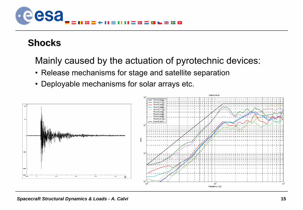
ShocksShocks
Mainly caused by the actuation of pyrotechnic devices:•
Release mechanisms for stage and satellite separation
•
Deployable mechanisms for solar arrays etc.

Spacecraft Structural Dynamics & Loads - A. Calvi 16
Static and dynamic environment specification (typical ranges)Static and dynamic environment specification (typical ranges)

Spacecraft Structural Dynamics & Loads - A. Calvi 17
QuasiQuasi--Static Loads (accelerations)Static Loads (accelerations)•
“Loads independent of time or which vary slowly, so that the dynamic response of the structure is not significant”
(ECSS-E-ST-32). Note: this is
the definition of a quasi-static event!•
“Combination of static and low frequency loads into an equivalent
static
load specified for design purposes as C.o.G. acceleration”
(e.g. NASA RP- 1403, NASA-HDBK-7004). Note: this definition is fully adequate for the
design of the spacecraft primary structure. For the design of components the contribution of the high frequency loads, if relevant, is included as well!
•
CONCLUSION: quasi static loading means under steady-state accelerations
(unchanging applied force balanced by inertia loads). For
design purposes (e.g. derivation of design limit loads, selection of the fasteners, etc.), the quasi-static loads are normally calculated by combining both static and dynamic load contributions. In this context the quasi static loads are equivalent to (or interpreted by the designer
as)
static loads, typically expressed as equivalent accelerations at the C.o.G.
Spacecraft Structural Dynamics & Loads - A. Calvi 18
Typical Requirements for Spacecraft Structures•
Strength
•
Structural life•
Structural response
•
Stiffness•
Damping
•
Mass Properties•
Dynamic Envelope
•
Positional Stability•
Mechanical Interface
•
Basic requirement: the structure shall support the payload and spacecraft subsystems with enough strength and stiffness to preclude any failure (rupture, collapse, or detrimental deformation) that may keep them from working successfully.

Spacecraft Structural Dynamics & Loads - A. Calvi 19
Requirements evolutionRequirements evolution

Spacecraft Structural Dynamics & Loads - A. Calvi 20
Design requirements and verificationDesign requirements and verification

Spacecraft Structural Dynamics & Loads - A. Calvi 21
Examples of (Mechanical) Requirements (1)•
The satellite shall be compatible with 2 launchers (potential candidates: VEGA, Soyuz in CSG, Rockot, Dnepr)...
•
The satellite and all its units shall withstand applied loads due to the mechanical environments to which they are exposed during the service-life…
•
Design Loads shall be derived by multiplication of the Limit Loads by a design factor equal to 1.25 (i.e. DL= 1.25 x LL)
•
The structure shall withstand the worst design loads without failing or exhibiting permanent deformations.
•
Buckling is not allowed.•
The natural frequencies of the structure shall be within adequate bandwidths to prevent dynamic coupling with major excitation frequencies…
•
The spacecraft structure shall provide the mounting interface to
the launch vehicle and comply with the launcher interface requirements.

Spacecraft Structural Dynamics & Loads - A. Calvi 22
Examples of (Mechanical) Requirements (2)•
All the Finite Element Models (FEM) prepared to support the mechanical verification activities at subsystem and satellite level shall be delivered in NASTRAN format
•
The FEM of the spacecraft in its launch configuration shall be detailed enough to ensure an appropriate derivation and verification of the design loads and of the modal response of the various structural elements of the satellite up to 140 Hz
•
A reduced FEM of the entire spacecraft correlated with the detailed FEM shall be delivered for the Launcher Coupled Loads Analysis (CLA)…
•
The satellite FEMs
shall be correlated against the results of modal survey tests carried out at complete spacecraft level, and at component level
for units above
50 kg…•
The structural model of the satellite shall pass successfully qualification sine vibration Test.
•
The flight satellite shall pass successfully acceptance sine vibration test.

Spacecraft Structural Dynamics & Loads - A. Calvi 23
Spacecraft stiffness requirements for different launchersSpacecraft stiffness requirements for different launchers
Launch vehicle manuals specify minimum values for the payload natural (fundamental) frequency of vibration in order to avoid dynamic coupling between low frequency dynamics of the launch vehicle and payload modes

Spacecraft Structural Dynamics & Loads - A. Calvi 24
The Role of Structural Dynamics in a Space ProjectThe Role of Structural Dynamics in a Space Project•
Mechanical environment definition (structural response and loads
identification by analysis and test)–
Launcher/Payload coupled loads analysis–
Random vibration and vibroacoustic analyses–
Jitter analysis–
Test predictions (e.g. sine test by frequency response analysis)–
Test evaluations (sine, acoustic noise…)–
Input to structural life analysis (e.g. generation of the loading spectrum)–
…•
Structural identification (by analysis and test)
–
Modal analysis–
Modal survey test and experimental modal analysis–
Mathematical model updating and validation
•
Design qualification and flight product acceptance–
Qualification and Acceptance tests (sine, random, acoustic noise, shock)

Spacecraft Structural Dynamics & Loads - A. Calvi 25
Spacecraft Structural Dynamics & Loads (1)
•
Introduction–
Preliminary concepts: the launch mechanical environment
–
Requirements for spacecraft structures–
The role of structural dynamics in a space project
•
Dynamic analysis types–
Real eigenvalue
–
Frequency response–
Transient response
–
Shock response–
Random vibration
•
The effective mass concept•
Preliminary design, design load cycles & verification loads cycle

Spacecraft Structural Dynamics & Loads - A. Calvi 26
Dynamic analysis typesDynamic analysis types•
Real eigenvalue analysis (undamped free vibrations)
–
Modal parameter identification, etc.•
Linear frequency response analysis (steady-state response of linear structures to loads that vary as a function of frequency)
–
Sine test prediction, transfer functions calculation, LV/SC CLA etc.•
Linear transient response analysis (response of linear structures to loads that vary as a function of time).
–
LV/SC CLA, base drive analysis, jitter analysis, etc.•
“Shock” response spectrum analysis
–
Specification of equivalent environments (e.g. equivalent sine input),–
Shock test specifications, etc.
•
Vibro-acoustics (FEM/BEM, SEA) & Random vibration analysis–
Vibro-acoustic test prediction & random vibration environment definition
–
Loads analysis for base-driven random vibration

Spacecraft Structural Dynamics & Loads - A. Calvi 27
Reasons to compute normal modes (real eigenvalue analysis)Reasons to compute normal modes (real eigenvalue analysis)•
To verify stiffness requirements
•
To assess the dynamic interaction between a component and its supporting structure
•
To guide experiments (e.g. modal survey test)•
To validate computational models (e.g. test/analysis correlation)
•
As pre-requisite for subsequent dynamic analyses•
To evaluate design changes
•
Mathematical model quality check (model verification)•
Numerical methods: Lanczos,…
Spacecraft Structural Dynamics & Loads - A. Calvi 28
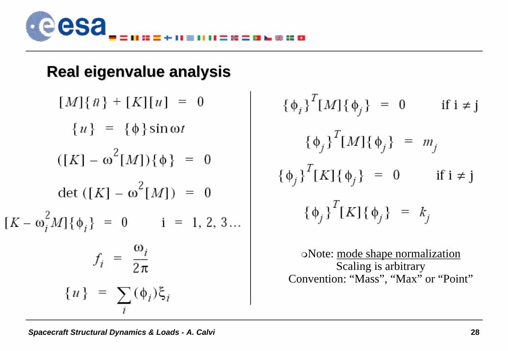
Real eigenvalue analysisReal eigenvalue analysis
Note: mode shape normalizationScaling is arbitrary
Convention: “Mass”, “Max” or “Point”

Spacecraft Structural Dynamics & Loads - A. Calvi 29
Mode shapesMode shapes
Cantilever beam
Simply supported beam
Spacecraft Structural Dynamics & Loads - A. Calvi 30
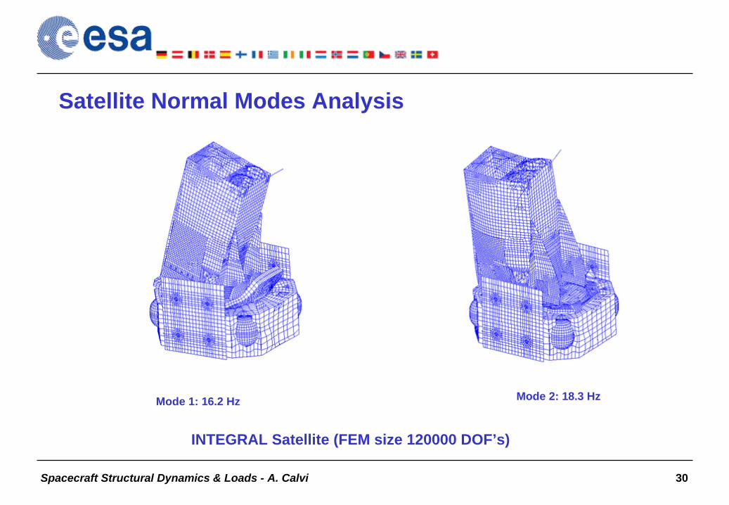
Satellite Normal Modes Analysis
Mode 1: 16.2 Hz Mode 2: 18.3 Hz
INTEGRAL Satellite (FEM size 120000 DOF’s)

Spacecraft Structural Dynamics & Loads - A. Calvi 31
Frequency Response AnalysisFrequency Response Analysis
•
Used to compute structural response to steady-state harmonic excitation
•
The excitation is explicitly defined in the frequency domain•
Forces can be in the form of applied forces and/or enforced motions
•
Two different numerical methods: direct and modal•
Damped forced vibration equation of motion with harmonic excitation:
Spacecraft Structural Dynamics & Loads - A. Calvi 32
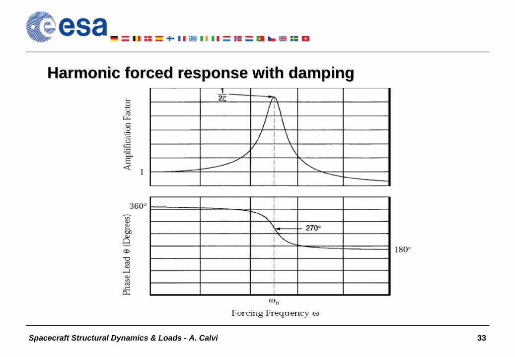
Frequency response considerationsFrequency response considerations
•
If the maximum excitation frequency is much less than the lowest resonant frequency of the system, a static analysis is probably
sufficient•
Undamped or very lightly damped structures exhibit large dynamic
responses for excitation frequencies near natural frequencies (resonant frequencies)
•
Use a fine enough frequency step size (Δf) to adequately predict peak response.
•
Smaller frequency spacing should be used in regions near resonant frequencies, and larger frequency step sizes should be used in regions away from resonant frequencies
Spacecraft Structural Dynamics & Loads - A. Calvi 33
Harmonic forced response with dampingHarmonic forced response with damping

Spacecraft Structural Dynamics & Loads - A. Calvi 34
Transient Response AnalysisTransient Response Analysis
•
Purpose is to compute the behaviour of a structure subjected to time- varying excitation
•
The transient excitation is explicitly defined in the time domain•
Forces can be in the form of applied forces and/or enforced motions
•
The important results obtained from a transient analysis are typically displacements, velocities, and accelerations of grid points, and
forces and stresses in elements•
Two different numerical methods: direct
(e.g. Newmark) and modal
(e.g. Lanczos
+ Duhamel’s integral or Newmark)•
Dynamic equation of motion:

Spacecraft Structural Dynamics & Loads - A. Calvi 35
Modal Transient Response AnalysisModal Transient Response Analysis
Spacecraft Structural Dynamics & Loads - A. Calvi 36
Transient response considerationsTransient response considerations
•
The integration time step must be small enough to represent accurately the variation in the loading
•
The integration time step must also be small enough to represent
the maximum frequency of interest (“cut-off frequency”)
•
The cost of integration is directly proportional to the number of time steps•
Very sharp spikes in a loading function induce a high-frequency transient response. If the high-frequency transient response is of primary importance in an analysis, a very small integration time step must be used
•
The loading function must accurately describe the spatial and temporal distribution of the dynamic load
Spacecraft Structural Dynamics & Loads - A. Calvi 37
““ShockShock”” response spectrum (and analysis)response spectrum (and analysis)•
Response spectrum analysis is an approximate method of computing the peak response of a transient excitation
applied to a
structure or component•
There are two parts to response spectrum analysis: (1) generation of the spectrum and (2) use of the spectrum for dynamic response
such as stress analysis
•
Note 1: the “part (2)”
of the response spectrum analysis has a limited use in structural dynamics of spacecraft (e.g. preliminary design) since the accuracy of the method may be questionable
•
Note 2: the term “shock”
can be misleading (not always a “physical shock”, i.e. an environment of a “short duration”, is involved. It would be better to use “response spectrum”)

Spacecraft Structural Dynamics & Loads - A. Calvi 38
Generation of a response spectrum (1)Generation of a response spectrum (1)
Spacecraft Structural Dynamics & Loads - A. Calvi 39
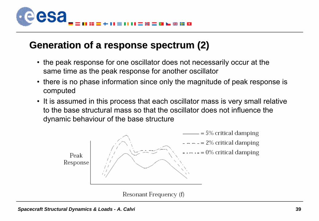
Generation of a response spectrum (2)Generation of a response spectrum (2)•
the peak response for one oscillator does not necessarily occur at the same time as the peak response for another oscillator
•
there is no phase information since only the magnitude of peak response is computed
•
It is assumed in this process that each oscillator mass is very small relative to the base structural mass so that the oscillator does not influence the dynamic behaviour of the base structure

Spacecraft Structural Dynamics & Loads - A. Calvi 40
Shock Response Spectrum. Some remarksShock Response Spectrum. Some remarks•
The 1-DOF system is used as reference structure (since the simplest) for the characterization of environments (i.e. quantification of the severity → equivalent environments can be specified)
•
In practice, the criterion used for the severity is the maximum response which occurs on the structure
(note: another criterion
relates to the concept of fatigue damage…)•
A risk in comparing two excitations of different nature is in the influence of damping on the results (e.g. maxima are proportional to Q for sine excitation and variable for transient excitation!)
•
The absolute acceleration spectrum
is used, which provides information about the maximum internal forces and stresses
•
The shock spectrum is a transformation of the time history which
is not reversible (contrary to Fourier transform)

Spacecraft Structural Dynamics & Loads - A. Calvi 41
Shock Response SpectrumShock Response Spectrum
(A) is the shock spectrum of a terminal peak sawtooth (B) of 500 G peak amplitude and 0.4 millisecond duration

Spacecraft Structural Dynamics & Loads - A. Calvi 42
Random vibration (analysis)Random vibration (analysis)•
Random vibration is vibration that can be described only in a statistical sense
•
The instantaneous magnitude is not known at any given time; rather, the magnitude is expressed in terms of its statistical properties (such as mean value, standard deviation, and probability of exceeding a certain value)
•
Examples of random vibration include earthquake ground motion, wind pressure fluctuations on aircraft, and acoustic excitation due to rocket and jet engine noise
•
These random excitations are usually described in terms of a power spectral density (PSD) function
•
Note: in structural dynamics of spacecraft, the random vibration analysis is often performed with simplified techniques (e.g. based on “Miles’
equation”
+ effective modal mass models)

Spacecraft Structural Dynamics & Loads - A. Calvi 43
Random noise with normal amplitude distributionRandom noise with normal amplitude distribution

Spacecraft Structural Dynamics & Loads - A. Calvi 44
Power Spectral Density (conceptual model)Power Spectral Density (conceptual model)

Spacecraft Structural Dynamics & Loads - A. Calvi 45
Sound Pressure Level (conceptual model)Sound Pressure Level (conceptual model)

Spacecraft Structural Dynamics & Loads - A. Calvi 46
Spacecraft Structural Dynamics & Loads (1)
•
Introduction–
Preliminary concepts: the launch mechanical environment
–
Requirements for spacecraft structures–
The role of structural dynamics in a space project
•
Dynamic analysis types–
Real eigenvalue
–
Frequency response–
Transient response
–
Shock response–
Random vibration
•
The effective mass concept•
Preliminary design, design load cycles & verification loads cycle
Spacecraft Structural Dynamics & Loads - A. Calvi 47
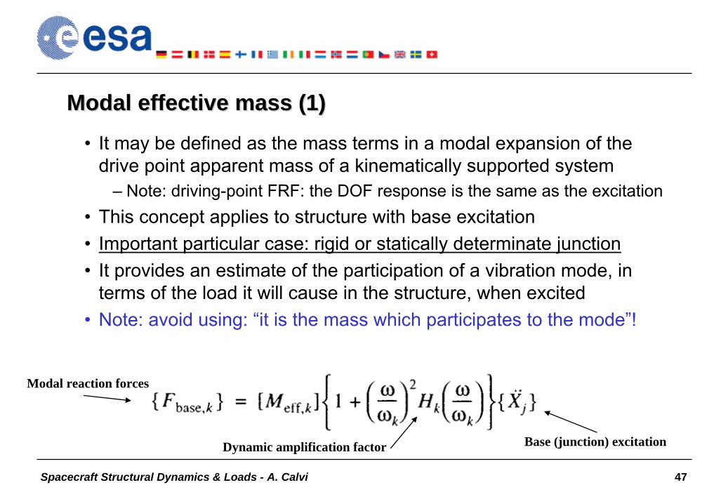
Modal effective mass (1)Modal effective mass (1)
•
It may be defined as the mass terms in a modal expansion of the drive point apparent mass of a kinematically
supported system
–
Note: driving-point FRF: the DOF response is the same as the excitation•
This concept applies to structure with base excitation
•
Important particular case: rigid or statically determinate junction•
It provides an estimate of the participation of a vibration mode, in terms of the load it will cause in the structure, when excited
•
Note: avoid using: “it is the mass which participates to the mode”!
Dynamic amplification factor
Modal reaction forces
Base (junction) excitation

Spacecraft Structural Dynamics & Loads - A. Calvi 48
Modal effective mass (2)Modal effective mass (2)
•
The effective mass matrix can be calculated either by the “modal participation factors”
or by using the modal interface forces
•
Normally only the values on the leading diagonal of the modal effective mass matrix are considered and expressed in percentage
of the structure rigid body properties (total mass and second moments of inertia)
•
The effective mass characterises the mode and it is independent from the eigenvector normalisation
Gen. mass
Resultant of modal interface forces
i-th mode Rigid body modes
Modal participation factorsEffective mass
Eigenvector max value

Spacecraft Structural Dynamics & Loads - A. Calvi 49
Modal effective mass (3)Modal effective mass (3)
•
For the complete set of modes the summation of the modal effective mass is equal to the rigid body mass
•
Contributions of each individual mode to the total effective mass can be used as a criterion to classify the modes
(global or local)
and an indicator of the importance of that mode, i.e. an indication of the magnitude of participation in the loads analysis
•
It can be used to construct a list of important modes for the test/analysis correlation and it is a significant correlation parameter
•
It can be used to create simplified mathematical models
(equivalent models with respect to the junction)

Spacecraft Structural Dynamics & Loads - A. Calvi 50
Example of Effective Mass table (MPLM test and FE model)

Spacecraft Structural Dynamics & Loads - A. Calvi 51
Spacecraft Structural Dynamics & Loads (1)
•
Introduction–
Preliminary concepts: the launch mechanical environment
–
Requirements for spacecraft structures–
The role of structural dynamics in a space project
•
Dynamic analysis types–
Real eigenvalue
–
Frequency response–
Transient response
–
Shock response–
Random vibration
•
The effective mass concept•
Preliminary design, design load cycles & verification loads cycle

Spacecraft Structural Dynamics & Loads - A. Calvi 52
A5 Typical Sequence of eventsA5 Typical Sequence of events

Spacecraft Structural Dynamics & Loads - A. Calvi 53
A5 Typical Longitudinal Static AccelerationA5 Typical Longitudinal Static Acceleration

Spacecraft Structural Dynamics & Loads - A. Calvi 54
Sources of Structural Loadings (Launch)Sources of Structural Loadings (Launch)
Axial-Acceleration Profile for the Rockot Launch Vehicle
g8
7
6
5
4
32
1
0t, s150 200 250 300100500
0 0.1 0.2 0.3 0.4 0.5 0.6 0.7 0.8 0.9 1-20
-10
0
10
20
30
40
50
60
70
80
acce
lera
tion
[m/s
2 ]
t [s]

Spacecraft Structural Dynamics & Loads - A. Calvi 55
Axial Acceleration at Launcher/Satellite Interface (Engines Cut-off)
0 0.1 0.2 0.3 0.4 0.5 0.6 0.7 0.8 0.9 1-20
-10
0
10
20
30
40
50
60
70
80
acce
lera
tion
[m/s
2 ]
t [s]

Spacecraft Structural Dynamics & Loads - A. Calvi 56
Load Factors for Preliminary Design (Ariane 5)Load Factors for Preliminary Design (Ariane 5)

Spacecraft Structural Dynamics & Loads - A. Calvi 57
QuasiQuasi--static loads for different launchersstatic loads for different launchers

Spacecraft Structural Dynamics & Loads - A. Calvi 58
QuasiQuasi--Static Flight Limit loads for Dnepr and SoyuzStatic Flight Limit loads for Dnepr and Soyuz

Spacecraft Structural Dynamics & Loads - A. Calvi 59
Example of Physical (and Modal) Mass Acceleration Curve for preliminary design of payload hardware or equipment items
100
10
11 10 100 1000
Physical
Modal
Effective Mass, kg
Dyn
amic
Res
pons
e A
ccel
erat
ion,
g

Spacecraft Structural Dynamics & Loads - A. Calvi 60
Load Combination Criteria for Components (International Space Station Program)

Spacecraft Structural Dynamics & Loads - A. Calvi 61
Loads and Factors
Expendable launch vehicles,pressurized hardware and manned system Test Logic
Common Design LogicSatellitesTest Logic
Limit Loads - LL
Design Limit LoadsDLL
x Coef. A
DYL
x Coef. B
DUL
x Coef. C
x KQ x KA
QLAL
x KQ x KA
QL
AL
Incr
easi
ng L
oad
Leve
lECSS E-ST-32-10

Spacecraft Structural Dynamics & Loads - A. Calvi 62
Some definitionsSome definitions•
Design:
–
The process used to generate the set information describing the essential characteristics of a product (ECSS-P-001A)
–
Design means developing requirements, identifying options, doing analyses and trade studies, and defining a product in enough detail so
it can be built (T. P. Sarafin)•
Verification:
–
Confirmation by examination and provision of objective evidence that specified requirements have been fulfilled (ISO 8402:1994)
–
Verification means providing confidence through disciplined steps that a product will do what it is supposed to do (T. P. Sarafin)
•
Note: we can “prove”
that the spacecraft satisfies the measurable criteria we have defined, but we cannot “prove”
a space mission will be successful

Spacecraft Structural Dynamics & Loads - A. Calvi 63
Design Loads CyclesDesign Loads Cycles
A load cycle is the process of:
•
Generating and combining math models for a proposed design•
Assembling and developing forcing functions, load factors, etc. to simulate the critical loading environment
•
Calculating design loads and displacements for all significant ground, launch and mission events
•
Assessing the results to identify design modifications or risks•
Then, if necessary, modifying the design accordingly or choosing
to
accept the risk

Spacecraft Structural Dynamics & Loads - A. Calvi 64
Design loads cycle processDesign loads cycle process
Spacecraft Structural Dynamics & Loads - A. Calvi 65
Final VerificationFinal Verification
Consist of:
•
Making sure all requirements are satisfied (“compliance”)
•
Validating the methods and assumptions used to satisfy requirements
•
Assessing risks

Spacecraft Structural Dynamics & Loads - A. Calvi 66
Final Verification (crucial points)Final Verification (crucial points)
•
To perform a Verification Loads Cycle for structures designed and tested to predicted loads
–
Finite element models correlation with the results of modal and static testing
–
Loads prediction with the current forcing functions–
Compliance with analysis criteria (e.g. MOS>0)
•
To make sure the random-vibration environments used to qualify components were high enough (based on data collected during the spacecraft acoustic test)
Note: in the verification loads cycle instead of identifying required design changes (design loads cycle) the adequacy of the structure that has already been built and tested is assessed

Spacecraft Structural Dynamics & Loads - A. Calvi 67
Criteria for Assessing Verification Loads (strength)Criteria for Assessing Verification Loads (strength)
•
Analysis: margins of safety must me greater that or equal to zero
•
Test: Structures qualified by static or sinusoidal testing–
Test loads or stresses “as predicted”
(test-verified math model and test
conditions) are compared with the total predicted loads during the mission
(including flying transients, acoustics, random vibration,
pressure, thermal effects and preloads)
•
Test: Structures qualified by acoustic or random vibration testing–
Test environments are compared with random-vibration environments derived from system-level acoustic testing
Spacecraft Structural Dynamics & Loads - A. Calvi 68
Spacecraft Structural Dynamics & Loads (2)
•
Payload-launcher Coupled Loads Analysis (CLA)•
Mechanical tests
–
Modal survey test–
Sinusoidal vibration test
–
Acoustic noise test–
Shock test
–
Random vibration test•
Overtesting, “notching”
and sine vibration testing
•
Mathematical model updating and validation•
Summary and conclusive remarks
–
Bibliography

Spacecraft Structural Dynamics & Loads - A. Calvi 69
Launcher / Satellite C.L.A.
Mode 18: 2.93 Hz Mode 53: 16.9 Hz
A5 / Satellite Recovered System Mode shapes
•
CLA: simulation of the structural response to low frequency mechanical environment
•
Main Objective: to calculate the loads on the satellite caused by the launch transients (lift-
off, transonic, aerodynamic gust, separation of SRBs…)
•
Loads (in this context): set of internal forces, displacements and accelerations that characterise structural response to the applied forces
•
Effects included in the forcing functions : thrust built-up, engine shut-down/burnout, gravity, aerodynamic loads (gust), separation of boosters, etc.

Spacecraft Structural Dynamics & Loads - A. Calvi 70
Ariane-5 Dynamic Mathematical ModelPAYLOAD
UPPER COMPOSITE
EAP+EAP-
EPC
–
Dynamic effects up to about 100 Hz–
3D FE models of EPC, EAP, UC
–
Dynamic Reduction using Craig-Bampton
formulation–
Incompressible or compressible fluids models for liquid propellants
–
Structure/fluid interaction–
Nearly incompressible SRB solid propellant modeling
–
Pressure and stress effects on launcher stiffness–
SRB propellant and DIAS structural damping
–
Non-linear launch table effects

Spacecraft Structural Dynamics & Loads - A. Calvi 71
Sizing flight events (CLA with VEGA Launcher)Sizing flight events (CLA with VEGA Launcher)
1. Lift-off (P80 Ignition and Blastwave)
2. Mach1/QMAX Gust
3. P80 Pressure Oscillations
4. Z23 Ignition
5. Z23 Pressure Oscillations
6. Z9 Ignition

Spacecraft Structural Dynamics & Loads - A. Calvi 72
CLA OutputCLA Output•
LV-SC interface accelerations
–
Equivalent sine spectrum
•
LV-SC interface forces–
Equivalent accelerations at CoG
•
Internal responses–
Accelerations,–
Displacements–
Forces–
Stresses–
…

Spacecraft Structural Dynamics & Loads - A. Calvi 73
Payload / STS CLAPayload / STS CLA
Lift-off Force Resultant in X [lbf]
Lift-offMain Fitting
I/F ForceX Dir. [N]
Lift-offMain Fitting
I/F ForceZ Dir. [N]
Lift-offKeel Fitting
I/F ForceY Dir. [N]

Spacecraft Structural Dynamics & Loads - A. Calvi 74
Spacecraft Structural Dynamics & Loads (2)
•
Payload-launcher Coupled Loads Analysis (CLA)•
Mechanical tests
–
Modal survey test–
Sinusoidal vibration test
–
Acoustic noise test–
Shock test
–
Random vibration test•
Overtesting, “notching”
and sine vibration testing
•
Mathematical model updating and validation•
Summary and conclusive remarks
–
Bibliography

Spacecraft Structural Dynamics & Loads - A. Calvi 75
Testing techniques Testing techniques –– Introduction (1)Introduction (1)
•
Without testing, an analysis can give completely incorrect results•
Without the analysis, the tests can represent only a very limited reality
•
Two types of tests according to the objectives to be reached:–
Simulation tests for structure qualification or acceptance
–
Identification tests (a.k.a. analysis-validation tests) for structure identification (the objective is to determine the dynamic characteristics of the tested structure in order to “update”
the mathematical model)
•
Note: identification and simulation tests are generally completely dissociated. In certain cases (e.g. spacecraft sine test) it is technically possible to perform them using the same test facility

Spacecraft Structural Dynamics & Loads - A. Calvi 76
Testing techniques Testing techniques –– Introduction (2)Introduction (2)
•
Generation of mechanical environment–
Small shakers (with flexible rod; electrodynamic)
–
Large shakers (generally used to impose motion at the base)•
Electrodynamic shaker•
Hydraulic jack shaker–
Shock machines (pyrotechnic generators and impact machines)
–
Noise generators + reverberant acoustic chamber (homogeneous and diffuse field)
•
Measurements–
Force sensors, calibrated strain gauges
–
Accelerometers, velocity or displacement sensors
Spacecraft Structural Dynamics & Loads - A. Calvi 77
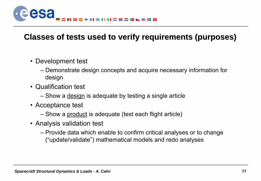
Classes of tests used to verify requirements (purposes)Classes of tests used to verify requirements (purposes)
•
Development test–
Demonstrate design concepts and acquire necessary information for design
•
Qualification test–
Show a design
is adequate by testing a single article
•
Acceptance test–
Show a product
is adequate (test each flight article)
•
Analysis validation test–
Provide data which enable to confirm critical analyses or to change (“update/validate”) mathematical models and redo analyses
Spacecraft Structural Dynamics & Loads - A. Calvi 78
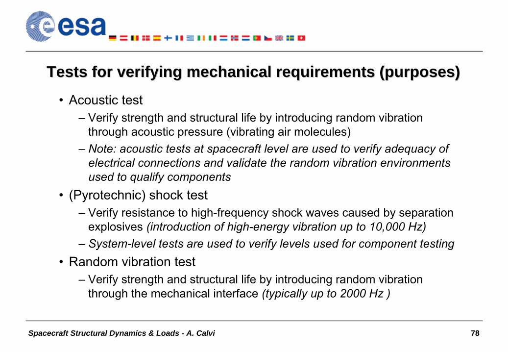
Tests for verifying mechanical requirements (purposes)Tests for verifying mechanical requirements (purposes)
•
Acoustic test–
Verify strength and structural life by introducing random vibration through acoustic pressure (vibrating air molecules)
–
Note: acoustic tests at spacecraft level are used to verify adequacy of electrical connections and validate the random vibration environments used to qualify components
•
(Pyrotechnic) shock test–
Verify resistance to high-frequency shock waves caused by separation explosives (introduction of high-energy vibration up to 10,000 Hz)
–
System-level tests are used to verify levels used for component testing•
Random vibration test
–
Verify strength and structural life by introducing random vibration through the mechanical interface (typically up to 2000 Hz )
Spacecraft Structural Dynamics & Loads - A. Calvi 79
Tests for verifying mechanical requirements (purposes)Tests for verifying mechanical requirements (purposes)
•
Sinusoidal vibration test–
Verify strength for structures that would not be adequately tested in random vibration or acoustic testing
–
Note 1: cyclic loads at varying frequencies are applied to excite the structure modes of vibration
–
Note 2: sinusoidal vibration testing at low levels are performed to verify natural frequencies
–
Note 3: the acquired data can be used for further processing (e.g. experimental modal analysis)
–
Note 4: this may seem like an environmental test, but it is not. Responses are monitored and input forces are reduced as necessary (“notching”) to make sure the target responses or member loads are not exceeded.
Spacecraft Structural Dynamics & Loads - A. Calvi 80
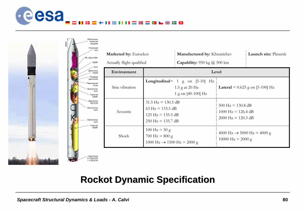
RockotRockot Dynamic SpecificationDynamic Specification
Marketed by: Eurockot
Actually flight qualified
Manufactured by: Khrunichev
Capability: 950 kg @ 500 km
Launch site: Plesetsk
Environment Level
Sine vibration Longitudinal= 1 g on [5-10] Hz 1.5 g at 20 Hz 1 g on [40-100] Hz
Lateral = 0.625 g on [5-100] Hz
Acoustic
31.5 Hz = 130.5 dB 63 Hz = 133.5 dB 125 Hz = 135.5 dB 250 Hz = 135.7 dB
500 Hz = 130.8 dB 1000 Hz = 126.4 dB 2000 Hz = 120.3 dB
Shock 100 Hz = 50 g 700 Hz = 800 g 1000 Hz 1500 Hz = 2000 g
4000 Hz 5000 Hz = 4000 g 10000 Hz = 2000 g
Spacecraft Structural Dynamics & Loads - A. Calvi 81
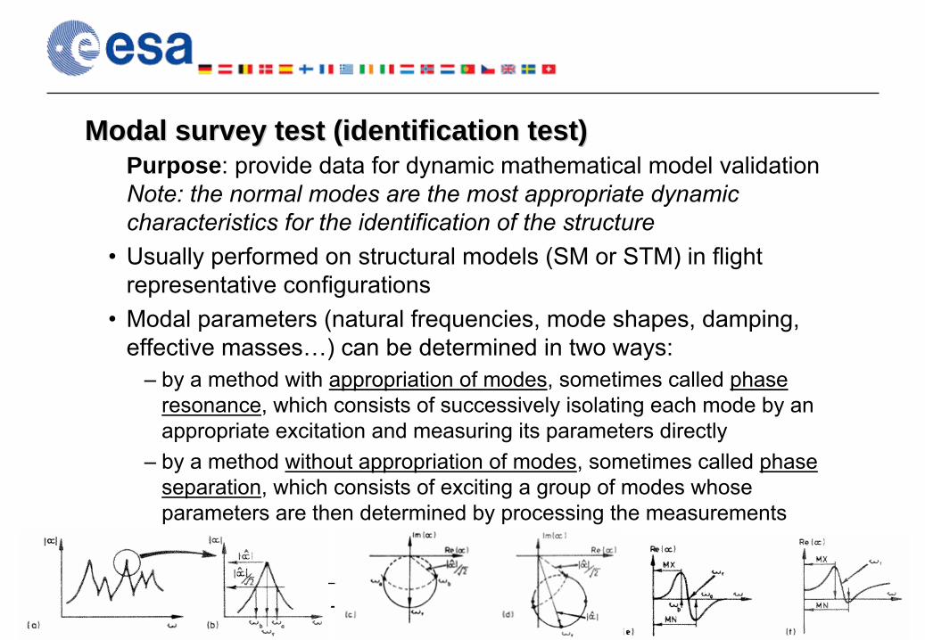
Modal survey test (identification test)Modal survey test (identification test)Purpose: provide data for dynamic mathematical model validation Note: the normal modes are the most appropriate dynamic characteristics for the identification of the structure
•
Usually performed on structural models (SM or STM) in flight representative configurations
•
Modal parameters (natural frequencies, mode shapes, damping, effective masses…) can be determined in two ways:
–
by a method with appropriation of modes, sometimes called phase resonance, which consists of successively isolating each mode by an appropriate excitation and measuring its parameters directly
–
by a method without appropriation of modes, sometimes called phase separation, which consists of exciting a group of modes whose parameters are then determined by processing the measurements

Spacecraft Structural Dynamics & Loads - A. Calvi 82
Different ways to get modal data from testsDifferent ways to get modal data from tests
•
Hammer test
•
Vibration test data analysis
•
Dedicated FRF measurement & modal analysis
•
Full scale modal survey with mode tuningIncr
easi
ng e
ffor
t
Dat
a co
nsis
tenc
y

Spacecraft Structural Dynamics & Loads - A. Calvi 83
Modal Survey Test vs. Modal Data extracted from the Sine Vibration Test
•
Modal Survey:–
requires more effort (financial and time)
–
provides results with higher quality
•
Modal Data from Sine Vibration:–
easy access / no additional test necessary
–
less quality due to negative effects from vibration•
fixtures / facility tables not indefinitely stiff•
higher sweep rate (brings along effects like beating or control instabilities)

Spacecraft Structural Dynamics & Loads - A. Calvi 84
Ariane 5 Ariane 5 -- Sine excitation at spacecraft base (Sine excitation at spacecraft base (sine-equivalent dynamics)
Spacecraft Structural Dynamics & Loads - A. Calvi 85
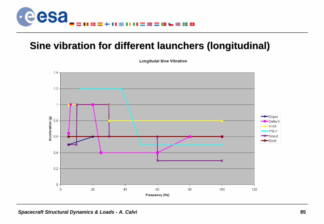
Sine vibration for different launchers (longitudinal)Sine vibration for different launchers (longitudinal)

Spacecraft Structural Dynamics & Loads - A. Calvi 86
Sine vibration for different launchers (lateral)Sine vibration for different launchers (lateral)

Spacecraft Structural Dynamics & Loads - A. Calvi 87
Test Set-up for Satellite Vibration Tests
Spacecraft Structural Dynamics & Loads - A. Calvi 88
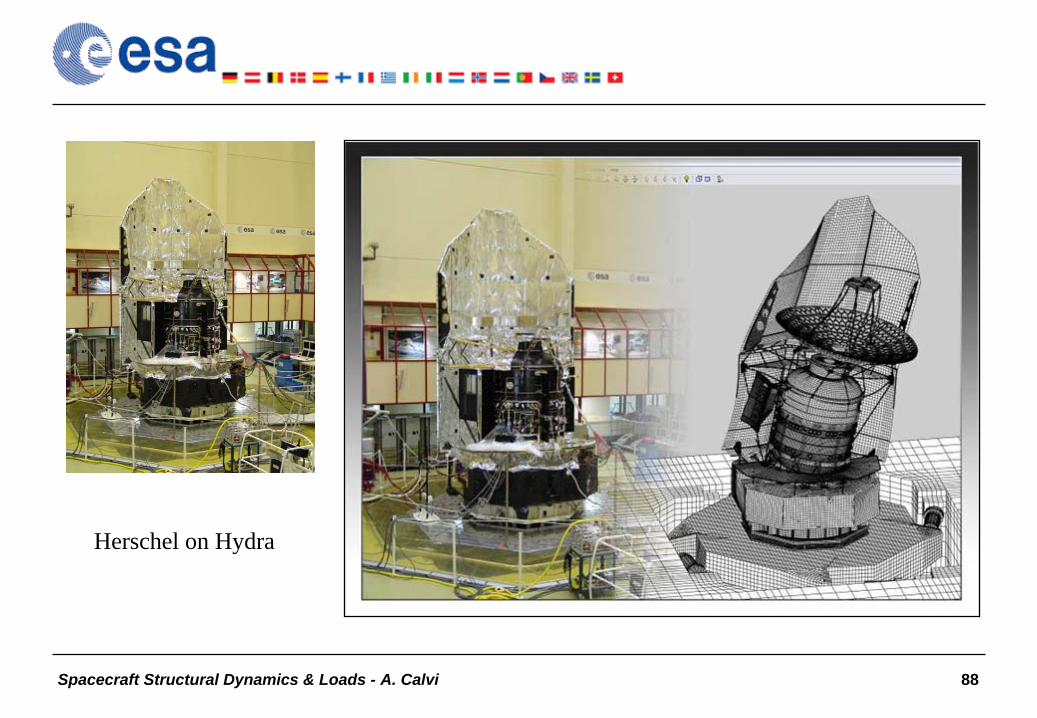
Herschel on Hydra

Spacecraft Structural Dynamics & Loads - A. Calvi 89
Acoustic test (objectives)Acoustic test (objectives)
•
Demonstrate the ability of a specimen to withstand the acoustic environment during launch
•
Validation of analytical models
•
System level tests verify equipment qualification loads
•
Acceptance test for S/C flight models

Spacecraft Structural Dynamics & Loads - A. Calvi 90
Ariane 5 Ariane 5 –– Acoustic noise spectrum under the fairingAcoustic noise spectrum under the fairing

Spacecraft Structural Dynamics & Loads - A. Calvi 91
Acoustic spectra for different launchersAcoustic spectra for different launchers

Spacecraft Structural Dynamics & Loads - A. Calvi 92
Shock test. Objectives and remarksShock test. Objectives and remarks
•
Demonstrate the ability of a specimen to withstand the shock loads during launch and operation
•
Verify equipment qualification loads during system level tests
•
System level shock tests are generally performed with the actual shock generating equipment (e.g. clamp band release)
•
or by using of a sophisticated pyro- shock generating system (SHOGUN for
ARIANE 5 payloads)

Spacecraft Structural Dynamics & Loads - A. Calvi 93
Shock response spectra for different launchers (spacecraft separShock response spectra for different launchers (spacecraft separation)ation)
Note: for a consistentcomparison, datashould refer tothe same adapter.

Spacecraft Structural Dynamics & Loads - A. Calvi 94
Shock machine (metalShock machine (metal--metal pendulum impact machine)metal pendulum impact machine)

Spacecraft Structural Dynamics & Loads - A. Calvi 95
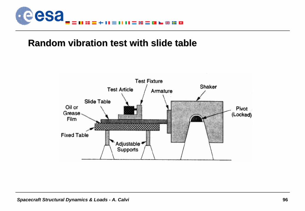
Random Vibration Test (vs. Acoustic Test)Random Vibration Test (vs. Acoustic Test)
Purpose: verify strength and structural life by introducing random vibration through the mechanical interface
•
Random Vibration–
base driven excitation
–
better suited for Subsystem / Equipment tests–
limited for large shaker systems
•
Acoustic–
air pressure excitation
–
better suited for S/C and large Subsystems with low mass / area density
Spacecraft Structural Dynamics & Loads - A. Calvi 96
Random vibration test with slide tableRandom vibration test with slide table

Spacecraft Structural Dynamics & Loads - A. Calvi 97
Random vibration test: dataRandom vibration test: data--processing bandwidthprocessing bandwidth
•
The figures show how the data-processing bandwidth can affect a calculated power spectral density. Whether a PSD satisfies criteria for level and tolerance depends on the frequency bandwidth used to process the measured acceleration time history.
Spacecraft Structural Dynamics & Loads - A. Calvi 98
Spacecraft Structural Dynamics & Loads (2)
•
Payload-launcher Coupled Loads Analysis (CLA)•
Mechanical tests
–
Modal survey test–
Sinusoidal vibration test
–
Acoustic noise test–
Shock test
–
Random vibration test•
Overtesting, “notching”
and sine vibration testing
•
Mathematical model updating and validation•
Summary and conclusive remarks
–
Bibliography

Spacecraft Structural Dynamics & Loads - A. Calvi 99
Overtesting:Overtesting: an introductionan introduction (vibration absorber effect)(vibration absorber effect)

Spacecraft Structural Dynamics & Loads - A. Calvi 100
Introduction to overtesting and notching•
The qualification of the satellite to low frequency transient is normally achieved by a base-shake test
•
The input spectrum specifies the acceleration input that should excite the satellite, for each axis
•
This input is definitively different from the mission loads, which are transient
•
Notching: “Reduction of acceleration input spectrum in narrow frequency bands, usually where test item has resonances”
(NASA-HDBK-7004)
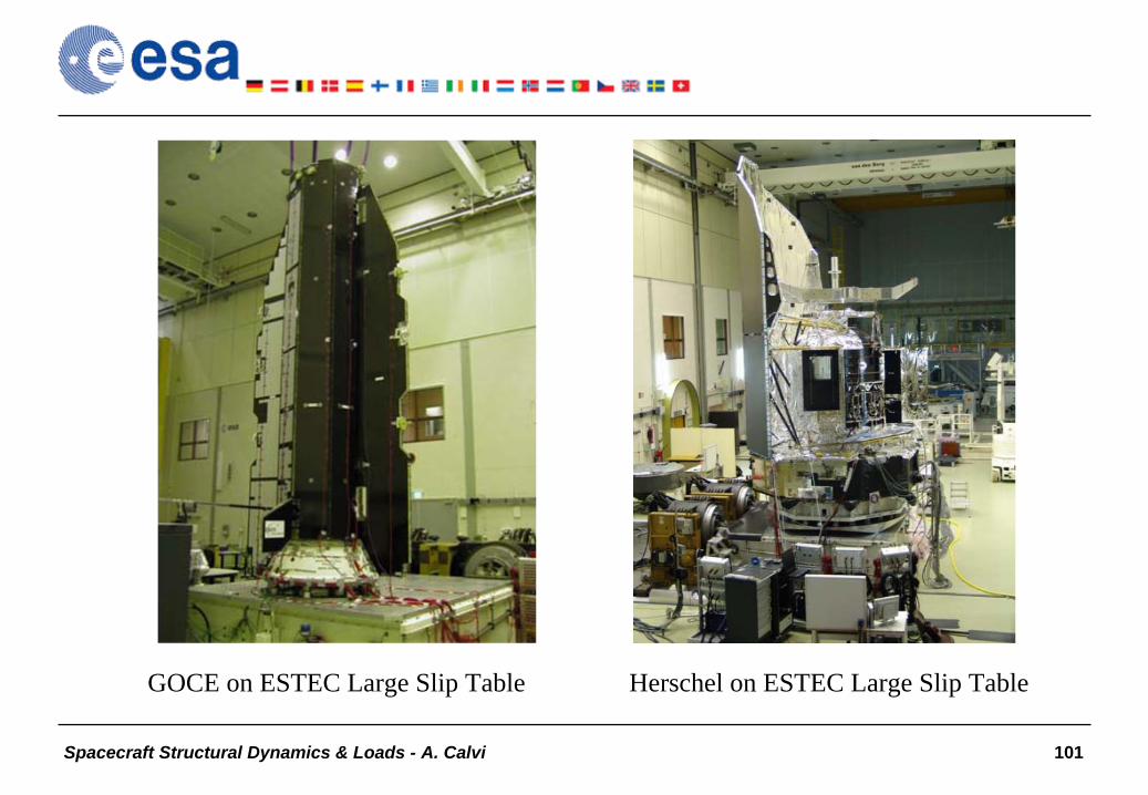
Spacecraft Structural Dynamics & Loads - A. Calvi 101
GOCE on ESTEC Large Slip Table Herschel on ESTEC Large Slip Table

Spacecraft Structural Dynamics & Loads - A. Calvi 102
The overtesting problem (causes)•
Difference in boundary conditions between test and flight configurations
–
during a vibration test, the structure is excited with a specified input acceleration that is the envelope of the flight interface acceleration, despite the amplitude at certain frequencies drops in the flight
configuration (there is a feedback from the launcher to the spacecraft in the main modes of the spacecraft)
•
The excitation during the flight is not a steady-state sine function and neither a sine sweep but a transient excitation with some cycles
in a
few significant resonance frequencies •
The objective of notching of the specified input levels is to take into account the real dynamic response for the different flight events. In practice the notching simulates the antiresonances
in the coupled
configuration

Spacecraft Structural Dynamics & Loads - A. Calvi 103
Shock Response Spectrum and Equivalent Sine Input
•
A shock response spectrum is a plot of maximum “response”
(e.g.
displacement, stress, acceleration) of single degree-of-freedom (SDOF) systems to a given input versus some system parameter, generally the undamped natural frequency.

Spacecraft Structural Dynamics & Loads - A. Calvi 104
SRS/ESI of the following
transient
acceleration:
QSRSESI
ESI
ESI
Spacecraft Structural Dynamics & Loads - A. Calvi 105
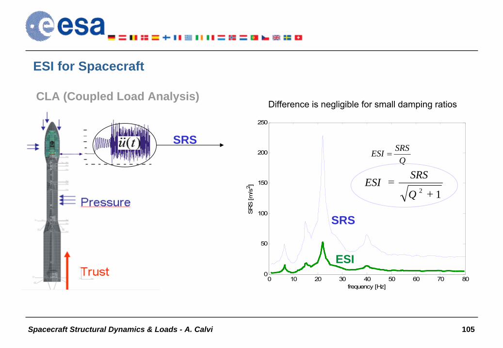
ESI for Spacecraft
CLA (Coupled Load Analysis)
0 10 20 30 40 50 60 70 800
50
100
150
200
250
SR
S [m
/s2 ]
frequency [Hz]
SRSQ
SRSESI
ESI
12
Q
SRSESI
SRS
Difference is negligible for small damping ratios

Spacecraft Structural Dynamics & Loads - A. Calvi 106
/[ sm
][s
2.41
[Hz
]/[ sm 2.46
2DOF2DOF]/[ sm
][s
01.0Hz23frequencynatural
[Hz
Hz23frequencynatural 1.97 01.0
]/[ sm
Transient responseTransient response
Frequency response at ESI levelFrequency response at ESI level
SDOFSDOF

Spacecraft Structural Dynamics & Loads - A. Calvi 107
The effects of the sine sweep rate on the structural response
•
The acceleration enforced by the shaker is a swept frequency function
•
The sweep is amplitude modulated•
Acceleration transient response can be significantly lower that the steady-state frequency response
2 oct/min
0 10 20 30 40 50 60-5
0
5
time [s]
acce
lara
tion
[m/s
2 ] 4 oct/min

Spacecraft Structural Dynamics & Loads - A. Calvi 108
Effect of sweep rate Effect of sweep rate on isolated peak for increasing and decreasing on isolated peak for increasing and decreasing frequency sweepsfrequency sweeps
The sweep rate V
has 3 effects:
•
a variation (sign of V) of the frequency of the peak: Δf
•
A decrease of the peak amplitude: ΔA
•
An increase of the peak width (with loss of symmetry): Δζ
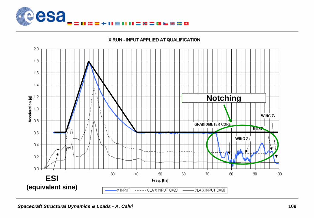
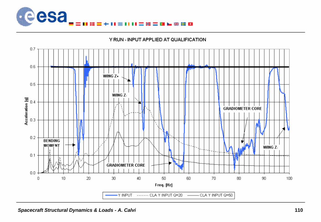
Spacecraft Structural Dynamics & Loads - A. Calvi 109
Notching
ESI (equivalent sine)
Spacecraft Structural Dynamics & Loads - A. Calvi 110

Spacecraft Structural Dynamics & Loads - A. Calvi 111

Spacecraft Structural Dynamics & Loads - A. Calvi 112
SineSine--burst load testburst load test•
The sine-burst test is used to apply a quasi-static load to a test item in order to strength qualify the item and its design for flight
•
A secondary objective is to minimize potential fatigue damage to
the test item
•
For components and subsystems, the fixture used for vibration testing often can also be used for sine-burst strength testing. For this reason, strength qualification and random vibration qualification can often be performed during the same test session which saves time and money
•
Since the test is intended to impart a quasi-static load to the test item, the test frequency “must be”
(in principle) below the fundamental
resonant frequency of the test item•
The sine-burst test is a cost effective alternative to either static loads or to centrifuge testing

Spacecraft Structural Dynamics & Loads - A. Calvi 113
““(Sine) quasi static load test(Sine) quasi static load test”” (sine burst)(sine burst)

Spacecraft Structural Dynamics & Loads - A. Calvi 114
Random vibration test: notching of test specificationRandom vibration test: notching of test specification
Illustration of notching of random vibration test specification,at the frequencies of strong test item resonances

Spacecraft Structural Dynamics & Loads - A. Calvi 115
Spacecraft Structural Dynamics & Loads (2)
•
Payload-launcher Coupled Loads Analysis (CLA)•
Mechanical tests
–
Modal survey test–
Sinusoidal vibration test
–
Acoustic noise test–
Shock test
–
Random vibration test•
Overtesting, “notching”
and sine vibration testing
•
Mathematical model updating and validation•
Summary and conclusive remarks
–
Bibliography

Spacecraft Structural Dynamics & Loads - A. Calvi 116
Validation of Finite Element Models (with emphasis on Structural Dynamics)
“Everyone believes the test data except for the experimentalist, and no one believes the finite element model except for the analyst”
“All models are wrong, but some are still useful”

Spacecraft Structural Dynamics & Loads - A. Calvi 117
Verification and Validation Definitions (ASME Standards Committee: “V & V in Computational Solid Mechanics”)
•
Verification (of codes, calculations): Process of determining that a model implementation accurately represents the developer’s conceptual description of the model and the solution to the model
–
Math issue: “Solving the equations right”
•
Validation: Process of determining the degree to which a model is an accurate representation of the real world from the perspective of the intended uses of the model
–
Physics issue: “Solving the right equations”
Note: objective of the validation is to maximise confidence in the predictive capability of the model
Spacecraft Structural Dynamics & Loads - A. Calvi 118
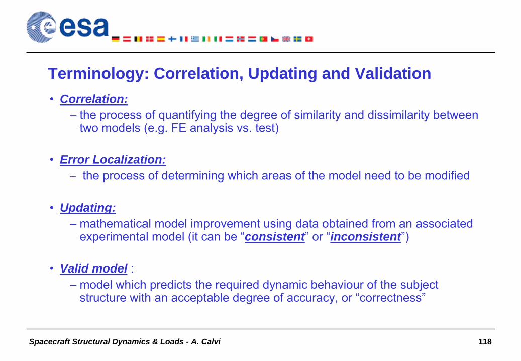
Terminology: Correlation, Updating and Validation•
Correlation:
–
the process of quantifying the degree of similarity and dissimilarity between two models (e.g. FE analysis vs. test)
•
Error Localization:–
the process of determining which areas of the model need to be modified
•
Updating:–
mathematical model improvement using data obtained from an associated experimental model (it can be “consistent” or “inconsistent”)
•
Valid model :–
model which predicts the required dynamic behaviour of the subject structure with an acceptable degree of accuracy, or “correctness”

Spacecraft Structural Dynamics & Loads - A. Calvi 119
Some remarks on the validation of “critical analyses”
•
Loads analysis is probably the single most influential task in designing a space structure
•
Loads analysis is doubly important because it is the basis for static test loads as well as the basis for identifying the target responses and “notching criteria”
in sine tests
•
A single mistake in the loads analysis can mean that we design and test the structure to the wrong loads
•
We must be very confident in our loads analysis, which means we must check the sensitivity of our assumptions and validate the loads analysis that will be the basis of strength analysis and static testing
•
Note: Vibro-acoustic, random and shock analyses are usually “not critical”
in the sense that we normally use environmental tests to
verify mechanical requirements

Spacecraft Structural Dynamics & Loads - A. Calvi 120
ASME V&V GuideASME V&V Guide vs. vs. Validation of FEM for CLAValidation of FEM for CLA
•
Reality of interest: satellite / low frequency transient environment•
Intended use of the model: launcher/satellite CLA (to predict system behaviour for cases that will not be tested)
•
Response features of interest: “CLA loads” (forces, accelerations, etc.)•
Validation testing: modal survey test or base-drive sine test
•
Experimental data: accelerations (and forces) (time histories)•
Experimental features of interest: natural frequencies, mode shapes…
•
Metrics: relative errors (e.g. natural frequencies), MAC, etc.•
Accuracy requirements: e.g. ECSS-E-ST-32-11
•
Computational model: NASTRAN F.E. model (eigenmodes analysis)•
Validation documentation: ECSS-E-ST-32 (DRD Test/analysis correlation)

Spacecraft Structural Dynamics & Loads - A. Calvi 121
Targets of the correlation (features of interest for quantitative comparison)
Characteristics that most affect the structure response to applied forces
•
Natural frequencies•
Mode shapes
•
Modal effective masses•
Modal damping
•
…•
Total mass, mass distribution
•
Centre of Gravity, inertia•
Static stiffness
•
Interface forces•
…

Spacecraft Structural Dynamics & Loads - A. Calvi 122
Correlation of mode shapesCorrelation of mode shapes
•
Spacehab FEM coupled to the test rig model & Silhouette

Spacecraft Structural Dynamics & Loads - A. Calvi 123
GOCE modal analysis and survey testGOCE modal analysis and survey test

Spacecraft Structural Dynamics & Loads - A. Calvi 124
CrossCross--Orthogonality Check (COC) and Modal Assurance Criterion (MAC) Orthogonality Check (COC) and Modal Assurance Criterion (MAC)
•
The cross-orthogonality
between the analysis and test mode shapes with respect to the mass matrix is given by:
•
The MAC between a measured mode and an analytical mode is defined as:
aTm MC
as
Tasmr
Tmr
asTmr
rsMAC
2
Note: COC and MAC do not give a “useful” measure of the error!

Spacecraft Structural Dynamics & Loads - A. Calvi 125
Columbus: Cross-Orthogonality Check up to 35 Hz (target modes) TEST
1 2 3 4 5 6 7 8 9 10 11 12 13 14 15 16 17 18 19 20
FEM Err.% [Hz] 13.78 15.80 17.20 23.81 24.23 24.65 25.36 25.59 26.59 27.19 27.53 28.87 30.19 30.55 32.73 33.15 33.86 34.57 35.21 36.16
1 -2.94 13.37 1.00
2 -0.95 15.65 1.00
3 -1.73 16.90 0.99
4 -3.26 23.03 0.93 0.35
5 -1.16 23.95 0.34 0.93
6 -2.00 24.16 0.95
7 -1.98 24.86 0.95 0.27
8 -0.12 25.56 0.86
9 -0.95 26.34 0.22 0.90
10 -2.65 26.47 0.95
11 -0.40 27.42 0.26 0.96
12 -3.65 27.82 0.82 0.27
13 -6.00 28.38 0.46 0.89
15 1.19 30.91 0.26 0.95
17 1.63 33.26 0.94 0.21 0.32
18 - 33.71 0.64 0.34 0.62
19 -4.72 34.45 0.95
20 1.21 34.99 0.57 0.81

Spacecraft Structural Dynamics & Loads - A. Calvi 126
MPLM Modal CorrelationMPLM Modal Correlation
Spacecraft Structural Dynamics & Loads - A. Calvi 127
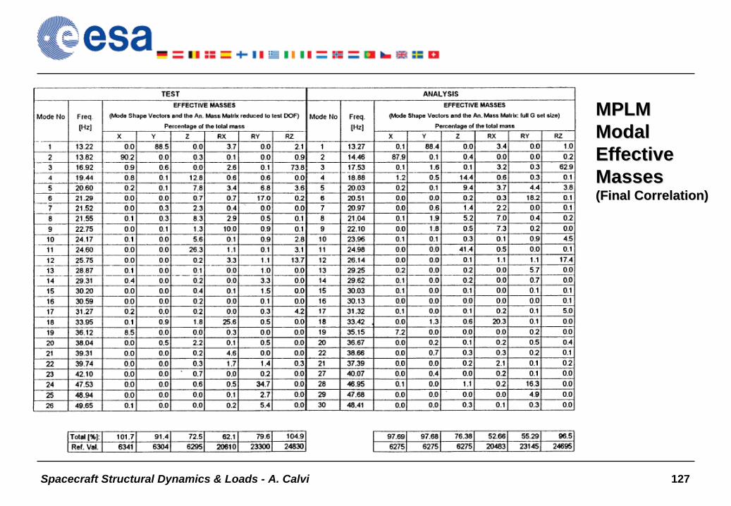
MPLMMPLM ModalModal EffectiveEffective MassesMasses (Final Correlation)(Final Correlation)

Spacecraft Structural Dynamics & Loads - A. Calvi 128
Soho SVM – Cross-Orthogonality CheckF.E.M.
1 2 3 4 8 9 10 15 21 26 29 30 31TEST Err. % Freq. Hz 34.83 37.24 44.07 45.19 51.51 52.68 55.46 62.18 70.92 77.99 81.53 82.25 84.42
1 2.87 35.86 0.87 0.462 0.00 37.24 0.47 0.873 4.17 45.99 0.874 4.78 47.46 0.77 0.245 -3.39 49.82 -0.33 0.766 0.96 53.19 0.75 0.227 2.10 56.65 0.79 0.218 58.67 -0.28 -0.35 -0.229 60.24 -0.30 -0.22 0.46 0.4610 3.30 64.30 0.6111 66.40 0.21 0.3212 67.50 0.45 -0.4313 68.73 -0.3814 69.6815 71.6916 72.71 0.37 -0.3317 3.30 73.34 0.21 0.8518 74.7819 75.6320 78.77 -0.2421 82.1222 7.72 84.51 0.7623 5.54 86.31 0.87 -0.2324 7.21 88.64 0.6425 5.45 89.29 -0.33 0.6326 94.4427 97.1528 99.56
Spacecraft Structural Dynamics & Loads - A. Calvi 129
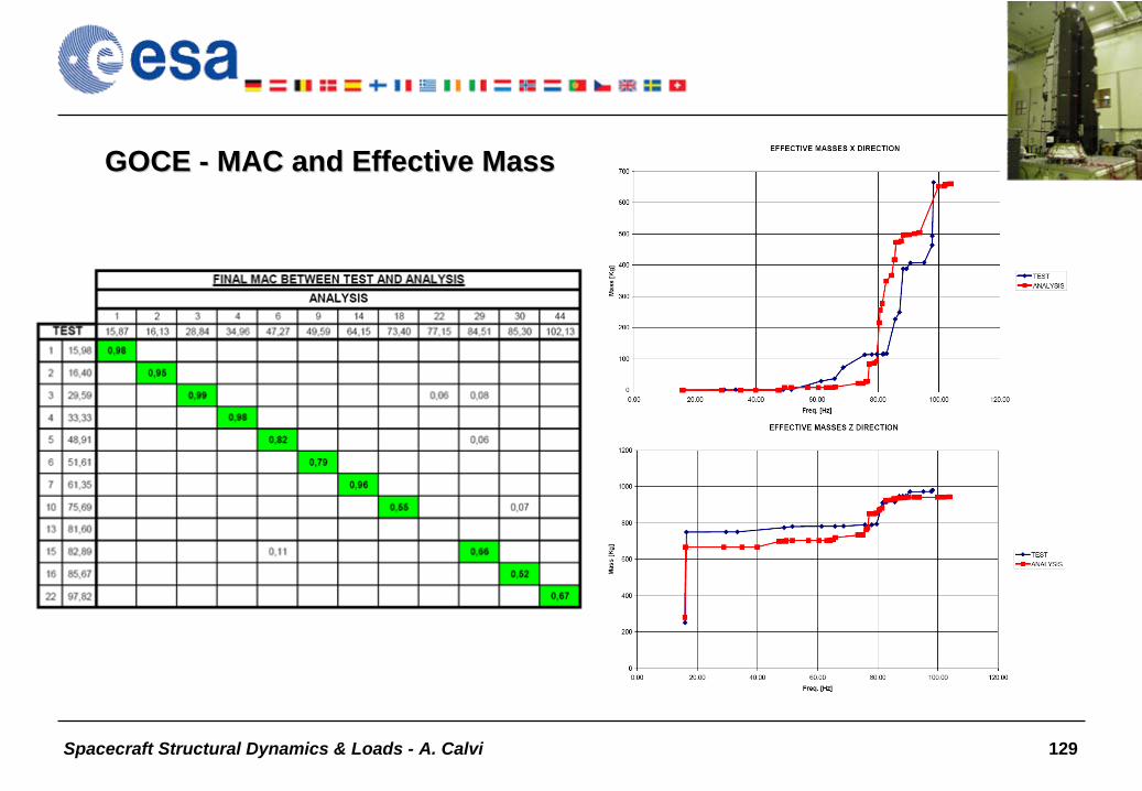
GOCE GOCE -- MAC and Effective MassMAC and Effective Mass

Spacecraft Structural Dynamics & Loads - A. Calvi 130
Aeolus STM: comparison of transfer functionsAeolus STM: comparison of transfer functions
Sine test response, FEM predicted response and post-test (updated FEM) response

Spacecraft Structural Dynamics & Loads - A. Calvi 131
Lack of Matching between F.E. Model and Test•
Modelling uncertainties and errors (model is not completely physically representative)
–
Approximation of boundary conditions–
Inadequate modelling of joints and couplings–
Lack or inappropriate damping
representation–
The linear assumption of the model versus test non-linearities–
Mistakes
(input errors, oversights, etc.)
•
Scatter in manufacturing–
Uncertainties in physical properties
(geometry, tolerances, material properties)
•
Uncertainties and errors in testing–
Measured data
or parameters contain levels of errors–
Uncertainties in the test set-up, input loads, boundary conditions
etc.–
Mistakes
(oversights, cabling errors, etc.)

Spacecraft Structural Dynamics & Loads - A. Calvi 132
Test-Analysis Correlation Criteria The degree of similarity or dissimilarity establishing that the correlation between measured and predicted values is acceptable
ECSS-E-ST-32-11 Proposed Test / Analysis Correlation Criteria

Spacecraft Structural Dynamics & Loads - A. Calvi 133
Model Updating Using Design Sensitivity and Optimisation (traditional basic assumptions)
•
Some appropriate objective functions, within design optimisation codes, can be used to drive a F.E.M. to behave in the same manner as the real structure portrayed by a set of numerical test results
•
The test results accurately depict the true behaviour of the structure

Spacecraft Structural Dynamics & Loads - A. Calvi 134
Find the set of design variables X that
•
Minimise
•
Subject to bounds on the design variables X
where and are the test and analysis eigenvalues, P
is the number of paired modes, and are weighting factors
2
1
P
j mj
mjajjg wwE X
Example of Optimisation
uii
li xxx
m a
jw gw

Spacecraft Structural Dynamics & Loads - A. Calvi 135
Model updating: example of “objective functions”Natural Frequency:
eea
f fffd
Mode Shape:
eead
(: modal scale factor)
Effective Transmissibilities: e
eaT~ T~
T~T~d
Effective Masses: e
eaM~ M~
M~M~d
Objective Function
bWbF T with
M~T~
f
dddd
b and
M~T~
f
ww
ww
W

Spacecraft Structural Dynamics & Loads - A. Calvi 136
Location of Modelling Errors and Selection of the Design Variables Based on Sensitivity Analysis
Criterion (selection of design variables):The design variables should be selected for those elements or element groups which have an influence on the eigenfrequencies
and mode shapes which are targeted during the correlation/updating process (in addition to analyst’s knowledge of uncertain modelled regions of the structure and/or results of
other error
localisation analyses)
Two basic approaches are possible:•
Initial model sensitivities (e.g. initial derivative approach)•
“A Posteriori”
Approach (at the end of a preliminary optimisation process)
Criterion (error localisation):To determine how effective certain physical properties changes might be in reducing the difference between measured and calculated data (however high sensitivity is not generally a sufficient reason for the selection of a candidate parameter!)

Spacecraft Structural Dynamics & Loads - A. Calvi 137
Limitations of the “sensitivity and optimisation” approach•
Largest changes can be in the most sensitive parameters rather than those in error (→
inconsistent updating and misleading error
localization)
•
Errors of insensitive regions cannot be detected
•
The success of the updating procedure can strongly depend on the selection of the design parameters to be updated (it could be
necessary to consider several sets of design parameters to detect erroneous regions of the structure)
•
The approach could be “short-sighted”
(possible convergence to local minima)

Spacecraft Structural Dynamics & Loads - A. Calvi 138
ExerciseExercise•
Calculate natural frequencies and mode shapes of the 2-DOF satellite represented in the figure
•
Consider a perturbed model, representing the real (tested) structure, having
–
k1
= 60 E5 N/m–
k2
= 130 E5 N/m•
Calculate natural frequencies and mode shapes for the perturbed (test) model
•
Correlate the 2 models, i.e. calculate:–
Natural frequency deviations
–
Mode shapes cross-orthogonality
check

Spacecraft Structural Dynamics & Loads - A. Calvi 139
Solutions of the exerciseSolutions of the exercise

Spacecraft Structural Dynamics & Loads - A. Calvi 140
ExerciseExercise…… part 2part 2

Spacecraft Structural Dynamics & Loads - A. Calvi 141
Summary and Conclusive Remarks
•
The role of structural dynamics in a space project•
Dynamic analysis types
•
The effective mass concept•
Design load cycles & verification loads cycle
•
Payload-launcher Coupled Loads Analysis•
Mechanical tests
•
Overtesting
& “notching”•
Mathematical model updating and validation

Spacecraft Structural Dynamics & Loads - A. Calvi 142
BibliographyBibliography•
Sarafin T.P. Spacecraft Structures and Mechanisms, Kluwer, 1995
•
Craig R.R., Structural Dynamics –
An introduction to computer methods, J. Wiley and Sons, 1981
•
Clough R.W., Penzien
J., Dynamics of Structures, McGraw-Hill, 1993•
Ewins
D.J., Modal Testing –
Theory, practice and applications, Research Studies
Press, Second Edition, 2000•
Wijker
J., Mechanical Vibrations in Spacecraft Design, Springer, 2004
•
Girard A., Roy N., Structural Dynamics in Industry, J. Wiley and
Sons, 2008•
Steinberg D.S., Vibration Analysis for Electronic Equipment, J. Wiley and Sons, 2000
•
Friswell
M.I., Mottershead
J.E., Finite Element Model Updating in Structural Dynamics, Kluwer
1995
•
Ariane
5 User’s Manual, Arianespace, http://www.arianespace.com/

Spacecraft Structural Dynamics & Loads - A. Calvi 143
Bibliography Bibliography -- ECSS DocumentsECSS Documents
•
ECSS-E-ST-32 Space Project Engineering - Structural•
ECSS-E-ST-32-03 Structural finite element models
•
ECSS-E-ST-32-10 Structural factors of safety for spaceflight hardware
•
ECSS-E-ST-32-02 Structural design and verification of pressurized hardware
•
ECSS-E-ST-32-11 Modal survey assessment•
ECSS-E-ST-32-01 Fracture control
•
ECSS-E-10-02 Space Engineering - Verification•
ECSS-E-10-03 Space Engineering - Testing

Spacecraft Structural Dynamics & Loads - A. Calvi 144
THE END!Acknowledgements:
ALENIA SPAZIO, Italy, for the data concerning the projects GOCE, COLUMBUS, MPLM and SOHO
EADS ASTRIUM, UK, for the data concerning the project AEOLUS and EarthCARE
ESA/ESTEC, Structures Section, NL, for the data concerning ARIANE 5 FE model and LV/SC CLA