Embed Size (px)
Citation preview
Technical Notes
Post-Tensioning Expertise and Design March 12, 2019
TN500_floors_1
STRUCTURAL DESIGN OF COLUMN-SUPPORTED CONCRETE FLOORS
First draft, under review; March 12, 2019
Bijan Aalami1
This Technical Note explains the three primary methods for the safe design of column-supported concrete floors, including those reinforced with post-tensioned tendons. List of contents 1 – DESGIN OBJECTIVE 2 – DESIGN FOR COLLAPSE PREVENTION
2.1 Ductility and Collapse A-Glass plate B- Concrete slab
3 – SINGLE LOAD PATH FOR SERVICEABIITY; MULTIPLE LOAD PATH FOR SAFETY 3.1 Load Path
4 – COLLAPSE CONFIGURATION – ULS CONDITION 4.1 Design-Built Ductility 4.2 Collapse Configuration
5 – FLOOR SLAB MODELING FOR STRENGTH 5.1 Structural Modeling Options
5.1.1 Elastic solution load Path 5.1.2 Strip method load Path 5.1.3 Yield line method
5.2 Failure Mechanism of Regular Column-Supported Floors 5.3 Design Idealization of Irregular Floors
5.3.1 Strip method option 5.3.2 Elastic solution option 5.3.3 Yield line method of design
5 – EXTRATION OF DESIGN ACTIONS 5.1 Strip Method Design Values 6.2 Elastic Method Design Values
1 Professor Emeritus, San Francisco State University; Principal, ADAPT Corporation; [email protected]
Technical Notes
TN290 - 2
7 – TREATMENT OF TWISTING MOMENTS 7.1 Twisting Moment 7.2 Design for Twisting moment
7.2.1 Distribution of twisting moment in floor slabs 7.2.2 Design for twisting moment/torsion
8 – SUMMARY 1 – DESIGN OBJECTIVE The primary design objective is to conclude with a floor that is (I) serviceable; and (ii) safe for the specified load. The serviceability depends on the intended application. The list of its requirements is not universal. In the common case it is broken down to primary and secondary groups. The primary serviceability checks listed in the major building codes are limits on:
Deflection Cracking Fire protection
The adherence to the preceding requirements varies. For example, limits on deflection and cracking depend strictly on the application. It is the consequence of deflection that governs its permissible value, as opposed to an absolute deflection to span ratio. There is latitude in application of the building code recommended values. Building codes recommend limits for the common residential and commercial structures. The following can be viewed as secondary consideration for serviceability. Again, the importance of each depends on the application
Economy Maintenance Vibration
Design for safety on the other hand is paramount. It applies to all cases. The design outcome should be strong enough to sustain the load it is intended to carry. 2 – DESIGN FOR COLLAPSE PREVENTION A safe design will not lead to collapse of the floor, when subjected to the load it is specified to carry. The building codes require a minimum factor of safety for collapse. The factor of safety is generally expressed as a “load factor.” Depending on the perceived reliability of the design load, the factor can be as high as 1.7. The design shall withstand the “factored” load prior to collapse. Before detailing the design options to prevent collapse, it is important to review the cause and manner of collapse of concrete floors. This is explained next.
Technical Notes
TN290 - 3
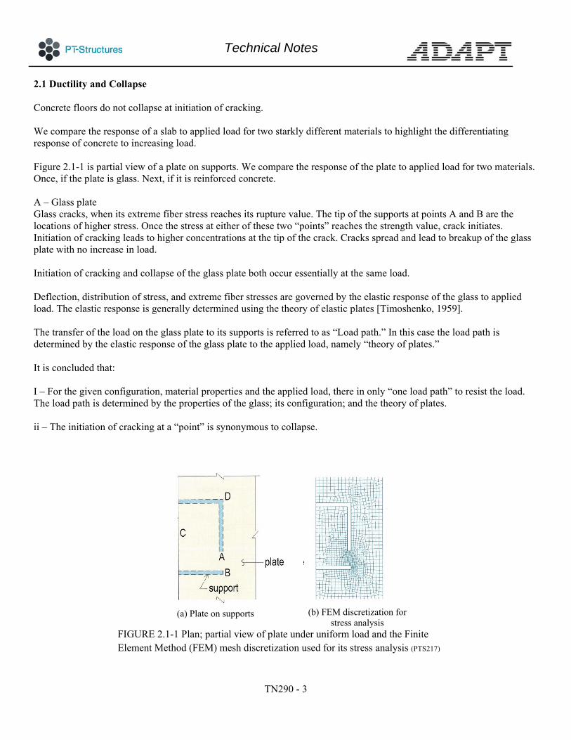
2.1 Ductility and Collapse Concrete floors do not collapse at initiation of cracking. We compare the response of a slab to applied load for two starkly different materials to highlight the differentiating response of concrete to increasing load. Figure 2.1-1 is partial view of a plate on supports. We compare the response of the plate to applied load for two materials. Once, if the plate is glass. Next, if it is reinforced concrete. A – Glass plate Glass cracks, when its extreme fiber stress reaches its rupture value. The tip of the supports at points A and B are the locations of higher stress. Once the stress at either of these two “points” reaches the strength value, crack initiates. Initiation of cracking leads to higher concentrations at the tip of the crack. Cracks spread and lead to breakup of the glass plate with no increase in load. Initiation of cracking and collapse of the glass plate both occur essentially at the same load. Deflection, distribution of stress, and extreme fiber stresses are governed by the elastic response of the glass to applied load. The elastic response is generally determined using the theory of elastic plates [Timoshenko, 1959]. The transfer of the load on the glass plate to its supports is referred to as “Load path.” In this case the load path is determined by the elastic response of the glass plate to the applied load, namely “theory of plates.” It is concluded that: I – For the given configuration, material properties and the applied load, there in only “one load path” to resist the load. The load path is determined by the properties of the glass; its configuration; and the theory of plates. ii – The initiation of cracking at a “point” is synonymous to collapse.
(a) Plate on supports
(b) FEM discretization for
stress analysis FIGURE 2.1-1 Plan; partial view of plate under uniform load and the Finite Element Method (FEM) mesh discretization used for its stress analysis (PTS217)

Technical Notes
TN290 - 4
B – Concrete slab Consider the concrete balcony shown in Fig. 2.1.B-1. It has the same support configuration as the glass panel of Fig. 2.1-1. Under uniform load, the slab will deflect following the plate theory in the same manner as the sheet of glass. It will develop high tensile stresses at the same locations as the glass panel, namely the tips of the walls. The slab will crack at these locations. The cracking at the tips of the walls does not herald slab’s collapse – nor its lack of adequacy to satisfactorily carrying it design load. Cracking leads to the modification of the floor’s initial load path – based on elastic plate theory – to where there is reinforcement and stiffness to resist the load. With increase in load, the initial load path governed by the elastic theory of plates will be continuously re-configured to meet the force demand. At each load increment, the slab draws upon reserve of strength not fully mobilized. This continues, until the strength reserve is exhausted. The continuous modification of load path, with increasing load is the characteristic of concrete slabs. It deviates from the theory of elastic plates. It also deviates from the solution features applicable to the slab’s service condition – in particular deflection and crack initiation. Theory of elastic plates does not apply to the safety evaluation of reinforced concrete floors.
FIGURE 2.1.B-1 Plan; concrete slab with two options for
arrangement of reinforcement (PTS 569) Two of the several options commonly used for reinforcing the balcony is shown in Fig. 2.1.B-1. In one case, the resistance is envisaged by the designer to be provided by a “strip” spanning between the walls A and B. Reinforcement is at the bottom. In the second case, the designer has considered the slab to cantilever over wall C. The reinforcement is at the top. The arrangement of reinforcement is widely different. Both options provide safe slabs. Neither follows elastic theory of plates.

Technical Notes
TN290 - 5
In both options, the resistance is provided by reinforcement in “one direction” only. It is not necessary for a safe design in all cases to provide primary reinforcement in both directions. The necessity of reinforcement in both directions depends on the adequacy of the load path selected by the designer. It is not a design requirement. It is noteworthy that in the early application of the finite element method to automated design of floor slabs, the practice was to consider the elastic response of the floor slab to be its load path for the floor safety. The steps are explained next. (I) the slab is provided with a bottom mesh reinforcement of known cross-sectional area per unit length. (ii) The moment contour obtained from the FEM elastic solution is used to calculate the contour of required reinforcement. This provides the intensity of the required reinforcement in each direction (Fig. 2.1.B-2) (iii) The moment contour is matched against the designer-provided mesh. The shortfall of reinforcement is provided with individual bars.
(a) Reinforcement along x-x (b) Reinforcement along y-y
FIGURE 2.1.B-2 Plan; Distribution contour of reinforcement along X-X and Y-Y directions.
The distribution of reinforcement follows the elastic response of the slab to the applied load.
The preceding is a valid design method, but not applicable to design of post-tensioned floor systems. As shown in Fig. 2.1.B-3, in practice, the reinforcement for the entire tributary of a column line and its tributary is positioned over a narrow band along the line of columns. The reinforcement is not distributed throughout the floor, as required by the preceding method – namely plate theory.
Technical Notes
TN290 - 6
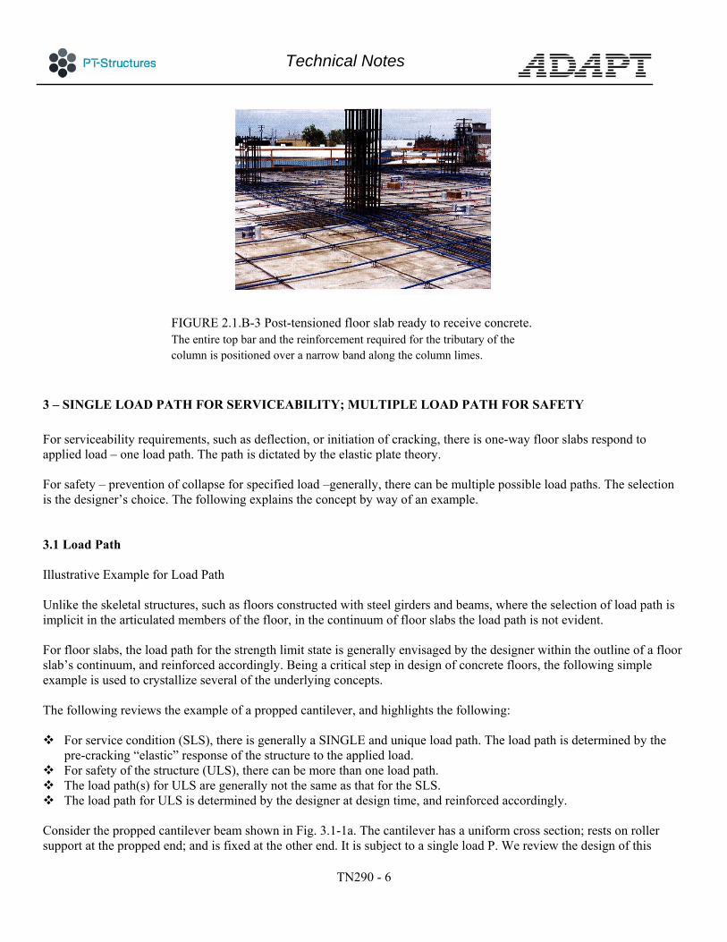
FIGURE 2.1.B-3 Post-tensioned floor slab ready to receive concrete. The entire top bar and the reinforcement required for the tributary of the column is positioned over a narrow band along the column limes.
3 – SINGLE LOAD PATH FOR SERVICEABILITY; MULTIPLE LOAD PATH FOR SAFETY For serviceability requirements, such as deflection, or initiation of cracking, there is one-way floor slabs respond to applied load – one load path. The path is dictated by the elastic plate theory. For safety – prevention of collapse for specified load –generally, there can be multiple possible load paths. The selection is the designer’s choice. The following explains the concept by way of an example. 3.1 Load Path Illustrative Example for Load Path Unlike the skeletal structures, such as floors constructed with steel girders and beams, where the selection of load path is implicit in the articulated members of the floor, in the continuum of floor slabs the load path is not evident. For floor slabs, the load path for the strength limit state is generally envisaged by the designer within the outline of a floor slab’s continuum, and reinforced accordingly. Being a critical step in design of concrete floors, the following simple example is used to crystallize several of the underlying concepts. The following reviews the example of a propped cantilever, and highlights the following: For service condition (SLS), there is generally a SINGLE and unique load path. The load path is determined by the
pre-cracking “elastic” response of the structure to the applied load. For safety of the structure (ULS), there can be more than one load path. The load path(s) for ULS are generally not the same as that for the SLS. The load path for ULS is determined by the designer at design time, and reinforced accordingly. Consider the propped cantilever beam shown in Fig. 3.1-1a. The cantilever has a uniform cross section; rests on roller support at the propped end; and is fixed at the other end. It is subject to a single load P. We review the design of this

Technical Notes
TN290 - 7
cantilever, on the assumption that the effect of selfweight is negligible compared to the applied load P. This does not change the process of design, nor the conclusions arrived at. Part (b) of the figure shows the free body diagram of the cantilever. The distribution of moment, based on linear elastic material properties, is shown in part (c) of the figure. The deflection of the cantilever, as well as the distribution of stress in the member and the initiation of first crack are associated with this bending moment. In service, the cracks if any are assumed not to be extensive. The elastic response of the structure under the applied load is calculated using the gross cross-sectional dimensions of concrete and its material properties. While it is recognized that the presence of reinforcement has an influence on the deflection and crack formation of the member, due to its small impact in most cases, the presence of reinforcement is generally not accounted for in the SLS design. Deflection of a member and crack formation under service load are part of the serviceability check (SLS). There is only one elastic solution for the applied load shown – hence one load path. The distribution of moment shown in part (c) of the figure, defines the load path for SLS. Let the reinforcement provided in this propped cantilever be two identical layers, one at the top and one at the bottom, each extending over the entire length of the member. For a rectangular section, the provided reinforcement results in a constant resistance capacity for both the positive and the negative moments over the entire length of the member. Increase in the applied load P, beyond the elastic limit of the member, results at first in the post-elastic response of the connection at the fixed support, where the demand moment is most. Upon further increase in load, the rise in the moment demand will be shifted from the support to the rest of the beam, until the resistance of the section below the load P reaches its limit. For the reinforcement distribution assumed, where the positive and negative moment capacities are equal, the strength limit of the member will be reached for a distribution of moment given in part (d-ii) of the figure. The moments shown in part (d-ii) are in static equilibrium with the applied load P. The distribution of moment reflects the load path at ULS for the distribution of reinforcement assumed. At ULS, the distribution of moment is based on the formation of adequate number of plastic hinges that lead to collapse of the member. Observe that the distribution of moment at (ULS) is different from the elastic response in part (c) of the figure. In other words, at ULS the load is carried by a different load path that is governed by the distribution of moment and hinge formation shown in part (d). The observed load path is based on the resistance provided in the member– namely the “assigned” distribution of reinforcement. Alternatively, if the reinforcement provided is only at the bottom. The structure can still be safe, provided the bottom reinforcement can resist the distribution of moment associated with a single hinge below the load, In summary, for the propped cantilever, we conclude that there is a single load path for its in-service response, and several load path options for its safety. Each load path at the ULS is function of the distribution, and amount of the provided reinforcement.

Technical Notes
TN290 - 8
FIGURE 3.1 -1 Propped cantilever under a single load.
Elastic response and an alternative failure mode option based
Further, the premise for a valid load path at ULS is that (I) the distribution of forces, at ULS shall be in equilibrium with the applied load, (ii) at each point along the assumed load path, the member shall be provided with resistance adequate to meet the distribution of actions assigned to it on the load path; and finally (iii) the member shall have adequate ductility to undergo post-elastic deformation and re-distribute the actions to the selected load path. Figure 3.1-2 illustrates two other load path options for ULS of the same example. In both options, the distribution of moment is in equilibrium with the applied load P. The objective of this second figure is to re-emphasize the multi load path possibilities of design at ULS.

Technical Notes
TN290 - 9
FIGURE 3.1-2 Examples of load path options for safe design of
propped cantilever under a concentrated load
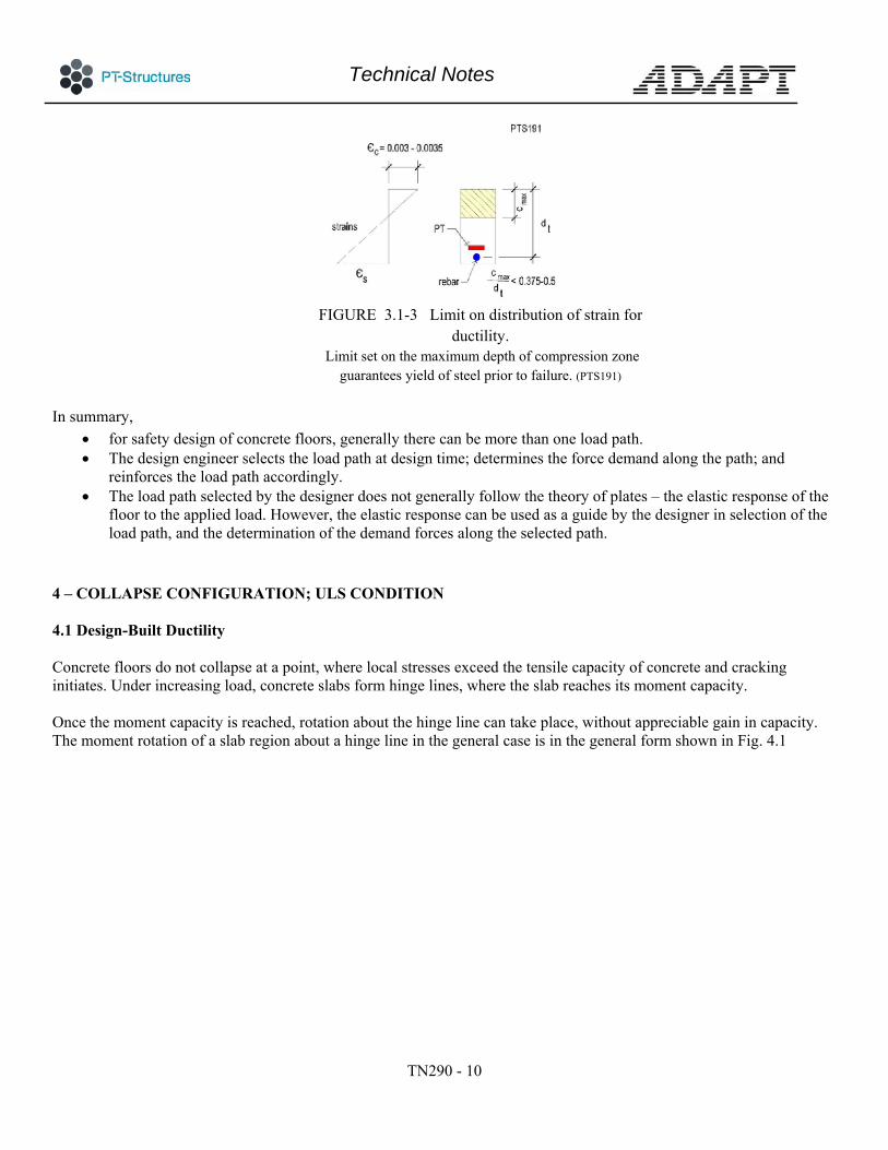
Part (a) of the figure is the re-statement of conditions for a safe design. In one option (part b), we designate a moment capacity of 0.1PL at the support. From equilibrium of the system, the capacity assignment leads to the moment diagram shown in part (b-ii). Reinforcing the structure according to this moment diagram, will lead to a safe design. In the second alternative, assign a moment capacity of 0.2PL to the support. This assumption results in the moment distribution shown in part (c-ii). When reinforced accordingly, the structure will be again safe. It is reiterated that for the safety of the structure (ULS) there can be more than one load path. Each path follows the designer assumption of capacity assignment (provision of reinforcement). The central point is that, at ULS the objective is not to replicate the “elastic response” of the structure. Rather, the objective is to provide a safe load path that often will be different from the elastic (initial) response of the structure. The ability of a concrete section to undergo limited rotation past its elastic limit, while maintaining its elastic capacity is measure of its ductility - an essential characteristic in floor system design. Major building codes have provisions that guarantee the necessary ductility for member design. Ductility of a concrete section is achieved by forcing failure to initiate by yielding of reinforcement, as opposed to crushing of concrete. For sections in primarily bending, this is done by limiting the depth of the neutral axis, as illustrated in Fig. 3.1-3. The ratio of c/dt is controlled to initiate the failure by yielding in tension reinforcement
Technical Notes
TN290 - 10
FIGURE 3.1-3 Limit on distribution of strain for
ductility. Limit set on the maximum depth of compression zone
guarantees yield of steel prior to failure. (PTS191)
In summary,
for safety design of concrete floors, generally there can be more than one load path. The design engineer selects the load path at design time; determines the force demand along the path; and
reinforces the load path accordingly. The load path selected by the designer does not generally follow the theory of plates – the elastic response of the
floor to the applied load. However, the elastic response can be used as a guide by the designer in selection of the load path, and the determination of the demand forces along the selected path.
4 – COLLAPSE CONFIGURATION; ULS CONDITION 4.1 Design-Built Ductility Concrete floors do not collapse at a point, where local stresses exceed the tensile capacity of concrete and cracking initiates. Under increasing load, concrete slabs form hinge lines, where the slab reaches its moment capacity. Once the moment capacity is reached, rotation about the hinge line can take place, without appreciable gain in capacity. The moment rotation of a slab region about a hinge line in the general case is in the general form shown in Fig. 4.1
Technical Notes
TN290 - 11
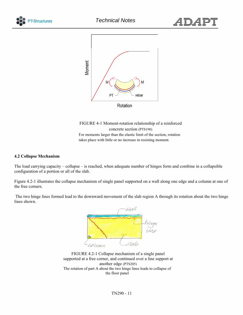
FIGURE 4-1 Moment-rotation relationship of a reinforced concrete section (PTS190)
For moments larger than the elastic limit of the section, rotation takes place with little or no increase in resisting moment.
4.2 Collapse Mechanism The load carrying capacity – collapse – is reached, when adequate number of hinges form and combine in a collapsible configuration of a portion or all of the slab. Figure 4.2-1 illustrates the collapse mechanism of single panel supported on a wall along one edge and a column at one of the free corners. The two hinge lines formed lead to the downward movement of the slab region A through its rotation about the two hinge lines shown.
FIGURE 4.2-1 Collapse mechanism of a single panel
supported at a free corner, and continued over a line support at another edge (PTS205)
The rotation of part A about the two hinge lines leads to collapse of the floor panel

Technical Notes
TN290 - 12
At collapse, the work done by the external load causing the collapse is resisted by the slab’s internal work of the moments at hinge lines. The equivalency of the two governs the failure mode. At collapse, the distribution of reinforcement across a hinge is not critical. It is the amount of reinforcement and location with respect to the depth of the hinge section that determine its contribution, not the location along the length of the hinge line. Generally, there can be more than one collapse mechanism for a given floor system. The governing mechanism for design is the one which takes place at the smallest of load leading to a collapse mechanism. The arrangement of reinforcement; the geometry of the floor and its support; and the configuration of the applied load determine the collapse mechanism. 5 – FLOOR SLAB MODELING FOR STRENGTH 5.1 Structural Modeling Options There are different options for strength design of floor slabs. The common procedure is the strip method. Other options, such as the strict application of plate theory and yield line procedure are also used. The focus of what follows is the strip method. Other options are briefly addressed for completeness. Consider the design of the single floor panel shown in Fig. 5-1. The panel is under a centrally applied concentrated load.
FIGURE 5-1 Panel under concentrated load P at center
Three methods are reviewed. (Fig. 5.2) The methods are: Elastic plate theory Strip method Yield line method

Technical Notes
TN290 - 13
(a) Elastic solution method; reinforcement
distributed throughout the slab based on the distribution of moments shown
(b) Yield line method; reinforcement is primarily
placed at bottom normal to the hinge lines
(c) Design strip method: Design strip along the diagonal is selected as load path and reinforced
to resist the entire force
(d) Design strip method; Intersecting design strips. Each strip is reinforced for the designer-assigned
fraction of load to resist
FIGURE 5-2 Options for strength design of floor slabs 5.1.1 Elastic solution load path Using the theory of plates, the distribution of moments throughout the panel is determined. At each point on the panel, reinforcement is provided to resist the computed moment demand at that point. The distribution of reinforcement follows strictly the solution of the panel based on the theory of elastic plates (Fig. 5-2a) 5.1.2 Strip method load path In the strip method, slab bands within the body of the floor slab are envisaged as load path paths (strips) for transfer of applied load to the supports. The forces generated along each of the assumed strips are determined and provided with adequate reinforcement. Figure 5.2c and 5.2d illustrate two applications of the strip method in its simple form. 5.1-3 Yield line method
Technical Notes
TN290 - 14
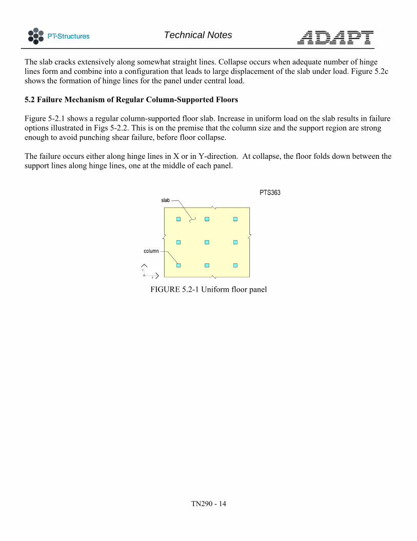
The slab cracks extensively along somewhat straight lines. Collapse occurs when adequate number of hinge lines form and combine into a configuration that leads to large displacement of the slab under load. Figure 5.2c shows the formation of hinge lines for the panel under central load. 5.2 Failure Mechanism of Regular Column-Supported Floors Figure 5-2.1 shows a regular column-supported floor slab. Increase in uniform load on the slab results in failure options illustrated in Figs 5-2.2. This is on the premise that the column size and the support region are strong enough to avoid punching shear failure, before floor collapse. The failure occurs either along hinge lines in X or in Y-direction. At collapse, the floor folds down between the support lines along hinge lines, one at the middle of each panel.
FIGURE 5.2-1 Uniform floor panel

Technical Notes
TN290 - 15
FIGURE 5.2-2 Failure modes of regular floor panel under uniform load.
Increase of load lead to formation of yield lines either along X- or Y-direction leading to the collapse of the floor (PTS201)
The observation of the failure mode reinforces the strip method concept of design for column-supported floors. Each design strip consists of a line of supports and its associated floor tributary It is noteworthy that in this mode of failure, the resistance is provided primarily by the reinforcement that crosses the hinge lines – namely the available reinforcement in one direction. Figure 5.2-3a shows the crack formation on the reflected ceiling of a floor slab reinforced with unbonded post-tensioning. The slab was loaded well beyond its design values. The overload led to formation of long cracks along mid-distance between the line of supports. Single line of bottom crack at mid-span parallel to the line of columns mark the formation of hinge lines incipient to slab failure. The observation confirms the collapse mechanism described in the preceding.

Technical Notes
TN290 - 16
(a) Slab reinforced with unbonded post-tensioning (b) Conventionally reinforced slab FIGURE 5.2-3 Reflected ceiling crack formation of over-loaded floor slabs incipient to failure The reflected ceiling of an overloaded conventionally reinforced concrete in southern California in Fig. 5.2-3b. In this case too, the formation of cracking at mid-distance between the line of supports confirms the strip-based load path for column-supported floors. The large number of short cracks in the case of conventionally reinforced floor, compared to the post-tensioned alternative, reflect the presence of closely spaced nonprestressed reinforcement in the former. In the case of slab reinforced with unbonded tendons, there are few nonprestressed bars. This leads to less, but wider and longer cracks. Detailed description for breakdown of a floor system into design strips is given in reference [Aalami, 2014]. Ideally, the subdivision of slab into design strips will be made along the line of zero vertical shear. Selection of line of zero vertical shear for tributaries of strip method of design is not always practical. Generally, the floor is subject to more than one load condition. Each load case and load combination can lead to a different line of zero shear. Consequently, in using a single subdivision of floor slab into design strips involves an inherent approximation in the prediction of load distribution at ULS. 5.3 Design Idealization of Irregular Floors Prediction of failure mechanism of an irregular floor slab is not always simple. Where feasible, the failure mechanism it is a good guideline in the breakdown of a floor slab into design strips/regions. At design time an idealization is made. Demand forces are calculated based on the designer-idealized floor response to the applied load. Calculated forces for the idealized response are used to provide reinforcement.
Technical Notes
TN290 - 17
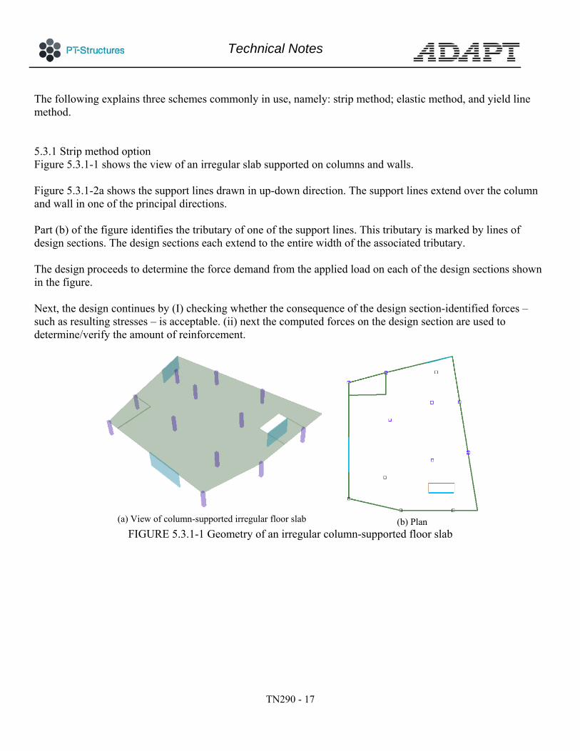
The following explains three schemes commonly in use, namely: strip method; elastic method, and yield line method. 5.3.1 Strip method option Figure 5.3.1-1 shows the view of an irregular slab supported on columns and walls. Figure 5.3.1-2a shows the support lines drawn in up-down direction. The support lines extend over the column and wall in one of the principal directions. Part (b) of the figure identifies the tributary of one of the support lines. This tributary is marked by lines of design sections. The design sections each extend to the entire width of the associated tributary. The design proceeds to determine the force demand from the applied load on each of the design sections shown in the figure. Next, the design continues by (I) checking whether the consequence of the design section-identified forces – such as resulting stresses – is acceptable. (ii) next the computed forces on the design section are used to determine/verify the amount of reinforcement.
(a) View of column-supported irregular floor slab
(b) Plan FIGURE 5.3.1-1 Geometry of an irregular column-supported floor slab

Technical Notes
TN290 - 18
(a) Selection of support lines in up-
down direction
(b) Identification of design sections for
the selected support line FIGURE 5.3.1-2 Plan; irregular floor slab; selection of support lines in up-
down direction, and identification of the associated design strips The selection of the support lines along the line of columns conforms with the construction practice of post-tensioned floor system with unbonded tendons, where the tendons can be positioned along the non-aligned line of columns (Fig. 5.3.1-3).
FIGURE 5.3.2-3 Swerving of tendons along a non-straight
support line.

Technical Notes
TN290 - 19
5.3.2 Elastic solution option In designs based on elastic solution (plate theory), at each location of the slab the reinforcement is determined and placed at the same location. The slab is subdivided into narrow strips in two orthogonal directions (Fig. 5.3.2-1). The width of each strip typically does not exceed three times the slab thickness. In each direction, each of the strips is designed for the force that is acting on it from the elastic solution. In this method, the position of supports does not impact the subdivision of the floor into strips.
(a) Narrow strips in direction 1
(b) Narrow strips in direction 2
FIGURE 5.3.2-1 Breakdown of floor slab into narrow strips in two directions. The strips generally do not exceed three times the slab thickness. The strips are orthogonal to one
another.
5.3-3 Yield line method of design The most effective application of the yield line method is to determine the strength – load carrying capacity – of a floor slab that is either designed, or provided with a known base reinforcement. The analysis determines whether the existing reinforcement can sustain the specified load. Alternatively, what is the load that the floor slab can support before it collapses.

Technical Notes
TN290 - 20
As an example, consider the floor slab shown in Figure 5.3-3.1. The general arrangement of the floor on wall and column supports is shown in part (a) of the Figure. The rooms around the perimeter each have a sanitation enclosure that is provided with a depression in the slab. Part (b) of the figure shows the reinforcement layout from the Subs of the slab. The reinforcement consists of a bottom mesh; top and bottom reinforcement over the wall supports; and top and bottom reinforcement across the central region extending over the range shown by broken line.
(a) See-through view of the typical floor showing the wall supports and the sanitary depressions in the rooms
(b) Display of top and bottom reinforcement in the slab in addition to the bottom mesh over the entire slab. The two broken lines along the central region identify the extent
of the top and bars over this region FIGURE 5.3-3.1 View of floor slab; wall and column supports, and over view of the existing
reinforcement from design Subsequent to construction, it was required to determine the load carrying capacity of the floor. Several collapse mechanisms were envisaged. Some going across the floor slab; others along the perimeter; and one with the focus on the central region of the slab (Fig. 5.3-3.2b). The collapse mechanism envisaged for the central region resulted in the least load capacity. The floor slab was rated for the value of the load obtained from this collapse configuration.
Technical Notes
TN290 - 21
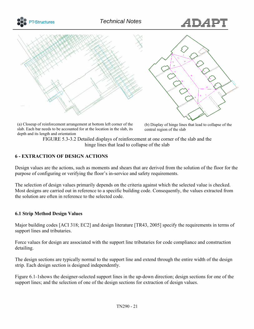
(a) Closeup of reinforcement arrangement at bottom left corner of the slab. Each bar needs to be accounted for at the location in the slab, its depth and its length and orientation
(b) Display of hinge lines that lead to collapse of the central region of the slab
FIGURE 5.3-3.2 Detailed displays of reinforcement at one corner of the slab and the hinge lines that lead to collapse of the slab
6 - EXTRACTION OF DESIGN ACTIONS Design values are the actions, such as moments and shears that are derived from the solution of the floor for the purpose of configuring or verifying the floor’s in-service and safety requirements. The selection of design values primarily depends on the criteria against which the selected value is checked. Most designs are carried out in reference to a specific building code. Consequently, the values extracted from the solution are often in reference to the selected code. 6.1 Strip Method Design Values Major building codes [ACI 318; EC2] and design literature [TR43, 2005] specify the requirements in terms of support lines and tributaries. Force values for design are associated with the support line tributaries for code compliance and construction detailing. The design sections are typically normal to the support line and extend through the entire width of the design strip. Each design section is designed independently. Figure 6.1-1shows the designer-selected support lines in the up-down direction; design sections for one of the support lines; and the selection of one of the design sections for extraction of design values.

Technical Notes
TN290 - 22
FIGURE 6.1-1 Plan of a floor system showing the support lines in the up-down direction; design sections for the displayed support line; and one of the design sections for extraction of design actions.
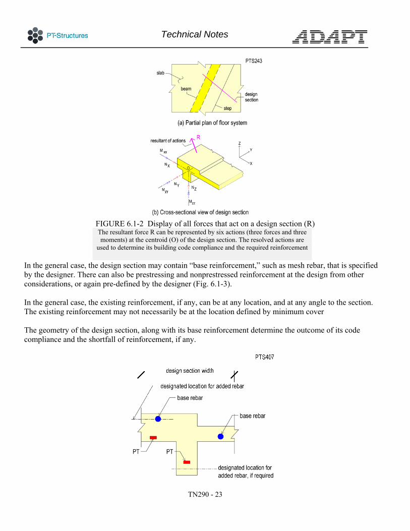
From the elastic solution, the resultant of all forces acting on the face of a design section combine to a single force. The resultant includes moments, shears and axial force. Figure 6.1-2 shows a design section on plan (part a) and the resultant of the actions on the design section – force R (part b). Force R represents the entire forces that act on the design section. The resultant force (R) acting on the design section is transferred to the centroid of the design section (O). At the centroid, the force R is broken down to its six components, namely three moments and three forces. The six components at the centroid include all the stresses and moments on the design section, such as inplane shear, twisting moments and precompression from prestressing and other forces, if any.
Technical Notes
TN290 - 23
FIGURE 6.1-2 Display of all forces that act on a design section (R) The resultant force R can be represented by six actions (three forces and three moments) at the centroid (O) of the design section. The resolved actions are
used to determine its building code compliance and the required reinforcement
In the general case, the design section may contain “base reinforcement,” such as mesh rebar, that is specified by the designer. There can also be prestressing and nonprestressed reinforcement at the design from other considerations, or again pre-defined by the designer (Fig. 6.1-3). In the general case, the existing reinforcement, if any, can be at any location, and at any angle to the section. The existing reinforcement may not necessarily be at the location defined by minimum cover The geometry of the design section, along with its base reinforcement determine the outcome of its code compliance and the shortfall of reinforcement, if any.

Technical Notes
TN290 - 24
FIGURE 6.1-3 Section: partial view of design section showing the available reinforcement (base reinforcement) and the designated location for added reinforcement to meet the serviceability and
safety requirements of design
Each action is applied to the entire cross-sectional geometry of the design strip. For service conditions, such as crack control, a representative stress value is arrived at. Depending on the design code or literature followed, the representative value is referred to as “hypothetical”, “computed”, or “representative” stress. It is a fictious number that represents the state of stress distribution over the cross-section. Its value is derived from the geometry of the section and the resultant force R (Fig. 6.1-2) The computation of the hypothetical stress that represents the entire design strip depends on the code followed. The validity of selecting a single representative stress for the condition of the entire design section is based on distribution of stress across a design strip for common column-supported floors of regular configurations. 6.2 Elastic Solution Option The design based on elastic solution assumes the load path at ultimate limit state to be the same as the elastic response of the slab. This method does not rely on the post-elastic re-distribution of actions in the slab. Figure 6.2-1 illustrates the treatment of a floor slab using the elastic solution. The slab is subdivided into strips in two orthogonal direction. The strips are typically not wider that three times the slab thickness.

Technical Notes
TN290 - 25
FIGURE 6.2-1 Intersection of narrow strips in orthogonal directions forms
the design element The design elements are typically not larger than three times the slab thickness in size. The reinforcement of each design element is based on the actions on the same element
The code-compliance and reinforcement for each design element is evaluated independently. The required reinforcement for each square is placed, within the same square. In practice a base reinforcement, such as mesh is specified over the entire floor plan. The design determines the addition to the base reinforcement, if any. In this design option, the face of each design element is subject to bending and twisting moments; axial force; inplane and normal shear. The design element is checked and reinforced to account for the listed actions within the geometry bounds of the design element. The twisting moment is one of the actions on the design element, for which the adequacy of the design element is checked. This design option does not take advantage of the possible availability of excess reinforcement at one location to provide shortfall of resistance at another location.
7– TREATMENT OF TWISTING MOMENTS When the design follows the strip method, the question of explicit recognition and allowance for twisting moments in design does not arise. Twisting moments are implicit in the design routine. Twisting moments, if

Technical Notes
TN290 - 26
any, become part of the torsion of the design section. In the common case the contribution of twisting moment to the torsion of a design section is not of design significance. This is explained in detail in what follows. On the other hand, when elastic solution is used for ULS design, the reinforcement at each point on the slab needs to cater for the force demand at that point. In this case twisting moments are part of the force demand. Adequate resistance at each design element needs to be recognized. The following explains. 7.1 Twisting Moment Figure 7.1-1 shows the forces that in the general case act on a plate element. The forces are grouped into those that result in change of shape of the element out of its plane – bending (flexural), shown in part (a) of the figure. And, those that result in change of shape of the element within its own plane, such as stretching or change of angle of the element in plan (membrane). In floor slab design, in the absence of post-tensioning, the analysis and design are generally accounts for the bending actions only. Membrane actions are not considered. When post-tensioning is used, the force of post-tensioning, in part, acts in the plane of the slab. In this case both the bending and membrane actions need be considered in analysis and design. One of the bending actions on the element of plate is the twisting moment. The following reviews the impact of the twisting moment and its consideration in design of floor slabs.
(a) Actions on an element of plate causing
deformation of the element out of its plane – bending actions
(b) Actions on an element of plate causing its change of
shape within the plane of the element – membrane actions
FIGURE 7.1-1 Actions on an infinitesimal element of plate. The actions are grouped into those that result in change of shape of the element out of its plane, such as bending, and twisting – (bending actions), and those that result in stretching and change of geometry of the element within its own plane – (membrane actions).
Technical Notes
TN290 - 27
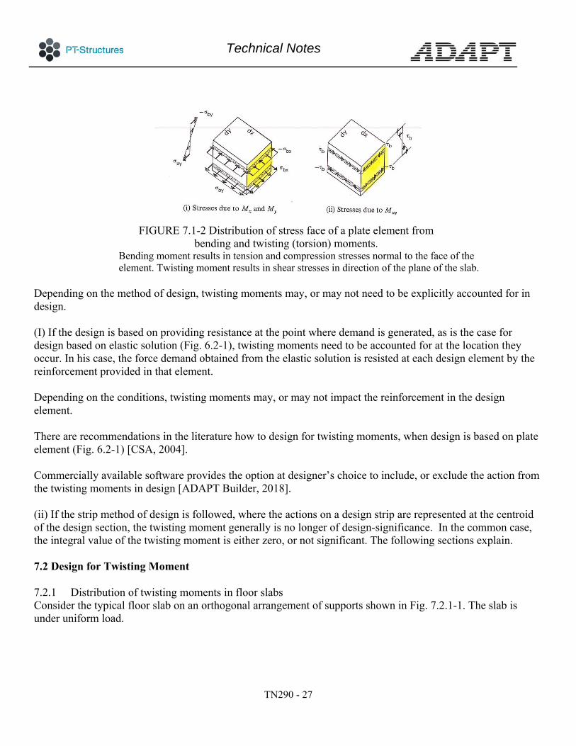
FIGURE 7.1-2 Distribution of stress face of a plate element from
bending and twisting (torsion) moments. Bending moment results in tension and compression stresses normal to the face of the element. Twisting moment results in shear stresses in direction of the plane of the slab.
Depending on the method of design, twisting moments may, or may not need to be explicitly accounted for in design. (I) If the design is based on providing resistance at the point where demand is generated, as is the case for design based on elastic solution (Fig. 6.2-1), twisting moments need to be accounted for at the location they occur. In his case, the force demand obtained from the elastic solution is resisted at each design element by the reinforcement provided in that element. Depending on the conditions, twisting moments may, or may not impact the reinforcement in the design element. There are recommendations in the literature how to design for twisting moments, when design is based on plate element (Fig. 6.2-1) [CSA, 2004]. Commercially available software provides the option at designer’s choice to include, or exclude the action from the twisting moments in design [ADAPT Builder, 2018]. (ii) If the strip method of design is followed, where the actions on a design strip are represented at the centroid of the design section, the twisting moment generally is no longer of design-significance. In the common case, the integral value of the twisting moment is either zero, or not significant. The following sections explain. 7.2 Design for Twisting Moment 7.2.1 Distribution of twisting moments in floor slabs Consider the typical floor slab on an orthogonal arrangement of supports shown in Fig. 7.2.1-1. The slab is under uniform load.
Technical Notes
TN290 - 28
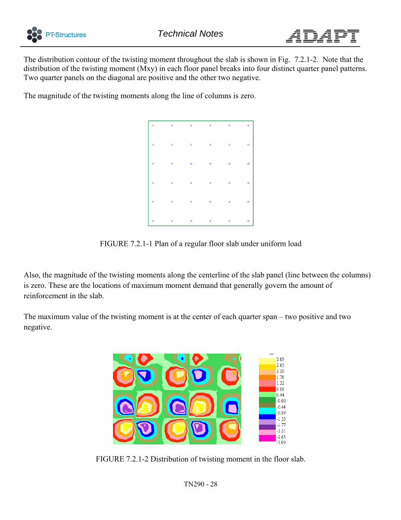
The distribution contour of the twisting moment throughout the slab is shown in Fig. 7.2.1-2. Note that the distribution of the twisting moment (Mxy) in each floor panel breaks into four distinct quarter panel patterns. Two quarter panels on the diagonal are positive and the other two negative. The magnitude of the twisting moments along the line of columns is zero.
FIGURE 7.2.1-1 Plan of a regular floor slab under uniform load Also, the magnitude of the twisting moments along the centerline of the slab panel (line between the columns) is zero. These are the locations of maximum moment demand that generally govern the amount of reinforcement in the slab. The maximum value of the twisting moment is at the center of each quarter span – two positive and two negative.
FIGURE 7.2.1-2 Distribution of twisting moment in the floor slab.

Technical Notes
TN290 - 29
Slab is supported on a regular arrangement of columns The magnitude of the twisting moment along the line of columns is zero. Also, the
magnitude of the twisting moment along the centerline of the panel in each direction is zero.
Additional views of distribution of twisting moment for the regular arrangement of the slab are shown in Fig. 7.2.1-3.
Distribution of twisting moment
(a) The section at the quarter span shows positive and negative equal values of Mxy distribution. The distribution along the column lines and the mid-panel lines is zero

Technical Notes
TN290 - 30
(b) Identification of a typical design strip and design section at quarter span.
The positive and negative values of the twisting moment across the design section cancel one another, leading to zero design value for the twisting moment of the design
section FIGURE7.2.1-3 Distribution of twisting moments in column-supported floor slab The preceding scenario illustrates that when the design is based on strip method, in which the integral of the actions on the design strip are used to determine the required reinforcement, there is no contribution on the demand side from twisting moments – if the general configuration of the slab and loads are regular. The geometry and load on the floor slabs are not always regular. Steps, beams, openings and changes in slab thickness result in non-rectangular design sections. The irregular support layout and load lead to the integral of the twisting moment over a design section not necessarily to be zero. The integral of the actions on the entire surface of the design strip are expressed in terms of three moments and three forces at the centroid of the design section (Fig. ???). These actions are used for code-stipulated stress check; crack control and determination of reinforcement across the design section. Figure 7.2.1.4 shows two of the six actions, namely torsion Myy and Nz. Myy includes the integral of the twisting moment over the entire design section, if any, along with the eccentricity of shear (Nz; part b of the figure) normal to the plane of the slab. Myy = Nz e The objective of expressing the integral of the twisting moment with the eccentricity of vertical shear is to develop an appreciation of the importance, or lack thereof, of twisting moment with eccentricity of shear in non-symmetrical arrangement of a slab. In short, recognition and treatment of torsion (Myy) on the design section includes the consideration of twisting moment on the (Mxy) design section.

Technical Notes
TN290 - 31
FIGURE 7.2.1-4 View of a design section considering two of the six
design actions at the section’s centroid. 7.2.2 Design for twisting moment/torsion Concrete sections have an inherent base resistance to torsion prior to cracking. For slabs, reinforcement to resist torsion is required, once the magnitude of torsion exceeds the threshold that initiates cracks in slab. Cracks from torsion are diagonal to the design section – line of supports. Torsion cracks appear on top and bottom surfaces of the slab. The cracks are shallow; generally, at approximately 45 degrees to the line of columns. It is noteworthy that with over 70 years of extensive experience on design and construction of post-tensioned floors in USA, with thousands of buildings in service, torsion cracks do not appear to have been reported. Performance observation of the existing floor systems leads to the conclusion that design of common residential and commercial floors based on the outlined strip method do not lead to torsion cracks. Recognizing the inherent property of slabs in resisting torsion, ACI 318 specifies a threshold capacity for concrete sections without torsional reinforcement. Torsion reinforcement is required, if the magnitude of torsion exceeds the threshold. In common building construction the magnitude of torsion on a design section is typically below the threshold which would call for torsion reinforcement. This is explained in greater details in the example of this section.

Technical Notes
TN290 - 32
The threshold specified in ACI-3182 is one-quarter of the torsion that would initiate torsional cracks in the member. For prestressed sections, the threshold is:
2'
'0.083 ( ) 1
0.33
cp pcu c
cp c
A fT f
P f
(Exp 7.2.2-1)
Where,
Tu = threshold torsion for reinforcement design [kNm]; = strength reduction factor [0.85];
= factor for concrete weight; for normal weight [1];
f’c = 28-day characteristic compressive strength of concrete cylinder [MPa];
Acp = cross-sectional area of the member [mm2];
Pcp = perimeter of the member [mm]; and
fpc = precompression [MPa].
For common structures, when using strip method with tributaries extending to the entire bay, the value of torsion on design strips is generally below the threshold that would trigger design for reinforcement. The following example provides context for this provision. EXAMPLE Given Floor slab on an array of orthogonally arranged columns with the following parameters; Column spacing 9.144 m (30 ft) Slab thickness 203 mm (8-in.) Columns 406 mm (16-in.) square Concrete 34.47 MPa (5000 psi); normal weight ( = 1)
Precompression (fc) 1.03 MPa (150 psi)
Required
2 ACI 318-11; 11.5.1 (b)

Technical Notes
TN290 - 33
1 - What is the value of the threshold torsion that would require reinforcement in the slab. 2 – How does the torsion threshold compares with the slab’s bending moment at midspan
1 – Torsion threshold Tu Substitution of the values given in the threshold torsion results the following threshold
Tu = 96.65 kNm (69.83 k-ft)
2 – Comparison of torsion threshold Tu with the midspan moment of the panel To provide perspective for the calculated threshold, its value is compared with the bending moment at midspan of the panel from the selfweight of the slab on the same section For an interior span, the moment due to selfweight at midspan of the panel is of the order of
Moment at mid-span is Mu = 152.5 kNm (112.5 k-ft)
The ratio of torsion threshold to mid-span moment is:
/ 96.65 /152.5 63%u uT M
In conclusion, for the current example, the magnitude of torsion at midspan section of the slab should exceed 63% of the selfweight moment at the same location, before it becomes necessary to design for torsion. For the common geometry and design strips selected, this is highly unlikely, knowing that the design torsion due to twisting moment for the symmetrical case is essentially zero for symmetrical conditions. 8 – SUMMARY There are multiple options for safe design concrete floors. Elastic theory, strip method, and yield line theory are three of the major methods. Details of the design, a well as the outcome which is reflected in the amount and arrangement of the reinforcement widely differ among the three methods. For automated design, based on computer software, the elastic theory of plates is the simplest to implement. The shortcoming of the elastic theory is most prominent in post-tensioned slabs. The common practice in the layout of reinforcement and strict adherence with the requirements of building codes are the primary obstacle to the straight application of elastic theory.

Technical Notes
TN290 - 34
Strip method has evolved through the years from the practice of consulting engineers. It conforms with the methods of construction and the requirements of the code. The strip method relies on the engineering judgment of the designer in breaking down the slab into strips that are affine to the floor’s collapse mechanism. The beak down into strips is not always apparent. Commercial software attempts to simplify this. The primary application of the yield line method is to evaluate the strength of slabs with existing or specified reinforcement. REFERENCES Aalami, B. O.,” (2014),Post-Tensioned Buildings; Design and Construction,” www.adaptsoft.com, PT-Structures.com, Rewood City, CA, Mar 2014, 450 pp. ACI-318 (2014), “Building Code Requirements for Structural Concrete and Commentary,” American Concrete Institute, Farmington, MI, www.concrete.org, 519 PP; (2014) ADAPT Builder, (2018), “Software for Design of Concrete Structures,” Redwood City, California, www.adaptsoft.com, 2018 Canadian Standards Association, 2004,”Design of Concrete Structures,” CSA, Ontario, Canada, L4W 5N6, pp.214, 2004 European Code EC2, (2004), “Eurocode 2: Design of Concrete Structures – Part 1-1 General rules and rules for buildings,” Appendix I; European Standard EN 1992-1-1:2004 . Timoshenko, S. P., and Woinowsky-Krieger, S, (1959), “THEORY OF PLATES AND SHELLS,” McGraw-Hill Book Co., New York, pp. 580, 1959 TR43, 2005, “Post-Tensioned Concrete Floors Design Handbook,” The Concrete Society, Camberley, Surrey, UK, concrete.org.uk, 110 pp. 2005 www.ADAPTsoft.com www.PT-Structures.com
This publication is intended for the use of professionals competent to evaluate the significance and limitations of its contents and who will accept responsibility for the application of the materials it contains. The author and the affiliated organizations report the foregoing material as a matter of information and therefore disclaim any and all responsibility for application of the stated principles and procedures or for the accuracy of the sources. The author and the affiliated organizations in publishing these Technical Notes make no warranty regarding the recommendations contained herein, including warranties of quality, workmanship or safety, express or implied, further not limited to, implied warranties or merchantability and fitness for a particular purpose.


![Unleash Stranded Flash Capacity - Disaggregated Storage ...…Test Setup (RocksDB) Fast CRC32 supported: Supported on x86 Options for column family [default]: Options.comparator: leveldb.BytewiseComparator](https://img.pdfslide.us/doc/110x75/5ec6ce8952cf514688065935/unleash-stranded-flash-capacity-disaggregated-storage-test-setup-rocksdb.jpg)